EP0435901B1 - Apparatus and method for safely removing needles from syringes - Google Patents
Apparatus and method for safely removing needles from syringes Download PDFInfo
- Publication number
- EP0435901B1 EP0435901B1 EP89910371A EP89910371A EP0435901B1 EP 0435901 B1 EP0435901 B1 EP 0435901B1 EP 89910371 A EP89910371 A EP 89910371A EP 89910371 A EP89910371 A EP 89910371A EP 0435901 B1 EP0435901 B1 EP 0435901B1
- Authority
- EP
- European Patent Office
- Prior art keywords
- needle
- disconnect
- gear
- housing
- gears
- Prior art date
- Legal status (The legal status is an assumption and is not a legal conclusion. Google has not performed a legal analysis and makes no representation as to the accuracy of the status listed.)
- Expired - Lifetime
Links
- 238000000034 method Methods 0.000 title claims description 16
- 238000003780 insertion Methods 0.000 claims description 3
- 230000037431 insertion Effects 0.000 claims description 3
- 239000004033 plastic Substances 0.000 description 4
- 229920003023 plastic Polymers 0.000 description 4
- 239000008280 blood Substances 0.000 description 3
- 210000004369 blood Anatomy 0.000 description 3
- 230000006835 compression Effects 0.000 description 3
- 238000007906 compression Methods 0.000 description 3
- 125000006850 spacer group Chemical group 0.000 description 3
- 238000010276 construction Methods 0.000 description 2
- 230000001681 protective effect Effects 0.000 description 2
- 208000030507 AIDS Diseases 0.000 description 1
- 239000004809 Teflon Substances 0.000 description 1
- 229920006362 Teflon® Polymers 0.000 description 1
- 210000001124 body fluid Anatomy 0.000 description 1
- 238000000151 deposition Methods 0.000 description 1
- 201000010099 disease Diseases 0.000 description 1
- 208000037265 diseases, disorders, signs and symptoms Diseases 0.000 description 1
- 239000011521 glass Substances 0.000 description 1
- 239000000463 material Substances 0.000 description 1
- 239000002184 metal Substances 0.000 description 1
- 238000012986 modification Methods 0.000 description 1
- 230000004048 modification Effects 0.000 description 1
- 230000035515 penetration Effects 0.000 description 1
- 229910001220 stainless steel Inorganic materials 0.000 description 1
- 239000010935 stainless steel Substances 0.000 description 1
- 210000003462 vein Anatomy 0.000 description 1
Images


Classifications
-
- A—HUMAN NECESSITIES
- A61—MEDICAL OR VETERINARY SCIENCE; HYGIENE
- A61M—DEVICES FOR INTRODUCING MEDIA INTO, OR ONTO, THE BODY; DEVICES FOR TRANSDUCING BODY MEDIA OR FOR TAKING MEDIA FROM THE BODY; DEVICES FOR PRODUCING OR ENDING SLEEP OR STUPOR
- A61M5/00—Devices for bringing media into the body in a subcutaneous, intra-vascular or intramuscular way; Accessories therefor, e.g. filling or cleaning devices, arm-rests
- A61M5/178—Syringes
- A61M5/31—Details
- A61M5/32—Needles; Details of needles pertaining to their connection with syringe or hub; Accessories for bringing the needle into, or holding the needle on, the body; Devices for protection of needles
- A61M5/3205—Apparatus for removing or disposing of used needles or syringes, e.g. containers; Means for protection against accidental injuries from used needles
-
- A—HUMAN NECESSITIES
- A61—MEDICAL OR VETERINARY SCIENCE; HYGIENE
- A61M—DEVICES FOR INTRODUCING MEDIA INTO, OR ONTO, THE BODY; DEVICES FOR TRANSDUCING BODY MEDIA OR FOR TAKING MEDIA FROM THE BODY; DEVICES FOR PRODUCING OR ENDING SLEEP OR STUPOR
- A61M5/00—Devices for bringing media into the body in a subcutaneous, intra-vascular or intramuscular way; Accessories therefor, e.g. filling or cleaning devices, arm-rests
- A61M5/178—Syringes
- A61M5/31—Details
- A61M5/32—Needles; Details of needles pertaining to their connection with syringe or hub; Accessories for bringing the needle into, or holding the needle on, the body; Devices for protection of needles
- A61M5/3205—Apparatus for removing or disposing of used needles or syringes, e.g. containers; Means for protection against accidental injuries from used needles
- A61M2005/3208—Apparatus for removing or disposing of used needles or syringes, e.g. containers; Means for protection against accidental injuries from used needles by application of rotational movement to the needle hub, e.g. by use of electrically driven toothed wheels
Definitions
- the present invention relates to the disposal of blood contaminated needles attached using rotating connectors such as screw connectors or luer locks to syringes, and more particularly relates to a apparatus and method for removing such needles and depositing them into a container in a one-handed operation which greatly reduces the exposure of the user to being injured by the contaminated needle.
- a syringe of the type sold under the trademark VACUUTAINER is used by securing a double needle to a needle retainer by screwing a threaded collar on the needle into a threaded opening in the end of the needle retainer.
- VACUUTAINER is used by securing a double needle to a needle retainer by screwing a threaded collar on the needle into a threaded opening in the end of the needle retainer.
- a partially evacuated sample tube is forced onto the other needle point inside the retainer, and blood is sucked into the sample tube.
- the sample tube is removed and sent for analysis of its contents, and the needle retainer may be reused. Therefore, medical personnel typically remove the needle by unscrewing it,and place the needle in an approved disposal container.
- syringes also use disposable needles with non-disposal suction devices.
- the needles may be connected by threaded screw connectors, luer locks, or the like.
- Disposable needles are typically fitted with plastic collars which have flange-like projections suitable for grasping with the fingers when twisting the needle into or out of the needle retaining portion of a syringe.
- the user holds the needle retainer, inserts the needle into the slot until the flanges of the collar are even with the slot, moves the needle into the smaller end of the slot until the flanges engage the slot, and twists the needle retainer to unscrew or unlock the needle, which falls into the container.
- This procedure has significant disadvantages.
- the user must position the needle carefully and supply the force necessary to rotate the needle retainer.
- the user must use two hands for the operation, one to steady the container, and one to manipulate the syringe and needle. This often results in the user laying down the used syringe for a time until both hands are available for removing the needle, rather than immediately placing the needle into a safe container.
- EP-A-313212 is a prior art document for the purpose of Art. 54(3) EPC and discloses a device for removing needles or needle/sheath combinations from hypodermic syringes.
- the device includes a gripping mechanism for releasably gripping the needle/combination and a drive mechanism for causing rotation of the gripped needle/combination thereby to release the needle/combination for disposal.
- the present invention solves significant problems in the art by providing a needle removal apparatus and method according to which the user, touching only the needle retaining portion of the syringe, inserts the needle into a device which automatically rotates the needle to disconnect it from the syringe.
- the present invention provides an apparatus for removing needles of the type received in syringe bodies by way of a rotating connector, and defining a collar positioned outside the syringe body, comprising a needle guide housing defining an insert opening for receiving the needle; and means for engaging the collar and rotating the needle, such that the needle is released from the syringe.
- the means for rotating the needle comprises at least one disconnect wheel rotatably mounted adjacent to the insert opening, the wheel defining means at is periphery, facing the insert opening, for engaging the needle collar; and means for rotating the disconnect wheel in a disconnect direction responsive to downward movement of the needle into the insert opening.
- the means for rotating the needle preferably comprises at least one disconnect gear rotatably mounted adjacent to the insert opening with teeth facing the insert opening, so that the needle flanges engage the gear teeth.
- the needle guide housing may be mounted for movement within an actuator housing: and the means for rotating the gear may comprise a drive gear engaging the disconnect gear, with the drive gear defining a cam follower.
- a cam track is then positioned in the actuator housing to receive the cam follower and shaped so as to move the drive gear with respect to the disconnect gear as the needle guide housing moves within the actuator housing responsive to pressure exerted on the needle.
- a needle removal apparatus preferably includes a container adjacent to the needle rotating means for confining needles removed from syringes.
- the present invention also provides a method of removing a needle from a syringe body to which the needle is attached by a rotating connector, generally comprising the steps of inserting the needle into an opening in a housing and engaging the syringe body against the housing; exerting pressure against the housing; and responsive to the pressure, rotating the needle sufficiently to release the needle from the syringe body.
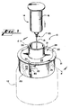
- Fig. 1 is a pictorial view of a needle removal apparatus embodying the present invention.
- Fig. 2 is a top plan view of the apparatus shown in Fig. 1.
- Fig. 3 is an exploded view of the elements of the apparatus shown in Fig. 1.
- Fig. 4 is a vertical cross sectional view taken along line 4--4 of Fig. 1.
- Fig. 5 is a top view of the apparatus of Fig. 1, with the needle guide housing and actuator housing removed, and with parts broken away to show interior detail.
- Fig. 6 is a side plan view of the circular drive gear.
- Fig. 7 is a pictorial view of one of the disconnect gears.
- Fig. 8 is a pictorial view of the disconnect gear of Fig.. 7, taken from the opposite side.
- Fig. 9 is a top plan view of the gear shown in Fig. 7.
- Fig. 10 is a side plan view of the gear shown in Fig. 9, showing the ramp profile.
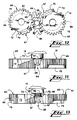
- Fig. 11 is a diagrammatic side view of the disconnect gears and a needle initially inserted into engagement with the gears.
- Fig. 12 is a diagrammatic top view of the situation shown in Fig. 11.
- Fig. 13 is a diagrammatic side view of the same needle pushed further into the apparatus between the disconnect gears.
- Fig. 14 is a diagrammatic side view of the same needle pushed far enough into the apparatus to disconnect the needle from the needle retainer.
- Fig. 15 is a diagrammatic top view of the situation shown in Fig. 14.
- Fig. 16 is a side view of a syringe assembly with portions broken away.
- Fig. 17 is a bottom view of the syringe assembly of Fig. 16.
- Fig. 1 shows a needle removal apparatus 10 embodying the invention.
- the needle removal apparatus 10 is normally mounted in the mouth of a container 12, shown in dotted lines in Fig. 1.
- the container 12 may be a glass or plastic jar, for example.
- a syringe assembly 14 is shown in a position prior to insertion in the needle removal apparatus 10, and includes a needle 15 and a needle retainer portion 16. When the assembly 14 is inserted in the direction of the arrow, the parts of the needle removal apparatus described below automatically disconnect the needle 15 from the retainer 16.
- the apparatus 10 includes an actuator housing 20, which is a cylinder open at both ends. Its top end is surrounded by an annular flange 21 which extends radially outwardly from the cylindrical wall.
- the housing 20 defines three vertical slots 22 which intersect the flange 21 and extend down to a point spaced above the bottom of the housing 20.
- the interior of the cylindrical wall defines three arcuate grooves 25 extending at an angle, preferably 40-60 degrees from the horizontal, from just under the flange 21 to the bottom of the housing 20. These grooves 25 form cam tracks or female screw threads to cause rotary motion, as described below.
- a needle guide housing 28 which is formed having a horizontal annular plate 29. As shown in Fig. 2, three tabs 30 extend outwardly from the circumference of the annular plate 29 and enter the slots 22 of the actuator housing 20. The tabs 30 thus prevent the housing 28 from rotating, but allow vertical movement.
- a cylindrical throat 31 rises from the center of the plate 29 and provides an initial guide way for a syringe assembly inserted into the apparatus 10. At the bottom of the throat 31, slightly below the plane of the plate 29, an annular shoulder 32 is formed around an insert opening 33, into which the needle 15 is placed.
- a pair of gear shafts 34 and 35 extend vertically downward on opposite sides of the insert opening 33.
- the shafts terminate in lock posts 37 and 38, which are somewhat smaller in diameter than the shafts 34 and 35.
- the needle guide housing 28 also defines three spring stop tabs 40 which project downwardly near the periphery of the annular plate 29. The tabs 40 are spaced evenly around the plate 29.
- a drive gear 45 having a circular cross section fits around the gear shafts 34 and 35 and has a diameter slightly smaller than the inside diameter of the actuator housing 20, as shown in Fig. 4.
- the drive gear 45 defines an inner circular gear 47 adjacent the bottom surface 46 of the drive gear 45.
- a central bore 48 of diameter less than that of the circular teeth 47 is formed axially through the gear 45.
- three arcuate spring tracks 50 are cut into the top surface 49 of the drive gear 45. These tracks 50 have a semicircular bottom profile which matingly receives the ends of the spring stop tabs 40 extending downwardly from the needle guide housing 28.
- Narrow walls 51 formed between the spring tracks 50 act as spring compression actuators in the manner described below.
- Coil springs 57 are placed within the tracks 50 between one of the walls 51 and one of the stop tabs 40, as shown in Fig. 5.
- Three balls 58 of plastic, Teflon, stainless steel, or other material are also placed in each track 50 on the other side of each tab 40 from the spring 57. The purpose of the balls is to provide spacing and reduce friction between the drive gear 45 and the needle guide housing 28.
- rounded nibs or projections extending from either element could provide these functions.
- a pair of needle disconnect or unscrewing gears 60 and 61 are rotatably journalled on the gear shafts 34 and 35.
- the structure of these gears is best shown in Figs. 7-10.
- the shafts 34 and 35 are received through central bores 63.
- An outer series of teeth 65 mesh with the teeth 47 of the drive gear 45, as shown in Fig. 5, and provide about 115 degrees of rotation of the disconnect gears 60 and 61 about the shafts 34 and 35.
- the teeth 67 are formed differently from the teeth 65 for the specific purpose of engaging and unscrewing the needle, as explained below.
- the series 67 begins with a alignment tooth 68.
- a ramp 70 is cut out of the gears 60 and 61 through the arc of the teeth 67, beginning at about the center of the alignment tooth 68 and sloping downwardly to meet a dropout opening 72, positioned in the embodiment shown about 115 degrees from the alignment tooth.
- the ramp accommodates portions of the needle assembly as it is unscrewed, and the dropout opening 72 allows the needle to drop vertically when it is fully unscrewed from the retainer 16.
- the arcuate travel of the gears 60 and 61 is limited by rotation limiting cutouts 75 made in the lower portion of the outer series teeth 65.
- the ends of the cutouts 75 meet stops to be described below, and thereby stop motion of the gears when the dropout openings 72 are aligned with one another.
- the arcuate length of the teeth 67 determines how many turns of the needle are made before the dropout opening is reached, and this arcuate length may be varied in accordance with the number of turns needed to release the needle from the particular locking device being used. For example, a luer lock may require only a portion of a turn, whereas a conventional screw connector may require about 1.5 to 2 turns. Also affected by the required number of turns is the length of the outer series of teeth 65, which may be constructed to provide more or less than the 115 degrees of rotation described above.
- a pair of coil springs 78 are placed onto the shafts 34 and 35 under the gears 60 and 61.
- the springs 78 are for the purpose of allowing the gears to yield downwardly if the needle 15 is not fully seated in the needle retainer 16.
- the final element of the needle removal apparatus 10 is a circular bottom plate 80, which includes an upwardly extending cylindrical wall 82 at the periphery of the plate 80.
- the bottom plate 80 defines a pair of openings 84 which receive the lock posts 37 and 38 at the ends of the shafts 34 and 35.
- a pair of flexible lock rings of conventional construction are forced onto the projecting lock posts to hold the bottom plate 80, and therefore the drive gear 45 and disconnect gears 60 and 61, in place beneath the needle guide housing 28.
- a pair of V-shaped spacers extend upwardly from the bottom plate to meet and support the housing 28 at the insert opening 33. These spacers also help to keep the needle in a relatively straight axial orientation as it is being inserted between the gears 60 and 61.
- a central opening 85 is formed in the bottom plate 80 below the insert opening 33, to allow disconnected needles to drop out of the apparatus.
- a pair of stops 86 extend upwardly from the bottom plate into the rotation limiting cutouts 75 of the gears 60 and 61.
- the stops 86 are positioned so that they are engaged by the gears when the dropout openings 72 in the gears are aligned.
- the cylindrical wall 82 is dimensioned to extend up to engage the bottom the drive gear 45, and positions the drive gear under the housing 28 without forcing the parts together so as to cause excess friction during rotation of the drive gear 45.
- the springs 78 urge the disconnect gears toward bearing surfaces on the bottom of the housing 28.
- FIG. 6 is a view downwardly into the apparatus with the needle guide housing 28 removed.
- a vertical space for receiving the needle is bounded by the two disconnect gears 60 and 61, and the two spacers 83.
- the needle removal apparatus is intended to be disposable after a period of use, such as when the container 12 is full.
- all of the elements described above are preferably made of suitable plastics known to those skilled in the art, although metal can be utilized where appropriate.
- the needle 15 extends into a collar 95, which defines a plurality of outwardly extending flanges 96.
- the flanges terminate in a circular stop 97, which separates them from a threaded screw portion 98.
- the collar 95 is screwed into a tapped hole in the retainer portion 16 of the syringe 14, with an inner needle 99 (shown covered by a protective envelope) extending into the retainer 16.
- the flanges 96 are provided to allow the user to get a grip on the needle for screwing and unscrewing the needle. It is the object of the present invention to obviate the need for grasping the collar by hand to unscrew it after the needle is contaminated.
- the retainer portion 16 includes a leading surface 100, which engages the annular shoulder 32 within the needle guide housing 28.
- Figs. 11-15 show a sequence of positions of the disconnect gears 60 and 61 during operation.
- the user simply takes the needle retainer 16 in one hand and inserts it into the throat 31 of the needle guide housing 28, until the needle 15 passes into the space between the disconnect gears, and the leading surface 100 of the retainer 16 is in contact with the annular shoulder 32.
- the flanges 96 have engaged the alignment teeth 68 of both gears 60 and 61, and have been caused to align the syringe so that the flanges are astride the alignment teeth as shown in Figs. 11 and 12.
- the position of the syringe at this point in the operation is shown in dotted lines in Fig. 4.
- Detachment of the needle 15 from the retainer 16 is accomplished when the user asserts downward pressure on the retainer. This pressure causes the needle guide housing 28 to begin to move downwardly along the slots 22 in the actuator housing 20. As this occurs, the cam followers 55 of the drive gear 45 are forced to follow the path defined by the cam tracks 25 of the actuator housing 20. Thus, the drive gear 45 rotates counterclockwise as it descends with the needle guide housing 28, and its rotation causes the following other functions to be carried out.
- the rotating inner teeth 47 cause rotation of the disconnect gears 60 and 61, in turn causing the inner unscrewing teeth 67 to move relative to the flanges 96 of the needle collar 95.
- the teeth 67 engage the flanges 96 and turn the collar in an unscrewing direction (clockwise looking down as in Figs. 12 and 15) as the gears turn. After a portion of the permitted rotation, the needle collar position is shown in Fig. 13. The threaded portion 98 has begun to emerge from the needle retainer 16. The ramp 70 provides room for the circular stop 97 to move downwardly past the gears, while the flanges remain engaged with the inner unscrewing teeth 67.
- the drive gear 45 rotates, it causes the spring compression walls 51 to compress the return springs 57 against the spring stops 40, which do not rotate.
- the springs are compressed through about 53 degrees of arc.
- the balls 58 roll between the needle guide housing 28 and the spring tracks 50, in the space created by the departure of the adjacent wall 51 from its rest position.
- the user may terminate downward pressure on the needle retainer 16 and withdraw it from the throat 31.
- the energy stored in the compressed return springs 57 now causes the drive gear 45 to rotate in the opposite direction.
- the cam followers 55 climb back up the cam tracks 25, and the needle guide housing moves up the slots 22.
- the apparatus stops rotating, and reaches its original orientation as the balls 58 become trapped between the stops 40 and the walls 51.
- the alignment teeth 68 of the gears 60 and 61 are now reset across from one another ready to receive the next needle collar.
- the circular stop 97 may engage the top of the gears 60 and 61 before the leading surface 100 meets the annular shoulder 32 of the needle guide housing.
- the springs 78 will allow the gears to yield downwardly, so that the flanges will still engage the teeth 68 and the retainer will transmit pressure to the needle guide housing.
- the return function provided by the return springs 57 could be performed by compression springs mounted below the bottom plate 80 to urge the assembled parts upwardly when pressure is released.
- the needle collar could be engaged for unscrewing by means other than gear teeth.
- the disconnect gears could be wheels having resilient outer bands for frictionally engaging the needle and/or the interior of the drive gear, which could also be lined with a high friction interface rather than gear teeth.
- the needle collar could be rotated by a rack or racks caused to move past the collar.
Landscapes
- Health & Medical Sciences (AREA)
- Engineering & Computer Science (AREA)
- Life Sciences & Earth Sciences (AREA)
- Animal Behavior & Ethology (AREA)
- Anesthesiology (AREA)
- Biomedical Technology (AREA)
- Heart & Thoracic Surgery (AREA)
- Hematology (AREA)
- Environmental & Geological Engineering (AREA)
- Vascular Medicine (AREA)
- General Health & Medical Sciences (AREA)
- Public Health (AREA)
- Veterinary Medicine (AREA)
- Accommodation For Nursing Or Treatment Tables (AREA)
- Infusion, Injection, And Reservoir Apparatuses (AREA)
- Control And Other Processes For Unpacking Of Materials (AREA)
- Electrical Discharge Machining, Electrochemical Machining, And Combined Machining (AREA)
Abstract
Description
- The present invention relates to the disposal of blood contaminated needles attached using rotating connectors such as screw connectors or luer locks to syringes, and more particularly relates to a apparatus and method for removing such needles and depositing them into a container in a one-handed operation which greatly reduces the exposure of the user to being injured by the contaminated needle.
- Each day, staggering quantities of disposable needles are used in hospitals, clinics, and physicians' offices. Many such needles are attached to syringes which are not discarded with the needles. For example, a syringe of the type sold under the trademark VACUUTAINER is used by securing a double needle to a needle retainer by screwing a threaded collar on the needle into a threaded opening in the end of the needle retainer. After the needle point outside the needle retainer is inserted into the patient's vein, a partially evacuated sample tube is forced onto the other needle point inside the retainer, and blood is sucked into the sample tube. The sample tube is removed and sent for analysis of its contents, and the needle retainer may be reused. Therefore, medical personnel typically remove the needle by unscrewing it,and place the needle in an approved disposal container.
- Other types of syringes also use disposable needles with non-disposal suction devices. The needles may be connected by threaded screw connectors, luer locks, or the like. Disposable needles are typically fitted with plastic collars which have flange-like projections suitable for grasping with the fingers when twisting the needle into or out of the needle retaining portion of a syringe.
- Personnel at hospitals and other medical facilities face a growing problem of safe disposal of needles because of the rise of diseases carried by the blood and other bodily fluids, such as AIDS. Manipulation of needle connectors after use can present a grave risk of being pricked by the exposed, contaminated needle. Attempts to insert the needle back into the protective sleeve provided for shipment create a similar risk. Past efforts to assist personnel in removing needles have reduced the danger somewhat, but have resulted in devices that are inconvenient to use. One such device is simply a container having a tapering slot in the top. The user holds the needle retainer, inserts the needle into the slot until the flanges of the collar are even with the slot, moves the needle into the smaller end of the slot until the flanges engage the slot, and twists the needle retainer to unscrew or unlock the needle, which falls into the container. This procedure has significant disadvantages. The user must position the needle carefully and supply the force necessary to rotate the needle retainer. Usually, the user must use two hands for the operation, one to steady the container, and one to manipulate the syringe and needle. This often results in the user laying down the used syringe for a time until both hands are available for removing the needle, rather than immediately placing the needle into a safe container. These disadvantages increase the opportunity and risk that a person will come into contact with the contaminated needle.
- Thus, a need exists in the art for a needle removal system which can remove the disposable needle from the syringe with minimal non-precise manipulation of the needle and syringe using only one hand.
- EP-A-313212 is a prior art document for the purpose of Art. 54(3) EPC and discloses a device for removing needles or needle/sheath combinations from hypodermic syringes. The device includes a gripping mechanism for releasably gripping the needle/combination and a drive mechanism for causing rotation of the gripped needle/combination thereby to release the needle/combination for disposal.
- The present invention solves significant problems in the art by providing a needle removal apparatus and method according to which the user, touching only the needle retaining portion of the syringe, inserts the needle into a device which automatically rotates the needle to disconnect it from the syringe.
- Generally described, the present invention provides an apparatus for removing needles of the type received in syringe bodies by way of a rotating connector, and defining a collar positioned outside the syringe body, comprising a needle guide housing defining an insert opening for receiving the needle; and means for engaging the collar and rotating the needle, such that the needle is released from the syringe. In the preferred embodiment of the invention, the means for rotating the needle comprises at least one disconnect wheel rotatably mounted adjacent to the insert opening, the wheel defining means at is periphery, facing the insert opening, for engaging the needle collar; and means for rotating the disconnect wheel in a disconnect direction responsive to downward movement of the needle into the insert opening.
- Many disposable needles include a plurality of flanges extending outwardly from the collar, and in this case the means for rotating the needle preferably comprises at least one disconnect gear rotatably mounted adjacent to the insert opening with teeth facing the insert opening, so that the needle flanges engage the gear teeth. The needle guide housing may be mounted for movement within an actuator housing: and the means for rotating the gear may comprise a drive gear engaging the disconnect gear, with the drive gear defining a cam follower. A cam track is then positioned in the actuator housing to receive the cam follower and shaped so as to move the drive gear with respect to the disconnect gear as the needle guide housing moves within the actuator housing responsive to pressure exerted on the needle.
- A needle removal apparatus according to the invention preferably includes a container adjacent to the needle rotating means for confining needles removed from syringes.
- The present invention also provides a method of removing a needle from a syringe body to which the needle is attached by a rotating connector, generally comprising the steps of inserting the needle into an opening in a housing and engaging the syringe body against the housing; exerting pressure against the housing; and responsive to the pressure, rotating the needle sufficiently to release the needle from the syringe body.
- Thus, it is an object of the present invention to provide an improved apparatus and method of removing needles from syringes and the like.
- It is a further object of the present invention to provide a needle removal system which can be operated using one hand.
- It is a further object of the present invention to provide a needle removal system which does not require precise manipulation of the needle to achieve removal.
- It is a further object of the present invention to provide a needle removal system which presents little danger to the user.
- It is a further object of the present invention to provide a needle removal system which can be used quickly and conveniently.
- Other objects, features, and advantages of the present invention will become apparent upon reading the following detailed description of embodiments of the invention,when taken in conjunction with the accompanying drawing and the appended claims.
- Fig. 1 is a pictorial view of a needle removal apparatus embodying the present invention.
- Fig. 2 is a top plan view of the apparatus shown in Fig. 1.
- Fig. 3 is an exploded view of the elements of the apparatus shown in Fig. 1.
- Fig. 4 is a vertical cross sectional view taken along
line 4--4 of Fig. 1. - Fig. 5 is a top view of the apparatus of Fig. 1, with the needle guide housing and actuator housing removed, and with parts broken away to show interior detail.
- Fig. 6 is a side plan view of the circular drive gear.
- Fig. 7 is a pictorial view of one of the disconnect gears.
- Fig. 8 is a pictorial view of the disconnect gear of Fig.. 7, taken from the opposite side.
- Fig. 9 is a top plan view of the gear shown in Fig. 7.
- Fig. 10 is a side plan view of the gear shown in Fig. 9, showing the ramp profile.
- Fig. 11 is a diagrammatic side view of the disconnect gears and a needle initially inserted into engagement with the gears.
- Fig. 12 is a diagrammatic top view of the situation shown in Fig. 11.
- Fig. 13 is a diagrammatic side view of the same needle pushed further into the apparatus between the disconnect gears.
- Fig. 14 is a diagrammatic side view of the same needle pushed far enough into the apparatus to disconnect the needle from the needle retainer.
- Fig. 15 is a diagrammatic top view of the situation shown in Fig. 14.
- Fig. 16 is a side view of a syringe assembly with portions broken away.
- Fig. 17 is a bottom view of the syringe assembly of Fig. 16.
- Referring now to the drawing, in which like numerals refer to like parts throughout the several views, Fig. 1 shows a
needle removal apparatus 10 embodying the invention. Theneedle removal apparatus 10 is normally mounted in the mouth of acontainer 12, shown in dotted lines in Fig. 1. Thecontainer 12 may be a glass or plastic jar, for example. Asyringe assembly 14 is shown in a position prior to insertion in theneedle removal apparatus 10, and includes aneedle 15 and aneedle retainer portion 16. When theassembly 14 is inserted in the direction of the arrow, the parts of the needle removal apparatus described below automatically disconnect theneedle 15 from theretainer 16. - Referring to Figs. 1 and 2, the
apparatus 10 includes anactuator housing 20, which is a cylinder open at both ends. Its top end is surrounded by anannular flange 21 which extends radially outwardly from the cylindrical wall. Thehousing 20 defines threevertical slots 22 which intersect theflange 21 and extend down to a point spaced above the bottom of thehousing 20. The interior of the cylindrical wall defines threearcuate grooves 25 extending at an angle, preferably 40-60 degrees from the horizontal, from just under theflange 21 to the bottom of thehousing 20. Thesegrooves 25 form cam tracks or female screw threads to cause rotary motion, as described below. - Fitted for vertical motion within the
actuator housing 20 is aneedle guide housing 28, which is formed having a horizontalannular plate 29. As shown in Fig. 2, threetabs 30 extend outwardly from the circumference of theannular plate 29 and enter theslots 22 of theactuator housing 20. Thetabs 30 thus prevent thehousing 28 from rotating, but allow vertical movement. Acylindrical throat 31 rises from the center of theplate 29 and provides an initial guide way for a syringe assembly inserted into theapparatus 10. At the bottom of thethroat 31, slightly below the plane of theplate 29, anannular shoulder 32 is formed around aninsert opening 33, into which theneedle 15 is placed. A pair ofgear shafts insert opening 33. The shafts terminate in lock posts 37 and 38, which are somewhat smaller in diameter than theshafts housing 28 also defines threespring stop tabs 40 which project downwardly near the periphery of theannular plate 29. Thetabs 40 are spaced evenly around theplate 29. - Several other elements shown in Fig. 3 are connected to the
needle guide housing 28 and move with it within theactuator housing 20. Adrive gear 45 having a circular cross section fits around thegear shafts actuator housing 20, as shown in Fig. 4. Thedrive gear 45 defines an innercircular gear 47 adjacent thebottom surface 46 of thedrive gear 45. Acentral bore 48 of diameter less than that of thecircular teeth 47 is formed axially through thegear 45. In the annular space remaining, three arcuate spring tracks 50 are cut into thetop surface 49 of thedrive gear 45. Thesetracks 50 have a semicircular bottom profile which matingly receives the ends of thespring stop tabs 40 extending downwardly from theneedle guide housing 28.Narrow walls 51 formed between the spring tracks 50 act as spring compression actuators in the manner described below. Coil springs 57 are placed within thetracks 50 between one of thewalls 51 and one of thestop tabs 40, as shown in Fig. 5. Threeballs 58 of plastic, Teflon, stainless steel, or other material are also placed in eachtrack 50 on the other side of eachtab 40 from thespring 57. The purpose of the balls is to provide spacing and reduce friction between thedrive gear 45 and theneedle guide housing 28. Those skilled in the art will understand that rounded nibs or projections extending from either element could provide these functions. - After the drive gear and springs are fitted under the
needle guide housing 28, a pair of needle disconnect or unscrewing gears 60 and 61 are rotatably journalled on thegear shafts shafts central bores 63. An outer series ofteeth 65 mesh with theteeth 47 of thedrive gear 45, as shown in Fig. 5, and provide about 115 degrees of rotation of the disconnect gears 60 and 61 about theshafts teeth 67, one on each of thegears insert opening 33. Theteeth 67 are formed differently from theteeth 65 for the specific purpose of engaging and unscrewing the needle, as explained below. Theseries 67 begins with aalignment tooth 68. Aramp 70 is cut out of thegears teeth 67, beginning at about the center of thealignment tooth 68 and sloping downwardly to meet adropout opening 72, positioned in the embodiment shown about 115 degrees from the alignment tooth. As explained in more detail below, the ramp accommodates portions of the needle assembly as it is unscrewed, and thedropout opening 72 allows the needle to drop vertically when it is fully unscrewed from theretainer 16. - The arcuate travel of the
gears rotation limiting cutouts 75 made in the lower portion of theouter series teeth 65. The ends of thecutouts 75 meet stops to be described below, and thereby stop motion of the gears when thedropout openings 72 are aligned with one another. The arcuate length of theteeth 67 determines how many turns of the needle are made before the dropout opening is reached, and this arcuate length may be varied in accordance with the number of turns needed to release the needle from the particular locking device being used. For example, a luer lock may require only a portion of a turn, whereas a conventional screw connector may require about 1.5 to 2 turns. Also affected by the required number of turns is the length of the outer series ofteeth 65, which may be constructed to provide more or less than the 115 degrees of rotation described above. - A pair of
coil springs 78 are placed onto theshafts gears springs 78 are for the purpose of allowing the gears to yield downwardly if theneedle 15 is not fully seated in theneedle retainer 16. - The final element of the
needle removal apparatus 10 is acircular bottom plate 80, which includes an upwardly extendingcylindrical wall 82 at the periphery of the plate 80.Thebottom plate 80 defines a pair ofopenings 84 which receive the lock posts 37 and 38 at the ends of theshafts bottom plate 80, and therefore thedrive gear 45 and disconnect gears 60 and 61, in place beneath theneedle guide housing 28. In this configuration, shown in Fig. 4, a pair of V-shaped spacers extend upwardly from the bottom plate to meet and support thehousing 28 at theinsert opening 33. These spacers also help to keep the needle in a relatively straight axial orientation as it is being inserted between thegears central opening 85 is formed in thebottom plate 80 below theinsert opening 33, to allow disconnected needles to drop out of the apparatus. - A pair of
stops 86 extend upwardly from the bottom plate into therotation limiting cutouts 75 of thegears dropout openings 72 in the gears are aligned. Thecylindrical wall 82 is dimensioned to extend up to engage the bottom thedrive gear 45, and positions the drive gear under thehousing 28 without forcing the parts together so as to cause excess friction during rotation of thedrive gear 45. Thesprings 78 urge the disconnect gears toward bearing surfaces on the bottom of thehousing 28. - Further details of the assembled configuration may be perceived from Fig. 6, which is a view downwardly into the apparatus with the
needle guide housing 28 removed. A vertical space for receiving the needle is bounded by the two disconnect gears 60 and 61, and the twospacers 83. - The needle removal apparatus is intended to be disposable after a period of use, such as when the
container 12 is full. Thus, all of the elements described above are preferably made of suitable plastics known to those skilled in the art, although metal can be utilized where appropriate. - Further details of the construction of a typical
conventional syringe assembly 14 are shown in Figs. 16 and 17. Theneedle 15 extends into acollar 95, which defines a plurality of outwardly extendingflanges 96. The flanges terminate in acircular stop 97, which separates them from a threadedscrew portion 98. Thecollar 95 is screwed into a tapped hole in theretainer portion 16 of thesyringe 14, with an inner needle 99 (shown covered by a protective envelope) extending into theretainer 16. Theflanges 96 are provided to allow the user to get a grip on the needle for screwing and unscrewing the needle. It is the object of the present invention to obviate the need for grasping the collar by hand to unscrew it after the needle is contaminated. Theretainer portion 16 includes a leadingsurface 100, which engages theannular shoulder 32 within theneedle guide housing 28. - Operation of the needle removal apparatus is described as follows, with particular reference to Figs. 11-15,which show a sequence of positions of the disconnect gears 60 and 61 during operation. After the
syringe assembly 14 has been used and theneedle 15 contaminated, the user simply takes theneedle retainer 16 in one hand and inserts it into thethroat 31 of theneedle guide housing 28, until theneedle 15 passes into the space between the disconnect gears, and the leadingsurface 100 of theretainer 16 is in contact with theannular shoulder 32. At this point, theflanges 96 have engaged thealignment teeth 68 of bothgears - Detachment of the
needle 15 from theretainer 16 is accomplished when the user asserts downward pressure on the retainer. This pressure causes theneedle guide housing 28 to begin to move downwardly along theslots 22 in theactuator housing 20. As this occurs, thecam followers 55 of thedrive gear 45 are forced to follow the path defined by the cam tracks 25 of theactuator housing 20. Thus, thedrive gear 45 rotates counterclockwise as it descends with theneedle guide housing 28, and its rotation causes the following other functions to be carried out. The rotatinginner teeth 47 cause rotation of the disconnect gears 60 and 61, in turn causing theinner unscrewing teeth 67 to move relative to theflanges 96 of theneedle collar 95. Theteeth 67 engage theflanges 96 and turn the collar in an unscrewing direction (clockwise looking down as in Figs. 12 and 15) as the gears turn. After a portion of the permitted rotation, the needle collar position is shown in Fig. 13. The threadedportion 98 has begun to emerge from theneedle retainer 16. Theramp 70 provides room for thecircular stop 97 to move downwardly past the gears, while the flanges remain engaged with theinner unscrewing teeth 67. - As the
drive gear 45 rotates, it causes thespring compression walls 51 to compress the return springs 57 against the spring stops 40, which do not rotate. In the embodiment shown in Fig. 5, the springs are compressed through about 53 degrees of arc. At the same time, theballs 58 roll between theneedle guide housing 28 and the spring tracks 50, in the space created by the departure of theadjacent wall 51 from its rest position. - When the rotation of the disconnect gears 60 and 61 has reached the configuration shown in Figs. 14 and 15, the threaded
portion 98 of thecollar 95 has been completely unthreaded from theretainer 16, and the collar has moved down theramp 70 into thedropout openings 72, which are now aligned across from one another. Thus, there is nothing to prevent the needle assembly from falling down through theopening 85 in the bottom plate, into thecontainer 12. The ending position of thegears posts 86 on thebottom plate 80, which strike the ends of thecutouts 75 in the gears and prevent further rotation. This also prevents farther penetration of the needle guide housing, drive gear, and bottom plate into the actuator housing. - At this time, the user may terminate downward pressure on the
needle retainer 16 and withdraw it from thethroat 31. The energy stored in the compressed return springs 57 now causes thedrive gear 45 to rotate in the opposite direction. Thecam followers 55 climb back up the cam tracks 25, and the needle guide housing moves up theslots 22. The apparatus stops rotating, and reaches its original orientation as theballs 58 become trapped between thestops 40 and thewalls 51. Thealignment teeth 68 of thegears - If the needle collar has not been fully screwed into the retainer, the
circular stop 97 may engage the top of thegears leading surface 100 meets theannular shoulder 32 of the needle guide housing. In this case,thesprings 78 will allow the gears to yield downwardly, so that the flanges will still engage theteeth 68 and the retainer will transmit pressure to the needle guide housing. - It should be understood that the return function provided by the return springs 57 could be performed by compression springs mounted below the
bottom plate 80 to urge the assembled parts upwardly when pressure is released. It should also be understood that the needle collar could be engaged for unscrewing by means other than gear teeth. For example, the disconnect gears could be wheels having resilient outer bands for frictionally engaging the needle and/or the interior of the drive gear, which could also be lined with a high friction interface rather than gear teeth. Alternately, the needle collar could be rotated by a rack or racks caused to move past the collar. - While this invention has been described in detail with particular reference to preferred embodiments thereof, it will be understood that variations and modifications can be effected within the scope of the invention as described hereinbefore and as defined in the appended claims.
Claims (21)
- An apparatus for removing needles (15) of the type received in syringe bodies (14) by way of a rotating connector, and defining a collar (95) positioned outside said syringe body (14), characterized by:
a needle guide housing (28) defining an insert opening (33) for receiving said needle (15) and engaging said collar (95);
an actuator housing (20) for movably supporting said guide housing (28); and
disconnection means driven by movement of said needle guide housing (28) with respect to said actuator housing (20) for rotating said needle (15). - The apparatus of Claim 1, wherein said movement of said housing (28) is parallel to the axis of said opening (33).
- The apparatus of Claim 1 or Claim 2, further characterized by a container (12) positioned adjacent to said disconnection means for confining needles (15) removed from syringes (14).
- The apparatus of any preceding Claim, wherein said needle (15) includes a plurality of flanges (96) extending outwardly from said collar (95), and wherein said disconnection means comprises:
at least one disconnect wheel (60,61) rotatably mounted adjacent to said insert opening (33) with engagement means facing said insert opening (33) for engaging said needle flanges (96); and
means for rotating said wheel (60,61) in a disconnect direction responsive to downward movement of said guide housing (28) relative to said actuator housing (20). - The apparatus of Claim 4 wherein said wheel comprises a gear having teeth to engage said needle flanges.
- The apparatus of Claim 5, said apparatus further characterised by:
a drive gear (45) engaging said disconnect gear (60,61), said drive gear (45) defining a cam follower (55); and
a cam track (25) positioned in said actuator housing (20) to receive said cam follower (55) and shaped so as to move said drive gear (45) with respect to said disconnect gear (60,61) as said guide housing (28) moves in use downwardly within said actuator housing (20). - The apparatus of Claim 6, wherein said disconnect gear (60,61) defines a ramp (70) cut out of its teeth (67) in the path of said flanges (96), said ramp (70) extending around a portion of the periphery of said disconnect gear (60,61) and terminating in a discharge opening (72) through which said needle (15) can pass after being disconnected from said syringe body (14).
- The apparatus of Claim 7, wherein said disconnection means includes:
a pair of said disconnect gears (60,61) rotatably mounted on said needle guide housing (28) with their peripheries on opposite sides of said insert opening (33); and
means for orienting said disconnect gears (60,61) such that the upper end of said ramp (70) of each of said gears is adjacent to said insert opening (33) prior to insertion of said needle (15). - The apparatus of Claim 8, wherein said drive gear (45) is characterized by a circular gear (47) with inwardly directed teeth surrounding said two disconnect gears (60,61), said circular gear (47) being adapted for rotation about said disconnect gears (60,61) as said cam follower (55) moves in use along said cam track (25).
- The apparatus of Claim 9, further characterized by means for returning said circular gear (47) to a starting position following rotation in use about said disconnect gears (60,61).
- The apparatus of Claim 6, further characterized by means for returning said drive gear (45) to a starting position following downward movement in use of the guide housing (28) relative to the actuator housing (20).
- A method of removing a needle (15) from a syringe body (14) to which the needle (15) is attached by a rotating connector, characterized by:
inserting said needle (15) into an opening (33) in a needle guide housing (28) mounted for movement within an actuator housing (20) and engaging said syringe body (14) against said guide housing (28);
moving said guide housing (28) relative to said actuator housing (20) by exerting pressure upon said syringe body (14); and
driving said needle (15) in rotation by drivingly linking movement of said guide housing (28) relative to said actuator housing (20) to disconnection means for rotating said needle (15), said rotation motion being sufficient to release said needle (15) from said syringe body (14). - The method of Claim 12, including the step of confining said needles (15) removed from syringes (14) in a container (12) positioned adjacent to said disconnection means.
- The method of Claim 12 or Claim 13, wherein said needle (15) includes a plurality of flanges (96) extending outwardly from said collar (95), and wherein operation of said disconnection means is characterized by:
rotating at least one disconnect gear (60,61), rotatably mounted adjacent to said insert opening (33) with teeth (67) facing said insert opening (33), said gear teeth (68) positioned for engaging said needle flanges (96), in a disconnect direction responsive to downward movement of said guide housing (28) relative to said actuator housing (20). - The method of Claim 14, wherein operation of said disconnection means is further characterized by:
moving a drive gear (45) engaging said disconnect gear (60,61), said drive gear (45) defining a cam follower (55), by moving a cam track (25) positioned in said actuator housing (20) responsive to pressure exerted on said syringe body (14). - The method of Claim 15, wherein said disconnect gear (60,61) defines a ramp (70) cut out of its teeth (67) in the path of said flanges (96), said ramp (70) extending around a portion of the periphery of said disconnect gear (60,61) and terminating in a discharge opening (72) through which said needle (15) passes after being rotated sufficiently to release from said syringe body (14).
- The method of Claim 16, wherein operation of said means for rotating said needle (15) includes:
orientating a pair of said disconnect gears (60,61) rotatably mounted on said needle guide housing (28) with their peripheries on opposite sides of said insert opening (33) such that the upper end of said ramp (70) of each of said gears is adjacent to said insert opening (33) prior to insertion of said needle (15). - The method of Claim 17, wherein said drive gear (45) is characterized by a circular gear (47) with inwardly directed teeth surrounding said two disconnect gears (60,61), said circular gear (47) being rotated about said disconnect gears (60,61) as said cam follower (55) moves along said cam track (25).
- The method of Claim 15 or 16, further characterized by the step of returning said drive gear (45) to its starting position following said movement responsive to pressure exerted on said syringe body (14).
- The method of Claim 13, wherein operation of said disconnection means is characterised by:
rotating at least one disconnect wheel (60,61), rotatably mounted adjacent to said insert opening (33), said wheel defining means at its periphery facing said insert opening (33), for engaging said needle collar (95), in a disconnect direction responsive to downward movement of said guide housing (28) relative to said actuator housing (20). - The method of Claim 13, wherein said guide housing (28) is moved along a path parallel to the axis of said opening (33).
Applications Claiming Priority (3)
| Application Number | Priority Date | Filing Date | Title |
|---|---|---|---|
| US07/248,470 US4986811A (en) | 1988-09-23 | 1988-09-23 | Apparatus and method for safely removing needles from syringes |
| PCT/US1989/003784 WO1990003315A1 (en) | 1988-09-23 | 1989-08-31 | Apparatus and method for safely removing needles from syringes |
| US248470 | 1999-02-10 |
Publications (3)
| Publication Number | Publication Date |
|---|---|
| EP0435901A1 EP0435901A1 (en) | 1991-07-10 |
| EP0435901A4 EP0435901A4 (en) | 1991-08-28 |
| EP0435901B1 true EP0435901B1 (en) | 1994-07-27 |
Family
ID=22939281
Family Applications (1)
| Application Number | Title | Priority Date | Filing Date |
|---|---|---|---|
| EP89910371A Expired - Lifetime EP0435901B1 (en) | 1988-09-23 | 1989-08-31 | Apparatus and method for safely removing needles from syringes |
Country Status (7)
| Country | Link |
|---|---|
| US (1) | US4986811A (en) |
| EP (1) | EP0435901B1 (en) |
| AT (1) | ATE109097T1 (en) |
| AU (1) | AU4222689A (en) |
| CA (1) | CA1315627C (en) |
| DE (1) | DE68917145D1 (en) |
| WO (1) | WO1990003315A1 (en) |
Families Citing this family (46)
| Publication number | Priority date | Publication date | Assignee | Title |
|---|---|---|---|---|
| US5188598A (en) * | 1988-09-23 | 1993-02-23 | Post Medical, Inc. | Apparatus and method for safely disposing contaminated needles |
| US5067949A (en) * | 1990-04-23 | 1991-11-26 | Freundlich Lawrence F | Instrument for unsheathing, resheathing and disposing of a medical syringe needle |
| US5092462A (en) * | 1990-08-31 | 1992-03-03 | Medical Safety Products, Inc. | Disposal for disengaging and receiving needles |
| WO1991019652A1 (en) * | 1990-06-12 | 1991-12-26 | Medical Safety Products, Inc. | Disposal for disengaging and receiving needles |
| US5086922A (en) * | 1990-06-12 | 1992-02-11 | Medical Safety Products, Inc. | Disposal for needles and syringes |
| US5069667A (en) * | 1990-07-24 | 1991-12-03 | Freundlich Lawrence F | Device for effecting safe removal of a used needle |
| GB2254787A (en) * | 1991-04-15 | 1992-10-21 | Errol Arthur Landsberg | A device for use in detaching hypodermic needles |
| US5273161A (en) * | 1991-05-31 | 1993-12-28 | Medical Safety Products, Inc. | Needle disposal system comprised of blood collection holder and companion biohazard receptacle |
| US5217436A (en) * | 1992-01-21 | 1993-06-08 | Farkas Paul J | Remote cannula removal cartridge syringe |
| US5531323A (en) * | 1992-06-22 | 1996-07-02 | Kelson; Lance P. | Cooperative medical sampling and needle removal devices |
| US6202843B1 (en) * | 1992-06-22 | 2001-03-20 | Lance P. Kelson | Cooperative medical sampling and needle removal devices |
| US5312346A (en) * | 1993-02-16 | 1994-05-17 | Han Medical Designs, Inc. | Needle removing device |
| US5417659A (en) * | 1993-07-20 | 1995-05-23 | Devon Industries, Inc. | Surgical instrument sharp end foil |
| US5697907A (en) * | 1993-07-20 | 1997-12-16 | Graphic Controls Corporation | Safety catheter |
| US5584809A (en) * | 1993-07-20 | 1996-12-17 | Graphic Controls Corporation | Safety catheter |
| US5476452A (en) * | 1993-07-26 | 1995-12-19 | Thompson; Nancy L. | Needle shielding device |
| DE4337305C1 (en) * | 1993-11-02 | 1995-05-18 | Gerhard Kirschner | Device for removal of needle screwed onto extension of syringe body |
| US5469964A (en) * | 1994-03-29 | 1995-11-28 | Bailey; Eddy R. | Multiple syringe unsheathing and resheathing device |
| US5482207A (en) * | 1994-04-29 | 1996-01-09 | Life Medical Technologies, Inc. | System for facilitating the removal and safe disposition of medical needles |
| US5637099A (en) * | 1994-06-09 | 1997-06-10 | Durdin; Daniel J. | Needle handling apparatus and methods |
| US5588966A (en) * | 1994-07-25 | 1996-12-31 | A.C.E. Corporation | Device for removing a needle from a syringe |
| US5573113A (en) * | 1995-01-03 | 1996-11-12 | Med-Safe Systems, Inc. | Needle removal device for blood collection holders |
| US5761975A (en) * | 1995-09-06 | 1998-06-09 | Waluda; Casey E. | Method and apparatus for disposing of used syringe needles |
| IN189561B (en) | 1996-06-21 | 2003-03-29 | Bio Plexus Inc | |
| NL1006153C2 (en) * | 1997-05-29 | 1998-12-01 | Medical Service Kronenburg | Device for removing needles from hypodermic syringes |
| US5947950A (en) * | 1998-02-19 | 1999-09-07 | Med-Safe Systems, Inc. | Gear driven needle removal device |
| JP4514386B2 (en) * | 2000-03-21 | 2010-07-28 | アトリオン メディカル プロダクツ インコーポレーテッド | Surgical needle immobilization device |
| US6792662B2 (en) * | 2001-08-10 | 2004-09-21 | Becton Dickinson And Company | Needle puller for destroying hypodermic needles |
| US6712207B2 (en) * | 2001-08-21 | 2004-03-30 | Tyco Healthcare Group Lp | Apparatus and method for unwinding a needle portion |
| US6745898B2 (en) * | 2002-05-15 | 2004-06-08 | Future Top Medical Environment Technic Co., Ltd. | Needle extracting and recovering device |
| US7648028B2 (en) * | 2005-04-22 | 2010-01-19 | Becton, Dickinson And Company | Adapter for multiple capacity needle immobilizing device |
| CA2550114C (en) | 2005-06-20 | 2013-11-19 | Sherwood Services, Ag | Safety shield for medical needles |
| US7984805B2 (en) * | 2005-08-31 | 2011-07-26 | Griff Industries Inc | Medical sharps retardation apparatus and a method of retarding medical sharps from future use |
| US9358348B2 (en) * | 2006-06-14 | 2016-06-07 | Covidien Lp | Safety shield for medical needles |
| WO2010124974A2 (en) | 2009-04-30 | 2010-11-04 | Sanofi-Aventis Deutschland Gmbh | Needle remover and method for removing a needle |
| BRMU9001764Y1 (en) * | 2010-10-15 | 2018-02-06 | Moltran Desenvolvimento De Projetos Industriais Ltda Me | CONSTRUCTIVE PROVISION APPLIED ON DISPOSABLE SYRINGE NEEDLE EXTRACTOR |
| EP2596825A1 (en) * | 2011-11-24 | 2013-05-29 | Sanofi-Aventis Deutschland GmbH | Needle assembly attachment and removal device |
| WO2015148257A1 (en) | 2014-03-25 | 2015-10-01 | Inventive Medical Devices, Llc | Apparatus and method of automatically removing a needle from a hub |
| US11813441B2 (en) | 2017-10-30 | 2023-11-14 | Achaemenid, Llc | Reusable needle handling apparatus |
| JP6387472B1 (en) * | 2017-12-18 | 2018-09-05 | 株式会社スリーダイン | Needle removal device |
| WO2019133392A1 (en) * | 2017-12-28 | 2019-07-04 | Becton, Dickinson And Company | Pen needle assembly apparatus |
| IL257778B (en) * | 2018-02-27 | 2022-07-01 | Equashield Medical Ltd | An apparatus for securing device couplings |
| CN110279473A (en) * | 2019-07-10 | 2019-09-27 | 石彦斌 | Blood taking needle and the rear automatic separating apparatus of needle holder |
| USD1039140S1 (en) * | 2022-01-07 | 2024-08-13 | Post Medical, Inc. | Container cover |
| EP4678207A1 (en) * | 2023-03-08 | 2026-01-14 | Mobiu Co., Ltd. | Used needle separating device |
| KR102918751B1 (en) * | 2023-03-08 | 2026-01-27 | 주식회사 모비유 | disposable needle remover |
Citations (1)
| Publication number | Priority date | Publication date | Assignee | Title |
|---|---|---|---|---|
| EP0313212A1 (en) * | 1987-09-18 | 1989-04-26 | Graham Maitland Willoughby | Device for removing needles or needle/sheath combinations from hypodermic syringes |
Family Cites Families (2)
| Publication number | Priority date | Publication date | Assignee | Title |
|---|---|---|---|---|
| US4667821A (en) * | 1985-06-21 | 1987-05-26 | Med-Safe Systems, Inc. | Swivel top closure for phlebotomy container |
| US4807344A (en) * | 1987-10-13 | 1989-02-28 | Lance P. Kelson | Medical sampling needle removal and disposal device |
-
1988
- 1988-09-23 US US07/248,470 patent/US4986811A/en not_active Expired - Lifetime
-
1989
- 1989-08-14 CA CA000608213A patent/CA1315627C/en not_active Expired - Fee Related
- 1989-08-31 WO PCT/US1989/003784 patent/WO1990003315A1/en not_active Ceased
- 1989-08-31 EP EP89910371A patent/EP0435901B1/en not_active Expired - Lifetime
- 1989-08-31 AU AU42226/89A patent/AU4222689A/en not_active Abandoned
- 1989-08-31 DE DE68917145T patent/DE68917145D1/en not_active Expired - Lifetime
- 1989-08-31 AT AT89910371T patent/ATE109097T1/en active
Patent Citations (1)
| Publication number | Priority date | Publication date | Assignee | Title |
|---|---|---|---|---|
| EP0313212A1 (en) * | 1987-09-18 | 1989-04-26 | Graham Maitland Willoughby | Device for removing needles or needle/sheath combinations from hypodermic syringes |
Also Published As
| Publication number | Publication date |
|---|---|
| CA1315627C (en) | 1993-04-06 |
| WO1990003315A1 (en) | 1990-04-05 |
| EP0435901A1 (en) | 1991-07-10 |
| ATE109097T1 (en) | 1994-08-15 |
| US4986811A (en) | 1991-01-22 |
| DE68917145D1 (en) | 1994-09-01 |
| EP0435901A4 (en) | 1991-08-28 |
| AU4222689A (en) | 1990-04-18 |
Similar Documents
| Publication | Publication Date | Title |
|---|---|---|
| US4986811A (en) | Apparatus and method for safely removing needles from syringes | |
| US5188598A (en) | Apparatus and method for safely disposing contaminated needles | |
| EP0802812B1 (en) | Quick release needle removal apparatus | |
| US4888002A (en) | Disposable shield medical syringe | |
| US5219333A (en) | Blood collection tube holder | |
| EP1462136B1 (en) | Tip protection device | |
| US4904244A (en) | Apparatus for safely removing needles from hypodermic syringes | |
| US5330430A (en) | Retractable syringe applicator | |
| US5683365A (en) | Tip protection device | |
| US5030208A (en) | Safety syringe needle device with interchangeable and retractable needle platform | |
| US5865804A (en) | Rotary cam syringe | |
| WO1988002638A1 (en) | Needle guard | |
| US5188597A (en) | Safety needle syringe | |
| JPH06510467A (en) | self-locking safety syringe | |
| CA2114556A1 (en) | Medicament injector and method | |
| EP1396234B1 (en) | Pen needle sharps port | |
| US20250065057A1 (en) | A sub-assembly of a medicament cassette unit | |
| EP2822620B1 (en) | Needle assembly removal device and disposal device | |
| US9839489B2 (en) | Sharps end capture device and method | |
| EP2928527B1 (en) | Needle assembly replacement device | |
| US8840583B2 (en) | Safety syringe | |
| CN120860379A (en) | Automatic injection device | |
| WO2016060695A1 (en) | Sharps end capture device and method | |
| HK1211251B (en) | Needle assembly replacement device | |
| HK1200387B (en) | Needle assembly removal device and disposal device |
Legal Events
| Date | Code | Title | Description |
|---|---|---|---|
| PUAI | Public reference made under article 153(3) epc to a published international application that has entered the european phase |
Free format text: ORIGINAL CODE: 0009012 |
|
| 17P | Request for examination filed |
Effective date: 19910319 |
|
| AK | Designated contracting states |
Kind code of ref document: A1 Designated state(s): AT BE CH DE FR GB IT LI LU NL SE |
|
| A4 | Supplementary search report drawn up and despatched |
Effective date: 19910708 |
|
| AK | Designated contracting states |
Kind code of ref document: A4 Designated state(s): AT BE CH DE FR GB IT LI LU NL SE |
|
| 17Q | First examination report despatched |
Effective date: 19911209 |
|
| GRAA | (expected) grant |
Free format text: ORIGINAL CODE: 0009210 |
|
| AK | Designated contracting states |
Kind code of ref document: B1 Designated state(s): AT BE CH DE FR GB IT LI LU NL SE |
|
| PG25 | Lapsed in a contracting state [announced via postgrant information from national office to epo] |
Ref country code: IT Free format text: LAPSE BECAUSE OF FAILURE TO SUBMIT A TRANSLATION OF THE DESCRIPTION OR TO PAY THE FEE WITHIN THE PRESCRIBED TIME-LIMIT;WARNING: LAPSES OF ITALIAN PATENTS WITH EFFECTIVE DATE BEFORE 2007 MAY HAVE OCCURRED AT ANY TIME BEFORE 2007. THE CORRECT EFFECTIVE DATE MAY BE DIFFERENT FROM THE ONE RECORDED. Effective date: 19940727 Ref country code: AT Effective date: 19940727 Ref country code: NL Effective date: 19940727 Ref country code: FR Effective date: 19940727 Ref country code: BE Effective date: 19940727 |
|
| REF | Corresponds to: |
Ref document number: 109097 Country of ref document: AT Date of ref document: 19940815 Kind code of ref document: T |
|
| PG25 | Lapsed in a contracting state [announced via postgrant information from national office to epo] |
Ref country code: LU Free format text: LAPSE BECAUSE OF NON-PAYMENT OF DUE FEES Effective date: 19940831 |
|
| REF | Corresponds to: |
Ref document number: 68917145 Country of ref document: DE Date of ref document: 19940901 |
|
| PG25 | Lapsed in a contracting state [announced via postgrant information from national office to epo] |
Ref country code: SE Effective date: 19941027 |
|
| PG25 | Lapsed in a contracting state [announced via postgrant information from national office to epo] |
Ref country code: DE Effective date: 19941028 |
|
| EN | Fr: translation not filed | ||
| NLV1 | Nl: lapsed or annulled due to failure to fulfill the requirements of art. 29p and 29m of the patents act | ||
| PLBE | No opposition filed within time limit |
Free format text: ORIGINAL CODE: 0009261 |
|
| STAA | Information on the status of an ep patent application or granted ep patent |
Free format text: STATUS: NO OPPOSITION FILED WITHIN TIME LIMIT |
|
| 26N | No opposition filed | ||
| PGFP | Annual fee paid to national office [announced via postgrant information from national office to epo] |
Ref country code: GB Payment date: 19990601 Year of fee payment: 11 |
|
| PGFP | Annual fee paid to national office [announced via postgrant information from national office to epo] |
Ref country code: CH Payment date: 19990719 Year of fee payment: 11 |
|
| PG25 | Lapsed in a contracting state [announced via postgrant information from national office to epo] |
Ref country code: CH Free format text: LAPSE BECAUSE OF NON-PAYMENT OF DUE FEES Effective date: 20000831 Ref country code: GB Free format text: LAPSE BECAUSE OF NON-PAYMENT OF DUE FEES Effective date: 20000831 Ref country code: LI Free format text: LAPSE BECAUSE OF NON-PAYMENT OF DUE FEES Effective date: 20000831 |
|
| REG | Reference to a national code |
Ref country code: CH Ref legal event code: PL |
|
| GBPC | Gb: european patent ceased through non-payment of renewal fee |
Effective date: 20000831 |