EP0434205A2 - Corneal onlay lenses and methods for attaching same - Google Patents
Corneal onlay lenses and methods for attaching same Download PDFInfo
- Publication number
- EP0434205A2 EP0434205A2 EP90312413A EP90312413A EP0434205A2 EP 0434205 A2 EP0434205 A2 EP 0434205A2 EP 90312413 A EP90312413 A EP 90312413A EP 90312413 A EP90312413 A EP 90312413A EP 0434205 A2 EP0434205 A2 EP 0434205A2
- Authority
- EP
- European Patent Office
- Prior art keywords
- flange
- lens
- cornea
- optic
- lens device
- Prior art date
- Legal status (The legal status is an assumption and is not a legal conclusion. Google has not performed a legal analysis and makes no representation as to the accuracy of the status listed.)
- Withdrawn
Links
Images


Classifications
-
- A—HUMAN NECESSITIES
- A61—MEDICAL OR VETERINARY SCIENCE; HYGIENE
- A61F—FILTERS IMPLANTABLE INTO BLOOD VESSELS; PROSTHESES; DEVICES PROVIDING PATENCY TO, OR PREVENTING COLLAPSING OF, TUBULAR STRUCTURES OF THE BODY, e.g. STENTS; ORTHOPAEDIC, NURSING OR CONTRACEPTIVE DEVICES; FOMENTATION; TREATMENT OR PROTECTION OF EYES OR EARS; BANDAGES, DRESSINGS OR ABSORBENT PADS; FIRST-AID KITS
- A61F2/00—Filters implantable into blood vessels; Prostheses, i.e. artificial substitutes or replacements for parts of the body; Appliances for connecting them with the body; Devices providing patency to, or preventing collapsing of, tubular structures of the body, e.g. stents
- A61F2/02—Prostheses implantable into the body
- A61F2/14—Eye parts, e.g. lenses, corneal implants; Implanting instruments specially adapted therefor; Artificial eyes
- A61F2/15—Implant having one or more holes, e.g. for nutrient transport, for facilitating handling
-
- A—HUMAN NECESSITIES
- A61—MEDICAL OR VETERINARY SCIENCE; HYGIENE
- A61F—FILTERS IMPLANTABLE INTO BLOOD VESSELS; PROSTHESES; DEVICES PROVIDING PATENCY TO, OR PREVENTING COLLAPSING OF, TUBULAR STRUCTURES OF THE BODY, e.g. STENTS; ORTHOPAEDIC, NURSING OR CONTRACEPTIVE DEVICES; FOMENTATION; TREATMENT OR PROTECTION OF EYES OR EARS; BANDAGES, DRESSINGS OR ABSORBENT PADS; FIRST-AID KITS
- A61F2/00—Filters implantable into blood vessels; Prostheses, i.e. artificial substitutes or replacements for parts of the body; Appliances for connecting them with the body; Devices providing patency to, or preventing collapsing of, tubular structures of the body, e.g. stents
- A61F2/02—Prostheses implantable into the body
- A61F2/14—Eye parts, e.g. lenses, corneal implants; Implanting instruments specially adapted therefor; Artificial eyes
- A61F2/145—Corneal inlays, onlays, or lenses for refractive correction
- A61F2/1453—Corneal lenses connected to distinct attachment means
Definitions
- the present invention relates to corneal onlay lenses and to methods for attaching such lenses to the cornea. More particularly, the invention relates to lenses and to lens attachment methods in which the lens has increased resistance to being removed.
- epikeratophikia lenses are attached to the cornea by tucking the tapered lens edge into a circular groove cut into the peripheral cornea. A suture is then passed through the lens and cornea to attach the lens. With time, scarring occurs in this peripheral groove which functions to permanently fixate the lens to the cornea. The suture can then be removed.
- U.S. Patent 4,646,720 discloses a corneal onlay lens including at least one opening for the diffusion of nutrients from the recipient's cornea. These openings, which can be located anywhere through the lens, do not play any direct role in attaching the lens to the cornea and must remain open in order to provide for the flow of nutrients.
- Abel, Jr., U.S. Patent 4,693,715 discloses a corneal implant which includes a series of through bores for receiving sutures to couple the implant to the cornea. These through bores extend from the top or anterior surface of the lens to the periphery of the lens. In place, the periphery of the lens abuts the cornea, but is not covered by any corneal tissue.
- H. Cardona in an article entitled Prosthokeratoplasty", Cornea 2:pp 179-183, 1983, describes a keratoprosthesis including an optical cylinder made of methyl methacrylate with a contact lens glued to its anterior surface, and a teflon ring with multiple small and large openings. This teflon skirt is sutured over the anterior surface of the cornea. The openings in the teflon ring are there to allow recipient corneal tissue to grow through. This system is quite cumbersome and, since the teflon ring is entirely over the corneal, tends to be easily moved out of position. A lens and attachment method with which provides for more secure lens attachment is clearly needed.
- the present lenses are structured to allow secure attachment or fixation to the cornea. Thus, the risk of the lens being accidentally moved out of position or even removed from the eye's reduced. These lenses are configured so that corneal tissue can be placed in overlaying relationship to the peripheral portion of the lenses so as to form a "mechanical interlock" to hold the lens in place. This holding effect is useful against forces parallel to the radial axis of the lens as well as against forces which are generally parallel to the anterior surface of the lens.
- the present lens attachment methods are useful with the lenses noted above, as well as with ither lenses. In any event, the present invention provides highly effective, e.g., secure, epikeratophikia lens attachment.
- a lens device for attachment to the conea of a patient which comprises an optic and a flange or wing extending radially from the optic.
- the optic preferably centrally located, is configured for correction of the patient's vision.
- the flange has a first posterior surface, a second anterior surface, a third surface adjacent the first posterior surface away from the optic, and a fourth surface adjacent the second anterior surface away from the optic.
- the third and fourth surfaces define a generally v-shaped flute extending generally outwardly from the radial axis of the lens device.
- the area of at least one of the third and fourth surfaces is preferably larger than the area of at least one surface in the flange parallel to the radial axis of the lens device.
- the areas of both the third and fourth surfaces are larger than the area of at least one surface in the flange parallel to the radial axis of the lens device.
- the surface formed between the outer edges of the third and fourth surfaces has an area larger than the area of at least one surface in the flange parallel to the radial axis of the optic.
- the angle defined by this in-shaped flute is preferably less than about 90 o .
- the third surface is overlaid with corneal tissue to provide for secure attachment when this lens is attached to a patient's cornea.
- both the third surface and the second anterior surface of the flange are overlaid with corneal tissue to provide for secure attachment.
- the lens device is placed relative to the cornea so that the V-shaped flute is substantially filled with corneal tissue. The lens device is thus mechanically "locked” in place for secure attachment to the cornea.
- the flange has a first posterior surface, a second anterior surface and a third surface away from the optic and joined to the second anterior surface.
- This third surface preferably has an area larger than the area of at least one surface in the flange parallel to the radial axis of the lens device.
- a fourth surface is provided which, together with the first posterior surface, forms a generally in-shaped flute extending generally toward the radial axis.
- This generally in-shaped flute which preferably defines an angle of less than about 90 o , provides substantial advantages, e.g., in securing the lens device to the cornea.
- the lens device can be placed so that corneal tissue substantially fills the V-shaped flute defined by the fourth surface and the first posterior surface of the flange.
- This "double locking" arrangement is particularly effective in securing the lens device to the cornea.
- the generally V-shaped flute structures of the embodiments of the present invention noted above reduce, and in certain instances eliminate, the need for suturing the lens device to the cornea.
- such lens devices can be securely attached or affixed to the cornea and are resistant to being moved by forces parallel to the radial axis of the optic or the lens device, and substantially parallel to the anterior surface of the optic.
- a further embodiment of the present invention involves a lens device with a flange which has at least one through hole or fenestration sized and adapted to provide growth of corneal tissue therethrough.
- a plurality of such through holes are provided, more preferably substantially uniformly spaced on, e.g., around, the flange.
- the lens device preferably has an outer periphery and includes one area per through hole which has reduced strength, relative to the remainder of the solid flange, and which is located between the through hole and the outer periphery of the flange.
- this area of reduced strength may involve an area in which the flange has reduced thickness relative to the average thickness of the solid flange.
- Such reduced strength areas are effective in situations where it is desired to remove the lens device, e.g., after a period of use. For example, one or more of these reduced strength areas can be cut or otherwise ruptured to facilitate the removal of the lens from the cornea.
- An additional embodiment of the present invention involves a lens device having a flange with increased unit strength relative to the optic. At least one through hole or fenestration is located in the flange. This through hole is sized and adapted to provide for growth of corneal tissue therethrough. Preferably, a plurality of such through holes is provided in the flange. These through holes, which are more preferably substantially evenly spaced on, e.g., around, the flange, act to provide growth paths for corneal tissue once the flange is placed in association with the cornea.
- unit strength refers to the strength of an element having a standard size and configuration.
- the flange of the embodiment described immediately above is stronger than a similarly sized and configured flange made of the same material from which the optic is produced.
- a relatively strong flange with one or more through holes located therein provides substantial advantages. Although the through holes are adapted to provide for growth of corneal tissue therethrough, they also may be useful for suturing the lens device to the cornea. Thus, having a relatively strong flange allows the surgeon more freedom or flexibility in suturing the lens device to the cornea.
- the flange is originally made of the same material from which the optic is made.
- the flange may be selectively modified, e.g., subjected or exposed to radiation, such as ultraviolet light or gamma-ray radiation, to selectively cross-link the material making up the flange so as to provide a flange having increased unit strength relative to the optic.
- radiation such as ultraviolet light or gamma-ray radiation
- a method of attaching a lens device to the cornea of a patient comprises placing a lens device, having a radial axis, an optic and a radially extending flange in association with the cornea so that corneal tissue overlays at least a portion of the flange, and preferably substantially none of the optic.
- This method can be advantageously used to attach a lens device in which the flange has a first posterior surface and a second anterior surface at least one of which is adjacent a third surface away from the optic. The area of this, third surface is larger than the area of at least one surface in the flange parallel to the radial axis of the lens device.
- the present method preferably provides for association between the lens device and the cornea so that the lens device has increased resistance to being moved in response to a force applied in a direction parallel to the radial axis of the lens device and to a force applied in a direction generally parallel to the anterior surface of the optic of the lens device.
- Such resistance is increased relative to a similar lens associated with a cornea in a similar manner except that no corneal tissue overlays at least a portion of the flange of a similar lens device.
- the present methods preferably further include preparing the cornea to receive a portion of the lens device prior to placing the lens device in association with the cornea.
- this preparation involves forming annular groove or grooves of a desired configuration in the cornea.
- Corneal tissue may be removed at the location of the groove or grooves to better accommodate the flange of the lens device. Forming such annular groove or grooves and removing corneal tissue may be accomplished using conventional techniques and instruments well known in the art.
- the central portion of the cornea may be removed, e.g., abraded away, using conventional techniques and instruments well known in the art.
- both naturally occurring and synthetic materials may be used to produce the present lens devices, it is particularly useful to provide a lens device constructed of one or more synthetic materials, e.g., polymeric materials.
- synthetic materials e.g., polymeric materials.
- the use of synthetic materials allows for more flexibility in configuring the lens device to suit the requirements of the particular application involved.
- various features of the present invention are particularly applicable to the structural characteristics and properties of various synthetic materials.
- Both the optic and the flange or wing of the present lens devices are preferably made of the same basic material.
- Exemplary synthetic materials that can be used include methacrylates such as polymethyl methacrylate and hydroxyethylmethacrylate, silicones, styrenes, glasses, lower alkyl butyrates, silicone-acrylate copolymers, fluorocarbons such as polytetrafluoroethylene, polyolefins such as polyethylene and polypropylene, polyethylene terephthalate, poly N-vinyl pyrrolidone, polyurethanes and mixtures thereof.
- Materials which form hydrogels and/or are maintained as hydrogels under normal use conditions of the lens device, e.g., in the human eye, are particularly applicable.
- Figs. 1, 3 and 4 show a corneal onlay lens, shown generally at 10, attached to a cornea 12.
- Lens 10 includes a central circular, optically clear optic 14, which is configured to correct the vision of the patient to whose cornea lens 10 is attached, and a flange or wing, shown generally at 16, which extends generally radially outwardly from optic 14 and radial axis 18 of lens 10.
- lens 10 is made, e.g., molded, as a unitary component of a synthetic polymeric material, e.g., polymethyl methacrylate.
- Optic 14 includes an anterior surface 20 and a posterior surface 22, which abuts the upper or anterior surface 24 of cornea 12.
- Upper surface 24 may not be the original or naturally occurring upper surface of cornea 14.
- the naturally occurring upper surface of the cornea 14 may be removed, e.g., abraded away.
- the posterior surface 22 of optic 14 abuts cornea 12.
- Flange 16 includes an anterior surface 26, which is substantially a continuation of anterior surface 20 of optic 14, a concave bottom surface 28, a connecting surface 30, and a posterior surface 32, which is substantially a continuation of posterior surface 22 of optic 14.
- Anterior surface 26 and bottom surface 28 come together at edge or line 29, while bottom surface 28 and connecting surface 30 come together at edge or line 31.
- Connecting surface 30 and posterior surface 32 come together at edge or line 34 and together form a generally V-shaped flute which extends generally inwardly toward radial axis 18. The angle defined by this flute, i.e., connecting surface 30, line 34 and posterior surface 32, is more preferably in the range of about 30 o to about 60 o .
- Lens 10 is attached to cornea 12 as follows.
- Cornea 12 is prepared to receive lens 15 by cutting a circular groove in cornea 12.
- This circular groove the cutting of which can be accomplished by conventional and well known instruments, is preferably positioned at an angle extending outwardly from the center of cornea 12.
- This groove forms an outer flap 36 of corneal tissue.
- a second circular groove is cut in cornea 12, preferably positioned at an angle extending inwardly toward the center of cornea 12.
- This second groove forms an inner flap 38 of corneal tissue.
- the original or naturally occurring outer surface, or portion thereof, of cornea 12 may be removed in anticipation of attaching lens 10 to cornea 12.
- lens 10 is placed with respect to cornea 12 so that anterior surface 26, bottom surface 28 and connecting surface 30 of flange 16 a-re captured within the grooves cut in cornea 12.
- This placement of lens is substantially as shown in Figs. 1 and 2.
- outer flap 36 overlays anterior surface 26 and inner flap 38 overlays connecting surface 30.
- This "double overlaying" arrangement provides for very effective initial and final attachment of lens 10 to cornea 12. In other words, this arrangement reduces, and may eliminate, the need for suturing lens 10 to cornea 12 at the time lens 10 is surgically associated with cornea 12 and provides resistance to forces tending to remove lens 10 from cornea 12 after the cornea 12 has grown around lens 10. If desired, lens 10 may be sutured in place in cornea 12, using conventional techniques.
- outer flap 36 and inner flap 38 overlaying portions of flange 16 provides for resistance to forces both parallel to the radial axis 18 and substantially parallel to anterior surface 20 of optic 14 tending to displace or remove lens 10 from cornea 12. Such forces may occur as the result of the blinking of an eyelid over lens 10, and/or the movements of the patient's head as he/she goes about every day activities.
- lens 110 is structured, functions, and is attached to a cornea substantially similarly to lens 10, as described herein.
- Components of lens 110 which correspond to components of lens 10 are given corresponding reference numerals increased by 100.
- Corneal onlay lens 110 attached to cornea 112, includes a central, circular optic 114 and a flange shown generally at 116.
- the primary difference between lenses 10 and 110 is in the structure of the flange.
- flange 116 includes an anterior surface 40, a first interior surface 42, and second interior surface 44 and a posterior surface 46.
- Anterior surface 40 and first interior surface 42 come together at edge or line 47.
- First and second interior surfaces 42 and 44 come together at line 48 and together form a generally in-shaped flute which extends generally outwardly away from radial axis 118.
- the angle defined by this flute, i.e., first interior surface 42, line 48 and second interior surface 44 is more preferably in the range of about 30 o to about 60 o .
- Second interior surface 44 and posterior surface 46 come together at edge or line 49.
- the area of each of first interior surface 42 and second interior surface 44 is larger than the area of at least one surface in flange 116 parallel to radial axis 118 of lens 110.
- the surface defined by lined 47 and 49 has an area larger than the area of at least one surface in flange 116 parallel to radial axis 118.
- Lens 110 is attached to cornea 112 as follows. Cornea 112 is prepared to receive lens 110 by cutting a circular groove in cornea 112 which extends at an angle outwardly from the center of cornea 112. This groove forms a flap 50 of corneal tissue.
- lens 110 is placed with respect to cornea 112 so that the leg of flange 116 defined by second interior surface 44 and posterior surface 46 is located in the groove previously cut.
- First interior surface 42 is located in abutting relationship to the upper surface 124 of cornea 112. This placement of lens 110 relative to cornea 112 is shown in Fig. 5.
- flap 50 overlays second interior surface 44 and is captured by the flute defined by first and second interior surfaces 42 and 44 and line 48. With flap 50 being situated in this overlying and captured relationship very effective initial and final attachment of lens 110 to cornea 112 is provided. This arrangement reduces, and may eliminate, the need for suturing the lens 110 to cornea 112 during the surgical implantation. After cornea 112 grows around or adheres to lens 110, substantial resistance is provided against forces tending to remove lens 110 from cornea 112. With flap 50 in the overlaying and captured relationship noted above, resistance to forces both parallel to radial axis 118 and substantially parallel to anterior surface 120 of optic 114 is provided.
- Fig. 6 illustrates an alternate approach to attaching lens 110 to cornea 112.
- cornea 112 is prepared to receive lens 110 by cutting two circular grooves in cornea 112 each of which extends at a different angle outwardly from the center of cornea 112. These two grooves form an inner flap 52 of corneal tissue therebetween.
- the uppermost groove forms an outer flap 54 of corneal tissue.
- lens 110 is placed with respect to cornea 112 so that the leg of flange 116 defined by anterior surface 40 and first interior surface 42 is located in the uppermost groove and the leg of the flange 116 defined by second interior surface 44 and posterior surface 46 is located in the lowermost groove in cornea 112. This placement of lens 110 relative to cornea 112 is shown in Fig. 6.
- outer flap 54 overlays anterior surface 40 of flange 116 and inner flap 52 is captured by the flute defined by first and second interior surfaces 42 and 44 and line 48.
- the outer portion of flange 116 is completely surrounded by corneal tissue so that very effective initial and final attachment of lens 110 to cornea 112 is provided.
- This arrangement reduces, and may eliminate, the need for suturing the lens 110 to cornea 112 during surgical implantation.
- cornea 112 grows -around or adheres to lens 110, substantial resistance is provided against forces tending to remove lens 110 from cornea 112.
- cornea 112 completely surrounding the outer portion of flange 116 as noted above, resistance to forces parallel to radial axis 118 and substantially parallel to anterior surface 112 of optic 114 tending to displace or remove lens 110 from cornea 112 is provided.
- lens 210 is structured, functions and is attached to a cornea substantially similarly to lens 10, as described herein.
- Components of lens 210 which correspond to components of lens 10 are given corresponding reference numerals, increased by 200.
- Lens 210 includes a flange 216 which has an anterior surface 60, a posterior surface 62 and a third surface 64 which joins the other two surfaces.
- This third surface 64 is generally frustoconical in configuration, extending generally away from radial axis 218 going from posterior surface 62 to anterior surface 60.
- the area of this third surface 64 is larger than the area of at least one surface in flange 216 parallel to radial axis 218.
- the areas of surfaces in flange 216 parallel to third surface 64 progressively and substantially continuously increase so that third surface 64 itself has the largest area of any of such surfaces.
- Cornea 212 is prepared to receive lens 210 by cutting a scircular groove or grooves in cornea 212. Further, it may be desirable to remove a quantity of corneal tissue adjacent to the groove or from between the grooves to better accommodate lens 210. In any event, such groove or grooves form a corneal flap 66.
- lens 210 is placed with respect to cornea 212 so that anterior surface 60, posterior surface 62 and third surface 64 are captured within the groove or grooves cut in cornea 212.
- This placement of lens 210 is substantially as shown in Fig. 6.
- corneal flap 66 overlays anterior surface 60.
- This overlaying arrangement together with the frustoconical configuration of the relatively large third surface 64 provides for very effective initial and final attachment of lens 210 to cornea 212.
- the need to suture lens 210 in place is reduced, and may be eliminated.
- the thus attached lens 210 is resistant to displacement or removal from cornea 212 by forces acting parallel to the radial axis 218 and substantially parallel to anterior surface 220 of optic 214.
- an additional corneal onlay lens shown generally at 70, includes a central circular optic 72, a flange or wing 74 and a radial axis 76.
- Optic 72 is configured to correct the vision of the patient to whose cornea it is attached.
- Flange 74 extends generally radially outwardly from optic 72 and radial axis 76 of lens 70.
- Flange 74 includes a plurality of through holes 78 or fenestrations which have substantially the same size, e.g., diameter, and are substantially uniformly spaced apart on, around, flange 74.
- Through holes 78 are sized to allow or provide for the growth of corneal tissue therethrough.
- Lens 70 is made, e.g., molded, as a unitary component of a synthetic hydrogel-forming polymeric material, e.g., polyhydroxyethyl methacrylate.
- a synthetic hydrogel-forming polymeric material e.g., polyhydroxyethyl methacrylate.
- Such materials are very effective in producing corneal onlay lenses.
- One drawback that has occurred is that such hydrogel-forming materials tend to have reduced strength. This feature, in turn, makes attaching the lens to the cornea somewhat difficult. For example, sutures which are used to attach the lens to the cornea may break through the relatively weak hydrogel lens and become ineffective to hold the lens in place.
- the lens 70 overcomes these difficulties by providing a flange 74 which has increased unit strength relative to the optic 72. With flange 74 being relatively strong, the likelihood of attaching sutures penetrating through flange 72 is reduced. This, in turn, provides for more secure initial attachment of lens 70 to the cornea.
- One particularly useful approach to providing a flange 74 having increased unit strength is to selectively increase the cross-linking of the polymeric material making up the flange 70.
- Increasing the degree of cross-linking in flange can be achieved by chemical means, e.g., increasing the concentration of cross-linking components, e.g., multi-functional compounds, in flange 70, and/or by selectively subjecting flange 70 to radiation, e.g., ultraviolet light and/or gamma-ray radiation.
- flange 74 has increased unit strength relative to optic 72.
- Flange 74 includes an anterior surface 80, a posterior surface 82, and an outer surface 84.
- lens 70 is attached to cornea 86 as follows.
- Cornea 86 is prepared to receive lens 70 by cutting a circular groove in cornea 86 which extends from the anterior surface 88 of cornea 86 at an angle outwardly from the center of cornea 86. This groove forms a flap 89 of cornea tissue.
- lens 70 is placed with respect to cornea 86 so that flange 74, and in particular each of the through holes 78; is located in the groove. In this manner, flap 89 overlays each of the through holes 78. This placement of lens 70 relative to cornea 86 is as shown in Fig. 9.
- flap 89 overlays flange 74 and through holes 78.
- lens 70 is sutured in place by a plurality of individual sutures 90, one of which is illustrated in Fig. 9. Each suture 90 is passed through flap 89 and a through hole 78. The suture 90 is then passed below the posterior surface 82 of flange 74 and up out of the anterior surface 88 of cornea 86. The two ends of suture 90 are then tied together.
- cornea 86 After the initial attachment of lens 70 to cornea 86, a period of healing ensues. During this period, corneal tissue grows into and through each of the through holes 78. This growth, in effect, connects flap 89 to the main body of cornea 86 through through hole 78. After such growth, cornea 86 effectively has grown around flange 74 and provides for very effective permanent attachment of lens 70 to cornea 86. Thus, after the sutures 90 are removed, lens 70 is securely attached to cornea 86 and is resistant to being displaced or removed by forces, e.g., from directions as described above.
- flange 174 includes a plurality of areas 94 of reduced thickness extending between each of the through holes 178 and the outer surface 184. Each of these areas 94 extends downwardly from the anterior surface 180 of flange 174. This allows relatively easy access to such areas 94 should buch access become necessary, as described below.
- Areas 94 of reduced thickness also have reduced strength relative to the rest or remainder of the solid flange 174. Such areas 94 make it more easy to remove lens 170 from cornea 186 when necessary. To illustrate, when it is desired to remove lens 170 from cornea 186, areas 94 can be relatively easily cut or torn to facilitate this removal. Thus, lens 170 provides substantially all of the advantages of lens 70, e.g., as described herein, and, in addition, provides for relatively easy surgical removal from cornea 186, should such removal become necessary or desirable.
Abstract
Lenses (10) and methods of lens (10) attachment are disclosed which provide for highly effective, e.g., secure, attachment of the lens to the patient's cornea (12). Lenses (10) are configured which are particularly adapted to be overlaid with corneal tissue to protect the lenses (10) from forces parallel to the radial axis (18) of the lens (10) and generally parallel to the anterior surface (20) of the lens optic (14).
Description
- The present invention relates to corneal onlay lenses and to methods for attaching such lenses to the cornea. More particularly, the invention relates to lenses and to lens attachment methods in which the lens has increased resistance to being removed.
- Currently, epikeratophikia lenses are attached to the cornea by tucking the tapered lens edge into a circular groove cut into the peripheral cornea. A suture is then passed through the lens and cornea to attach the lens. With time, scarring occurs in this peripheral groove which functions to permanently fixate the lens to the cornea. The suture can then be removed.
- This approach to permanently fixating epikeratophikia lenses has various limitations or problems, in particular, if the lens is made of certain synthetic materials. For example, the desired scarring may not occur. Also, suturing may not be practical because of the mechanical strength of the lens material or for other reasons. Thus, it would be advantageous to have lens designs and methods of lens attachment which do not present such difficulties.
- Peyman et al U.S. Patent 4,646,720 discloses a corneal onlay lens including at least one opening for the diffusion of nutrients from the recipient's cornea. These openings, which can be located anywhere through the lens, do not play any direct role in attaching the lens to the cornea and must remain open in order to provide for the flow of nutrients. Abel, Jr., U.S. Patent 4,693,715 discloses a corneal implant which includes a series of through bores for receiving sutures to couple the implant to the cornea. These through bores extend from the top or anterior surface of the lens to the periphery of the lens. In place, the periphery of the lens abuts the cornea, but is not covered by any corneal tissue.
- H. Cardona, in an article entitled Prosthokeratoplasty", Cornea 2:pp 179-183, 1983, describes a keratoprosthesis including an optical cylinder made of methyl methacrylate with a contact lens glued to its anterior surface, and a teflon ring with multiple small and large openings. This teflon skirt is sutured over the anterior surface of the cornea. The openings in the teflon ring are there to allow recipient corneal tissue to grow through. This system is quite cumbersome and, since the teflon ring is entirely over the corneal, tends to be easily moved out of position. A lens and attachment method with which provides for more secure lens attachment is clearly needed.
- New lenses and methods of attaching lenses to corneas have been discovered. The present lenses are structured to allow secure attachment or fixation to the cornea. Thus, the risk of the lens being accidentally moved out of position or even removed from the eye's reduced. These lenses are configured so that corneal tissue can be placed in overlaying relationship to the peripheral portion of the lenses so as to form a "mechanical interlock" to hold the lens in place. This holding effect is useful against forces parallel to the radial axis of the lens as well as against forces which are generally parallel to the anterior surface of the lens. The present lens attachment methods are useful with the lenses noted above, as well as with ither lenses. In any event, the present invention provides highly effective, e.g., secure, epikeratophikia lens attachment.
- A lens device for attachment to the conea of a patient is provided which comprises an optic and a flange or wing extending radially from the optic. The optic, preferably centrally located, is configured for correction of the patient's vision. In one embodiment, the flange has a first posterior surface, a second anterior surface, a third surface adjacent the first posterior surface away from the optic, and a fourth surface adjacent the second anterior surface away from the optic. The third and fourth surfaces define a generally v-shaped flute extending generally outwardly from the radial axis of the lens device. The area of at least one of the third and fourth surfaces is preferably larger than the area of at least one surface in the flange parallel to the radial axis of the lens device. More preferably, the areas of both the third and fourth surfaces are larger than the area of at least one surface in the flange parallel to the radial axis of the lens device. In a particularly useful embodiment, the surface formed between the outer edges of the third and fourth surfaces has an area larger than the area of at least one surface in the flange parallel to the radial axis of the optic. The angle defined by this in-shaped flute is preferably less than about 90o. The third surface is overlaid with corneal tissue to provide for secure attachment when this lens is attached to a patient's cornea. In a particularly useful embodiment, both the third surface and the second anterior surface of the flange are overlaid with corneal tissue to provide for secure attachment. The lens device is placed relative to the cornea so that the V-shaped flute is substantially filled with corneal tissue. The lens device is thus mechanically "locked" in place for secure attachment to the cornea.
- In another embodiment, the flange has a first posterior surface, a second anterior surface and a third surface away from the optic and joined to the second anterior surface. This third surface preferably has an area larger than the area of at least one surface in the flange parallel to the radial axis of the lens device. A fourth surface is provided which, together with the first posterior surface, forms a generally in-shaped flute extending generally toward the radial axis. This generally in-shaped flute, which preferably defines an angle of less than about 90o, provides substantial advantages, e.g., in securing the lens device to the cornea. For example, not only can the corneal tissue be laid over the top of the second anterior surface of the flange, but also the lens device can be placed so that corneal tissue substantially fills the V-shaped flute defined by the fourth surface and the first posterior surface of the flange. This "double locking" arrangement is particularly effective in securing the lens device to the cornea.
- The generally V-shaped flute structures of the embodiments of the present invention noted above reduce, and in certain instances eliminate, the need for suturing the lens device to the cornea. In any event, whether or not suturing is used, such lens devices can be securely attached or affixed to the cornea and are resistant to being moved by forces parallel to the radial axis of the optic or the lens device, and substantially parallel to the anterior surface of the optic.
- A further embodiment of the present invention involves a lens device with a flange which has at least one through hole or fenestration sized and adapted to provide growth of corneal tissue therethrough. Preferably, a plurality of such through holes are provided, more preferably substantially uniformly spaced on, e.g., around, the flange. The lens device preferably has an outer periphery and includes one area per through hole which has reduced strength, relative to the remainder of the solid flange, and which is located between the through hole and the outer periphery of the flange. For example, this area of reduced strength may involve an area in which the flange has reduced thickness relative to the average thickness of the solid flange. Such reduced strength areas are effective in situations where it is desired to remove the lens device, e.g., after a period of use. For example, one or more of these reduced strength areas can be cut or otherwise ruptured to facilitate the removal of the lens from the cornea.
- An additional embodiment of the present invention involves a lens device having a flange with increased unit strength relative to the optic. At least one through hole or fenestration is located in the flange. This through hole is sized and adapted to provide for growth of corneal tissue therethrough. Preferably, a plurality of such through holes is provided in the flange. These through holes, which are more preferably substantially evenly spaced on, e.g., around, the flange, act to provide growth paths for corneal tissue once the flange is placed in association with the cornea.
- The term "unit strength" refers to the strength of an element having a standard size and configuration. In other words, the flange of the embodiment described immediately above is stronger than a similarly sized and configured flange made of the same material from which the optic is produced.
- The use of a relatively strong flange with one or more through holes located therein provides substantial advantages. Although the through holes are adapted to provide for growth of corneal tissue therethrough, they also may be useful for suturing the lens device to the cornea. Thus, having a relatively strong flange allows the surgeon more freedom or flexibility in suturing the lens device to the cornea.
- In one particularly useful embodiment, the flange is originally made of the same material from which the optic is made. In this arrangement, the flange may be selectively modified, e.g., subjected or exposed to radiation, such as ultraviolet light or gamma-ray radiation, to selectively cross-link the material making up the flange so as to provide a flange having increased unit strength relative to the optic. This embodiment is particularly applicable if the lens device is originally made from one or more hydrogel-forming materials.
- Various of the features outlined above with respect to individual embodiments of the present invention can be used sin combination with each other. Such combination lens devices are within the scope of the present invention.
- In a further aspect of the present invention, a method of attaching a lens device to the cornea of a patient is provided. This method comprises placing a lens device, having a radial axis, an optic and a radially extending flange in association with the cornea so that corneal tissue overlays at least a portion of the flange, and preferably substantially none of the optic. This method can be advantageously used to attach a lens device in which the flange has a first posterior surface and a second anterior surface at least one of which is adjacent a third surface away from the optic. The area of this, third surface is larger than the area of at least one surface in the flange parallel to the radial axis of the lens device. This method is particularly applicable with regard to the cther lens devices described herein. The present method preferably provides for association between the lens device and the cornea so that the lens device has increased resistance to being moved in response to a force applied in a direction parallel to the radial axis of the lens device and to a force applied in a direction generally parallel to the anterior surface of the optic of the lens device. Such resistance is increased relative to a similar lens associated with a cornea in a similar manner except that no corneal tissue overlays at least a portion of the flange of a similar lens device.
- The present methods preferably further include preparing the cornea to receive a portion of the lens device prior to placing the lens device in association with the cornea. In many instances, this preparation involves forming annular groove or grooves of a desired configuration in the cornea. Corneal tissue may be removed at the location of the groove or grooves to better accommodate the flange of the lens device. Forming such annular groove or grooves and removing corneal tissue may be accomplished using conventional techniques and instruments well known in the art. In additionl the central portion of the cornea may be removed, e.g., abraded away, using conventional techniques and instruments well known in the art.
- Although both naturally occurring and synthetic materials may be used to produce the present lens devices, it is particularly useful to provide a lens device constructed of one or more synthetic materials, e.g., polymeric materials. The use of synthetic materials allows for more flexibility in configuring the lens device to suit the requirements of the particular application involved. In addition, various features of the present invention are particularly applicable to the structural characteristics and properties of various synthetic materials. Both the optic and the flange or wing of the present lens devices are preferably made of the same basic material. Exemplary synthetic materials that can be used include methacrylates such as polymethyl methacrylate and hydroxyethylmethacrylate, silicones, styrenes, glasses, lower alkyl butyrates, silicone-acrylate copolymers, fluorocarbons such as polytetrafluoroethylene, polyolefins such as polyethylene and polypropylene, polyethylene terephthalate, poly N-vinyl pyrrolidone, polyurethanes and mixtures thereof. Materials which form hydrogels and/or are maintained as hydrogels under normal use conditions of the lens device, e.g., in the human eye, are particularly applicable.
- These and other aspects and advantages of the present invention are set forth in the following detailed description and claims, particularly when considered in conjunction with the accompanying drawings in which like parts bear like reference numerals.
-
- Fig. 1 is a cross-sectional view of a lens device according to the present invention shown attached to a cornea.
- Fig. 2 is an enlarged fragmentary cross-sectional view of the lens device and cornea shown in Fig. 1.
- Fig 3 is a top elevational view of the lens device shown in Fig. 1.
- Fig. 4 is a fragmentary bottom elevational view of the lens device shown in Fig. 1.
- Fig. 5 is an enlarged, fragmentary cross-sectional view of another lens device according to the present invention shown attached to a cornea.
- Fig. 6 is an enlarged fragmentary cross-sectional view of the lens device shown in Fig. 5 attached to a cornea in a different manner.
- Fig. 7 is an enlarged, fragmentary cross-sectional view of an alternate lens device according to the present invention shown attached to a cornea.
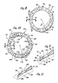
- Fig. 8 is a top plan view of an additional lens device according to the present invention.
- Fig. 9 is a cross-sectional view taken along line 9-9 in Fig. 8 showing the lens device attached to a cornea.
- Fig. 10 is a top plan view of a further lens device according to the present invention.
- Fig. 11 is a cross-sectional view taken along line 11-11 of Fig. 8 showing the lens device attached to a cornea.
- Referring now to the drawings, Figs. 1, 3 and 4 show a corneal onlay lens, shown generally at 10, attached to a
cornea 12. Lens 10 includes a central circular, opticallyclear optic 14, which is configured to correct the vision of the patient to whose cornea lens 10 is attached, and a flange or wing, shown generally at 16, which extends generally radially outwardly fromoptic 14 andradial axis 18 of lens 10. - More specifically, lens 10 is made, e.g., molded, as a unitary component of a synthetic polymeric material, e.g., polymethyl methacrylate.
Optic 14 includes ananterior surface 20 and aposterior surface 22, which abuts the upper or anterior surface 24 ofcornea 12. Upper surface 24 may not be the original or naturally occurring upper surface ofcornea 14. In order to prepare thecornea 14 for implantation of lens 10, the naturally occurring upper surface of thecornea 14 may be removed, e.g., abraded away. In any event, theposterior surface 22 ofoptic 14 abutscornea 12. - Flange 16 includes an
anterior surface 26, which is substantially a continuation ofanterior surface 20 ofoptic 14, aconcave bottom surface 28, a connectingsurface 30, and aposterior surface 32, which is substantially a continuation ofposterior surface 22 ofoptic 14.Anterior surface 26 andbottom surface 28 come together at edge orline 29, whilebottom surface 28 and connectingsurface 30 come together at edge orline 31. Connectingsurface 30 andposterior surface 32 come together at edge orline 34 and together form a generally V-shaped flute which extends generally inwardly towardradial axis 18. The angle defined by this flute, i.e., connectingsurface 30,line 34 andposterior surface 32, is more preferably in the range of about 30o to about 60o. - Lens 10 is attached to
cornea 12 as follows.Cornea 12 is prepared to receive lens 15 by cutting a circular groove incornea 12. This circular groove, the cutting of which can be accomplished by conventional and well known instruments, is preferably positioned at an angle extending outwardly from the center ofcornea 12. This groove forms anouter flap 36 of corneal tissue. A second circular groove is cut incornea 12, preferably positioned at an angle extending inwardly toward the center ofcornea 12. This second groove forms an inner flap 38 of corneal tissue. Further, it may be desireable to remove a quantity of corneal tissue from between these two grooves in order to better accommodate lens 10. Also, as noted previously, the original or naturally occurring outer surface, or portion thereof, ofcornea 12 may be removed in anticipation of attaching lens 10 tocornea 12. - Once
cornea 12 has been prepared, lens 10 is placed with respect tocornea 12 so thatanterior surface 26,bottom surface 28 and connectingsurface 30 of flange 16 a-re captured within the grooves cut incornea 12. This placement of lens is substantially as shown in Figs. 1 and 2. With lens 10 so placed,outer flap 36 overlaysanterior surface 26 and inner flap 38overlays connecting surface 30. This "double overlaying" arrangement provides for very effective initial and final attachment of lens 10 tocornea 12. In other words, this arrangement reduces, and may eliminate, the need for suturing lens 10 tocornea 12 at the time lens 10 is surgically associated withcornea 12 and provides resistance to forces tending to remove lens 10 fromcornea 12 after thecornea 12 has grown around lens 10. If desired, lens 10 may be sutured in place incornea 12, using conventional techniques. - The combination of the
outer flap 36 and inner flap 38 overlaying portions of flange 16 provides for resistance to forces both parallel to theradial axis 18 and substantially parallel toanterior surface 20 ofoptic 14 tending to displace or remove lens 10 fromcornea 12. Such forces may occur as the result of the blinking of an eyelid over lens 10, and/or the movements of the patient's head as he/she goes about every day activities. - Another corneal onlay lens, shown generally at 110, is illustrated in Fig. 5. Except as expressly set forth below,
lens 110 is structured, functions, and is attached to a cornea substantially similarly to lens 10, as described herein. Components oflens 110 which correspond to components of lens 10 are given corresponding reference numerals increased by 100. -
Corneal onlay lens 110, attached tocornea 112, includes a central, circular optic 114 and a flange shown generally at 116. The primary difference betweenlenses 10 and 110 is in the structure of the flange. Inlens 110, flange 116 includes ananterior surface 40, a firstinterior surface 42, and secondinterior surface 44 and aposterior surface 46.Anterior surface 40 and firstinterior surface 42 come together at edge orline 47. First and secondinterior surfaces line 48 and together form a generally in-shaped flute which extends generally outwardly away fromradial axis 118. The angle defined by this flute, i.e., firstinterior surface 42,line 48 and secondinterior surface 44, is more preferably in the range of about 30o to about 60o. Secondinterior surface 44 andposterior surface 46 come together at edge orline 49. The area of each of firstinterior surface 42 and secondinterior surface 44 is larger than the area of at least one surface in flange 116 parallel toradial axis 118 oflens 110. Also, the surface defined by lined 47 and 49 has an area larger than the area of at least one surface in flange 116 parallel toradial axis 118. -
Lens 110 is attached tocornea 112 as follows.Cornea 112 is prepared to receivelens 110 by cutting a circular groove incornea 112 which extends at an angle outwardly from the center ofcornea 112. This groove forms aflap 50 of corneal tissue. - Once
cornea 112 has been prepared,lens 110 is placed with respect tocornea 112 so that the leg of flange 116 defined by secondinterior surface 44 andposterior surface 46 is located in the groove previously cut. Firstinterior surface 42 is located in abutting relationship to the upper surface 124 ofcornea 112. This placement oflens 110 relative tocornea 112 is shown in Fig. 5. - With
lens 110 so placed,flap 50 overlays secondinterior surface 44 and is captured by the flute defined by first and secondinterior surfaces line 48. Withflap 50 being situated in this overlying and captured relationship very effective initial and final attachment oflens 110 tocornea 112 is provided. This arrangement reduces, and may eliminate, the need for suturing thelens 110 tocornea 112 during the surgical implantation. Aftercornea 112 grows around or adheres tolens 110, substantial resistance is provided against forces tending to removelens 110 fromcornea 112. Withflap 50 in the overlaying and captured relationship noted above, resistance to forces both parallel toradial axis 118 and substantially parallel toanterior surface 120 of optic 114 is provided. - Fig. 6 illustrates an alternate approach to attaching
lens 110 tocornea 112. In this approach,cornea 112 is prepared to receivelens 110 by cutting two circular grooves incornea 112 each of which extends at a different angle outwardly from the center ofcornea 112. These two grooves form an inner flap 52 of corneal tissue therebetween. In addition, the uppermost groove forms an outer flap 54 of corneal tissue. - Once
cornea 112 has been prepared,lens 110 is placed with respect tocornea 112 so that the leg of flange 116 defined byanterior surface 40 and firstinterior surface 42 is located in the uppermost groove and the leg of the flange 116 defined by secondinterior surface 44 andposterior surface 46 is located in the lowermost groove incornea 112. This placement oflens 110 relative tocornea 112 is shown in Fig. 6. - With
lens 110 so placed, outer flap 54 overlaysanterior surface 40 of flange 116 and inner flap 52 is captured by the flute defined by first and secondinterior surfaces line 48. The outer portion of flange 116 is completely surrounded by corneal tissue so that very effective initial and final attachment oflens 110 tocornea 112 is provided. This arrangement reduces, and may eliminate, the need for suturing thelens 110 tocornea 112 during surgical implantation. Aftercornea 112 grows -around or adheres tolens 110, substantial resistance is provided against forces tending to removelens 110 fromcornea 112. With.cornea 112 completely surrounding the outer portion of flange 116, as noted above, resistance to forces parallel toradial axis 118 and substantially parallel toanterior surface 112 of optic 114 tending to displace or removelens 110 fromcornea 112 is provided. - An alternate corneal onlay lens, shown generally at 210, is illustrated in Fig. 7. Except as expressly set forth below,
lens 210 is structured, functions and is attached to a cornea substantially similarly to lens 10, as described herein. Components oflens 210 which correspond to components of lens 10 are given corresponding reference numerals, increased by 200. - The primary difference between lens 10 and
lens 210 involves the structure of flange 216.Lens 210 includes a flange 216 which has an anterior surface 60, aposterior surface 62 and athird surface 64 which joins the other two surfaces. Thisthird surface 64 is generally frustoconical in configuration, extending generally away fromradial axis 218 going fromposterior surface 62 to anterior surface 60. In addition, the area of thisthird surface 64 is larger than the area of at least one surface in flange 216 parallel toradial axis 218. In the embodiment illustrated in Fig. 7, the areas of surfaces in flange 216 parallel tothird surface 64 progressively and substantially continuously increase so thatthird surface 64 itself has the largest area of any of such surfaces. -
Cornea 212 is prepared to receivelens 210 by cutting a scircular groove or grooves incornea 212. Further, it may be desirable to remove a quantity of corneal tissue adjacent to the groove or from between the grooves to better accommodatelens 210. In any event, such groove or grooves form a corneal flap 66. - Once
cornea 212 has been prepared,lens 210 is placed with respect tocornea 212 so that anterior surface 60,posterior surface 62 andthird surface 64 are captured within the groove or grooves cut incornea 212. This placement oflens 210 is substantially as shown in Fig. 6. Withlens 210 so placed, corneal flap 66 overlays anterior surface 60. This overlaying arrangement together with the frustoconical configuration of the relatively largethird surface 64 provides for very effective initial and final attachment oflens 210 tocornea 212. The need to suturelens 210 in place is reduced, and may be eliminated. The thus attachedlens 210 is resistant to displacement or removal fromcornea 212 by forces acting parallel to theradial axis 218 and substantially parallel to anterior surface 220 ofoptic 214. - Referring now to Figs. 8 and 9, an additional corneal onlay lens, shown generally at 70, includes a central
circular optic 72, a flange orwing 74 and aradial axis 76.Optic 72 is configured to correct the vision of the patient to whose cornea it is attached.Flange 74 extends generally radially outwardly fromoptic 72 andradial axis 76 oflens 70. -
Flange 74 includes a plurality of throughholes 78 or fenestrations which have substantially the same size, e.g., diameter, and are substantially uniformly spaced apart on, around,flange 74. Throughholes 78 are sized to allow or provide for the growth of corneal tissue therethrough. -
Lens 70 is made, e.g., molded, as a unitary component of a synthetic hydrogel-forming polymeric material, e.g., polyhydroxyethyl methacrylate. Such materials are very effective in producing corneal onlay lenses. One drawback that has occurred is that such hydrogel-forming materials tend to have reduced strength. This feature, in turn, makes attaching the lens to the cornea somewhat difficult. For example, sutures which are used to attach the lens to the cornea may break through the relatively weak hydrogel lens and become ineffective to hold the lens in place. - The
lens 70 overcomes these difficulties by providing aflange 74 which has increased unit strength relative to the optic 72. Withflange 74 being relatively strong, the likelihood of attaching sutures penetrating throughflange 72 is reduced. This, in turn, provides for more secure initial attachment oflens 70 to the cornea. - One particularly useful approach to providing a
flange 74 having increased unit strength is to selectively increase the cross-linking of the polymeric material making up theflange 70. Increasing the degree of cross-linking in flange can be achieved by chemical means, e.g., increasing the concentration of cross-linking components, e.g., multi-functional compounds, inflange 70, and/or by selectively subjectingflange 70 to radiation, e.g., ultraviolet light and/or gamma-ray radiation. In any event,flange 74 has increased unit strength relative tooptic 72.Flange 74 includes an anterior surface 80, aposterior surface 82, and anouter surface 84. - Referring to Fig. 9,
lens 70 is attached tocornea 86 as follows.Cornea 86 is prepared to receivelens 70 by cutting a circular groove incornea 86 which extends from theanterior surface 88 ofcornea 86 at an angle outwardly from the center ofcornea 86. This groove forms a flap 89 of cornea tissue. - Once
cornea 86 has been prepared,lens 70 is placed with respect tocornea 86 so thatflange 74, and in particular each of the throughholes 78; is located in the groove. In this manner, flap 89 overlays each of the through holes 78. This placement oflens 70 relative tocornea 86 is as shown in Fig. 9. - With
lens 70 so placed, flap 89overlays flange 74 and throughholes 78. Using conventional techniques,lens 70 is sutured in place by a plurality ofindividual sutures 90, one of which is illustrated in Fig. 9. Eachsuture 90 is passed through flap 89 and a throughhole 78. Thesuture 90 is then passed below theposterior surface 82 offlange 74 and up out of theanterior surface 88 ofcornea 86. The two ends ofsuture 90 are then tied together. - This suturing provides for secure initial attachment of
lens 70 tocornea 86. Further, the overlaying relation of flap 89 to flange 74 provides additional protection or resistance against forces, both parallel to the radial axis 71 oflens 70 and substantially parallel to the anterior surface 92 ofoptic 72, tending to displace or removelens 70 fromcornea 86. - After the initial attachment of
lens 70 tocornea 86, a period of healing ensues. During this period, corneal tissue grows into and through each of the through holes 78. This growth, in effect, connects flap 89 to the main body ofcornea 86 through throughhole 78. After such growth,cornea 86 effectively has grown aroundflange 74 and provides for very effective permanent attachment oflens 70 tocornea 86. Thus, after thesutures 90 are removed,lens 70 is securely attached tocornea 86 and is resistant to being displaced or removed by forces, e.g., from directions as described above. - A further corneal onlay lens, shown generally at 170, is illustrated in Figs. 10 and 11. Except as expressly set forth below
lens 170 is structured, functions and is attached to a cornea substantially similarly tolens 70, as described herein. components oflens 170 which correspond to components oflens 70 are given corresponding reference numerals increased by 100. - The primary difference between
lens 70 andlens 170 involves the structure offlange 174. Inlens 170,flange 174 includes a plurality ofareas 94 of reduced thickness extending between each of the throughholes 178 and theouter surface 184. Each of theseareas 94 extends downwardly from theanterior surface 180 offlange 174. This allows relatively easy access tosuch areas 94 should buch access become necessary, as described below. -
Areas 94 of reduced thickness also have reduced strength relative to the rest or remainder of thesolid flange 174.Such areas 94 make it more easy to removelens 170 fromcornea 186 when necessary. To illustrate, when it is desired to removelens 170 fromcornea 186,areas 94 can be relatively easily cut or torn to facilitate this removal. Thus,lens 170 provides substantially all of the advantages oflens 70, e.g., as described herein, and, in addition, provides for relatively easy surgical removal fromcornea 186, should such removal become necessary or desirable. - While this invention has been described with respect to various specific examples and embodiments, it is to be understood that the invention is not limited thereto and that it can be variously practiced within the scope of the following claims.
Claims (10)
1. A lens device for attachment to a cornea, said lens device comprising:
an optic having an optical axis;
a flange coupled to the optic and extending radially outwardly of the optic;
said flange including first and second radially extending projections adapted for use in attaching the lens device to the cornea, portions of said projections lying in the same radial plane and on the same side of the optical axis; and
said first projection extending radially outwardly.
2. A lens device as described in claim 1 wherein said second projection extends radially outwardly.
3. A lens device as described in claims 1 or 2 wherein the first and second projections define a generally V-shaped flute which opens radially outwardly.
4. A lens device as described in claims 1, 2 or 3 wherein the flange circumscribes the optic and has an anterior surface on an anterior side of the first projection, a first inner surface on a posterior side of first projection, a second inner surface on an anterior side of the second projection and a posterior surface on a posterior side of the second projection.
5. A lens device as described in claim 1 wherein the second projection extends radially inwardly.
6. A lens device as described in claim 5 wherein the flange has a posterior surface and the second projection and the posterior surface define a V-shaped flute which opens radially inwardly.
7. A lens device as described in claim 5 wherein the flange circumscribes the optic and the optic has an anterior surface, the flange has an anterior surface which is a continuation of the anterior surface of the optic, first and second posterior surfaces axially offset from each other and a connecting surface between the first and second posterior surfaces, the optic has a posterior surface and the second posterior surface forms a continuation of the posterior surface of the optic, said anterior surface of the flange and the first posterior surface; defining the first projection and the connecting surface and the first posterior surface defining the second projection, the connecting surface and the second posterior surface defining an angle of less than about 90 degrees.
8. A lens device for attachment to the cornea of a patient comprising:
an optic for correction of the patient's vision;
a flange affixed to and radially extending from said optic, said flange having an increased unit strength relative to said optic; and
at least one through hole in said flange sized and adapted to provide for growth of corneal tissue therethrough.
an optic for correction of the patient's vision;
a flange affixed to and radially extending from said optic, said flange having an increased unit strength relative to said optic; and
at least one through hole in said flange sized and adapted to provide for growth of corneal tissue therethrough.
9. A lens device as described in claim 8 wherein the optic and flange are made of a synthetic polymeric material and the flange is conditioned to increase its strength.
10. A device as described in claim 9 wherein there are a plurality of through holes in said flange, said flange has an outer periphery and includes a plurality of areas of reduced strength located between said through holes and said outer periphery of said flange and said flange is conditioned to increase the degree of cross-linking of said synthetic polymeric material in said flange.
Applications Claiming Priority (2)
| Application Number | Priority Date | Filing Date | Title |
|---|---|---|---|
| US07/440,975 US5019097A (en) | 1989-11-22 | 1989-11-22 | Corneal onlay lenses and methods for attaching same |
| US440975 | 1989-11-22 |
Publications (2)
| Publication Number | Publication Date |
|---|---|
| EP0434205A2 true EP0434205A2 (en) | 1991-06-26 |
| EP0434205A3 EP0434205A3 (en) | 1991-09-18 |
Family
ID=23750981
Family Applications (1)
| Application Number | Title | Priority Date | Filing Date |
|---|---|---|---|
| EP19900312413 Withdrawn EP0434205A3 (en) | 1989-11-22 | 1990-11-14 | Corneal onlay lenses and methods for attaching same |
Country Status (3)
| Country | Link |
|---|---|
| US (1) | US5019097A (en) |
| EP (1) | EP0434205A3 (en) |
| JP (1) | JPH03173560A (en) |
Cited By (13)
| Publication number | Priority date | Publication date | Assignee | Title |
|---|---|---|---|---|
| WO2009145842A2 (en) * | 2008-04-04 | 2009-12-03 | Forsight Labs, Llc | Therapeutic device for pain management and vision |
| WO2009146151A2 (en) * | 2008-04-04 | 2009-12-03 | Forsight Labs, Llc | Corneal onlay devices and methods |
| US8459793B2 (en) | 2009-10-23 | 2013-06-11 | Nexisvision, Inc. | Conformable therapeutic shield for vision and pain |
| US8591025B1 (en) | 2012-09-11 | 2013-11-26 | Nexisvision, Inc. | Eye covering and refractive correction methods for LASIK and other applications |
| US8678584B2 (en) | 2012-04-20 | 2014-03-25 | Nexisvision, Inc. | Contact lenses for refractive correction |
| US8864306B2 (en) | 2011-04-28 | 2014-10-21 | Nexisvision, Inc. | Eye covering and refractive correction methods and apparatus having improved tear flow, comfort, and/or applicability |
| US9341864B2 (en) | 2013-11-15 | 2016-05-17 | Nexisvision, Inc. | Contact lenses having a reinforcing scaffold |
| US9395558B2 (en) | 2010-10-25 | 2016-07-19 | Nexisvision, Inc. | Methods and apparatus to identify eye coverings for vision |
| US9423632B2 (en) | 2012-04-20 | 2016-08-23 | Nexisvision, Inc. | Contact lenses for refractive correction |
| US9465233B2 (en) | 2012-04-20 | 2016-10-11 | Nexisvision, Inc. | Bimodular contact lenses |
| US9740026B2 (en) | 2013-06-26 | 2017-08-22 | Nexisvision, Inc. | Contact lenses for refractive correction |
| US10191303B2 (en) | 2014-01-29 | 2019-01-29 | Nexisvision, Inc. | Multifocal bimodulus contact lenses |
| US10596038B2 (en) | 2009-10-23 | 2020-03-24 | Journey1, Inc. | Corneal denervation for treatment of ocular pain |
Families Citing this family (50)
| Publication number | Priority date | Publication date | Assignee | Title |
|---|---|---|---|---|
| FR2675038B3 (en) * | 1991-04-10 | 1993-07-16 | France Chirurgie Instrumentation | MESOPROSTHESIS SUPPORT. |
| US5300115A (en) * | 1992-11-19 | 1994-04-05 | Keratos, Inc. | Intraocular prosthesis |
| US5502518A (en) * | 1993-09-09 | 1996-03-26 | Scient Optics Inc | Asymmetric aspheric contact lens |
| WO1995028897A2 (en) * | 1994-04-19 | 1995-11-02 | Mcdonald Henry H | Lens insertable between the iris and the natural lens |
| EP1173790A2 (en) * | 1999-03-01 | 2002-01-23 | Boston Innovative Optics, Inc. | System and method for increasing the depth of focus of the human eye |
| US6197058B1 (en) | 1999-03-22 | 2001-03-06 | Valdemar Portney | Corrective intraocular lens system and intraocular lenses and lens handling device therefor |
| US6616693B1 (en) | 2000-05-03 | 2003-09-09 | Advanced Medical Optics, Inc. | Flexible fixation members for angle-supported anterior chamber intraocular lenses |
| US6592621B1 (en) * | 2000-11-10 | 2003-07-15 | Rudolph S. Domino | Flexible intra-ocular lens of variable focus |
| US6482229B1 (en) | 2000-11-21 | 2002-11-19 | Advanced Medical Optics, Inc. | Anterior chamber intraocular lens having fixation members attached to the cornea and methods of implantation |
| US6733526B2 (en) | 2002-04-25 | 2004-05-11 | Advanced Medical Optics, Inc. | Method of improving adherence and centering of intra-corneal implants on corneal bed |
| EP1549255A4 (en) * | 2002-09-13 | 2007-12-19 | Coopervision Inc | Devices and methods for improving vision |
| WO2004028410A1 (en) * | 2002-09-24 | 2004-04-08 | Lions Eye Institute Limited | Biointegrable keratoprosthesis |
| US20040068317A1 (en) * | 2002-10-07 | 2004-04-08 | Knight Patricia M. | Anterior chamber intraocular lens with size and position indicators |
| US6991651B2 (en) * | 2002-11-27 | 2006-01-31 | Valdemar Portney | Adjustable intraocular lens system and intraocular lenses therefor |
| US7303582B2 (en) * | 2003-03-21 | 2007-12-04 | Advanced Medical Optics, Inc. | Foldable angle-fixated intraocular lens |
| US7628810B2 (en) | 2003-05-28 | 2009-12-08 | Acufocus, Inc. | Mask configured to maintain nutrient transport without producing visible diffraction patterns |
| US20050046794A1 (en) | 2003-06-17 | 2005-03-03 | Silvestrini Thomas A. | Method and apparatus for aligning a mask with the visual axis of an eye |
| US20050178394A1 (en) * | 2003-08-21 | 2005-08-18 | Intralens Vision, Inc. | Method for keratophakia surgery |
| EP1771131A2 (en) | 2004-05-20 | 2007-04-11 | CooperVision Inc. | Corneal onlays and wavefront aberration correction to enhance vision |
| CA2577025C (en) * | 2004-08-13 | 2014-01-28 | Ottawa Health Research Institute | Vision enhancing ophthalmic devices and related methods and compositions |
| US7976577B2 (en) | 2005-04-14 | 2011-07-12 | Acufocus, Inc. | Corneal optic formed of degradation resistant polymer |
| WO2007092550A2 (en) * | 2006-02-08 | 2007-08-16 | Coopervision Inc. | Corneal onlays and related methods |
| US7883520B2 (en) * | 2006-04-10 | 2011-02-08 | Forsight Labs, Llc | Corneal epithelial pocket formation systems, components and methods |
| EP2129345B8 (en) | 2007-03-13 | 2014-07-09 | Optimedica Corporation | Apparatus for creating ocular surgical and relaxing incisions |
| US7993398B2 (en) * | 2007-04-24 | 2011-08-09 | Abbott Medical Optics Inc. | Angle indicator for capsular bag size measurement |
| US9216080B2 (en) | 2007-08-27 | 2015-12-22 | Amo Groningen B.V. | Toric lens with decreased sensitivity to cylinder power and rotation and method of using the same |
| US8974526B2 (en) * | 2007-08-27 | 2015-03-10 | Amo Groningen B.V. | Multizonal lens with extended depth of focus |
| US8142423B2 (en) * | 2007-11-07 | 2012-03-27 | Amo Development, Llc. | System and method for incising material |
| AU2009214036B2 (en) | 2008-02-15 | 2014-04-17 | Amo Regional Holdings | System, ophthalmic lens, and method for extending depth of focus |
| US8439498B2 (en) | 2008-02-21 | 2013-05-14 | Abbott Medical Optics Inc. | Toric intraocular lens with modified power characteristics |
| AU2009228146B2 (en) | 2008-03-28 | 2015-06-04 | Johnson & Johnson Surgical Vision, Inc. | Systems for ocular measurements |
| US8444267B2 (en) | 2009-12-18 | 2013-05-21 | Amo Groningen B.V. | Ophthalmic lens, systems and methods with angular varying phase delay |
| US8862447B2 (en) | 2010-04-30 | 2014-10-14 | Amo Groningen B.V. | Apparatus, system and method for predictive modeling to design, evaluate and optimize ophthalmic lenses |
| US20100087920A1 (en) * | 2008-10-07 | 2010-04-08 | Forsight Labs, Llc | Corneal Onlay Lenses and Related Methods for Improving Vision of Presbyopic Patients |
| RU2012108951A (en) | 2009-08-13 | 2013-09-20 | Акуфокус, Инк. | HIDDED INTRAOCULAR IMPLANTS AND LENSES |
| USD656526S1 (en) | 2009-11-10 | 2012-03-27 | Acufocus, Inc. | Ocular mask |
| EP2646872A1 (en) | 2010-12-01 | 2013-10-09 | AMO Groningen B.V. | A multifocal lens having an optical add power progression, and a system and method of providing same |
| EP2785296B1 (en) | 2011-12-02 | 2018-06-20 | AcuFocus, Inc. | Ocular mask having selective spectral transmission |
| WO2014039495A1 (en) | 2012-09-05 | 2014-03-13 | University Of Miami | Novel keratoprosthesis, and system and method of corneal repair using same |
| WO2014087249A2 (en) | 2012-12-04 | 2014-06-12 | Amo Groningen B.V. | Lenses systems and methods for providing binocular customized treatments to correct presbyopia |
| US9204962B2 (en) | 2013-03-13 | 2015-12-08 | Acufocus, Inc. | In situ adjustable optical mask |
| US9427922B2 (en) | 2013-03-14 | 2016-08-30 | Acufocus, Inc. | Process for manufacturing an intraocular lens with an embedded mask |
| AU2017218680B2 (en) | 2016-02-09 | 2021-09-23 | Amo Groningen B.V. | Progressive power intraocular lens, and methods of use and manufacture |
| AU2017237090B2 (en) | 2016-03-23 | 2021-10-21 | Johnson & Johnson Surgical Vision, Inc. | Ophthalmic apparatus with corrective meridians having extended tolerance band by modifying refractive powers in uniform meridian distribution |
| WO2017165623A1 (en) | 2016-03-23 | 2017-09-28 | Abbott Medical Optics Inc. | Power calculator for an ophthalmic apparatus with corrective meridians having extended tolerance or operation band |
| EP3490497A4 (en) * | 2016-07-26 | 2020-03-25 | Singapore Health Services Pte Ltd | Optical cylinder and method of surface treatment of the same |
| AU2017352030B2 (en) | 2016-10-25 | 2023-03-23 | Amo Groningen B.V. | Realistic eye models to design and evaluate intraocular lenses for a large field of view |
| US10739227B2 (en) | 2017-03-23 | 2020-08-11 | Johnson & Johnson Surgical Vision, Inc. | Methods and systems for measuring image quality |
| US11282605B2 (en) | 2017-11-30 | 2022-03-22 | Amo Groningen B.V. | Intraocular lenses that improve post-surgical spectacle independent and methods of manufacturing thereof |
| US11886046B2 (en) | 2019-12-30 | 2024-01-30 | Amo Groningen B.V. | Multi-region refractive lenses for vision treatment |
Citations (4)
| Publication number | Priority date | Publication date | Assignee | Title |
|---|---|---|---|---|
| US2952023A (en) * | 1957-03-19 | 1960-09-13 | Rosen Hyman | Corneal fabrication |
| US4810082A (en) * | 1987-07-01 | 1989-03-07 | Abel Robert Jr | Corneal onlay lens |
| WO1989005128A1 (en) * | 1987-12-09 | 1989-06-15 | White Thomas C | Corneal implant |
| EP0404689A1 (en) * | 1989-06-23 | 1990-12-27 | Khalil Hanna | Lens for epikeratophakia and keratotome intended for the creation of an incision for implantation of such a lens |
Family Cites Families (19)
| Publication number | Priority date | Publication date | Assignee | Title |
|---|---|---|---|---|
| US2714721A (en) * | 1953-01-23 | 1955-08-09 | Jr William Stone | Artificial corneal implants |
| US3866249A (en) * | 1974-03-07 | 1975-02-18 | Leonard Flom | Posterior chamber artificial intraocular lens |
| DE2639419C2 (en) * | 1975-09-22 | 1986-04-17 | AO Inc., Southbridge, Mass. | Artificial intraocular lens and method of making |
| US4338687A (en) * | 1980-10-14 | 1982-07-13 | Rainin Edgar A | Intraocular lens with spring mechanism |
| US4346482A (en) * | 1981-01-22 | 1982-08-31 | Tennant Jerald L | Living contact lens |
| US4573998A (en) * | 1982-02-05 | 1986-03-04 | Staar Surgical Co. | Methods for implantation of deformable intraocular lenses |
| US4468820A (en) * | 1982-05-10 | 1984-09-04 | Precision-Cosmet Co., Inc. | Haptic attachment for intraocular lenses |
| US4485499A (en) * | 1982-09-02 | 1984-12-04 | Castleman Lawrence D | Intraocular posterior chamber lens |
| US4547914A (en) * | 1982-09-02 | 1985-10-22 | Castleman Lawrence D | Intraocular posterior chamber lens |
| US4524468A (en) * | 1983-05-13 | 1985-06-25 | Kelman Charles D | Intraocular lenses |
| US4615702A (en) * | 1984-09-10 | 1986-10-07 | Koziol Jeffrey E | Intraocular lens and method of forming the lens |
| US4646720A (en) * | 1985-03-12 | 1987-03-03 | Peyman Gholam A | Optical assembly permanently attached to the cornea |
| US4737322A (en) * | 1985-09-27 | 1988-04-12 | Staar Surgical Company | Intraocular lens structure with polyimide haptic portion and methods for fabrication |
| US4668446A (en) * | 1985-09-27 | 1987-05-26 | Cilco, Inc. | Process for making soft contact and intraocular lenses with an esterifiable carboxyl-containing polymer |
| US4834751A (en) * | 1985-12-04 | 1989-05-30 | Allergan, Inc. | Staking ring for soft IOL |
| US4790846A (en) * | 1985-12-09 | 1988-12-13 | Allergan Pharmaceuticals, Inc. | Haptic to optic attachment for a soft IOL |
| US4693715A (en) * | 1986-06-19 | 1987-09-15 | Abel Robert Jr | Artificial cornea |
| US4842599A (en) * | 1986-10-28 | 1989-06-27 | Ann M. Bronstein | Prosthetic cornea and method of implantation therefor |
| US4923467A (en) * | 1988-03-02 | 1990-05-08 | Thompson Keith P | Apparatus and process for application and adjustable reprofiling of synthetic lenticules for vision correction |
-
1989
- 1989-11-22 US US07/440,975 patent/US5019097A/en not_active Expired - Fee Related
-
1990
- 1990-11-14 EP EP19900312413 patent/EP0434205A3/en not_active Withdrawn
- 1990-11-21 JP JP2317634A patent/JPH03173560A/en active Pending
Patent Citations (4)
| Publication number | Priority date | Publication date | Assignee | Title |
|---|---|---|---|---|
| US2952023A (en) * | 1957-03-19 | 1960-09-13 | Rosen Hyman | Corneal fabrication |
| US4810082A (en) * | 1987-07-01 | 1989-03-07 | Abel Robert Jr | Corneal onlay lens |
| WO1989005128A1 (en) * | 1987-12-09 | 1989-06-15 | White Thomas C | Corneal implant |
| EP0404689A1 (en) * | 1989-06-23 | 1990-12-27 | Khalil Hanna | Lens for epikeratophakia and keratotome intended for the creation of an incision for implantation of such a lens |
Cited By (29)
| Publication number | Priority date | Publication date | Assignee | Title |
|---|---|---|---|---|
| US9943401B2 (en) | 2008-04-04 | 2018-04-17 | Eugene de Juan, Jr. | Therapeutic device for pain management and vision |
| WO2009146151A2 (en) * | 2008-04-04 | 2009-12-03 | Forsight Labs, Llc | Corneal onlay devices and methods |
| WO2009146151A3 (en) * | 2008-04-04 | 2010-01-14 | Forsight Labs, Llc | Corneal onlay devices and methods |
| WO2009145842A3 (en) * | 2008-04-04 | 2010-01-28 | Forsight Labs, Llc | Therapeutic device for pain management and vision |
| US10555804B2 (en) | 2008-04-04 | 2020-02-11 | Journey1, Inc. | Therapeutic device for pain management and vision |
| WO2009145842A2 (en) * | 2008-04-04 | 2009-12-03 | Forsight Labs, Llc | Therapeutic device for pain management and vision |
| US8926096B2 (en) | 2009-10-23 | 2015-01-06 | Nexisvision, Inc. | Conformable therapeutic shield for vision and pain |
| US10663761B2 (en) | 2009-10-23 | 2020-05-26 | Journey1, Inc. | Conformable therapeutic shield for vision and pain |
| US9107773B2 (en) | 2009-10-23 | 2015-08-18 | Nexisvision, Inc. | Conformable therapeutic shield for vision and pain |
| US9241837B2 (en) | 2009-10-23 | 2016-01-26 | Nexisvision, Inc. | Conformable therapeutic shield for vision and pain |
| US10627649B2 (en) | 2009-10-23 | 2020-04-21 | Journey1, Inc. | Conformable therapeutic shield for vision and pain |
| US10596038B2 (en) | 2009-10-23 | 2020-03-24 | Journey1, Inc. | Corneal denervation for treatment of ocular pain |
| US9498385B2 (en) | 2009-10-23 | 2016-11-22 | Nexisvision, Inc. | Conformable therapeutic shield for vision and pain |
| US8459793B2 (en) | 2009-10-23 | 2013-06-11 | Nexisvision, Inc. | Conformable therapeutic shield for vision and pain |
| US9810921B2 (en) | 2009-10-23 | 2017-11-07 | Nexisvision, Inc. | Conformable therapeutic shield for vision and pain |
| US9395558B2 (en) | 2010-10-25 | 2016-07-19 | Nexisvision, Inc. | Methods and apparatus to identify eye coverings for vision |
| US8864306B2 (en) | 2011-04-28 | 2014-10-21 | Nexisvision, Inc. | Eye covering and refractive correction methods and apparatus having improved tear flow, comfort, and/or applicability |
| US11126011B2 (en) | 2011-04-28 | 2021-09-21 | Journey1, Inc. | Contact lenses for refractive correction |
| US9740025B2 (en) | 2011-04-28 | 2017-08-22 | Nexisvision, Inc. | Eye covering and refractive correction methods and apparatus having improved tear flow, comfort, and/or applicability |
| US9465233B2 (en) | 2012-04-20 | 2016-10-11 | Nexisvision, Inc. | Bimodular contact lenses |
| US10036900B2 (en) | 2012-04-20 | 2018-07-31 | Nexisvision, Inc. | Bimodular contact lenses |
| US9423632B2 (en) | 2012-04-20 | 2016-08-23 | Nexisvision, Inc. | Contact lenses for refractive correction |
| US8678584B2 (en) | 2012-04-20 | 2014-03-25 | Nexisvision, Inc. | Contact lenses for refractive correction |
| US10039671B2 (en) | 2012-09-11 | 2018-08-07 | Nexisvision, Inc. | Eye covering and refractive correction methods for lasik and other applications |
| US8591025B1 (en) | 2012-09-11 | 2013-11-26 | Nexisvision, Inc. | Eye covering and refractive correction methods for LASIK and other applications |
| US9740026B2 (en) | 2013-06-26 | 2017-08-22 | Nexisvision, Inc. | Contact lenses for refractive correction |
| US9851586B2 (en) | 2013-11-15 | 2017-12-26 | Nexisvision, Inc. | Contact lenses having a reinforcing scaffold |
| US9341864B2 (en) | 2013-11-15 | 2016-05-17 | Nexisvision, Inc. | Contact lenses having a reinforcing scaffold |
| US10191303B2 (en) | 2014-01-29 | 2019-01-29 | Nexisvision, Inc. | Multifocal bimodulus contact lenses |
Also Published As
| Publication number | Publication date |
|---|---|
| EP0434205A3 (en) | 1991-09-18 |
| JPH03173560A (en) | 1991-07-26 |
| US5019097A (en) | 1991-05-28 |
Similar Documents
| Publication | Publication Date | Title |
|---|---|---|
| US5019097A (en) | Corneal onlay lenses and methods for attaching same | |
| US4693715A (en) | Artificial cornea | |
| US5489301A (en) | Corneal prosthesis | |
| US4563779A (en) | Corneal implant and method of making the same | |
| EP0670701B1 (en) | Intraocular prosthesis | |
| US4470159A (en) | Keratoprosthesis | |
| CA1164602A (en) | Posterior chamber intraocular lens | |
| US4612012A (en) | Corneal implant | |
| AU667342B2 (en) | Corneal ring inlay and methods of use | |
| US4851003A (en) | Corneal implant lens with fixation holes | |
| US4485499A (en) | Intraocular posterior chamber lens | |
| US4715858A (en) | Epicorneal lens | |
| EP1021142B1 (en) | Segmented scleral band for treatment of presbyopia and other eye disorders | |
| US5258025A (en) | Corrective intraocular lens | |
| US4810082A (en) | Corneal onlay lens | |
| US4586929A (en) | Hydrogel keratoprosthesis | |
| DE3326341A1 (en) | IMPROVED FIXING SYSTEM FOR INTRAOCULAR LENSES | |
| US4268921A (en) | Intraocular lenses | |
| CA2441734C (en) | Implant for altering the iris color and method of locating and fixing an implant for altering the iris color | |
| CA1262803A (en) | Intraocular lens with ridges | |
| CA2515720A1 (en) | Teledioptic lens system and method for using the same | |
| US20050177231A1 (en) | Intra-ocular implant promoting direction guided cell growth | |
| US4547915A (en) | Intraocular posterior chamber lens | |
| US4316291A (en) | Intraocular lens structure | |
| US4743255A (en) | Radiopaque intra-ocular lens implant |
Legal Events
| Date | Code | Title | Description |
|---|---|---|---|
| PUAI | Public reference made under article 153(3) epc to a published international application that has entered the european phase |
Free format text: ORIGINAL CODE: 0009012 |
|
| AK | Designated contracting states |
Kind code of ref document: A2 Designated state(s): DE FR GB IT |
|
| PUAL | Search report despatched |
Free format text: ORIGINAL CODE: 0009013 |
|
| AK | Designated contracting states |
Kind code of ref document: A3 Designated state(s): DE FR GB IT |
|
| STAA | Information on the status of an ep patent application or granted ep patent |
Free format text: STATUS: THE APPLICATION IS DEEMED TO BE WITHDRAWN |
|
| 18D | Application deemed to be withdrawn |
Effective date: 19920319 |