EP0433649A1 - Fluid metering pump - Google Patents
Fluid metering pump Download PDFInfo
- Publication number
- EP0433649A1 EP0433649A1 EP19900121666 EP90121666A EP0433649A1 EP 0433649 A1 EP0433649 A1 EP 0433649A1 EP 19900121666 EP19900121666 EP 19900121666 EP 90121666 A EP90121666 A EP 90121666A EP 0433649 A1 EP0433649 A1 EP 0433649A1
- Authority
- EP
- European Patent Office
- Prior art keywords
- metering pump
- pump according
- shaped
- seat
- constituted
- Prior art date
- Legal status (The legal status is an assumption and is not a legal conclusion. Google has not performed a legal analysis and makes no representation as to the accuracy of the status listed.)
- Withdrawn
Links
Images


Classifications
-
- F—MECHANICAL ENGINEERING; LIGHTING; HEATING; WEAPONS; BLASTING
- F04—POSITIVE - DISPLACEMENT MACHINES FOR LIQUIDS; PUMPS FOR LIQUIDS OR ELASTIC FLUIDS
- F04B—POSITIVE-DISPLACEMENT MACHINES FOR LIQUIDS; PUMPS
- F04B53/00—Component parts, details or accessories not provided for in, or of interest apart from, groups F04B1/00 - F04B23/00 or F04B39/00 - F04B47/00
- F04B53/10—Valves; Arrangement of valves
- F04B53/1037—Flap valves
- F04B53/1047—Flap valves the valve being formed by one or more flexible elements
- F04B53/106—Flap valves the valve being formed by one or more flexible elements the valve being a membrane
- F04B53/1067—Flap valves the valve being formed by one or more flexible elements the valve being a membrane fixed at its whole periphery and with an opening at its centre
-
- F—MECHANICAL ENGINEERING; LIGHTING; HEATING; WEAPONS; BLASTING
- F04—POSITIVE - DISPLACEMENT MACHINES FOR LIQUIDS; PUMPS FOR LIQUIDS OR ELASTIC FLUIDS
- F04B—POSITIVE-DISPLACEMENT MACHINES FOR LIQUIDS; PUMPS
- F04B13/00—Pumps specially modified to deliver fixed or variable measured quantities
-
- F—MECHANICAL ENGINEERING; LIGHTING; HEATING; WEAPONS; BLASTING
- F04—POSITIVE - DISPLACEMENT MACHINES FOR LIQUIDS; PUMPS FOR LIQUIDS OR ELASTIC FLUIDS
- F04B—POSITIVE-DISPLACEMENT MACHINES FOR LIQUIDS; PUMPS
- F04B17/00—Pumps characterised by combination with, or adaptation to, specific driving engines or motors
- F04B17/03—Pumps characterised by combination with, or adaptation to, specific driving engines or motors driven by electric motors
-
- F—MECHANICAL ENGINEERING; LIGHTING; HEATING; WEAPONS; BLASTING
- F04—POSITIVE - DISPLACEMENT MACHINES FOR LIQUIDS; PUMPS FOR LIQUIDS OR ELASTIC FLUIDS
- F04B—POSITIVE-DISPLACEMENT MACHINES FOR LIQUIDS; PUMPS
- F04B53/00—Component parts, details or accessories not provided for in, or of interest apart from, groups F04B1/00 - F04B23/00 or F04B39/00 - F04B47/00
- F04B53/10—Valves; Arrangement of valves
- F04B53/1037—Flap valves
- F04B53/1047—Flap valves the valve being formed by one or more flexible elements
- F04B53/1052—Flap valves the valve being formed by one or more flexible elements two flexible elements oscillating around a fixed point
-
- F—MECHANICAL ENGINEERING; LIGHTING; HEATING; WEAPONS; BLASTING
- F04—POSITIVE - DISPLACEMENT MACHINES FOR LIQUIDS; PUMPS FOR LIQUIDS OR ELASTIC FLUIDS
- F04B—POSITIVE-DISPLACEMENT MACHINES FOR LIQUIDS; PUMPS
- F04B53/00—Component parts, details or accessories not provided for in, or of interest apart from, groups F04B1/00 - F04B23/00 or F04B39/00 - F04B47/00
- F04B53/10—Valves; Arrangement of valves
- F04B53/109—Valves; Arrangement of valves inlet and outlet valve forming one unit
- F04B53/1092—Valves; Arrangement of valves inlet and outlet valve forming one unit and one single element forming both the inlet and outlet closure member
-
- F—MECHANICAL ENGINEERING; LIGHTING; HEATING; WEAPONS; BLASTING
- F04—POSITIVE - DISPLACEMENT MACHINES FOR LIQUIDS; PUMPS FOR LIQUIDS OR ELASTIC FLUIDS
- F04B—POSITIVE-DISPLACEMENT MACHINES FOR LIQUIDS; PUMPS
- F04B9/00—Piston machines or pumps characterised by the driving or driven means to or from their working members
- F04B9/02—Piston machines or pumps characterised by the driving or driven means to or from their working members the means being mechanical
-
- H—ELECTRICITY
- H02—GENERATION; CONVERSION OR DISTRIBUTION OF ELECTRIC POWER
- H02K—DYNAMO-ELECTRIC MACHINES
- H02K21/00—Synchronous motors having permanent magnets; Synchronous generators having permanent magnets
- H02K21/12—Synchronous motors having permanent magnets; Synchronous generators having permanent magnets with stationary armatures and rotating magnets
- H02K21/14—Synchronous motors having permanent magnets; Synchronous generators having permanent magnets with stationary armatures and rotating magnets with magnets rotating within the armatures
- H02K21/18—Synchronous motors having permanent magnets; Synchronous generators having permanent magnets with stationary armatures and rotating magnets with magnets rotating within the armatures having horse-shoe armature cores
- H02K21/185—Synchronous motors having permanent magnets; Synchronous generators having permanent magnets with stationary armatures and rotating magnets with magnets rotating within the armatures having horse-shoe armature cores with the axis of the rotor perpendicular to the plane of the armature
-
- H—ELECTRICITY
- H02—GENERATION; CONVERSION OR DISTRIBUTION OF ELECTRIC POWER
- H02K—DYNAMO-ELECTRIC MACHINES
- H02K7/00—Arrangements for handling mechanical energy structurally associated with dynamo-electric machines, e.g. structural association with mechanical driving motors or auxiliary dynamo-electric machines
- H02K7/10—Structural association with clutches, brakes, gears, pulleys or mechanical starters
- H02K7/118—Structural association with clutches, brakes, gears, pulleys or mechanical starters with starting devices
-
- Y—GENERAL TAGGING OF NEW TECHNOLOGICAL DEVELOPMENTS; GENERAL TAGGING OF CROSS-SECTIONAL TECHNOLOGIES SPANNING OVER SEVERAL SECTIONS OF THE IPC; TECHNICAL SUBJECTS COVERED BY FORMER USPC CROSS-REFERENCE ART COLLECTIONS [XRACs] AND DIGESTS
- Y10—TECHNICAL SUBJECTS COVERED BY FORMER USPC
- Y10T—TECHNICAL SUBJECTS COVERED BY FORMER US CLASSIFICATION
- Y10T137/00—Fluid handling
- Y10T137/7722—Line condition change responsive valves
- Y10T137/7837—Direct response valves [i.e., check valve type]
- Y10T137/7838—Plural
- Y10T137/7843—Integral resilient member forms plural valves
-
- Y—GENERAL TAGGING OF NEW TECHNOLOGICAL DEVELOPMENTS; GENERAL TAGGING OF CROSS-SECTIONAL TECHNOLOGIES SPANNING OVER SEVERAL SECTIONS OF THE IPC; TECHNICAL SUBJECTS COVERED BY FORMER USPC CROSS-REFERENCE ART COLLECTIONS [XRACs] AND DIGESTS
- Y10—TECHNICAL SUBJECTS COVERED BY FORMER USPC
- Y10T—TECHNICAL SUBJECTS COVERED BY FORMER US CLASSIFICATION
- Y10T137/00—Fluid handling
- Y10T137/7722—Line condition change responsive valves
- Y10T137/7837—Direct response valves [i.e., check valve type]
- Y10T137/7879—Resilient material valve
- Y10T137/7888—With valve member flexing about securement
Definitions
- the present invention relates to a fluid metering pump.
- washing machines are currently provided with devices for metering the powder detergent during the various washing steps which are absolutely unsuitable for being used with liquid detergent.
- Said metering devices are in fact generally constituted by small compartments into which the powder detergent is poured; the detergent is gradually dissolved by a current of water which is caused to flow, when required, in said compartments.
- a dose of liquid detergent poured into said compartments would end up completely inside the washing containers upon the first flow of the water current.
- Dosage containers to be inserted inside the washing tumbler, among the washing, are currently used for the dosage of liquid detergents.
- Said dosage containers have an appropriate opening out of which the detergent flows during the washing cycle.
- the aim of the present invention is to provide a pump which can meter preset amounts of fluids for preset periods of time.
- a consequent primary object is to provide a fluid metering pump which can be conveniently installed in washing machines for the dosage of liquid detergents.
- Another important object is to provide a metering pump which can also be installed in other household appliances, such as for example dishwashers or others.
- Still another object is to provide a pump which can perform an extremely precise metering.
- Another object is to provide a pump which is compact and small so that it can be installed without problems in small spaces.
- Still another object is to provide a pump which requires low energy consumption for its actuation.
- Not least object is to provide a pump which can be manufactured at low cost with conventional production facilities.
- a fluid metering pump which is characterized in that it comprises a synchronous electric motor which is suitable for transmitting rotary motion to speed reduction means which are associated, by virtue of means suitable for converting rotary motion into reciprocating motion, with a piston element which is slidable in a hollow body in which it defines a variable-volume chamber which is associated with value means for the intake and discharge of fluid.
- the first embodiment of the fluid metering pump comprises a body 1, advantageously made of plastic material, which internally defines a first chamber 2, in which the stator pack 3 of a permanent-magnet synchronous motor is embedded in epoxy resin, and a second cylindrical chamber 4, which is separate from said first chamber and in which the rotor 5 of said motor is accommodated.
- Two Faston connectors 7 for connection to the electric mains extend out of the resin-embedded region from said stator pack 3, which is approximately provided with electric windings 6.
- Said second chamber 4 has an open end and an end provided with an axial seat 8 for the insertion of a corresponding end of a metallic shaft 9 which supports said rotor 5 so that it is free to rotate about its longitudinal axis.
- Said rotor 5 has, at the region of the open end of said second chamber 4, a substantially radial tab 10 which is suitable for rotationally entraining a corresponding cylindrical tab 11 which is annularly embraced by a shock-absorbing rubber element 11a and extends eccentrically from a disk-like element 12 which is advantageously axially monolithic with a worm screw 13 which is advantageously made of plastic material and is rigidly associated with the shaft 9, the second end whereof is inserted in a seat 14 which is defined inside a housing or casing 15, also advantageously made of plastic material, which is fixed to the body 1 with screws which are not illustrated in the figures.
- Said shaft 9 is appropriately free to rotate in its end seats 8 and 14.
- Two parallel walls 16 and 17 extend inside said housing 15, and a gearwheel 18 is rotationally coupled therebetween and meshes with said worm screw 13.
- Said gearwheel 18 is advantageously monolithic with its own rotation pivots 19 and 20, the second of which has a considerably larger diameter than the first and has an eccentric tab 21 with an articulation pivot 22 for the end of a connecting rod 23 the opposite end whereof is advantageously monolithic with a pivot 24 which is rotatably coupled between the walls of a piston 25 which is also made of plastic material and is slidable in a hollow body 26 which is advantageously monolithic with said body 1, in which it defines a variable-volume chamber 27.
- Said piston 25 which conveniently has a cylindrical extension, is provided, on its outer surface, with an annular groove in which a sealing O-ring 28 is accommodated.
- Said hollow body 26 widens at the top of said chamber 27 and forms an insertion seat for an intermediate element 29 and a cover 30 which is externally associated with an O-ring 31 which is suitable for ensuring the seal on said hollow body 26.
- Said cover 30 is advantageously associated with the body 26 by means of snap-together couplings 32.
- the intermediate element 29 and the cover 30 are longitudinally traversed by ducts 33 and 34 for the passage of fluid, and corresponding seats for intake and discharge valves, respectively 35 and 36, are defined therein.
- Each of said valves 35 and 36 which are conveniently arranged in opposite positions, is constituted by a mushroom-shaped element, respectively 37 and 38, with a conical head accommodated in a complementary shaped seat, and by a cylindrical helical spring, respectively 39 and 40, which is suitable for biasing the head against the corresponding seat.
- Said cover is completed by two connections 41 and 42 which allow to connect it to a hydraulic circuit.
- the rotation of the permanent-magnet motor causes the rotation of the shaft 9 which supports the worm screw 13 which meshes with the gearwheel 18.
- the worm screw 13 and the gearwheel 18 perform a considerable speed reduction and transmit the motion to the connecting rod 23 by means of the articulation pivot 22.
- the articulation pivot 22 and the connecting rod 23 convert the rotary motion into the reciprocating motion of the piston 25, the stroke whereof in the direction suitable for increasing the volume of the chamber 27 causes a compression of the spring 39 and the intake of liquid through the mushroom-shaped element 27, whereas a stroke in the direction suitable for reducing the volume of the chamber 27 causes the drawn fluid to press on the mushroom-shaped element 38 and on the spring 40, allowing the discharge of said fluid.
- the permanent-magnet motor is a synchronous electric motor, its rotation rate is fixed and preset, for a constant mains frequency, by the number of polar expansions.
- a second embodiment of the fluid metering pump comprises a body 101 advantageously made of plastic material which is shaped so as to internally define a first chamber 102 in which the stator pack 103 of a permanent-magnet synchronous electric motor is embedded in epoxy resin.
- Said body 101 again defines a second chamber 104 which is separate from the first one 102, has a cylindrical extension and internally accommodates the rotor 105 of said motor.
- Said stator pack 103 has electric windings 106 from which two Faston connectors 107 for connection to the electric mains extend.
- said second chamber 104 has an open end and an end which is provided with an axial seat 108 for the insertion of a corresponding end of an advantageously metallic shaft 109 which supports said rotor 105 so that it is free to rotate about its longitudinal axis.
- Said rotor 105 has, at the region of the open end of said second chamber 104, a substantially radial tub 110 and an axial bush 111 which resets head-on on a corresponding axial bush 112 which has the same diameter and extends axially from a bell-shaped element 113 which is advantageously axially monolithic with a worm screw 114 advantageously made of plastic material.
- Said worm screw 114 is freely associated with the shaft 109, the second end whereof is inserted in a seat 115 which is defined inside a housing 116, again advantageously made of plastic material, which is fixed to the body 101.
- Said axial bushes 111 and 112 are externally embraced by a cylindrical helical metallic spring 117 the ends whereof extend in a radial direction; a first end 118 is in lateral contact with said tab 110 and a second end 119 is inserted in a slot or hole 120 which is present on said bell-shaped element 113.
- Two parallel walls 121 and 122 extend from said body 101 and, by cooperating with similar parallel walls 123 and 124 which extend inside the housing 116, are suitable for supporting, in a rotationally coupled manner, a gearwheel 125 which meshes with said worm screw 114.
- Said gearwheel 125 is advantageously monolithic with its rotation pivots 126 and 127, the first of which, considerably smaller in diameter than the second one, is inserted in a bearing 128 which is externally provided with annular raised portions 129 which block its axial sliding with respect to the supporting walls.
- Said bearing 128 advantageously rests, with one of its annular raised portions 130, in a respective annular seat 131 which is defined laterally on said gearwheel 125.
- the second rotation pivot 127 has an eccentric tab 132 with an articulation pivot 133 for the end of a connecting rod 134 the opposite end whereof is advantageously monolithic with a pivot 135 which is rotationally coupled between the walls of a piston 136, again advantageously made of plastic material, which is slidable in a hollow body 137 which is advantageously monolithic with said body 101.
- Said piston 136 which conveniently has a cylindrical extension, defines a variable-volume chamber 138 inside the hollow body 137 and has, on its outer surface, an annular groove in which a sealing O-ring 139 is accommodated.
- Said hollow body 137 expands at the head of said chamber 138 and forms a seat 140 for the insertion of the valve system of the pump.
- Said valve system comprises a first insert 141 in which two fluid passages of appropriate shape, respectively 142 and 143, are defined.
- An intermediate element 144 is furthermore inserted in said seat 140 and a cover 145 is associated within the seat 140 of the hollow body 137 for example by means of snap-together couplings 146.
- the intermediate element 144 and the cover 145 are longitudinally traversed by fluid passage ducts 147 and 148, and corresponding seats for intake and discharge valves, respectively 149 and 150, are defined therein.
- a gasket 151 is interposed between the intermediate element 144 and the cover 145 and is shaped so as to be in contact both with their surfaces and with the lateral surface of the seat 140, so as to prevent any internal recirculation of fluid as well as any outward escape thereof.
- said gasket 151 is appropriately shaped like a figure-eight and has a small circumferential raised portion 152 to be accommodated in a complementarily shaped annular recess of said seat 140.
- the compression performed by the cover 145 upon closure also causes the outward expansion of the gasket 151 and of its raised portion 152, producing a seal.
- Each of said valves 149 and 150 which are appropriately arranged in opposite positions, is constituted by a mushroom-shaped element, respectively 153 and 154, with a conical head accommodated in a complementarily shaped seat, and by a cylindrical helical spring, respectively 155 and 156, which is suitable for biasing the head against the corresponding seat.
- Said cover 145 is completed by two connections 157 and 158 which allow to connect it to a hydraulic circuit.
- valve system of the pump can be constituted by two internally hollow elements, respectively an intermediate element 244 and a cover 245, which are again accommodated in an adapted seat at the head of the variable-volume chamber 138 and are longitudinally traversed by fluid passage ducts 246 and 247.
- Said elements 244 and 245 have corresponding seats of valves 248 and 249 defined between them; said valves are preferably constituted by balls made of rubber or of a similar material which are monolithic by virtue of supporting spokes, respectively 250 and 251, which connect them to a sealing element 252 substantially in the shape of a figure-eight which is interposed between the intermediate element 244 and the cover 245.
- Sealing seats 253 and 254 of the valves 248 and 249 are conveniently arranged in opposite positions, and said spokes 250 and 251 constitute elastic elements which maintain the closure of the fluid passages.
- Said cover 245 is completed by two connections 255 and 256 which allow to connect it to a hydraulic circuit.
- said spring 117 regardless of the angular position of the tab 110 when the rotor 105 starts, by making contact with said tab exerts a thrust which causes its loading and therefore an elastic thrust in the opposite direction which is sufficient to give the motor such a torque as to move the worm screw 114 and therefore the entire pump.
- the presence of the bearing 128 further facilitates the rotation of the gearwheel 125 and reduces losses due to friction thereof.
- a third embodiment of the fluid metering pump according to the invention is generally indicated by the reference numeral 301 and comprises a piston 302 to which a pivot 303 is articulated; said pivot is arranged at the end of a connecting rod 304 of a connecting rod-crank kinematic system which actuates it.
- Said connecting rod-crank kinematic system is in turn associated with a gearmotor unit similar to the previous one which is not illustrated and has a permanent-magnet synchronous motor.
- Said piston 302 which conveniently has a cylindrical extension, is slidable in a hollow body 306 in which it defines a variable-volume chamber 307, and has, on its outer surface, an annular groove in which a sealing ring 308, for example an O-ring, is accommodated.
- a head 310 is fixed on said hollow body 306, for example by means of screws, with the interposition of a sealing ring 309, and supports a valve 311 which has both an intake function and a discharge function.
- said valve 311 which is conveniently made of rubber or of an equivalent material, has an umbrella-like shape and has a tubular body 312 which is inserted in a complementarily shaped axial seat 313 of the head 310 and is connected to the outside by means of an also axial connection 314.
- Said tubular body 312 is fixed to the seat 313 due to the insertion of a complementarily shaped raised portion 316 which extends from the seat 313 in an annular recess 315 with which said tubular body is provided.
- said tubular body 312 has a beak-shaped nozzle 317 which extends toward the connection 314 and has elastically deformable sealing lips which define or close a rectilinear passage slit.
- the perimetric lip of the hood 318 of said valve 311 is elastically deformable and rests on a planar surface 319 which is deformed on the head 310 at the outlet of the seat 313.
- Said seat 313 is surrounded by an annular chamber 320 which is connected to the outside by means of a connection 321 and to the inside by means of an annular chamber 322 which is formed between the hood 318 and the surface 319.
- the operation of the third embodiment of the pump according to the invention is as follows: the reciprocating motion of the piston 302 alternately causes a suction effect and a pumping effect; the first effect causes the closing deformation of the lips of the hood 318 which causes the fluid to enter through the connection 321, whereas the second effect causes the opening deformation of the lips of the nozzle 317, which cause the fluid drawn into the chamber 307 to escape through the slit defined thereby and through the connection 314.
- a single valve therefore performs the dual function of intake valve and discharge valve.
- the pump is in fact extremely compact and is advantageously mostly made of elements manufactured by injection-molding thermoplastic materials.
- the assembly of the various elements is performed with conventional production facilities.
- the materials employed, as well as the dimensions, may be any according to the requirements.
Abstract
The metering pump includes a synchronous electric motor (3,5,6,7), for example of the permanent-magnet type, which transmits its rotary motion to a speed reducer (13,18) which is in turn associated, by means of a connecting rod-crank kinematic system (21-23), to a piston (25) which is slidable in a hollow body (26) in which it defines a variable-volume chamber (27). The chamber has, at its top, openings (33,34) on which fluid intake and discharge valve means (35,36) act.
Description
- The present invention relates to a fluid metering pump.
- The use of liquid detergents for washing machines, which produce on the washing qualitatively better results with respect to the powder detergents used so far, is currently becoming increasingly popular.
- However, washing machines are currently provided with devices for metering the powder detergent during the various washing steps which are absolutely unsuitable for being used with liquid detergent.
- Said metering devices are in fact generally constituted by small compartments into which the powder detergent is poured; the detergent is gradually dissolved by a current of water which is caused to flow, when required, in said compartments.
- A dose of liquid detergent poured into said compartments would end up completely inside the washing containers upon the first flow of the water current.
- Dosage containers to be inserted inside the washing tumbler, among the washing, are currently used for the dosage of liquid detergents.
- Said dosage containers have an appropriate opening out of which the detergent flows during the washing cycle.
- However, this is only a very rudimentary solution to the problem, since the dosage is still very approximate.
- The aim of the present invention is to provide a pump which can meter preset amounts of fluids for preset periods of time.
- A consequent primary object is to provide a fluid metering pump which can be conveniently installed in washing machines for the dosage of liquid detergents.
- Another important object is to provide a metering pump which can also be installed in other household appliances, such as for example dishwashers or others.
- Still another object is to provide a pump which can perform an extremely precise metering.
- Another object is to provide a pump which is compact and small so that it can be installed without problems in small spaces.
- Still another object is to provide a pump which requires low energy consumption for its actuation.
- Not least object is to provide a pump which can be manufactured at low cost with conventional production facilities.
- This aim, these objects and others which will become apparent hereinafter are achieved by a fluid metering pump which is characterized in that it comprises a synchronous electric motor which is suitable for transmitting rotary motion to speed reduction means which are associated, by virtue of means suitable for converting rotary motion into reciprocating motion, with a piston element which is slidable in a hollow body in which it defines a variable-volume chamber which is associated with value means for the intake and discharge of fluid.
- Further characteristics and advantages of the invention will become apparent from the detailed description of some embodiments thereof, illustrated only by way of non- limitative example in the accompanying drawings, wherein:
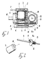
- figure 1 is a partial sectional front elevation view of a first embodiment of a pump according to the invention, taken along a plane which passes through the motor axis and the centerline of the reducer;
- figure 2 is a perspective detail view illustrating the coupling between the rotor of the motor and its shaft of the pump shown in figure 1;
- figure 3 is a sectional plan view of the pump shown in figure 1;
- figure 4 is a sectional view of the pump shown in figure 1 in the region of the piston and of the valves;
- figure 5 is a partial sectional plan view of a second embodiment of a pump according to the invention, taken along a longitudinal plane;
- figure 6 is a sectional elevation view of the pump shown in figure 5, taken along a plane which passes through the axis of the piston;
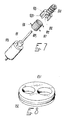
- figure 7 is a perspective detail view of the coupling between the rotor and the reducer of the pump shown in figure 5;
- figure 8 is a perspective view of a sealing gasket which is applied on the valve means of the pump shown in figure 5;
- figure 9 is a sectional view of a possible further embodiment of the valve means of the pump shown in figure 5;
- figures 10 and 11 are respectively a perspective view and a sectional elevation view of the sealing gasket comprised within the valve means of figure 9;
- figure 12 is a partially sectional plan view of a third model of pump;
- figure 13 is a perspective view of an intake and discharge value comprised within the pump shown in figure 12.
- With reference to figures 1 to 4, the first embodiment of the fluid metering pump, according to the invention, comprises a
body 1, advantageously made of plastic material, which internally defines afirst chamber 2, in which thestator pack 3 of a permanent-magnet synchronous motor is embedded in epoxy resin, and a secondcylindrical chamber 4, which is separate from said first chamber and in which therotor 5 of said motor is accommodated. - Two Faston
connectors 7 for connection to the electric mains extend out of the resin-embedded region from saidstator pack 3, which is approximately provided withelectric windings 6. - Said
second chamber 4 has an open end and an end provided with anaxial seat 8 for the insertion of a corresponding end of ametallic shaft 9 which supports saidrotor 5 so that it is free to rotate about its longitudinal axis. - Said
rotor 5 has, at the region of the open end of saidsecond chamber 4, a substantiallyradial tab 10 which is suitable for rotationally entraining a correspondingcylindrical tab 11 which is annularly embraced by a shock-absorbingrubber element 11a and extends eccentrically from a disk-like element 12 which is advantageously axially monolithic with aworm screw 13 which is advantageously made of plastic material and is rigidly associated with theshaft 9, the second end whereof is inserted in aseat 14 which is defined inside a housing orcasing 15, also advantageously made of plastic material, which is fixed to thebody 1 with screws which are not illustrated in the figures. - Said
shaft 9 is appropriately free to rotate in itsend seats - Two
parallel walls 16 and 17 extend inside saidhousing 15, and agearwheel 18 is rotationally coupled therebetween and meshes with saidworm screw 13. - Said
gearwheel 18 is advantageously monolithic with itsown rotation pivots eccentric tab 21 with anarticulation pivot 22 for the end of a connectingrod 23 the opposite end whereof is advantageously monolithic with apivot 24 which is rotatably coupled between the walls of apiston 25 which is also made of plastic material and is slidable in ahollow body 26 which is advantageously monolithic with saidbody 1, in which it defines a variable-volume chamber 27. - Said
piston 25, which conveniently has a cylindrical extension, is provided, on its outer surface, with an annular groove in which a sealing O-ring 28 is accommodated. - Said
hollow body 26 widens at the top of saidchamber 27 and forms an insertion seat for anintermediate element 29 and acover 30 which is externally associated with an O-ring 31 which is suitable for ensuring the seal on saidhollow body 26. - Said
cover 30 is advantageously associated with thebody 26 by means of snap-together couplings 32. - The
intermediate element 29 and thecover 30 are longitudinally traversed byducts 33 and 34 for the passage of fluid, and corresponding seats for intake and discharge valves, respectively 35 and 36, are defined therein. - Each of said
valves - Said cover is completed by two
connections - As regards the operation of the first embodiment of the metering pump according to the invention, the rotation of the permanent-magnet motor, the assumed direction of rotation whereof is irrelevant, causes the rotation of the
shaft 9 which supports theworm screw 13 which meshes with thegearwheel 18. - The
worm screw 13 and thegearwheel 18 perform a considerable speed reduction and transmit the motion to the connectingrod 23 by means of thearticulation pivot 22. - The
articulation pivot 22 and the connectingrod 23 convert the rotary motion into the reciprocating motion of thepiston 25, the stroke whereof in the direction suitable for increasing the volume of thechamber 27 causes a compression of thespring 39 and the intake of liquid through the mushroom-shaped element 27, whereas a stroke in the direction suitable for reducing the volume of thechamber 27 causes the drawn fluid to press on the mushroom-shaped element 38 and on thespring 40, allowing the discharge of said fluid. - Since the permanent-magnet motor is a synchronous electric motor, its rotation rate is fixed and preset, for a constant mains frequency, by the number of polar expansions.
- Due to this reason, the amount of fluid drawn and discharged by the
piston 25 is constant in the course of time. - In order to perform a perfect dosage of a given amount of fluid, it is sufficient to keep the motor running for the time required by the piston to complete a number of intake and discharge cycles equal to the volume of fluid to be metered divided by the maximum volume of the
chamber 27. - By means of the pump according to the invention it is therefore possible to precisely meter, at the appropriate time and in the required amount, a fluid detergent to be introduced in a washing machine, a dishwasher or similar household appliance.
- With reference now to figures 5 to 11, a second embodiment of the fluid metering pump according to the invention comprises a
body 101 advantageously made of plastic material which is shaped so as to internally define afirst chamber 102 in which thestator pack 103 of a permanent-magnet synchronous electric motor is embedded in epoxy resin. - Said
body 101 again defines asecond chamber 104 which is separate from the first one 102, has a cylindrical extension and internally accommodates therotor 105 of said motor. - Said
stator pack 103 haselectric windings 106 from which two Fastonconnectors 107 for connection to the electric mains extend. - As can be seen in figures 5 to 11, said
second chamber 104 has an open end and an end which is provided with anaxial seat 108 for the insertion of a corresponding end of an advantageouslymetallic shaft 109 which supports saidrotor 105 so that it is free to rotate about its longitudinal axis. - Said
rotor 105 has, at the region of the open end of saidsecond chamber 104, a substantiallyradial tub 110 and an axial bush 111 which resets head-on on a correspondingaxial bush 112 which has the same diameter and extends axially from a bell-shaped element 113 which is advantageously axially monolithic with aworm screw 114 advantageously made of plastic material. - Said
worm screw 114 is freely associated with theshaft 109, the second end whereof is inserted in aseat 115 which is defined inside a housing 116, again advantageously made of plastic material, which is fixed to thebody 101. - Said
axial bushes 111 and 112 are externally embraced by a cylindrical helicalmetallic spring 117 the ends whereof extend in a radial direction; afirst end 118 is in lateral contact with saidtab 110 and a second end 119 is inserted in a slot orhole 120 which is present on said bell-shaped element 113. - Two
parallel walls body 101 and, by cooperating with similarparallel walls gearwheel 125 which meshes with saidworm screw 114. - Said
gearwheel 125 is advantageously monolithic with itsrotation pivots bearing 128 which is externally provided with annular raised portions 129 which block its axial sliding with respect to the supporting walls. - Said bearing 128 advantageously rests, with one of its annular raised
portions 130, in a respectiveannular seat 131 which is defined laterally on saidgearwheel 125. - The
second rotation pivot 127 has aneccentric tab 132 with anarticulation pivot 133 for the end of a connecting rod 134 the opposite end whereof is advantageously monolithic with apivot 135 which is rotationally coupled between the walls of apiston 136, again advantageously made of plastic material, which is slidable in ahollow body 137 which is advantageously monolithic withsaid body 101. - Said
piston 136, which conveniently has a cylindrical extension, defines a variable-volume chamber 138 inside thehollow body 137 and has, on its outer surface, an annular groove in which a sealing O-ring 139 is accommodated. - Said
hollow body 137 expands at the head of saidchamber 138 and forms aseat 140 for the insertion of the valve system of the pump. - Said valve system comprises a
first insert 141 in which two fluid passages of appropriate shape, respectively 142 and 143, are defined. - An
intermediate element 144 is furthermore inserted in saidseat 140 and acover 145 is associated within theseat 140 of thehollow body 137 for example by means of snap-together couplings 146. - The
intermediate element 144 and thecover 145 are longitudinally traversed byfluid passage ducts - According to the invention, a
gasket 151 is interposed between theintermediate element 144 and thecover 145 and is shaped so as to be in contact both with their surfaces and with the lateral surface of theseat 140, so as to prevent any internal recirculation of fluid as well as any outward escape thereof. - As can be seen in figure 8, for this purpose said
gasket 151 is appropriately shaped like a figure-eight and has a small circumferential raisedportion 152 to be accommodated in a complementarily shaped annular recess of saidseat 140. - The compression performed by the
cover 145 upon closure also causes the outward expansion of thegasket 151 and of its raisedportion 152, producing a seal. - Each of said
valves 149 and 150, which are appropriately arranged in opposite positions, is constituted by a mushroom-shaped element, respectively 153 and 154, with a conical head accommodated in a complementarily shaped seat, and by a cylindrical helical spring, respectively 155 and 156, which is suitable for biasing the head against the corresponding seat. - Said
cover 145 is completed by twoconnections - As shown in figures 9-11, the valve system of the pump, according to the invention, can be constituted by two internally hollow elements, respectively an
intermediate element 244 and acover 245, which are again accommodated in an adapted seat at the head of the variable-volume chamber 138 and are longitudinally traversed byfluid passage ducts -
Said elements valves sealing element 252 substantially in the shape of a figure-eight which is interposed between theintermediate element 244 and thecover 245. - Sealing
seats valves spokes - Said
cover 245 is completed by twoconnections - As regards the effects and operation of the second embodiment of the pump with respect to the first one, according to the invention, said
spring 117, regardless of the angular position of thetab 110 when therotor 105 starts, by making contact with said tab exerts a thrust which causes its loading and therefore an elastic thrust in the opposite direction which is sufficient to give the motor such a torque as to move theworm screw 114 and therefore the entire pump. - The presence of the
bearing 128 further facilitates the rotation of thegearwheel 125 and reduces losses due to friction thereof. - With reference now to figures 12 and 13, a third embodiment of the fluid metering pump according to the invention is generally indicated by the
reference numeral 301 and comprises apiston 302 to which apivot 303 is articulated; said pivot is arranged at the end of a connectingrod 304 of a connecting rod-crank kinematic system which actuates it. - Said connecting rod-crank kinematic system, generally indicated by the
reference numeral 305, is in turn associated with a gearmotor unit similar to the previous one which is not illustrated and has a permanent-magnet synchronous motor. -
Said piston 302, which conveniently has a cylindrical extension, is slidable in ahollow body 306 in which it defines a variable-volume chamber 307, and has, on its outer surface, an annular groove in which asealing ring 308, for example an O-ring, is accommodated. - A
head 310 is fixed on saidhollow body 306, for example by means of screws, with the interposition of asealing ring 309, and supports avalve 311 which has both an intake function and a discharge function. - In particular, said
valve 311, which is conveniently made of rubber or of an equivalent material, has an umbrella-like shape and has atubular body 312 which is inserted in a complementarily shapedaxial seat 313 of thehead 310 and is connected to the outside by means of an alsoaxial connection 314. - Said
tubular body 312 is fixed to theseat 313 due to the insertion of a complementarily shaped raisedportion 316 which extends from theseat 313 in anannular recess 315 with which said tubular body is provided. - Advantageously, said
tubular body 312 has a beak-shapednozzle 317 which extends toward theconnection 314 and has elastically deformable sealing lips which define or close a rectilinear passage slit. - The perimetric lip of the
hood 318 of saidvalve 311 is elastically deformable and rests on aplanar surface 319 which is deformed on thehead 310 at the outlet of theseat 313. - Said
seat 313 is surrounded by anannular chamber 320 which is connected to the outside by means of aconnection 321 and to the inside by means of anannular chamber 322 which is formed between thehood 318 and thesurface 319. - In practice, the operation of the third embodiment of the pump according to the invention is as follows: the reciprocating motion of the
piston 302 alternately causes a suction effect and a pumping effect; the first effect causes the closing deformation of the lips of thehood 318 which causes the fluid to enter through theconnection 321, whereas the second effect causes the opening deformation of the lips of thenozzle 317, which cause the fluid drawn into thechamber 307 to escape through the slit defined thereby and through theconnection 314. - A single valve therefore performs the dual function of intake valve and discharge valve.
- It has thus in practice been observed that the invention has achieved the intended aim and objects.
- The pump, according to the invention, is in fact extremely compact and is advantageously mostly made of elements manufactured by injection-molding thermoplastic materials.
- The assembly of the various elements is performed with conventional production facilities.
- The invention thus conceived is susceptible to numerous modifications and variations, all of which are within the scope of the invention concept.
- All the details may furthermore be replaced with other technically equivalent elements.
- In practice, the materials employed, as well as the dimensions, may be any according to the requirements.
- Where technical features mentioned in any claims are followed by reference signs, those reference signs have been included for the sole purpose of increasing the intelligibility of the claims and accordingly such reference signs do not have any limiting effect on the scope of each element identified by way of example by such reference signs.
Claims (25)
1. Fluid metering pump, characterized in that it comprises a synchronous electric motor (3,5,6,7; 103,105,106,107) which is suitable for transmitting the rotary motion to speed reduction means (13,18;114,125) which are associated, by virtue of means (21-24; 132-135;303-305) suitable for converting rotary motion into reciprocating motion, with a piston element (25;136;302) which is slidable in a hollow body (26;137;306) in which it defines a variable-volume chamber (27;138;307) which is associated with valve means (35,36;149,150;311) for the intake and discharge of fluid.
2. Metering pump according to claim 1, characterized in that said synchronous electric motor is of the type with permanent magnets, the stator pack (3;103) whereof is embedded in resin in a first chamber (2;102) of the body (1;101) of said pump, the rotor (5;105) being accommodated in a second chamber (4;104) of said body which has an open end.
3. Metering pump according to one or more of the preceding claims, characterized in that said speed reduction means are constituted by a worm screw (13;114) which is associated with a gearwheel (18;125) which meshes therewith.
4. Metering pump according to one or more of the preceding claims, characterized in that said worm screw (13) is rigidly associated with a shaft (9) which freely supports said rotor (5) of said motor, said shaft (9) furthermore having its ends freely inserted in respective seats (8,14), a first one (8) of said seats extending axially from said second chamber (4) of said body (1), a second one (14) extending inside a housing (15) which is fixed to said body (1).
5. Metering pump according to one or more of the preceding claims, characterized in that said worm screw (13) is monolithic with a disk-like element (12) from which a tab (11) extends eccentrically, said tab being encompassed by a shock-absorbing rubber element (11a) and being rotationally entrained by a substantially radial tab (10) which extends from said rotor (5) at the open region of said second chamber (4).
6. Metering pump according to one or more of the preceding claims, characterized in that said gearwheel (18;125) has two axial rotation pivots (19,20;126,127) which are rotatably associated with walls (16,17;121-124) which extend inside said housing (15;116).
7. Metering pump according to one or more of the preceding claims, characterized in that said means suitable for converting the rotary motion into reciprocating motion are constituted by an eccentric tab (21;132) which extends from one (19;126) of said pivots of said gearwheel (18,125) and by a connecting rod (23;134;304) which is rotatably associated, with one end, with an articulation pivot (22;133) which is monolithic with said eccentric tab (21;132).
8. Metering pump according to one or more of the preceding claims, characterized in that said piston element is constituted by a piston (25;136;302) with cylindrical extension to which an end of said connecting rod (23;134;304) is articulated, said piston having, on its curved outer surface, a seat for a sealing ring (28;139;308) for example of the O-ring type.
9. Metering pump according to one or more of the preceding claims, characterized in that said hollow body (26;137;306) is monolithic with said motor body (1;101) and is shaped complementarily to the outer curved surface of said piston (25;136;302), said hollow body (26;137;306) having, at the head of said variable-volume chamber (27;138;307), an expansion in which an intermediate closure element (29;144;244) of said head and a cover (30;145;245) which is externally provided with a hydraulic sealing ring (31;151;252) are inserted, said cover being associated with said hollow body with snap-together couplings.
10. Metering pump according to one or more of the preceding claims, characterized in that said intermediate element (29;144;244) and said cover (30;145;245) are longitudinally traversed by fluid intake (34;147;247) and discharge (33;148;256) ducts which can be connected to a hydraulic circuit by means of connections (41,42;157,158; 255,256).
11. Metering pump according to one or more of the preceding claims, characterized in that said valve means for the intake and discharge of fluid are constituted by mushroom valves (35,36;153,154) which are arranged in opposite directions in seats which are defined in said intake (34;147) and discharge (33;148) ducts which are present in said intermediate element (29;144) and in said cover (30;145).
12. Fluid metering pump according to one or more of the preceding claims, characterized in that each mushroom valve is constituted by a mushroom-shaped element (35,36;153,154) with a substantially conical head which is pushed in a complementarily shaped seat by an axial cylindrical helical spring (39,40;155,156), said mushroom-shaped element and said springs being accommodated in an enlarged portion of each of said intake (34;147) and discharge (33;148) ducts.
13. Metering pump according to one or more of the preceding claims, characterized in that the coupling between the rotor (105) of said motor and the reducer (14;125) is provided by means of elastic spring means (117), the gearwheel (125) of said reducer being axially associated with a plain bearing (128) which is accommodated in a corresponding support of the pump body, said valve means (311) being enclosed between two hollow elements which are accommodated in a seat (313) of said head (310) and being associated with a single sealing element (309) which is suitable for preventing the internal recirculation and escape of liquid.
14. Metering pump according to one or more of the preceding claims, characterized in that said elastic spring means are constituted by a cylindrical helical spring (117) which embraces two bushes (111,112) of equal diameter which extend axially respectively from said rotor (105) and from the worm screw (114) of said speed reducer, both of which are associated with a supporting shaft (109).
15. metering pump according to one or more of the preceding claims, characterized in that the ends (118,119) of said spring extend radially and one (118) of said ends rests laterally on a tab (110) which extends eccentrically from said rotor (105), the other one (119) of said ends being inserted in a respective slot (120) or hole of a bell-shaped element (113) which extends axially from said worm screw (114).
16. Metering pump according to one or more of the preceding claims, characterized in that said plain bearing is constituted by a bearing (128) in which one (126) of the ends pivots of said gearwheel (125) is inserted, said bearing (128) having annular raised portions (129) which prevent its axial sliding with respect to its support (121,123) and having a further axial raised portion (130) which is in contact with an annular seat (131) which is defined laterally on said gearwheel (125).
17. Metering pump according to one or more of the preceding claims, characterized in that said sealing element suitable for preventing internal recirculation and escape of fluid is constituted by a gasket (151) which is substantially shaped like a figure-eight surrounds the seats of said valves (149,150), is interposed between said two hollow elements (144,145) and is in external contact with said seat (140) in which they are accommodated, said gasket having an outer circumferential raised portion (152) which is suitable for accommodating in a complementarily shaped recess of said seat (140).
18. Metering pump according to one or more of the preceding claims, characterized in that said single sealing element which is suitable for preventing internal recirculation and escape of fluid is constituted by a gasket (252) which is made of rubber or similar material and is substantially shaped like a figure-eight from which spokes (250,251) extend inward for connection to valves (248,249) which are monolithic therewith, said gasket (252) being interposed between said hollow elements (244,245) which enclose said valves and being in external contact with said seat in which they are accommodated.
19. Metering pump according to one or more of the preceding claims, characterized in that said valves (248,249), which are monolithic with said gasket (252) by means of said spokes (250,251), are constituted by shutter elements which conveniently have regions of their outer surface which are shaped complementarily to the respective seats to be closed, with which they are normally in contact.
20. Metering pump according to one or more of the preceding claims, characterized in that it comprises, on the head of said variable-volume chamber (307), an insert which is crossed by two shaped passages (314,321), respectively for the intake and discharge of fluid.
21. Metering pump according to one or more of the preceding claims, characterized in that said valve means are constituted by an umbrella-shaped valve (311) made of rubber or equivalent material, with an elastically deformable hood (318) and a tubular body (312) which is provided with a beak-shaped nozzle (317) with elastically deformable sealing lips, said valve being fixed with its body on the head (310) of said hollow body.
22. Metering pump according to one or more of the preceding claims, characterized in that said valve (311) is inserted with its tubular body (312) in a seat (320) of the head (310) of said hollow body, said seat being connected to the outside by means of a connection, said tubular body having an annular recess (215) in which a complementarily shaped raised portion (316), defined on the corresponding seat (320), is accommodated.
23. Metering pump according to one or more of the preceding claims, characterized in that said nozzle (317) of said tubular body (312) of said umbrella-shaped valve (311) extends on the side of said connection (314), its sealing lips defining a rectilinear slit.
24. Metering pump according to one or more of the preceding claims, characterized in that the hood (318) of said umbrella-shaped valve (311) rests with its elastically deformable perimetric lips (318) on a surface (319) of said head (310) on which said seat (320) for its tubular body (312) ends, a duct (321) for connection to the outside leading onto said surface inside the perimeter of said hood.
25. Metering pump according to one or more of the preceding claims, characterized in said head (310) for the umbrella-shaped valve (311) is fixed on said hollow body (306) in which said piston element (302) is slidable by means of screws, couplings or equivalent devices with the interposition of a hydraulic sealing ring (309).
Applications Claiming Priority (4)
| Application Number | Priority Date | Filing Date | Title |
|---|---|---|---|
| IT4174889 | 1989-11-17 | ||
| IT04174889A IT1236619B (en) | 1989-11-17 | 1989-11-17 | Detergent liq. metering pump driven by synchronous motor |
| IT4160090 | 1990-05-14 | ||
| IT41600A IT1238937B (en) | 1990-05-14 | 1990-05-14 | Detergent liq. metering pump driven by synchronous motor |
Publications (1)
| Publication Number | Publication Date |
|---|---|
| EP0433649A1 true EP0433649A1 (en) | 1991-06-26 |
Family
ID=26329134
Family Applications (1)
| Application Number | Title | Priority Date | Filing Date |
|---|---|---|---|
| EP19900121666 Withdrawn EP0433649A1 (en) | 1989-11-17 | 1990-11-13 | Fluid metering pump |
Country Status (2)
| Country | Link |
|---|---|
| US (1) | US5088902A (en) |
| EP (1) | EP0433649A1 (en) |
Cited By (15)
| Publication number | Priority date | Publication date | Assignee | Title |
|---|---|---|---|---|
| DE9200243U1 (en) * | 1992-01-11 | 1992-03-12 | Wolter, Hans, 8941 Sontheim, De | |
| DE4424257A1 (en) * | 1994-07-09 | 1996-01-18 | Aweco Kunststofftech Geraete | High-power centrifugal pump with single-phase sync. motor drive for dish washing machines |
| WO2004029454A1 (en) * | 2002-09-26 | 2004-04-08 | Fluid Management Inc. | Metering pump and valve assembly for use in the same |
| WO2005015019A1 (en) * | 2003-07-17 | 2005-02-17 | Cooper Cameron Corporation | Pump device for the hydraulic actuation of a valve |
| US7934376B2 (en) | 2005-04-27 | 2011-05-03 | Cameron International Corporation | Hydraulic actuation assembly |
| CN103174619A (en) * | 2013-04-02 | 2013-06-26 | 合肥日上电器有限公司 | Reciprocating injection type metering pump |
| GB2497816A (en) * | 2011-12-22 | 2013-06-26 | Hsu Chih-Kao | Water pump driven by AC synchronous motor |
| US9074445B2 (en) | 2009-03-27 | 2015-07-07 | Onesubsea Ip Uk Limited | DC powered subsea inverter |
| EP2829650A4 (en) * | 2012-03-22 | 2015-12-09 | Wuxi Little Swan Co Ltd | Washing machine and detergent delivery pump assembly thereof |
| EP3026267A1 (en) * | 2014-11-25 | 2016-06-01 | HILTI Aktiengesellschaft | Pump, in particular for the metered dispensing of a fluid |
| EP3022441A4 (en) * | 2013-07-17 | 2017-04-12 | SharkNinja Operating LLC | Variable flow rate mechanical pump assembly |
| CN106762507A (en) * | 2016-12-20 | 2017-05-31 | 郑州航空工业管理学院 | The energy-saving diesel engine of when many operational modes is driven with multistage variable fuel feeding |
| US10018009B2 (en) | 2015-02-26 | 2018-07-10 | Cameron International Corporation | Locking apparatus |
| IT201800009423A1 (en) * | 2018-10-12 | 2020-04-12 | Romaco Srl | DEVICE AND EQUIPMENT FOR THE DISPENSING OF DOSED QUANTITIES OF A LIQUID MATERIAL |
| CN114215714A (en) * | 2022-01-05 | 2022-03-22 | 多普医疗科技(郑州)有限公司 | Fluid conveying metering system and fluid conveying device |
Families Citing this family (17)
| Publication number | Priority date | Publication date | Assignee | Title |
|---|---|---|---|---|
| IT1246925B (en) * | 1991-04-04 | 1994-11-29 | Ricerca Elettromeccanica Srl | METHOD FOR THE PRODUCTION OF PARTS OF ELECTRIC MOTORS AND MOTORS USING PARTS PRODUCED WITH THAT METHOD |
| IT1259848B (en) * | 1992-11-27 | 1996-03-28 | Hydor Srl | SYNCHRONOUS ELECTRIC MOTOR, PARTICULARLY FOR IMMERSIBLE PUMPS AND INCORPORATING PUMP SUCH MOTOR |
| US5600953A (en) * | 1994-09-28 | 1997-02-11 | Aisin Seiki Kabushiki Kaisha | Compressed air control apparatus |
| US6135719A (en) * | 1997-12-29 | 2000-10-24 | Oilquip, Inc. | Method and apparatus for metering injection pump flow |
| US6135724A (en) * | 1998-07-08 | 2000-10-24 | Oilquip, Inc. | Method and apparatus for metering multiple injection pump flow |
| DE19860573A1 (en) * | 1998-12-29 | 2000-07-06 | Eberspaecher J Gmbh & Co | Fuel metering pump for a heater, in particular for an auxiliary heater or auxiliary heater of a motor vehicle |
| AU760775B2 (en) * | 1999-06-15 | 2003-05-22 | Lg Electronics Inc. | Method for controlling drain motor |
| AU749296B2 (en) | 1999-06-15 | 2002-06-20 | Lg Electronics Inc. | Device and method for controlling drain motor |
| US7011469B2 (en) * | 2001-02-07 | 2006-03-14 | R. Sanderson Management, Inc. | Piston joint |
| US7140343B2 (en) * | 2002-05-28 | 2006-11-28 | R. Sanderson Management, Inc. | Overload protection mechanism |
| BRPI0511592A (en) * | 2004-05-26 | 2008-01-02 | Sanderson R Man Inc | variable stroke and clearance mechanism |
| CN100385125C (en) * | 2005-01-10 | 2008-04-30 | 胡世璇 | High accuracy hydraulic synchronous proportional diverting current collector |
| TWI438342B (en) * | 2006-07-28 | 2014-05-21 | Lot Vacuum Co Ltd | Complex dry vacuum pump having root and screw rotors |
| US7708031B2 (en) * | 2006-11-13 | 2010-05-04 | International Business Machines Corporation | Check valve |
| US7942652B1 (en) * | 2008-11-29 | 2011-05-17 | Murray Lawrence D | Bi-directional centripetally-powered reciprocating pump |
| KR20120004208A (en) * | 2010-07-06 | 2012-01-12 | 삼성전자주식회사 | Detergent feeding apparatus and washing machine having the same |
| DE102014002955A1 (en) * | 2013-03-19 | 2014-09-25 | Marquardt Mechatronik Gmbh | metering |
Citations (7)
| Publication number | Priority date | Publication date | Assignee | Title |
|---|---|---|---|---|
| US1907110A (en) * | 1930-12-20 | 1933-05-02 | Hobart Bros Company | Car washing pump |
| US3855129A (en) * | 1972-03-06 | 1974-12-17 | Waters Associates Inc | Novel pumping apparatus |
| US4108167A (en) * | 1977-01-31 | 1978-08-22 | Teledyne Industries, Inc. | Dental syringe |
| GB2024528A (en) * | 1978-06-02 | 1980-01-09 | Askoll Srl | Centrifugal pump for small throughputs particularly for water circulation in aquariums and the like |
| EP0207430A2 (en) * | 1985-07-01 | 1987-01-07 | EASTHORPE INVESTMENTS Ltd. | Centrifugal pump |
| EP0223643A1 (en) * | 1985-10-04 | 1987-05-27 | DOSAPRO MILTON ROY, SociÀ©té dite: | Process to define exactly the flow rate of a dosing pump, and such a pump |
| DE3630088A1 (en) * | 1986-09-04 | 1988-03-17 | Bosch Gmbh Robert | Actuating device |
Family Cites Families (10)
| Publication number | Priority date | Publication date | Assignee | Title |
|---|---|---|---|---|
| FR588113A (en) * | 1924-08-29 | 1925-04-30 | Compact, direct drive compressor | |
| US2260180A (en) * | 1937-07-19 | 1941-10-21 | John H Herder | Constant pressure diaphragm pump |
| US3131646A (en) * | 1962-10-15 | 1964-05-05 | Parco Products Co | Hand pump |
| US3416557A (en) * | 1964-04-29 | 1968-12-17 | Union Tank Car Co | Check valve with wiping action |
| US3664774A (en) * | 1970-05-05 | 1972-05-23 | Dexter Automatic Products Co I | Primer pump |
| US3730217A (en) * | 1971-05-19 | 1973-05-01 | Gen Motors Corp | Check valve |
| US4422831A (en) * | 1981-11-02 | 1983-12-27 | Bender Machine Works, Inc. | Pump |
| US4614479A (en) * | 1984-04-19 | 1986-09-30 | Jackson Liu | Adjustable automatically controlled pneumatic pump device |
| FR2581707B1 (en) * | 1985-05-10 | 1987-06-26 | Tecnoma | IMPROVEMENT ON MEMBRANE PUMPS |
| GB8624620D0 (en) * | 1986-10-14 | 1986-11-19 | Scholl Inc | Fluid dispenser |
-
1990
- 1990-11-13 EP EP19900121666 patent/EP0433649A1/en not_active Withdrawn
- 1990-11-14 US US07/612,378 patent/US5088902A/en not_active Expired - Lifetime
Patent Citations (8)
| Publication number | Priority date | Publication date | Assignee | Title |
|---|---|---|---|---|
| US1907110A (en) * | 1930-12-20 | 1933-05-02 | Hobart Bros Company | Car washing pump |
| US3855129A (en) * | 1972-03-06 | 1974-12-17 | Waters Associates Inc | Novel pumping apparatus |
| US3855129B1 (en) * | 1972-03-06 | 1985-10-08 | ||
| US4108167A (en) * | 1977-01-31 | 1978-08-22 | Teledyne Industries, Inc. | Dental syringe |
| GB2024528A (en) * | 1978-06-02 | 1980-01-09 | Askoll Srl | Centrifugal pump for small throughputs particularly for water circulation in aquariums and the like |
| EP0207430A2 (en) * | 1985-07-01 | 1987-01-07 | EASTHORPE INVESTMENTS Ltd. | Centrifugal pump |
| EP0223643A1 (en) * | 1985-10-04 | 1987-05-27 | DOSAPRO MILTON ROY, SociÀ©té dite: | Process to define exactly the flow rate of a dosing pump, and such a pump |
| DE3630088A1 (en) * | 1986-09-04 | 1988-03-17 | Bosch Gmbh Robert | Actuating device |
Cited By (24)
| Publication number | Priority date | Publication date | Assignee | Title |
|---|---|---|---|---|
| DE9200243U1 (en) * | 1992-01-11 | 1992-03-12 | Wolter, Hans, 8941 Sontheim, De | |
| DE4424257A1 (en) * | 1994-07-09 | 1996-01-18 | Aweco Kunststofftech Geraete | High-power centrifugal pump with single-phase sync. motor drive for dish washing machines |
| DE4424257C2 (en) * | 1994-07-09 | 1999-03-18 | Aweco Kunststofftech Geraete | High performance centrifugal pump with single phase synchronous motor drive |
| WO2004029454A1 (en) * | 2002-09-26 | 2004-04-08 | Fluid Management Inc. | Metering pump and valve assembly for use in the same |
| WO2005015019A1 (en) * | 2003-07-17 | 2005-02-17 | Cooper Cameron Corporation | Pump device for the hydraulic actuation of a valve |
| GB2419645A (en) * | 2003-07-17 | 2006-05-03 | Cooper Cameron Corp | Pump device for the hydraulic actuation of a valve |
| GB2419645B (en) * | 2003-07-17 | 2008-07-02 | Cooper Cameron Corp | Pump device for the hydraulic actuation of a valve |
| US8770950B2 (en) | 2003-07-17 | 2014-07-08 | Cameron International Corporation | Pump device for the hydraulic actuation of a valve |
| US7934376B2 (en) | 2005-04-27 | 2011-05-03 | Cameron International Corporation | Hydraulic actuation assembly |
| US9074445B2 (en) | 2009-03-27 | 2015-07-07 | Onesubsea Ip Uk Limited | DC powered subsea inverter |
| GB2497816A (en) * | 2011-12-22 | 2013-06-26 | Hsu Chih-Kao | Water pump driven by AC synchronous motor |
| EP2829650A4 (en) * | 2012-03-22 | 2015-12-09 | Wuxi Little Swan Co Ltd | Washing machine and detergent delivery pump assembly thereof |
| EP2829649A4 (en) * | 2012-03-22 | 2016-02-17 | Wuxi Little Swan Co Ltd | Dosing device overcoming changes in viscidity of detergent and method for controlling same |
| CN103174619A (en) * | 2013-04-02 | 2013-06-26 | 合肥日上电器有限公司 | Reciprocating injection type metering pump |
| EP3022441A4 (en) * | 2013-07-17 | 2017-04-12 | SharkNinja Operating LLC | Variable flow rate mechanical pump assembly |
| US10932644B2 (en) | 2013-07-17 | 2021-03-02 | Sharkninja Operating Llc | Variable flow rate mechanical pump assembly |
| US11401928B2 (en) | 2013-07-17 | 2022-08-02 | Sharkninja Operating Llc | Variable flow rate mechanical pump assembly |
| EP3026267A1 (en) * | 2014-11-25 | 2016-06-01 | HILTI Aktiengesellschaft | Pump, in particular for the metered dispensing of a fluid |
| US10018009B2 (en) | 2015-02-26 | 2018-07-10 | Cameron International Corporation | Locking apparatus |
| CN106762507A (en) * | 2016-12-20 | 2017-05-31 | 郑州航空工业管理学院 | The energy-saving diesel engine of when many operational modes is driven with multistage variable fuel feeding |
| CN106762507B (en) * | 2016-12-20 | 2018-07-10 | 郑州航空工业管理学院 | The energy-saving diesel engine of when more operational modes is driven with multistage variable fuel feeding |
| IT201800009423A1 (en) * | 2018-10-12 | 2020-04-12 | Romaco Srl | DEVICE AND EQUIPMENT FOR THE DISPENSING OF DOSED QUANTITIES OF A LIQUID MATERIAL |
| CN114215714A (en) * | 2022-01-05 | 2022-03-22 | 多普医疗科技(郑州)有限公司 | Fluid conveying metering system and fluid conveying device |
| CN114215714B (en) * | 2022-01-05 | 2024-05-03 | 多普医疗科技(郑州)有限公司 | Fluid conveying metering system and fluid conveying device |
Also Published As
| Publication number | Publication date |
|---|---|
| US5088902A (en) | 1992-02-18 |
Similar Documents
| Publication | Publication Date | Title |
|---|---|---|
| US5088902A (en) | Piston type metering pump | |
| US8926275B2 (en) | Centrifugal pump | |
| AU2002325292B2 (en) | Dishwasher comprising spraying arms and a circulating pump | |
| US5668425A (en) | Startup device for the rotor of a permanent-magnet synchronous motor | |
| US7347005B2 (en) | Ventilation system for household appliances in particular for washing machines | |
| KR20070108530A (en) | Bi-directional air flow damper having uni-directional synchronous motor | |
| CN110145448B (en) | Small-size high-pressure plunger high-pressure water pump based on two-degree-of-freedom motor | |
| KR20220024987A (en) | cleaning appliance | |
| CN217696271U (en) | Arrange thick liquid valve and food preparation machine | |
| CA2939613C (en) | Machine for preparing liquid products, in particular via capsules | |
| CN209499949U (en) | Tooth flusher | |
| CN214258974U (en) | Water-passing temperature limiter assembly and liquid container | |
| KR20220046837A (en) | Automatic detergent input device of washing machine | |
| CN101925747B (en) | Household appliance for washing articles | |
| CN105515231A (en) | Integrated water pump | |
| CN217105356U (en) | Shower and cleaning agent adding assembly thereof | |
| JPH03284293A (en) | Automatic detergent dispenser | |
| CN106381632B (en) | Air pump for washing machine and washing machine with same | |
| KR100669230B1 (en) | Air mixing apparatus of hydraulic pump | |
| CN214273900U (en) | Micro fluid pump and pressure fluid application equipment | |
| CN218666780U (en) | Automatic put in subassembly and washing equipment | |
| KR200189636Y1 (en) | The center lose structure of vacuum pump | |
| CN216036176U (en) | Foam pump and radial cavity driving structure thereof | |
| CN217827790U (en) | Get rid of residual water structure | |
| CN213711289U (en) | Micro fluid pump |
Legal Events
| Date | Code | Title | Description |
|---|---|---|---|
| PUAI | Public reference made under article 153(3) epc to a published international application that has entered the european phase |
Free format text: ORIGINAL CODE: 0009012 |
|
| AK | Designated contracting states |
Kind code of ref document: A1 Designated state(s): AT BE CH DE DK ES FR GB GR IT LI LU NL SE |
|
| 17P | Request for examination filed |
Effective date: 19911004 |
|
| STAA | Information on the status of an ep patent application or granted ep patent |
Free format text: STATUS: THE APPLICATION IS DEEMED TO BE WITHDRAWN |
|
| 18D | Application deemed to be withdrawn |
Effective date: 19930602 |