EP0431901B1 - Document delivery and abort mechanism - Google Patents
Document delivery and abort mechanism Download PDFInfo
- Publication number
- EP0431901B1 EP0431901B1 EP90313166A EP90313166A EP0431901B1 EP 0431901 B1 EP0431901 B1 EP 0431901B1 EP 90313166 A EP90313166 A EP 90313166A EP 90313166 A EP90313166 A EP 90313166A EP 0431901 B1 EP0431901 B1 EP 0431901B1
- Authority
- EP
- European Patent Office
- Prior art keywords
- door
- accept
- power shaft
- abort
- accept door
- Prior art date
- Legal status (The legal status is an assumption and is not a legal conclusion. Google has not performed a legal analysis and makes no representation as to the accuracy of the status listed.)
- Expired - Lifetime
Links
- 230000007246 mechanism Effects 0.000 title claims abstract description 35
- 239000004035 construction material Substances 0.000 description 1
- 238000001514 detection method Methods 0.000 description 1
- 230000000284 resting effect Effects 0.000 description 1
- 230000011664 signaling Effects 0.000 description 1
Images


Classifications
-
- B—PERFORMING OPERATIONS; TRANSPORTING
- B65—CONVEYING; PACKING; STORING; HANDLING THIN OR FILAMENTARY MATERIAL
- B65H—HANDLING THIN OR FILAMENTARY MATERIAL, e.g. SHEETS, WEBS, CABLES
- B65H29/00—Delivering or advancing articles from machines; Advancing articles to or into piles
- B65H29/38—Delivering or advancing articles from machines; Advancing articles to or into piles by movable piling or advancing arms, frames, plates, or like members with which the articles are maintained in face contact
- B65H29/40—Members rotated about an axis perpendicular to direction of article movement, e.g. star-wheels formed by S-shaped members
-
- G—PHYSICS
- G07—CHECKING-DEVICES
- G07D—HANDLING OF COINS OR VALUABLE PAPERS, e.g. TESTING, SORTING BY DENOMINATIONS, COUNTING, DISPENSING, CHANGING OR DEPOSITING
- G07D11/00—Devices accepting coins; Devices accepting, dispensing, sorting or counting valuable papers
- G07D11/10—Mechanical details
- G07D11/14—Inlet or outlet ports
Definitions
- This invention relates to automatic document dispensing machines for dispensing documents such as paper money, as at a machine for returning the paper money portion of change from a vending machine.
- EP-A 0 034 502 discloses a door mechanism for an automatic document dispensing machine and the like comprising an accept door pivotally mounted in the automatic document dispensing machine for dispensing documents from the machine, a power shaft mounted in the automatic document dispensing machine which is adapted to be rotated in response to signals from the automatic document dispensing machine, and locking means operatively connected to the power shaft to be caused thereby to lock the accept door in a closed position when desired, in a locking position of the power shaft.
- the machine When the machine has successfully dispensed documents, it causes the power shaft to be rotated to operate the locking means to unlock the accept door which can then be opened by the user.
- a door mechanism of the type known from EP-A 0 034 502 is characterised by accept door opening means connected to the accept door and mounted on the power shaft for operation thereby for opening the accept door, the locking means preventing the accept door opening means from rotating the power shaft in the locking position of the power shaft.
- a document delivery and abort mechanism 11 for an automatic document dispensing machine 13 that comprises an accept door 15 that opens for dispensing documents from automatic document dispensing machine 13 after a stacker wheel 16 rotates and delivers to it documents such as paper money, a power shaft 17 that controls the opening of accept door 15, accept door opening means 19 mounted on the power shaft 17 and connected to the accept door 15 for opening accept door 15, and locking means 21 for locking the accept door 15 in a closed position by preventing rotation of the power shaft 17 in a direction that opens accept door 15.
- Dispensing machine 13 includes processing mechanism 20 (Fig. 8) and power supply mechanism 22.
- Accept door 15 is mounted in automatic document dispensing machine 13 on a pivot pin 23 and may be tilted outwardly from its closed position in Fig. 1 to the open position of Fig. 2 to dispense documents therefrom if the dispense is without error, that is, if the documents have been correctly processed in automatic document dispensing machine 13 and correctly delivered to accept door 15 for dispensing.
- Dispensing machine 13 is provided with an error detection mechanism that checks the accuracy of each dispense before the dispense is dispensed from machine 13.
- Power shaft 17 is mounted in automatic document dispensing machine 13 below accept door 15, and rotation of power shaft 17, in response to a signal from machine 13, drives the accept door opening means 19 to open the accept door 15.
- Accept door opening means 19 has an L-shaped attachment link 25 that is pivotally mounted at one end 28 to a pivot pin 27 mounted on accept door 15 and is pivotally attached at its other end 26 to drive link 29 at its end 31 to pivot pin 33.
- the other end 34 of drive link 29 is connected to power drive or drive shaft 17 and is rotated by shaft 17 to rotate link 25 to open door 15.
- accept door opening means 19 includes a crank pin 35 radially mounted on power shaft 17 that fits into a slot 37 in end 34 of door drive link 29.
- Slot 37 is in the form of a 180 degree annular groove around circumference of power shaft 17 which allows crank pin 35 to rotate freely between bases 37a and 37b of slot 37.
- slot 37 is about 0,24cm (0.093 inches) wide
- crank pin 35 is about 0,20cm (0.078 inches) in diameter so as to provide working clearance between crank pin 35 and the side walls of slot 37.
- the accept door 15 is closed, and the position of crank pin 35 on power shaft 17 is at about 3 o'clock near base 37b (Fig. 7) of slot 37.
- crank pin 35 rotates to about 6 o'clock rotating drive link 29 with it, which pushes attachment link 25 to open accept door 15.
- a spring 61 is mounted around power shaft 17, and has a first end portion 63 attached to accept door drive link 29 and a second end portion 65 attached to the frame 66 of dispensing machine 13.
- the spring force of spring 61 urges drive link 29 counterclockwise placing end 31 of drive link 29 over center, that is, placing a center line between pivot 27 at accept door 15 and pivot pin 33 to the right of power shaft 17.
- An abort door 43 (Figs. 1-3) is also pivotally mounted in the automatic document dispensing machine 13 on pivot pin 23 near accept door 15. Documents may be dropped into a lockable drawer, compartment or escrow bin 45 (Figs. 1-3) when abort door 43 is open if there is error in the processing of the documents in the automatic document dispensing machine 13. Abort door 43 is shown closed in Fig. 1 and open in Fig. 3.
- Abort door opening means 47 (Figs. 1-3) connects power shaft 17 to the abort door 43 so that rotation of power shaft 17 opens abort door 43 and permits it to close in response to signals from the mechanism 13.
- Abort door opening means 47 has an abort door attachment link 49 wit one end 50 connected to abort door 43 at pivot pin 51 and its other end 52 pivotally connected to link 53 at pivot pin 55.
- the abort door link 53 is pivotally connected at one end 54 to end 52 of link 49 and at its other end 56 to power shaft 17.
- the abort door opening means 47 includes a crank pin 57 radially mounted on power shaft 17 which fits into a slot 59 formed in abort door drive link 53.
- Crank pin 57 rotates counterclockwise, arrow 60, to open abort door 43, and crank pin 57 is rotated clockwise to allow spring 69 to close abort door 43.
- slot 59 form half of an annular ring around power shaft 17 for 180 degree rotation of shaft 17 without interference by crank pin 57.
- crank pin 57 on power shaft 17 is at about 12 o'clock near base 59a (Fig. 6) of slot 59.
- crank pin 57 rotates to about 9 o'clock rotating drive link 53 with it, which pulls attachment link 49 downwardly to open abort door 43.
- the spring force of spring 61 opposes the opening of accept door 15, and does more than just balance the forces on accept door 15 in closed position, and spring 61 loads or urges the crank pin 35 of power shaft 17 against the base 37b of slot 37. This spring force pulls the accept door 15 closed when power shaft 17 returns to an accept door closed position as shown in Figs. 7, 1, and 4.
- Extension spring 69 (Figs. 1-3 and 8) may be attached at one end to abort door 43 and at the other end to accept door 15 to close abort door 43 at right angles to the accept door 15 as shown in Fig. 1.
- stacker wheel 16 (Fig. 1) rotates and delivers documents such as paper money onto abort door 43. If the documents have been correctly processed in the automatic document dispensing machine 13, power shaft 17 (Fig. 7) turns clockwise in the accept door opening direction so that crank pin 35, in contact with base 37b of slot 37, rotates drive link 29 clockwise to open the door 15. Power shaft 17 continues to rotate clockwise in door opening direction which rotates link 29 in a clockwise direction, causing attachment link 25 to rotate clockwise until accept door 15 opens by pivoting clockwise on pivot pin 23 to allow the customer to reach through the door 15 and pick up the money.
- accept door 15 When accept door 15 is open, it may be opened farther by pulling accept door 15 downwardly to exert more pressure against spring 61. When the customer removes his hand from pulling on door 15, spring 61 returns accept door 15 to its original open position. The spring action of spring 61 prevents damage occurring to power shaft 17 and the control mechanisms connected to shaft 17 when a customer opens accept door 15 wider than its original standard open position.
- crank pin 35 assumes its original position at 3 o'clock position in contact with base 37b of slot 37.
- Accept door 15 is closed, not by the rotation of power shaft 17, but by spring 61, which exerts its pressure against the link 29 to force end 31 of link 29 counterclockwise from 9 o'clock into its position at 6 o'clock (Fig. 1) to close the accept door 15.
- crank pin 35 is in contact with base 37b of slot 37 and crank pin 35 is positioned at 3 o'clock, and crank pin 57 is in contact with base 59a in slot 59 of abort door drive link 53 and crank pin 57 is positioned at 12 o'clock.
- crank pin 57 rotates clockwise with power shaft 17 and does not interfere with the clockwise rotation of abort door drive link 53 as it is being pulled upwardly by abort door attachment link 49 and abort door 43.
- a detecting mechanism 71 is mounted near doors 15 and 43 on housing 73 for detecting and signaling when doors 15 and 43 are closed, and detecting mechanism 71 includes a photocell 75 and a microswitch 77.
- crank pins 35 and 57 are positioned so that accept door 15 and abort door 43 may be opened and closed without power shaft 17 rotating more tan 180 degrees.
- accept door 15 When accept door 15 is in its standard open position, it may be opened even farther by pulling on the accept door without causing damage to the power shaft 17 or its control mechanisms.
Landscapes
- Engineering & Computer Science (AREA)
- Mechanical Engineering (AREA)
- Physics & Mathematics (AREA)
- General Physics & Mathematics (AREA)
- Control Of Vending Devices And Auxiliary Devices For Vending Devices (AREA)
- Pile Receivers (AREA)
- Collation Of Sheets And Webs (AREA)
- Steering Control In Accordance With Driving Conditions (AREA)
- Diaphragms For Electromechanical Transducers (AREA)
- Lock And Its Accessories (AREA)
- Memory System Of A Hierarchy Structure (AREA)
- Warehouses Or Storage Devices (AREA)
Abstract
Description
- This invention relates to automatic document dispensing machines for dispensing documents such as paper money, as at a machine for returning the paper money portion of change from a vending machine.
- EP-A 0 034 502 discloses a door mechanism for an automatic document dispensing machine and the like comprising
an accept door pivotally mounted in the automatic document dispensing machine for dispensing documents from the machine,
a power shaft mounted in the automatic document dispensing machine which is adapted to be rotated in response to signals from the automatic document dispensing machine,
and locking means operatively connected to the power shaft to be caused thereby to lock the accept door in a closed position when desired, in a locking position of the power shaft. - When the machine has successfully dispensed documents, it causes the power shaft to be rotated to operate the locking means to unlock the accept door which can then be opened by the user.
- According to the invention, a door mechanism of the type known from EP-A 0 034 502 is characterised by accept door opening means connected to the accept door and mounted on the power shaft for operation thereby for opening the accept door, the locking means preventing the accept door opening means from rotating the power shaft in the locking position of the power shaft.
- With this arrangement, locking and unlocking of the door and opening and closing of the door can be carried out by appropriate rotation of the one power shaft.
-
- Fig. 1 is a side view in elevation of a document delivery and abort mechanism in an automatic document dispensing machine with its accept door in a closed position and its abort door in a closed position;
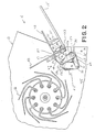
- Fig. 2 is a side view in elevation of the mechanism of Fig. 1 with its accept door in an open position;
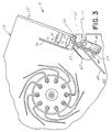
- Fig. 3 is a side view in elevation of the mechanism of Fig. 1 with the accept door closed and the abort door open;
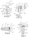
- Fig. 4 is a side view in elevation showing locking means for locking the accept door in closed position;
- Fig. 5 is a partial view in elevation of the mechanism of Fig. 1, and shows an accept door return spring and an accept door drive link connected to the power shaft;
- Fig. 6 is a view in section of the power shaft with an abort door drive link connected thereto;
- Fig. 7 is a view in section of the power shaft with an accept door drive link and accept door return spring connected thereto; and
- Fig. 8 is a front view in elevation of the document delivery and abort mechanism with its accept door in a closed position and its abort door in a closed position.
- Turning to the drawings, there is shown in Figs. 1-3 and 8 a document delivery and
abort mechanism 11 for an automaticdocument dispensing machine 13, that comprises anaccept door 15 that opens for dispensing documents from automaticdocument dispensing machine 13 after astacker wheel 16 rotates and delivers to it documents such as paper money, apower shaft 17 that controls the opening ofaccept door 15, acceptdoor opening means 19 mounted on thepower shaft 17 and connected to theaccept door 15 for openingaccept door 15, and locking means 21 for locking theaccept door 15 in a closed position by preventing rotation of thepower shaft 17 in a direction that opens acceptdoor 15. - Automatic
document dispensing machine 13 is shown and described in Technitrol U.S. Patent No. 4,691,910, issued September 8, 1987, which is incorporated herein by reference, and dispensingmachine 13 includes processing mechanism 20 (Fig. 8) andpower supply mechanism 22. - Accept
door 15 is mounted in automaticdocument dispensing machine 13 on apivot pin 23 and may be tilted outwardly from its closed position in Fig. 1 to the open position of Fig. 2 to dispense documents therefrom if the dispense is without error, that is, if the documents have been correctly processed in automaticdocument dispensing machine 13 and correctly delivered to acceptdoor 15 for dispensing.Dispensing machine 13 is provided with an error detection mechanism that checks the accuracy of each dispense before the dispense is dispensed frommachine 13. -
Power shaft 17 is mounted in automaticdocument dispensing machine 13 below acceptdoor 15, and rotation ofpower shaft 17, in response to a signal frommachine 13, drives the accept door opening means 19 to open theaccept door 15. - Accept door opening means 19 has an L-
shaped attachment link 25 that is pivotally mounted at oneend 28 to apivot pin 27 mounted onaccept door 15 and is pivotally attached at itsother end 26 to drivelink 29 at itsend 31 topivot pin 33. Theother end 34 ofdrive link 29 is connected to power drive or driveshaft 17 and is rotated byshaft 17 to rotatelink 25 to opendoor 15. - Referring to Figs. 5 and 7, accept
door opening means 19 includes acrank pin 35 radially mounted onpower shaft 17 that fits into aslot 37 inend 34 ofdoor drive link 29. -
Slot 37 is in the form of a 180 degree annular groove around circumference ofpower shaft 17 which allowscrank pin 35 to rotate freely betweenbases 37a and 37b ofslot 37. Preferably,slot 37 is about 0,24cm (0.093 inches) wide, andcrank pin 35 is about 0,20cm (0.078 inches) in diameter so as to provide working clearance betweencrank pin 35 and the side walls ofslot 37. As shown in Fig. 1, theaccept door 15 is closed, and the position ofcrank pin 35 onpower shaft 17 is at about 3 o'clock near base 37b (Fig. 7) ofslot 37. Aspower shaft 17 rotates clockwise to open accept door 15 (Fig. 2),crank pin 35 rotates to about 6 o'clock rotatingdrive link 29 with it, which pushesattachment link 25 to openaccept door 15. - To lock the
door 15 in closed position and prevent the door from being pulled open, theshaft 17 is locked in position bylinks spring 61 is mounted aroundpower shaft 17, and has afirst end portion 63 attached to acceptdoor drive link 29 and asecond end portion 65 attached to theframe 66 ofdispensing machine 13. The spring force ofspring 61 urges drivelink 29 counterclockwise placingend 31 ofdrive link 29 over center, that is, placing a center line betweenpivot 27 at acceptdoor 15 andpivot pin 33 to the right ofpower shaft 17. Referring to Fig. 4, when aforce 41 is applied to acceptdoor 15 in an attempt to pull open the closeddoor 15, the edge 26a ofend 26 ofdoor attachment link 25 which is attached betweendoor 15 andpivot pin 33 oflink 29, is pulled towards, and eventually into contact with (at area 25a of link 25),power shaft 17. As this happens, the upward movement of edge 26a ofend 26 oflink 25 pulled by theforce 41 ondoor 15 towardpower shaft 17 causesend 31 oflink 29 to move in the direction indicated byarrow 39 of Fig. 4, and this direction of movement holds thedoor 15 closed. The greater the pullingforce 41 ondoor 15 to force open the closeddoor 15, the greater therotational force 39 onend 31 oflink 29 in the direction that holdsaccept door 15 closed. - An abort door 43 (Figs. 1-3) is also pivotally mounted in the automatic
document dispensing machine 13 onpivot pin 23 near acceptdoor 15. Documents may be dropped into a lockable drawer, compartment or escrow bin 45 (Figs. 1-3) whenabort door 43 is open if there is error in the processing of the documents in the automaticdocument dispensing machine 13.Abort door 43 is shown closed in Fig. 1 and open in Fig. 3. - Abort door opening means 47 (Figs. 1-3) connects
power shaft 17 to theabort door 43 so that rotation ofpower shaft 17 opensabort door 43 and permits it to close in response to signals from themechanism 13. Abort door opening means 47 has an abortdoor attachment link 49 wit oneend 50 connected toabort door 43 atpivot pin 51 and itsother end 52 pivotally connected tolink 53 atpivot pin 55. Theabort door link 53 is pivotally connected at oneend 54 to end 52 oflink 49 and at itsother end 56 topower shaft 17. - Referring to Fig. 6, the abort door opening means 47 includes a
crank pin 57 radially mounted onpower shaft 17 which fits into aslot 59 formed in abortdoor drive link 53. Crankpin 57 rotates counterclockwise,arrow 60, to openabort door 43, andcrank pin 57 is rotated clockwise to allowspring 69 to closeabort door 43. - The sides of
slot 59 form half of an annular ring aroundpower shaft 17 for 180 degree rotation ofshaft 17 without interference bycrank pin 57. - In operation,
power shaft 17 is rotated counterclockwise by a signal frommachine 13, as shown byarrow 60 in Fig. 6, to swinglink 53 counterclockwise and pulllink 49 downwardly to openabort door 43. Fig. 1 shows abort door closed, and Fig. 3 shows abort door 43 open. As shown in Fig. 1, thecrank pin 57 onpower shaft 17 is at about 12 o'clock nearbase 59a (Fig. 6) ofslot 59. Aspower shaft 17 rotates counterclockwise to open abort door 43 (Fig. 3),crank pin 57 rotates to about 9 o'clock rotatingdrive link 53 with it, which pullsattachment link 49 downwardly to openabort door 43. - As shown in Fig. 5, the spring force of
spring 61 opposes the opening ofaccept door 15, and does more than just balance the forces on acceptdoor 15 in closed position, andspring 61 loads or urges thecrank pin 35 ofpower shaft 17 against the base 37b ofslot 37. This spring force pulls theaccept door 15 closed whenpower shaft 17 returns to an accept door closed position as shown in Figs. 7, 1, and 4. - Extension spring 69 (Figs. 1-3 and 8) may be attached at one end to abort
door 43 and at the other end to acceptdoor 15 to closeabort door 43 at right angles to theaccept door 15 as shown in Fig. 1. - In operation, stacker wheel 16 (Fig. 1) rotates and delivers documents such as paper money onto
abort door 43. If the documents have been correctly processed in the automaticdocument dispensing machine 13, power shaft 17 (Fig. 7) turns clockwise in the accept door opening direction so thatcrank pin 35, in contact with base 37b ofslot 37, rotatesdrive link 29 clockwise to open thedoor 15.Power shaft 17 continues to rotate clockwise in door opening direction which rotateslink 29 in a clockwise direction, causingattachment link 25 to rotate clockwise until acceptdoor 15 opens by pivoting clockwise onpivot pin 23 to allow the customer to reach through thedoor 15 and pick up the money. - When accept
door 15 is open, it may be opened farther by pulling acceptdoor 15 downwardly to exert more pressure againstspring 61. When the customer removes his hand from pulling ondoor 15,spring 61 returns acceptdoor 15 to its original open position. The spring action ofspring 61 prevents damage occurring topower shaft 17 and the control mechanisms connected toshaft 17 when a customer opens acceptdoor 15 wider than its original standard open position. - When the documents have been withdrawn by the customer,
power shaft 17 is rotated counterclockwise to close thedoor 15 in response to signals frommachine 13, andcrank pin 35 assumes its original position at 3 o'clock position in contact with base 37b ofslot 37. - Accept
door 15 is closed, not by the rotation ofpower shaft 17, but byspring 61, which exerts its pressure against thelink 29 to forceend 31 oflink 29 counterclockwise from 9 o'clock into its position at 6 o'clock (Fig. 1) to close theaccept door 15. - If the documents have been incorrectly processed, this is sensed by automatic
document dispensing machine 13 which signalspower shaft 17 which is rotated counterclockwise by the signal frommachine 13 so thatcrank pin 57, in contact withbase 59a ofslot 59, rotates abortdoor drive link 53 counterclockwise, which pulls abortdoor attachment link 49 and abortdoor 43 downwardly to open the abort door 40, as shown in Fig. 3, until the incorrect dispense resting onabort door 43 slides offabort doors 43 and drop into thedrawer 45. - After the aborted documents slide into the
drawer 45,power shaft 17 is rotated in an abort door closing direction, clockwise in Fig. 6, to returnabort door 43 to the currency accept position of Fig. 1. When abortdoor drive link 53 is disengaged frompower shaft 17, theextension spring 69 attached between acceptdoor 15 andabort door 43pulls abort door 43 back to its right angle position with respect to acceptdoor 15 as shown in Fig. 1. - When accept
door 15 is closed (Fig. 1) andabort door 17 is in its currency accepting position of Fig. 1,crank pin 35 is in contact with base 37b ofslot 37 andcrank pin 35 is positioned at 3 o'clock, andcrank pin 57 is in contact withbase 59a inslot 59 of abortdoor drive link 53 andcrank pin 57 is positioned at 12 o'clock. - When accept
door 15 is being opened,crank pin 57 rotates clockwise withpower shaft 17 and does not interfere with the clockwise rotation of abortdoor drive link 53 as it is being pulled upwardly by abortdoor attachment link 49 andabort door 43. - While
abort door 43 opens and closes, the acceptdoor 15 remains closed, and thecrank pin 35 does not engage a base ofslot 37. - A detecting
mechanism 71 is mounted neardoors housing 73 for detecting and signaling whendoors mechanism 71 includes aphotocell 75 and amicroswitch 77. - The angular location of crank pins 35 and 57 on
power shaft 17 sets the drive timing of the mechanism. Crank pins 35 and 57 are positioned so that acceptdoor 15 and abortdoor 43 may be opened and closed withoutpower shaft 17 rotating more tan 180 degrees. - When accept
door 15 is in its standard open position, it may be opened even farther by pulling on the accept door without causing damage to thepower shaft 17 or its control mechanisms. - When accept
door 15 is closed, it places no rotational load onpower shaft 17. Accordingly, light-weight construction materials may be used forpower shaft 17 and the control mechanisms. - Due to the positioning of the accept
door attachment link 25 and the acceptdoor drive link 29 with respect to thepower shaft 17, force applied to acceptdoor 15 in an attempt to force open the closed acceptdoor 15 causes the accept door attachment link 25 to be pulled towards and in contact withpower shaft 17 which causes acceptdoor drive link 31 to move in a direction that is opposite that necessary to open acceptdoor 15, thereby creating a locking mechanism.
Claims (11)
- A door mechanism for an automatic document dispensing machine and the like comprising
an accept door (15) pivotally mounted in the automatic document dispensing machine for dispensing documents from the machine,
a power shaft (17) mounted in the automatic document dispensing machine which is adapted to be rotated in response to signals from the automatic document dispensing machine,
and locking means operatively connected to the power shaft (17) to be caused thereby to lock the accept door (15) in a closed position when desired, in a locking position of the power shaft,
characterised by accept door opening means (35,29,25) connected to the accept door and mounted on the power shaft (17) for operation thereby for opening the accept door, the locking means preventing the accept door opening means from rotating the power shaft (17) in the locking position of the power shaft. - A mechanism according to claim 1, wherein the accept door opening means comprises an accept door opening link (25) having a first end portion (28) pivotally mounted (27) on the accept door (15) and a second end portion (26) pivotally mounted (33) on an accept door drive arm (29) mounted on the power shaft (17).
- A mechanism according to claim 2, wherein the locking means is formed by the accept door opening means and, in the closed position of the accept door (15), the relative positions of the axes of the power shaft (17) and the pivots (23,33) of the accept door (15) and end portion (26) are such that a force applied on the accept door in an attempt to force the accept door open urges the drive arm (29) to rotate around the power shaft (17) in the direction opposite that needed to open the accept door.
- A mechanism according to claim 3, in which a pin (35) is radially mounted on the power shaft (17) and fits in a slot (37) formed in the first end portion (34) of the drive arm (29) which is rotatably mounted on the power shaft (17).
- A mechanism according to any preceding claim further comprising spring means (61) associated with the locking means for pulling the accept door (15) closed when the power shaft (17) rotates to an accept door closed position.
- A mechanism according to claim 4 and 5, in which the spring (61) acts on the drive arm (29) in the accept door closing direction thereof.
- A mechanism according to any of the preceding claims, further including
an abort door (43) pivotally mounted in the automatic document dispensing machine, adjacent to the accept door (15) through which documents may be dropped into a compartment (45) inside the automatic document dispensing machine if there is an error in the processing of the documents, and
abort door opening means (53,57) mounted on the power shaft (17) and connected to the abort door (43) for opening the abort door. - A mechanism according to claim 7, in which the abort door opening means including
an abort door attachment link (49) having a first end portion (50) pivotally mounted on the abort door (43), and a second end portion (52) pivotally connected to an abort door drive arm (53) having an end portion (56) pivotally mounted on the power shaft,
a pin (57) radially mounted on the power shaft (17) and positioned in a slot (59) formed in the said end portion (56) of the abort door drive arm (53),
the slot (59) extending only about half way around the circumference of the power shaft (17). - A mechanism according to claim 7 or 8, in which rotation of the power shaft (17) about through 180° in one direction into the locking position from the position in which the accept door (15) is open allows the accept door (15) to close and the locking means to lock the accept door and opens the abort door (43) whereas rotation of the power shaft (17) in the opposite direction from this locking position through about 180° closes the abort door (43) and opens the accept door (15).
- A mechanism according to any of claims 7 to 9, and including a spring (69) interconnecting the accept door (15) and the abort door (43) to urge the abort door (43) to its closed position.
- An automatic document dispensing machine for dispensing documents such as paper money, comprising a frame (66), a processing mechanism (13,16) mounted in the frame for processing the documents, and a door mechanism according to any of the preceding claims having its power shaft (17) adapted to be rotated by signals from the processing mechanism.
Applications Claiming Priority (2)
| Application Number | Priority Date | Filing Date | Title |
|---|---|---|---|
| US07/445,024 US5074433A (en) | 1989-12-04 | 1989-12-04 | Document delivery and abort mechanism |
| US445024 | 1989-12-04 |
Publications (3)
| Publication Number | Publication Date |
|---|---|
| EP0431901A2 EP0431901A2 (en) | 1991-06-12 |
| EP0431901A3 EP0431901A3 (en) | 1992-07-22 |
| EP0431901B1 true EP0431901B1 (en) | 1996-07-10 |
Family
ID=23767331
Family Applications (1)
| Application Number | Title | Priority Date | Filing Date |
|---|---|---|---|
| EP90313166A Expired - Lifetime EP0431901B1 (en) | 1989-12-04 | 1990-12-04 | Document delivery and abort mechanism |
Country Status (6)
| Country | Link |
|---|---|
| US (1) | US5074433A (en) |
| EP (1) | EP0431901B1 (en) |
| JP (1) | JP2928893B2 (en) |
| AT (1) | ATE140204T1 (en) |
| DE (1) | DE69027746T2 (en) |
| ES (1) | ES2091807T3 (en) |
Families Citing this family (5)
| Publication number | Priority date | Publication date | Assignee | Title |
|---|---|---|---|---|
| US5412521A (en) * | 1994-03-18 | 1995-05-02 | Applied Kinetics Corporation | Gate mechanism for a data cartridge library system |
| WO2011103320A2 (en) * | 2010-02-19 | 2011-08-25 | Milwaukee Electric Tool Corporation | Impact device |
| JP4616408B1 (en) | 2010-02-19 | 2011-01-19 | イチカワ株式会社 | Process belt for papermaking |
| CN104537740B (en) * | 2014-12-24 | 2017-01-11 | 新达通科技股份有限公司 | Gate device with self-locking function |
| JP6778782B2 (en) * | 2019-04-18 | 2020-11-04 | 日本金銭機械株式会社 | Paper leaf processing equipment, stacking tray, and paper leaf stacking method |
Family Cites Families (6)
| Publication number | Priority date | Publication date | Assignee | Title |
|---|---|---|---|---|
| GB130111A (en) * | 1918-07-27 | 1919-07-28 | Sidney John Gissing | A New or Improved Apparatus for Supplying a Paper Cover or Sanitary Sheet for Closets. |
| US3199724A (en) * | 1963-06-17 | 1965-08-10 | Jo Dee Corp | Device for dispensing small articles |
| SE401048B (en) * | 1974-08-29 | 1978-04-17 | Lundblad Leif | FOR BANKNOTES INTENDED |
| EP0034502B1 (en) * | 1980-02-19 | 1984-07-04 | De La Rue Systems Limited | A banknote access station for an automatic banknote dispenser |
| US4450978A (en) * | 1982-08-04 | 1984-05-29 | Diebold Incorporated | Apparatus for retrieving paper money bills presented but not picked up at automatic teller machine bill delivery station |
| US4691910A (en) * | 1986-08-13 | 1987-09-08 | Technitrol, Inc. | Document dispenser |
-
1989
- 1989-12-04 US US07/445,024 patent/US5074433A/en not_active Expired - Fee Related
-
1990
- 1990-11-29 JP JP2336858A patent/JP2928893B2/en not_active Expired - Lifetime
- 1990-12-04 EP EP90313166A patent/EP0431901B1/en not_active Expired - Lifetime
- 1990-12-04 ES ES90313166T patent/ES2091807T3/en not_active Expired - Lifetime
- 1990-12-04 DE DE69027746T patent/DE69027746T2/en not_active Expired - Fee Related
- 1990-12-04 AT AT90313166T patent/ATE140204T1/en not_active IP Right Cessation
Also Published As
| Publication number | Publication date |
|---|---|
| DE69027746T2 (en) | 1997-03-06 |
| EP0431901A2 (en) | 1991-06-12 |
| DE69027746D1 (en) | 1996-08-14 |
| US5074433A (en) | 1991-12-24 |
| EP0431901A3 (en) | 1992-07-22 |
| JPH03264461A (en) | 1991-11-25 |
| ATE140204T1 (en) | 1996-07-15 |
| ES2091807T3 (en) | 1996-11-16 |
| JP2928893B2 (en) | 1999-08-03 |
Similar Documents
| Publication | Publication Date | Title |
|---|---|---|
| US4993587A (en) | Card dispensing apparatus for card vending machine | |
| EP0784299B1 (en) | Rotating bill acceptor | |
| US5167411A (en) | Apparatus for currency validation | |
| EP0995635B1 (en) | Rotatably closing antitheft covering for car apparatus. | |
| US4251009A (en) | Security door assembly for an automatic document dispensing device | |
| US4341100A (en) | Portable certificate magazine | |
| JPS5840234B2 (en) | Tsuukashiharaikino Tameno Kaitenshikigenkinhikidashikikou | |
| EP0896307A1 (en) | Apparatus for holding slip verification unit in a game machine and game machine incorporating the same | |
| US4423826A (en) | Note supply container with reject receiver for bank note dispenser | |
| US5074433A (en) | Document delivery and abort mechanism | |
| US3942435A (en) | Depository for receiving, imprinting and storing deposited articles of variable thickness | |
| EP0992955A2 (en) | Anti-pilferage door system for a vending machine | |
| US6766920B2 (en) | Medicine feed unit | |
| US4729509A (en) | Coin collecting apparatus | |
| KR0136737Y1 (en) | Door devcie of bank note atm | |
| US5402997A (en) | Device for opening and closing a sheet-film cassette | |
| US5062545A (en) | Automatic vending machine dispensing mechanism | |
| JP3201018B2 (en) | Bill storage device | |
| EP0385653A1 (en) | Article handling apparatus | |
| JP3123781B2 (en) | vending machine | |
| JP2565597B2 (en) | Transaction mechanism in a banknote processing machine | |
| US4210816A (en) | Apparatus for unloading radiographic cassettes in daylight | |
| KR100324764B1 (en) | Preventing device for manual open in auto-teller machine door | |
| JPH1186076A (en) | Door mechanism in article sorting equipment | |
| JPH0371292A (en) | Stacker mechanism for bill charger/discharger |
Legal Events
| Date | Code | Title | Description |
|---|---|---|---|
| PUAI | Public reference made under article 153(3) epc to a published international application that has entered the european phase |
Free format text: ORIGINAL CODE: 0009012 |
|
| AK | Designated contracting states |
Kind code of ref document: A2 Designated state(s): AT DE ES FR GB IT SE |
|
| PUAL | Search report despatched |
Free format text: ORIGINAL CODE: 0009013 |
|
| AK | Designated contracting states |
Kind code of ref document: A3 Designated state(s): AT DE ES FR GB IT SE |
|
| 17P | Request for examination filed |
Effective date: 19921209 |
|
| 17Q | First examination report despatched |
Effective date: 19940519 |
|
| GRAH | Despatch of communication of intention to grant a patent |
Free format text: ORIGINAL CODE: EPIDOS IGRA |
|
| GRAH | Despatch of communication of intention to grant a patent |
Free format text: ORIGINAL CODE: EPIDOS IGRA |
|
| GRAH | Despatch of communication of intention to grant a patent |
Free format text: ORIGINAL CODE: EPIDOS IGRA |
|
| GRAA | (expected) grant |
Free format text: ORIGINAL CODE: 0009210 |
|
| AK | Designated contracting states |
Kind code of ref document: B1 Designated state(s): AT DE ES FR GB IT SE |
|
| PG25 | Lapsed in a contracting state [announced via postgrant information from national office to epo] |
Ref country code: IT Free format text: LAPSE BECAUSE OF FAILURE TO SUBMIT A TRANSLATION OF THE DESCRIPTION OR TO PAY THE FEE WITHIN THE PRE;WARNING: LAPSES OF ITALIAN PATENTS WITH EFFECTIVE DATE BEFORE 2007 MAY HAVE OCCURRED AT ANY TIME BEFORE 2007. THE CORRECT EFFECTIVE DATE MAY BE DIFFERENT FROM THE ONE RECORDED.SCRIBED TIME-LIMIT Effective date: 19960710 Ref country code: FR Effective date: 19960710 |
|
| REF | Corresponds to: |
Ref document number: 140204 Country of ref document: AT Date of ref document: 19960715 Kind code of ref document: T |
|
| REF | Corresponds to: |
Ref document number: 69027746 Country of ref document: DE Date of ref document: 19960814 |
|
| PG25 | Lapsed in a contracting state [announced via postgrant information from national office to epo] |
Ref country code: SE Effective date: 19961010 |
|
| REG | Reference to a national code |
Ref country code: ES Ref legal event code: FG2A Ref document number: 2091807 Country of ref document: ES Kind code of ref document: T3 |
|
| PG25 | Lapsed in a contracting state [announced via postgrant information from national office to epo] |
Ref country code: GB Effective date: 19961204 |
|
| EN | Fr: translation not filed | ||
| PLBE | No opposition filed within time limit |
Free format text: ORIGINAL CODE: 0009261 |
|
| STAA | Information on the status of an ep patent application or granted ep patent |
Free format text: STATUS: NO OPPOSITION FILED WITHIN TIME LIMIT |
|
| 26N | No opposition filed | ||
| GBPC | Gb: european patent ceased through non-payment of renewal fee |
Effective date: 19961204 |
|
| REG | Reference to a national code |
Ref country code: ES Ref legal event code: PC2A |
|
| PGFP | Annual fee paid to national office [announced via postgrant information from national office to epo] |
Ref country code: AT Payment date: 20001103 Year of fee payment: 11 |
|
| PGFP | Annual fee paid to national office [announced via postgrant information from national office to epo] |
Ref country code: ES Payment date: 20001218 Year of fee payment: 11 |
|
| PGFP | Annual fee paid to national office [announced via postgrant information from national office to epo] |
Ref country code: DE Payment date: 20001222 Year of fee payment: 11 |
|
| PG25 | Lapsed in a contracting state [announced via postgrant information from national office to epo] |
Ref country code: AT Free format text: LAPSE BECAUSE OF NON-PAYMENT OF DUE FEES Effective date: 20011204 |
|
| PG25 | Lapsed in a contracting state [announced via postgrant information from national office to epo] |
Ref country code: DE Free format text: LAPSE BECAUSE OF NON-PAYMENT OF DUE FEES Effective date: 20020702 |
|
| PG25 | Lapsed in a contracting state [announced via postgrant information from national office to epo] |
Ref country code: ES Free format text: LAPSE BECAUSE OF NON-PAYMENT OF DUE FEES Effective date: 20021205 |
|
| REG | Reference to a national code |
Ref country code: ES Ref legal event code: FD2A Effective date: 20030113 |