EP0431769A2 - Latching mechanism - Google Patents
Latching mechanism Download PDFInfo
- Publication number
- EP0431769A2 EP0431769A2 EP19900312398 EP90312398A EP0431769A2 EP 0431769 A2 EP0431769 A2 EP 0431769A2 EP 19900312398 EP19900312398 EP 19900312398 EP 90312398 A EP90312398 A EP 90312398A EP 0431769 A2 EP0431769 A2 EP 0431769A2
- Authority
- EP
- European Patent Office
- Prior art keywords
- hook
- mounting pin
- slot
- latch assembly
- pivot axis
- Prior art date
- Legal status (The legal status is an assumption and is not a legal conclusion. Google has not performed a legal analysis and makes no representation as to the accuracy of the status listed.)
- Granted
Links
Images


Classifications
-
- E—FIXED CONSTRUCTIONS
- E05—LOCKS; KEYS; WINDOW OR DOOR FITTINGS; SAFES
- E05C—BOLTS OR FASTENING DEVICES FOR WINGS, SPECIALLY FOR DOORS OR WINDOWS
- E05C19/00—Other devices specially designed for securing wings, e.g. with suction cups
- E05C19/10—Hook fastenings; Fastenings in which a link engages a fixed hook-like member
- E05C19/12—Hook fastenings; Fastenings in which a link engages a fixed hook-like member pivotally mounted around an axis
- E05C19/14—Hook fastenings; Fastenings in which a link engages a fixed hook-like member pivotally mounted around an axis with toggle action
- E05C19/145—Hook fastenings; Fastenings in which a link engages a fixed hook-like member pivotally mounted around an axis with toggle action flush
-
- B—PERFORMING OPERATIONS; TRANSPORTING
- B64—AIRCRAFT; AVIATION; COSMONAUTICS
- B64D—EQUIPMENT FOR FITTING IN OR TO AIRCRAFT; FLIGHT SUITS; PARACHUTES; ARRANGEMENTS OR MOUNTING OF POWER PLANTS OR PROPULSION TRANSMISSIONS IN AIRCRAFT
- B64D29/00—Power-plant nacelles, fairings, or cowlings
- B64D29/06—Attaching of nacelles, fairings or cowlings
-
- Y—GENERAL TAGGING OF NEW TECHNOLOGICAL DEVELOPMENTS; GENERAL TAGGING OF CROSS-SECTIONAL TECHNOLOGIES SPANNING OVER SEVERAL SECTIONS OF THE IPC; TECHNICAL SUBJECTS COVERED BY FORMER USPC CROSS-REFERENCE ART COLLECTIONS [XRACs] AND DIGESTS
- Y10—TECHNICAL SUBJECTS COVERED BY FORMER USPC
- Y10S—TECHNICAL SUBJECTS COVERED BY FORMER USPC CROSS-REFERENCE ART COLLECTIONS [XRACs] AND DIGESTS
- Y10S292/00—Closure fasteners
- Y10S292/31—Lever operator, flush
-
- Y—GENERAL TAGGING OF NEW TECHNOLOGICAL DEVELOPMENTS; GENERAL TAGGING OF CROSS-SECTIONAL TECHNOLOGIES SPANNING OVER SEVERAL SECTIONS OF THE IPC; TECHNICAL SUBJECTS COVERED BY FORMER USPC CROSS-REFERENCE ART COLLECTIONS [XRACs] AND DIGESTS
- Y10—TECHNICAL SUBJECTS COVERED BY FORMER USPC
- Y10S—TECHNICAL SUBJECTS COVERED BY FORMER USPC CROSS-REFERENCE ART COLLECTIONS [XRACs] AND DIGESTS
- Y10S292/00—Closure fasteners
- Y10S292/49—Toggle catches
-
- Y—GENERAL TAGGING OF NEW TECHNOLOGICAL DEVELOPMENTS; GENERAL TAGGING OF CROSS-SECTIONAL TECHNOLOGIES SPANNING OVER SEVERAL SECTIONS OF THE IPC; TECHNICAL SUBJECTS COVERED BY FORMER USPC CROSS-REFERENCE ART COLLECTIONS [XRACs] AND DIGESTS
- Y10—TECHNICAL SUBJECTS COVERED BY FORMER USPC
- Y10T—TECHNICAL SUBJECTS COVERED BY FORMER US CLASSIFICATION
- Y10T292/00—Closure fasteners
- Y10T292/08—Bolts
- Y10T292/0911—Hooked end
- Y10T292/0913—Sliding and swinging
- Y10T292/0914—Operating means
- Y10T292/0917—Lever
Definitions
- the field of the present invention is latches for aircraft panels.
- Latching mechanisms have been developed which employ a keeper, a hook to engage the keeper, mounting linkage for mounting the hook and a handle to actuate the latch through the mounting linkage.
- Such devices have found utility in the mounting and/or locking of aircraft panels such as engine cowlings and the like.
- overcenter locking mechanisms associated with the mounting linkage establish rigid retention of the panel with the latch in a locked state.
- the handle controls the overcenter mechanism and is itself independently latched into place in the locked position.
- the latching mechanism In aircraft applications, the latching mechanism must provide a smooth outer surface flush with the panel, be light in weight and have a thin profile. Typically aircraft paneling is located as close as possible to both structural elements and other internal devices within the aircraft. Consequently, the smallest profile possible is advantageous.
- a latch presently known for aircraft panel application is disclosed in U.S. Patent No. 4,318,557, issued March 9, 1982 to Bourne et al. This patent is incorporated into the present disclosure by reference.
- the present invention is directed to a latching mechanism for aircraft panels and other similar uses requiring a thin profile.
- the mechanism includes a keeper and a hook which are to be associated with aircraft panels or structures to be latched together.
- An overcenter mechanism controlled by a handle operatively mounts the hook to a mounting pin.
- the body of the hook includes a slot receiving the mounting pin.
- the sides of the slot may thereby provide bearing surfaces upon which the hook is appropriately constrained.
- the mounting pin cooperates with the sides of the slot to this end. Yet the slot and pin arrangement allows longitudinal movement and rotation of the hook about the pin
- a seat is provided on the body of the hook to cooperate with a boss associated with the overcenter mechanism. This seat is recessed into the body of the hook in a direction perpendicular to the mutual pivot axis of the lengths of the overcenter mechanism.
- the relative location of the mounting pin in the body of the hook and the location of the seat on the hook associated with the overcenter mechanism each contribute independently and collectively to a reduced latch profile.
- the relative placement of the mounting pin also assists in limiting the freedom of the hook when not engaged with the keeper even in circumstances where substantial room is available. Accordingly, it is an object of the present invention to provide an improved latch mechanism. Other and further objects and advantages will appear hereinafter.
- the mounting frames 14 and 16 each include a mounting flange 18 and 20, respectively, for direct attachment to a panel.
- the back portion 26 of the depending flange 24 is structurally enhanced to provide mounting for a keeper.
- Mating flanges 28 and 30, provided on each side of the locking mechanism at the joint between sides of the latching mechanism are also structurally enhanced and accommodate seating elements 32 and 34 as best illustrated in Figures 10 and 11.
- the seating element 32 provides a flat seat defined by a series of washers 36 positioned by a bolt 38 and nut 40.
- the seating element 34 is similarly configured but further includes a sheer pin 42 which extends from the end of the bolt 38 and cooperates with a hole 44 having a grommet 46 positioned therein.
- a keeper 48 is coupled with the back portion 26 of the depending flange 24.
- the keeper 48 includes a front bar 50 for receipt of a hook.
- the keeper 48 is generally constructed as a clevis having a threaded element 52 cooperating with an adjustment nut 54.
- the adjustment nut 54 includes an adjustment wheel 56 which is exposed to the surface of the latching mechanism for manipulation by a tool.
- Antirotation members 58 can be seen in Figure 7 to resist rotation of the keeper 48.
- a hook assembly Cooperating with the keeper 48 is a hook assembly.
- This assembly is mounted to the mounting frame 14 by means of a mounting pin 60.
- the mounting pin 60 extends across the U-shaped depending flange 22.
- a bushing 62 Surrounding the mounting pin 60 is a bushing 62.
- the hook 64 Positioned about the mounting pin 60 and bushing 62 between the sides of the depending flanges 22 is a hook 64.
- the hook 64 includes a hook element 66 which cooperates with the bar 50 of the keeper 48.
- the body of the hook extends from the hook element 66 in a direction substantially away from the keeper 48.
- a slot 68 extends laterally through the body of the hook 64.
- the sides of the slot 68 are spaced apart to receive the mounting pin 60 and bushing 62 such that there is very little lateral movement of the hook 64 relative to the mounting pin 60.
- the slot 68 extends along the body of the hook 64 to a sufficient extent that the hook 64 is effectively unconstrained in its longitudinal movement relative to the mounting pin 60.
- the hook 64 also includes an integral mounting bushing 70 at an end opposite to the hook element 66. This bushing 70 extends generally parallel to the mounting pin 60 when engaged in the slot 68 of the hook 64.
- the overcenter mechanism includes left and right components located to either side of the hook 64.
- First compression links 72 are pivotally mounted at one end to the mounting pin 60.
- the two links 72 are arranged to either side of the hook 64.
- Second compression links 74 are pivotally mounted at one end to a shaft 76 positioned through the integral mounting bushing 70 of the hook 64. Again, two compression links 74 are employed and spaced apart by the hook 64.
- Each first compression link 72 and second compression link 74 are joined by pins 78 about a mutual pivot axis respectively. This axis is displaced on each link from the attachments to the mounting pin 60 and the shaft 76.
- bosses 80 Associated with the pins 78 and located to either side of the hook 64 are bosses 80.
- the bosses 80 are located inwardly of the links 72 and 74.
- the body of the hook 64 includes two seats 82 which are recessed into the hook 64 on either side thereof. These seats 82 extend down into the hook 64 in a direction perpendicular to the mutual pivot axis of the overcenter mechanism as defined by the pins 78.
- a handle 84 is pivotally mounted about the shaft 76 at the integral mounting bushing 70.
- the handle is generally U-shaped in cross section extending down about the hook 64 and the overcenter mechanism defined by the compression links 72 and 74.
- On either side of the handle 84 and displaced from the mounting axis of the handle are two slots 86.
- the slots 86 receive the pins 78 extending outwardly from the overcenter mechanism to either side of the hook 64.
- These slots 86 provide lost motion between the handle 84 and the pins 78 such that the overcenter mechanism may remain in the locked condition with the handle extending upwardly from its locked, flush position.
- the slots 86 prevent the overcenter mechanism from unlocking when the handle is in the flush position.
- the lock 88 is pivotally mounted to the handle 84 about a shaft 89.
- the lock 88 is generally U-shaped in cross section with two depending hooks 90 which cooperate with a laterally extending pin 92 in the hook 64.
- torsional springs are employed.
- a first spring 94 is wrapped about the shaft 76 and is compressed between the handle 84 and the hook 64.
- the handle 84 is biased by the torsional spring 94 into a position displaced upwardly from a flush position.
- the hook 64 is biased by the spring 94 toward the keeper 48.
- the torsional spring 96 is wrapped about the shaft 89 and biases the lock 88 into engagement with the pin 92.
- Cam surfaces 98 on the hooks 90 act to override the torsional spring 96 when the handle 84 is brought into a flush condition. Once the pin 92 passes across the cam surfaces 98, the lock 88 is returned by the torsional spring 96 to the locked condition as seen in Figure 2.
- the mounting pin 60 defining a first pivot axis is found to be parallel to the mutual pivot axis defined by the pins 78 and to a second pivot axis defined by the shaft 76.
- the seats 82 receiving the bosses 80 are arranged such that when seated, the bosses are on one side of a plane passing through the first and second pivot axes. In this locked condition, this centerline of the mutual pivot axis for the overcenter mechanism is located on the opposite side of that same plane from the keeper 48.
- a plane defined by the first pivot axis through the mounting pin 60 and the mutual pivot axis through the pins 78 is preferably also inclined such that it passes to the same side of the keeper 48 as the plane extending through the first and second pivot axes.
Abstract
Description
- The field of the present invention is latches for aircraft panels.
- Latching mechanisms have been developed which employ a keeper, a hook to engage the keeper, mounting linkage for mounting the hook and a handle to actuate the latch through the mounting linkage. Such devices have found utility in the mounting and/or locking of aircraft panels such as engine cowlings and the like. In such devices, overcenter locking mechanisms associated with the mounting linkage establish rigid retention of the panel with the latch in a locked state. The handle controls the overcenter mechanism and is itself independently latched into place in the locked position.
- In aircraft applications, the latching mechanism must provide a smooth outer surface flush with the panel, be light in weight and have a thin profile. Typically aircraft paneling is located as close as possible to both structural elements and other internal devices within the aircraft. Consequently, the smallest profile possible is advantageous. A latch presently known for aircraft panel application is disclosed in U.S. Patent No. 4,318,557, issued March 9, 1982 to Bourne et al. This patent is incorporated into the present disclosure by reference.
- The present invention is directed to a latching mechanism for aircraft panels and other similar uses requiring a thin profile. The mechanism includes a keeper and a hook which are to be associated with aircraft panels or structures to be latched together. An overcenter mechanism controlled by a handle operatively mounts the hook to a mounting pin.
- In a first aspect of the present invention, the body of the hook includes a slot receiving the mounting pin. The sides of the slot may thereby provide bearing surfaces upon which the hook is appropriately constrained. The mounting pin cooperates with the sides of the slot to this end. Yet the slot and pin arrangement allows longitudinal movement and rotation of the hook about the pin
- In a second aspect of the present invention, a seat is provided on the body of the hook to cooperate with a boss associated with the overcenter mechanism. This seat is recessed into the body of the hook in a direction perpendicular to the mutual pivot axis of the lengths of the overcenter mechanism.
- The relative location of the mounting pin in the body of the hook and the location of the seat on the hook associated with the overcenter mechanism each contribute independently and collectively to a reduced latch profile. The relative placement of the mounting pin also assists in limiting the freedom of the hook when not engaged with the keeper even in circumstances where substantial room is available. Accordingly, it is an object of the present invention to provide an improved latch mechanism. Other and further objects and advantages will appear hereinafter.
-
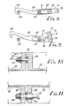
- Figure 1 is a plan view of a latch of the present invention.
- Figure 2 is a cross-sectional elevation taken along line 2-2 of Figure 1.
- Figure 3 is a schematic illustration of the positioning of the hook and handle illustrated in elevation with the latch locked in full line and unlocked in phantom.
- Figure 4 is an elevation view of the hook element.
- Figure 5 is a plan view of the hook element of Figure 4.
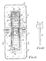
- Figure 6 is a plan view of the latch of the present invention with the underlying elements illustrated in hidden line.
- Figure 7 is a cross-sectional end view taken along line 7-7 of Figure 6.
- Figure 8 is a schematic elevation view of the hook and overcenter mechanism of the present invention in its locked position.
- Figure 9 is a schematic elevation view of the hook and overcenter mechanism of the present invention in its unlocked position.
- Figure 10 illustrates a mounting seat in cross-sectional plan view which may be employed to one side of the latch.
- Figure 11 illustrates a mounting seat and sheer pin in cross-sectional plan view which may also be used with the latching mechanism of the present invention.
- Figure 12 is a plan view of a compression link and pin of the overcenter mechanism of the present invention.
- Turning in detail to the drawings, two objects such as
aircraft panels 10 and 12 are shown to be fixed to mountingframes mounting frames mounting flange flanges mounting frames back portion 26 of the dependingflange 24 is structurally enhanced to provide mounting for a keeper.Mating flanges seating elements seating element 32 provides a flat seat defined by a series ofwashers 36 positioned by abolt 38 andnut 40. Theseating element 34 is similarly configured but further includes asheer pin 42 which extends from the end of thebolt 38 and cooperates with ahole 44 having agrommet 46 positioned therein. - Turning to the latch mechanism positioned within the
mounting frames keeper 48 is coupled with theback portion 26 of the dependingflange 24. Thekeeper 48 includes afront bar 50 for receipt of a hook. Thekeeper 48 is generally constructed as a clevis having a threadedelement 52 cooperating with anadjustment nut 54. Theadjustment nut 54 includes anadjustment wheel 56 which is exposed to the surface of the latching mechanism for manipulation by a tool.Antirotation members 58 can be seen in Figure 7 to resist rotation of thekeeper 48. - Cooperating with the
keeper 48 is a hook assembly. This assembly is mounted to themounting frame 14 by means of amounting pin 60. Themounting pin 60 extends across theU-shaped depending flange 22. Surrounding themounting pin 60 is a bushing 62. - Positioned about the mounting
pin 60 and bushing 62 between the sides of the dependingflanges 22 is ahook 64. Thehook 64 includes ahook element 66 which cooperates with thebar 50 of thekeeper 48. The body of the hook extends from thehook element 66 in a direction substantially away from thekeeper 48. Aslot 68 extends laterally through the body of thehook 64. The sides of theslot 68 are spaced apart to receive themounting pin 60 and bushing 62 such that there is very little lateral movement of thehook 64 relative to themounting pin 60. Theslot 68 extends along the body of thehook 64 to a sufficient extent that thehook 64 is effectively unconstrained in its longitudinal movement relative to themounting pin 60. Thehook 64 also includes an integral mounting bushing 70 at an end opposite to thehook element 66. Thisbushing 70 extends generally parallel to the mountingpin 60 when engaged in theslot 68 of thehook 64. - Mounting the
hook 64 to themounting pin 60 is an overcenter mechanism. The overcenter mechanism includes left and right components located to either side of thehook 64. First compression links 72 are pivotally mounted at one end to the mountingpin 60. The twolinks 72 are arranged to either side of thehook 64. Second compression links 74 are pivotally mounted at one end to ashaft 76 positioned through the integral mountingbushing 70 of thehook 64. Again, twocompression links 74 are employed and spaced apart by thehook 64. Eachfirst compression link 72 andsecond compression link 74 are joined bypins 78 about a mutual pivot axis respectively. This axis is displaced on each link from the attachments to the mountingpin 60 and theshaft 76. - Associated with the
pins 78 and located to either side of thehook 64 arebosses 80. Thebosses 80 are located inwardly of thelinks hook 64 includes twoseats 82 which are recessed into thehook 64 on either side thereof. Theseseats 82 extend down into thehook 64 in a direction perpendicular to the mutual pivot axis of the overcenter mechanism as defined by thepins 78. - A
handle 84 is pivotally mounted about theshaft 76 at the integral mountingbushing 70. The handle is generally U-shaped in cross section extending down about thehook 64 and the overcenter mechanism defined by the compression links 72 and 74. On either side of thehandle 84 and displaced from the mounting axis of the handle are twoslots 86. Theslots 86 receive thepins 78 extending outwardly from the overcenter mechanism to either side of thehook 64. Theseslots 86 provide lost motion between thehandle 84 and thepins 78 such that the overcenter mechanism may remain in the locked condition with the handle extending upwardly from its locked, flush position. At the same time, theslots 86 prevent the overcenter mechanism from unlocking when the handle is in the flush position. - Associated with the
handle 84 is alock 88. Thelock 88 is pivotally mounted to thehandle 84 about ashaft 89. Thelock 88 is generally U-shaped in cross section with two dependinghooks 90 which cooperate with a laterally extendingpin 92 in thehook 64. - To bias the elements of the locking mechanism torsional springs are employed. A
first spring 94 is wrapped about theshaft 76 and is compressed between thehandle 84 and thehook 64. Thehandle 84 is biased by thetorsional spring 94 into a position displaced upwardly from a flush position. Similarly, thehook 64 is biased by thespring 94 toward thekeeper 48. Thetorsional spring 96 is wrapped about theshaft 89 and biases thelock 88 into engagement with thepin 92. Cam surfaces 98 on thehooks 90 act to override thetorsional spring 96 when thehandle 84 is brought into a flush condition. Once thepin 92 passes across the cam surfaces 98, thelock 88 is returned by thetorsional spring 96 to the locked condition as seen in Figure 2. - As illustrated in the Figures, certain positional relationships exist between the various components. The mounting
pin 60 defining a first pivot axis is found to be parallel to the mutual pivot axis defined by thepins 78 and to a second pivot axis defined by theshaft 76. Theseats 82 receiving thebosses 80 are arranged such that when seated, the bosses are on one side of a plane passing through the first and second pivot axes. In this locked condition, this centerline of the mutual pivot axis for the overcenter mechanism is located on the opposite side of that same plane from thekeeper 48. A plane defined by the first pivot axis through the mountingpin 60 and the mutual pivot axis through thepins 78 is preferably also inclined such that it passes to the same side of thekeeper 48 as the plane extending through the first and second pivot axes. - Thus, an improved low profile aircraft panel latching mechanism is disclosed. While embodiments and applications of this invention have been shown and described, it would be apparent to those skilled in the art that many more modifications are possible without departing from the inventive concepts herein. The invention, therefore is not to be restricted except in the spirit of the appended claims.
Claims (8)
- A latching mechanism for joining two members, comprising
a keeper attached to one member;
a hook adapted to engage said keeper;
a mounting pin attached to the other member;
an overcenter linkage including a first compression link pivotally mounted to said mounting pin about a first pivot axis and a second compression link pivotally mounted to said hook about a second pivot axis, said first and second compression links being pivotally linked together at a mutual pivot axis displaced from said first and second pivot axes, said hook having a slot receiving said mounting pin. - The latch assembly of claim 1 wherein said slot is elongate along the length of said hook.
- The latch assembly of claim 1 wherein the sides of said slot constrain lateral movement of said hook at said mounting pin.
- The latch assembly of claim 3 wherein said slot extends to permit movement of said hook without constraint along the length of said hook.
- The latch assembly of claim 1 wherein said overcenter linkage further includes a boss displaced from said first and second pivot axes, said hook including a seat to receive said boss.
- The latch assembly of claim 5 wherein said boss is at the mutual pivot axis of said first and second compression links.
- The latch assembly of claim 5 or claim 6 wherein said seat is recessed into said hook in a direction perpendicular to the mutual pivot axis of said first and second compression links.
- The latch assembly of claim I wherein said hook includes a hook portion and a body, said slot extending toward and away from said hook portion, said mounting pin extending through said slot such that said hook is pivotable about said mounting pin and is slidable relative to said mounting pin, and said first, second and mutual pivot axes being free of the other member.
Applications Claiming Priority (2)
| Application Number | Priority Date | Filing Date | Title |
|---|---|---|---|
| US445021 | 1989-12-04 | ||
| US07/445,021 US5152559A (en) | 1989-12-04 | 1989-12-04 | Latching mechanism |
Publications (3)
| Publication Number | Publication Date |
|---|---|
| EP0431769A2 true EP0431769A2 (en) | 1991-06-12 |
| EP0431769A3 EP0431769A3 (en) | 1991-10-02 |
| EP0431769B1 EP0431769B1 (en) | 1993-12-29 |
Family
ID=23767322
Family Applications (1)
| Application Number | Title | Priority Date | Filing Date |
|---|---|---|---|
| EP19900312398 Expired - Lifetime EP0431769B1 (en) | 1989-12-04 | 1990-11-14 | Latching mechanism |
Country Status (6)
| Country | Link |
|---|---|
| US (1) | US5152559A (en) |
| EP (1) | EP0431769B1 (en) |
| CA (1) | CA2029918C (en) |
| DE (1) | DE69005599T2 (en) |
| ES (1) | ES2049433T3 (en) |
| RU (1) | RU2013316C1 (en) |
Cited By (7)
| Publication number | Priority date | Publication date | Assignee | Title |
|---|---|---|---|---|
| EP1167186A1 (en) * | 2000-06-30 | 2002-01-02 | Aerospace Design Facilities Limited | Safety enhancement method and safety latch |
| FR2857400A1 (en) * | 2003-07-10 | 2005-01-14 | Hurel Hispano | Airplane structures panels connecting lock, has compression link with locking pin contacting with hook surface, situated in front of operating unit, during opening of lock |
| EP1927711A2 (en) * | 2006-11-30 | 2008-06-04 | Hartwell Corporation | Command latch and pin latch system |
| WO2012052643A1 (en) * | 2010-10-21 | 2012-04-26 | Aircelle | Locking device with mechanical detection of closing and opening |
| US9353559B2 (en) | 2014-04-22 | 2016-05-31 | Airbus Operations (Sas) | Latching system for securing two components |
| WO2016200938A1 (en) | 2015-06-08 | 2016-12-15 | Qrp, Inc. | Toggle link latch |
| EP2812519B1 (en) * | 2012-02-07 | 2023-07-12 | Southco, Inc. | Lever actuated compression latch |
Families Citing this family (30)
| Publication number | Priority date | Publication date | Assignee | Title |
|---|---|---|---|---|
| US5456365A (en) * | 1993-10-26 | 1995-10-10 | Sweco, Incorporated | Vibratory screen separator |
| US5620212A (en) * | 1995-08-28 | 1997-04-15 | Hartwell Corporation | Low profile hook latch assembly |
| US6036238A (en) * | 1996-10-30 | 2000-03-14 | The Boeing Company | Double stroke over center latch |
| US5984382A (en) * | 1998-03-13 | 1999-11-16 | Hartwell Corporation | Extended reach latch |
| US6234426B1 (en) * | 1998-12-03 | 2001-05-22 | Trw Inc. | Modular spacecraft construction requiring no tools for assembly and disassembly |
| US6279971B1 (en) | 1999-10-05 | 2001-08-28 | Hartwell Corporation | Latch with sensor |
| US6325428B1 (en) | 1999-11-10 | 2001-12-04 | Hartwell Corporation | Latch assembly including sensor |
| US6343815B1 (en) | 2000-10-04 | 2002-02-05 | Hartwell Corporation | Cinch-up latch |
| US6755448B2 (en) | 2001-06-20 | 2004-06-29 | Hartwell Corporation | Blowout latch |
| US7185926B2 (en) * | 2005-03-25 | 2007-03-06 | Hartwell Corporation | Preloaded latch mechanism |
| US7357593B1 (en) * | 2005-04-14 | 2008-04-15 | Florence Brian A | Tube connector |
| US8281542B2 (en) * | 2006-09-11 | 2012-10-09 | Dana Innovations | Mechanisms for locking and removing flush mounted inserts |
| US7843363B2 (en) * | 2007-07-12 | 2010-11-30 | Rosemount Aerospace Inc. | Mechanical latch locking detection sensors |
| US7661321B2 (en) * | 2007-09-25 | 2010-02-16 | Rosemount Aerospace Inc. | Force sensing clevis insert |
| US8356844B2 (en) * | 2007-11-26 | 2013-01-22 | Avibank Manufacturing, Inc. | Flush latch with positive lock |
| FR2927061B1 (en) * | 2008-02-01 | 2010-02-12 | Aircelle Sa | LATCHING SYSTEM FOR AIR INTAKE STRUCTURE OF A TURBOJET NACELLE |
| US8403383B2 (en) * | 2008-10-10 | 2013-03-26 | Hewlett-Packard Development Company, L.P. | Print unit latch |
| US20100264673A1 (en) * | 2009-04-21 | 2010-10-21 | Zeljko Baic | Command latch and pin latch system |
| RU2457370C1 (en) * | 2010-12-16 | 2012-07-27 | Федеральное государственное унитарное предприятие "Государственный космический научно-производственный центр им. М.В. Хруничева" | Appliance to interconnect two elements of structure |
| FR2991669B1 (en) * | 2012-06-11 | 2014-07-11 | Lisi Aerospace | HOOK LATCH |
| US9617767B1 (en) * | 2014-11-06 | 2017-04-11 | Avibank Manufacturing, Inc. | Latch mechanism |
| US20170089107A1 (en) * | 2015-09-29 | 2017-03-30 | Alcoa Inc. | Tri-links latch |
| ES2805826T3 (en) * | 2016-03-10 | 2021-02-15 | Hartwell Corp | Hook latch with high offset |
| CN109983192B (en) * | 2016-09-18 | 2022-04-08 | Qrp股份有限公司 | Safety hook type lock |
| US10399688B2 (en) * | 2016-11-09 | 2019-09-03 | Rohr, Inc. | Nacelle latch alignment |
| DE102019102491A1 (en) * | 2019-01-31 | 2020-08-06 | Hettich-Oni Gmbh & Co. Kg | Flap fitting for furniture |
| US11326378B2 (en) * | 2019-06-04 | 2022-05-10 | Rohr, Inc. | Latch and method for operating said latch |
| RU2729909C1 (en) * | 2019-12-23 | 2020-08-13 | Акционерное общество «Информационные спутниковые системы» имени академика М.Ф.Решетнёва» | Assembly for docking of spacecraft load carrying structure (versions) |
| US20240076918A1 (en) * | 2022-09-02 | 2024-03-07 | Rohr, Inc. | Latch assembly |
| CN115693547B (en) * | 2022-11-23 | 2023-10-24 | 广东宏际线管实业有限公司 | Cable bridge rack is with padlock and cable bridge rack |
Citations (5)
| Publication number | Priority date | Publication date | Assignee | Title |
|---|---|---|---|---|
| DE819796C (en) * | 1950-03-14 | 1951-11-05 | Beschlagfabrik Benninghoven | Enclosed hood lock, especially for motor vehicles |
| FR2183971A1 (en) * | 1972-05-08 | 1973-12-21 | Von Tell Trading Co Ab | |
| US4318557A (en) * | 1979-10-09 | 1982-03-09 | Hartwell Corporation | Latching mechanism |
| US4828299A (en) * | 1987-03-31 | 1989-05-09 | Hartwell Corporation | Latch |
| FR2641952A1 (en) * | 1989-01-20 | 1990-07-27 | Delsey Soc | Device for closure by means of a tilting and sliding lever, particularly for suitcases |
Family Cites Families (8)
| Publication number | Priority date | Publication date | Assignee | Title |
|---|---|---|---|---|
| US2136662A (en) * | 1937-10-18 | 1938-11-15 | Winters & Crampton Corp | Refrigerator latch |
| US2703431A (en) * | 1953-01-12 | 1955-03-08 | Jean H Tatom | Latch hinge |
| US2896751A (en) * | 1956-11-16 | 1959-07-28 | Clark Hartwell | Toggle bolt latch |
| US2894777A (en) * | 1956-12-03 | 1959-07-14 | Clark Hartwell | Preload latch |
| US2961262A (en) * | 1959-05-25 | 1960-11-22 | John P Nockels | Latch mechanism |
| US3174784A (en) * | 1962-10-22 | 1965-03-23 | Gunnar E Swanson | Fastening device |
| US3437364A (en) * | 1967-09-21 | 1969-04-08 | Keystone Consolidated Ind Inc | Sliding door lock assembly |
| CH564871A5 (en) * | 1972-05-09 | 1975-07-31 | Saia Ag |
-
1989
- 1989-12-04 US US07/445,021 patent/US5152559A/en not_active Expired - Lifetime
-
1990
- 1990-11-14 EP EP19900312398 patent/EP0431769B1/en not_active Expired - Lifetime
- 1990-11-14 CA CA 2029918 patent/CA2029918C/en not_active Expired - Lifetime
- 1990-11-14 ES ES90312398T patent/ES2049433T3/en not_active Expired - Lifetime
- 1990-11-14 DE DE1990605599 patent/DE69005599T2/en not_active Expired - Lifetime
- 1990-12-03 RU SU4831828 patent/RU2013316C1/en active
Patent Citations (5)
| Publication number | Priority date | Publication date | Assignee | Title |
|---|---|---|---|---|
| DE819796C (en) * | 1950-03-14 | 1951-11-05 | Beschlagfabrik Benninghoven | Enclosed hood lock, especially for motor vehicles |
| FR2183971A1 (en) * | 1972-05-08 | 1973-12-21 | Von Tell Trading Co Ab | |
| US4318557A (en) * | 1979-10-09 | 1982-03-09 | Hartwell Corporation | Latching mechanism |
| US4828299A (en) * | 1987-03-31 | 1989-05-09 | Hartwell Corporation | Latch |
| FR2641952A1 (en) * | 1989-01-20 | 1990-07-27 | Delsey Soc | Device for closure by means of a tilting and sliding lever, particularly for suitcases |
Cited By (17)
| Publication number | Priority date | Publication date | Assignee | Title |
|---|---|---|---|---|
| EP1167186A1 (en) * | 2000-06-30 | 2002-01-02 | Aerospace Design Facilities Limited | Safety enhancement method and safety latch |
| AU2004263697B2 (en) * | 2003-07-10 | 2009-09-17 | Aircelle | Latch for joining two panels of an airplane structure |
| FR2857400A1 (en) * | 2003-07-10 | 2005-01-14 | Hurel Hispano | Airplane structures panels connecting lock, has compression link with locking pin contacting with hook surface, situated in front of operating unit, during opening of lock |
| WO2005014962A2 (en) | 2003-07-10 | 2005-02-17 | Aircelle | Latch for joining two panels of an airplane structure |
| WO2005014962A3 (en) * | 2003-07-10 | 2005-06-09 | Hurel Hispano Sa | Latch for joining two panels of an airplane structure |
| CN100424316C (en) * | 2003-07-10 | 2008-10-08 | 埃尔塞乐公司 | Latch for joining two panels of an airplane structure |
| US7461871B2 (en) | 2003-07-10 | 2008-12-09 | Aircelle | Latch for joining two panels of an airplane structure |
| US8925979B2 (en) | 2006-11-30 | 2015-01-06 | Hartwell Corporation | Command latch and pin latch system |
| EP1927711A3 (en) * | 2006-11-30 | 2014-11-05 | Hartwell Corporation | Command latch and pin latch system |
| EP1927711A2 (en) * | 2006-11-30 | 2008-06-04 | Hartwell Corporation | Command latch and pin latch system |
| WO2012052643A1 (en) * | 2010-10-21 | 2012-04-26 | Aircelle | Locking device with mechanical detection of closing and opening |
| FR2966488A1 (en) * | 2010-10-21 | 2012-04-27 | Aircelle Sa | LOCKING DEVICE WITH MECHANICAL DETECTION OF CLOSURE AND OPENING |
| US8764072B2 (en) | 2010-10-21 | 2014-07-01 | Aircelle | Locking device with mechanical detection of closing and opening |
| EP2812519B1 (en) * | 2012-02-07 | 2023-07-12 | Southco, Inc. | Lever actuated compression latch |
| US9353559B2 (en) | 2014-04-22 | 2016-05-31 | Airbus Operations (Sas) | Latching system for securing two components |
| WO2016200938A1 (en) | 2015-06-08 | 2016-12-15 | Qrp, Inc. | Toggle link latch |
| EP3303745A4 (en) * | 2015-06-08 | 2019-03-27 | QRP, Inc. | Toggle link latch |
Also Published As
| Publication number | Publication date |
|---|---|
| ES2049433T3 (en) | 1994-04-16 |
| CA2029918C (en) | 1996-01-02 |
| EP0431769B1 (en) | 1993-12-29 |
| EP0431769A3 (en) | 1991-10-02 |
| RU2013316C1 (en) | 1994-05-30 |
| US5152559A (en) | 1992-10-06 |
| DE69005599T2 (en) | 1994-04-28 |
| DE69005599D1 (en) | 1994-02-10 |
| CA2029918A1 (en) | 1991-06-05 |
Similar Documents
| Publication | Publication Date | Title |
|---|---|---|
| US5152559A (en) | Latching mechanism | |
| EP0901426B1 (en) | Center pivot bracket assembly for pivoting the rear seat of a vehicle | |
| US5564295A (en) | Handle operable rotary latch and lock | |
| US4602812A (en) | Adjustable double hook latch | |
| US4892338A (en) | Plural point door lock and flush-mountable operating mechanism with detent | |
| US6412849B1 (en) | Chuck-free latch assembly | |
| US4896906A (en) | Vehicle door lock system | |
| US6651467B1 (en) | T-handle operable rotary latch and lock | |
| US4243342A (en) | Snap fast fastener | |
| JPH0583712B2 (en) | ||
| US4811983A (en) | Gas spring with latching stop mechanism for use on skid-steer loaders | |
| JPH0516519B2 (en) | ||
| US20020040828A1 (en) | Ladder mounting system | |
| US4320912A (en) | Cowl door latch adjustment fitting assembly | |
| US20210300579A1 (en) | Latching system with movable anti-shear mechanism | |
| US20060061108A1 (en) | Aircraft latch | |
| EP0306223B1 (en) | Latch handle assembly | |
| US4991885A (en) | Trigger lock cam | |
| US20040113440A1 (en) | Latch assembly for movable closure element | |
| US7175209B2 (en) | Clip for holding a release lever of a vehicle latch during shipping | |
| EP0021743A1 (en) | Lock for a tiltable truck cab and vehicles including such locks | |
| CN209938381U (en) | Lock structure for backrest of car seat | |
| KR200209224Y1 (en) | Cargo Lock Locks | |
| US20220127876A1 (en) | Interior Handle for Upward Acting Vehicle Door | |
| JPH0751574Y2 (en) | Lock device striker structure |
Legal Events
| Date | Code | Title | Description |
|---|---|---|---|
| PUAI | Public reference made under article 153(3) epc to a published international application that has entered the european phase |
Free format text: ORIGINAL CODE: 0009012 |
|
| AK | Designated contracting states |
Kind code of ref document: A2 Designated state(s): CH DE ES FR GB IT LI NL |
|
| PUAL | Search report despatched |
Free format text: ORIGINAL CODE: 0009013 |
|
| AK | Designated contracting states |
Kind code of ref document: A3 Designated state(s): CH DE ES FR GB IT LI NL |
|
| 17P | Request for examination filed |
Effective date: 19910830 |
|
| 17Q | First examination report despatched |
Effective date: 19921026 |
|
| GRAA | (expected) grant |
Free format text: ORIGINAL CODE: 0009210 |
|
| AK | Designated contracting states |
Kind code of ref document: B1 Designated state(s): CH DE ES FR GB IT LI NL |
|
| REF | Corresponds to: |
Ref document number: 69005599 Country of ref document: DE Date of ref document: 19940210 |
|
| ET | Fr: translation filed | ||
| ITF | It: translation for a ep patent filed |
Owner name: PROPRIA PROT. PROPRIETA' IND. |
|
| REG | Reference to a national code |
Ref country code: ES Ref legal event code: FG2A Ref document number: 2049433 Country of ref document: ES Kind code of ref document: T3 |
|
| PLBE | No opposition filed within time limit |
Free format text: ORIGINAL CODE: 0009261 |
|
| STAA | Information on the status of an ep patent application or granted ep patent |
Free format text: STATUS: NO OPPOSITION FILED WITHIN TIME LIMIT |
|
| 26N | No opposition filed | ||
| REG | Reference to a national code |
Ref country code: GB Ref legal event code: IF02 |
|
| PGFP | Annual fee paid to national office [announced via postgrant information from national office to epo] |
Ref country code: CH Payment date: 20021021 Year of fee payment: 13 |
|
| PG25 | Lapsed in a contracting state [announced via postgrant information from national office to epo] |
Ref country code: CH Free format text: LAPSE BECAUSE OF NON-PAYMENT OF DUE FEES Effective date: 20031130 Ref country code: LI Free format text: LAPSE BECAUSE OF NON-PAYMENT OF DUE FEES Effective date: 20031130 |
|
| REG | Reference to a national code |
Ref country code: CH Ref legal event code: PL |
|
| PGFP | Annual fee paid to national office [announced via postgrant information from national office to epo] |
Ref country code: DE Payment date: 20091127 Year of fee payment: 20 Ref country code: ES Payment date: 20091126 Year of fee payment: 20 |
|
| PGFP | Annual fee paid to national office [announced via postgrant information from national office to epo] |
Ref country code: NL Payment date: 20091123 Year of fee payment: 20 |
|
| PGFP | Annual fee paid to national office [announced via postgrant information from national office to epo] |
Ref country code: IT Payment date: 20091128 Year of fee payment: 20 Ref country code: GB Payment date: 20091125 Year of fee payment: 20 Ref country code: FR Payment date: 20091201 Year of fee payment: 20 |
|
| REG | Reference to a national code |
Ref country code: NL Ref legal event code: V4 Effective date: 20101114 |
|
| REG | Reference to a national code |
Ref country code: GB Ref legal event code: PE20 Expiry date: 20101113 |
|
| PG25 | Lapsed in a contracting state [announced via postgrant information from national office to epo] |
Ref country code: NL Free format text: LAPSE BECAUSE OF EXPIRATION OF PROTECTION Effective date: 20101114 |
|
| REG | Reference to a national code |
Ref country code: ES Ref legal event code: FD2A Effective date: 20110225 |
|
| PG25 | Lapsed in a contracting state [announced via postgrant information from national office to epo] |
Ref country code: GB Free format text: LAPSE BECAUSE OF EXPIRATION OF PROTECTION Effective date: 20101113 |
|
| PG25 | Lapsed in a contracting state [announced via postgrant information from national office to epo] |
Ref country code: ES Free format text: LAPSE BECAUSE OF EXPIRATION OF PROTECTION Effective date: 20101115 |
|
| PG25 | Lapsed in a contracting state [announced via postgrant information from national office to epo] |
Ref country code: DE Free format text: LAPSE BECAUSE OF EXPIRATION OF PROTECTION Effective date: 20101114 |