EP0431070B1 - Sheet-film cassette - Google Patents
Sheet-film cassette Download PDFInfo
- Publication number
- EP0431070B1 EP0431070B1 EP89910445A EP89910445A EP0431070B1 EP 0431070 B1 EP0431070 B1 EP 0431070B1 EP 89910445 A EP89910445 A EP 89910445A EP 89910445 A EP89910445 A EP 89910445A EP 0431070 B1 EP0431070 B1 EP 0431070B1
- Authority
- EP
- European Patent Office
- Prior art keywords
- cassette
- hinge
- projection
- sheet
- film
- Prior art date
- Legal status (The legal status is an assumption and is not a legal conclusion. Google has not performed a legal analysis and makes no representation as to the accuracy of the status listed.)
- Expired - Lifetime
Links
Images

Classifications
-
- G—PHYSICS
- G03—PHOTOGRAPHY; CINEMATOGRAPHY; ANALOGOUS TECHNIQUES USING WAVES OTHER THAN OPTICAL WAVES; ELECTROGRAPHY; HOLOGRAPHY
- G03B—APPARATUS OR ARRANGEMENTS FOR TAKING PHOTOGRAPHS OR FOR PROJECTING OR VIEWING THEM; APPARATUS OR ARRANGEMENTS EMPLOYING ANALOGOUS TECHNIQUES USING WAVES OTHER THAN OPTICAL WAVES; ACCESSORIES THEREFOR
- G03B42/00—Obtaining records using waves other than optical waves; Visualisation of such records by using optical means
- G03B42/02—Obtaining records using waves other than optical waves; Visualisation of such records by using optical means using X-rays
- G03B42/04—Holders for X-ray films
Definitions
- the invention relates to a sheet-film cassette
- a sheet-film cassette comprising a lower cassette portion serving to position the sheet film, an upper cassette portion forming the cassette lid and including sheet-film pressure means, a narrow side wall connected to said lower portion, said upper cassette portion being held to said side wall, and thereby to said lower cassette portion, by a hinge, said hinge extending in a direction parallel to said side wall and having a surface aligned with the outer surface of said side wall, one part of the hinge being connected to the side wall, a second part of the hinge being connected to the upper cassette portion, the cassette also having a closing device which is arranged on the side of the cassette opposite to said hinge, the hinge further comprising a first projection, which extends from the part of the hinge connected to the side wall in a direction parallel with the hinge and projects into the interior of the cassette, a second projection which extends from the part of the hinge connected to the upper cassette portion in a direction parallel with the first projection and projects into the interior of the cassette.
- the cassette lid is hinged to the lower cassette portion by a hinge made of flexible material and comprising a pivot zone formed by a thinned section and having two claw-like holding elements to connect the cassette portions.
- the cassette lid is hinged to the lower cassette portion by a plastic hinge, a flexible pivot zone being formed by a thinned section of the material at the hinge.
- the hinge is fastened to a thin wall of the lower cassette portion which in a manner known per se serves for positioning the cassette and for moving an X-ray film into close contact with a portion adapted to receive said film.
- this object is attained in that when the cassette is closed the second projection engages the first projection from below, whereby the projections support each other.
- the hinge consists of a flexible material and has a ledge-shaped profile with a pivot zone formed by a thinned section of the material. Holding elements extending in the longitudinal direction on either side of said pivot zone are provided for the cassette portions as well as for the projections required for the support according to the invention and for further elements provided for light-sealing purposes.
- the cassette which is unstable in the area of the thin wall and the pivot zone of the hinge when in its open position, is stabilized when the cassette is closed.
- the cassette lid and its pressure means respectively can exert uniform pressure on the film across the whole length of the hinge.
- the invention will be described with reference to an X-ray sheet-film cassette which is preferably used for mamographic purposes and to this end is designed with a relatively thin end wall so that the Xray film can be moved as closely as possible to the body.
- the cassette 1 comprises a lower portion 2 to which a lid 3 is hinged by means of a hinge 4.
- Lid 3 can be locked with a lower portion 2 of cassette 1 by means of a closing device 7 of a type known per se and not illustrated in detail, which can be actuated either automatically or manually.
- the lower portion 2 of cassette 1 has a support surface 2d for a sheet film 10, said support surface being surrounded by a circumferential wall 2a, 2b of which wall portion 2b is thin and directly forms the outer wall of a narrow side of cassette 1.
- Two spring elements 5, 6 are mounted to the lower portion 2 in a position opposite to the thin wall 2b (Fig. 2) by hot rivets 11 with a slight pretention. As illustrated in Fig. 3, the free ends of the spring elements 5, 6 extend into the closed receiving space for the sheet film 10 and into recesses 2e of the support surface 2d.
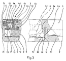
- Hinge 4 by which the lower portion 2 and the lid 3 are pivotably connected consists of a flexible material and, as shown in Fig. 3, has a ledge-shaped profile with a thinned section which forms a pivot zone 4i. Holding elements extending over the whole length of the hinge are molded on either side of said pivot zone 4i for mounting the lower portion 2 and the lid 3 respectively. On the side of the lid, these holding elements are formed by ledges 4a, 4b which enclose in a clawlike manner a T-shaped end section 3c of lid 3.
- Ledges 4f and 4h molded to hinge 4 also enclose also in a clawlike manner a beadlike portion 2f of thin wall 2b of lower portion 2.
- hinge 4 extends over the total length of hinge 4 so that the hinge is protected against the entrance of light when cassette 1 is closed.
- the end sides of hinge 4 are, moreover, covered by lateral projections 3a and 3b of lid 3 (see Fig. 2) as well as by intermediate labyrinth-type webs (not illustrated) on the lower portion 2 and are thus sealed against the entrance of light.
- Hinge 4 does not project beyond the plane of the outer surface 2c of the lower portion 2. Hinge 4 is fastened on the lower portion 2 and on lid 3 by plugging and/or snapping.
- film pressure means of a type known per se are provided, said means comprising a foamed-plastic plate 8 and an intensifying screen 9 arranged thereon and extending directly up to the inner surface 2g of the thin wall 2b.
- the foamed-plastic plate 8 is mounted on the inner side of lid 3, which is not shown in detail, and is reinforced by ribs 3d arranged in a grid pattern.
- the lower portion 2 and the lid 3 of cassette 1 are provided with walls interlocking in a known labyrinth-type configuration not illustrated to prevent light from entering the cassette.
- lid 3 When lid 3 is closed, one of those walls 3e arranged on lid 3 (see Fig. 3) extends into the range of pivotal movement of the spring elements 5 and 6 and displaces said elements laterally.
- the obliquely positioned spring elements 5, 6 (shown in dash-dotted lines) direct the sheet film 10 into the receiving chamber of the cassette 1 such that its front edge is moved into direct contact with the inner surface 2g of thin wall 2b.
- lid 3 is closed. During such operation ledge 4d associated with lid 3 moves below ledge 4f associated with the thin wail 2b of lower portion 2 so that the inclined surfaces 4e and 4g of said ledges are brought into positive engagement.
- lid 3 is reliably supported and the whole area of the hinge is stabilized so that lid 3 exerts uniform pressure over the total width of the cassette.
- the inclined surface 4g of ledge 4f acts on the inclined surface 4e of ledge 4d to press lid 3 together with foamed-plastic plate 8 and intensifying screen 9 onto sheet film 10 placed in lower portion 2, 2d.
- the relatively high initial pressure results in the intimate contact required between intensifying screen 9 and sheet film 10.
- the rolling effect between sheet film 10 and pressure means 8 and 9 initiated during closing of the lid 3 - and subjecting the surface to low pressure - is continued due to a slightly curved design of the inner side of lid 3 (not illustrated) and a slightly drum-shaped design of the support surface 2d in the lower portion 2 (not illustrated either) until cassette 1 is closed. Thanks to the rolling effect during closing of cassette 1, air cannot be entrapped between sheet film 10 and its contact surfaces 2d and 9.
- one of the longer sides of the hinge can also be molded directly to the lid or to the lower portion.
- the lower portion, the hinge and the lid can form an integral unit (not illustrated).
- FIG. 1 Another modification of the illustrated embodiment may consist in that (not illustrated) one or both support ledges 4d, 4f form part of lower portion 2 and cassette lid 3 respectively, with the hinge 4 otherwise designed in the described manner or in another manner known per se.
- the design of the hinge area according to the invention is advantageous not only for a cassette as shown in the embodiment but also for a cassette in which the hinge area must be stabilized in order to attain smaller cassette dimensions.
Landscapes
- Physics & Mathematics (AREA)
- General Physics & Mathematics (AREA)
- Packaging Of Annular Or Rod-Shaped Articles, Wearing Apparel, Cassettes, Or The Like (AREA)
- Radiography Using Non-Light Waves (AREA)
Abstract
Description
- The invention relates to a sheet-film cassette comprising a lower cassette portion serving to position the sheet film, an upper cassette portion forming the cassette lid and including sheet-film pressure means, a narrow side wall connected to said lower portion, said upper cassette portion being held to said side wall, and thereby to said lower cassette portion, by a hinge, said hinge extending in a direction parallel to said side wall and having a surface aligned with the outer surface of said side wall, one part of the hinge being connected to the side wall, a second part of the hinge being connected to the upper cassette portion, the cassette also having a closing device which is arranged on the side of the cassette opposite to said hinge, the hinge further comprising a first projection, which extends from the part of the hinge connected to the side wall in a direction parallel with the hinge and projects into the interior of the cassette, a second projection which extends from the part of the hinge connected to the upper cassette portion in a direction parallel with the first projection and projects into the interior of the cassette.
- In a cassette of this type which has been disclosed in DE-C1-34 01 577 the cassette lid is hinged to the lower cassette portion by a hinge made of flexible material and comprising a pivot zone formed by a thinned section and having two claw-like holding elements to connect the cassette portions.
- According to another cassette (PCT-A1-WO 82/00900) the cassette lid is hinged to the lower cassette portion by a plastic hinge, a flexible pivot zone being formed by a thinned section of the material at the hinge. The hinge is fastened to a thin wall of the lower cassette portion which in a manner known per se serves for positioning the cassette and for moving an X-ray film into close contact with a portion adapted to receive said film.
- As a result of the thin wall of these cassettes and the thinned flexible zone of their hinges, the stability of these cassettes in the area of the hinge is reduced so that uniform contact pressure of the film cannot be guaranteed.
- It is the object of the invention to provide a sheet-film cassette of the generic type such that in the area of the casette hinge, too, a uniform contact pressure by a cassette lid on the film is reached over the whole length of the hinge.
- In accordance with the invention this object is attained in that when the cassette is closed the second projection engages the first projection from below, whereby the projections support each other.
- Avantageously, the hinge consists of a flexible material and has a ledge-shaped profile with a pivot zone formed by a thinned section of the material. Holding elements extending in the longitudinal direction on either side of said pivot zone are provided for the cassette portions as well as for the projections required for the support according to the invention and for further elements provided for light-sealing purposes.
- As a result of the design of the sheet-film cassette according to the invention, the cassette, which is unstable in the area of the thin wall and the pivot zone of the hinge when in its open position, is stabilized when the cassette is closed. Thus the cassette lid and its pressure means respectively can exert uniform pressure on the film across the whole length of the hinge.
- Further features and advantages can be inferred from the description of an embodiment of the invention illustrated in the drawings and from the subclaims.
- The drawings show schematically in
- Fig. 1
- a lateral view of a sheet-film cassette;
- Fig. 2
- a plan view of the cassette according to Fig. 1, and
- Fig. 3
- a sectional view along line A-A in Fig. 2, with only the essential areas illustrated and shown in section respectively.
- The invention will be described with reference to an X-ray sheet-film cassette which is preferably used for mamographic purposes and to this end is designed with a relatively thin end wall so that the Xray film can be moved as closely as possible to the body.
- The cassette 1 comprises a
lower portion 2 to which alid 3 is hinged by means of ahinge 4. -
Lid 3 can be locked with alower portion 2 of cassette 1 by means of aclosing device 7 of a type known per se and not illustrated in detail, which can be actuated either automatically or manually. - The
lower portion 2 of cassette 1 has asupport surface 2d for asheet film 10, said support surface being surrounded by acircumferential wall wall portion 2b is thin and directly forms the outer wall of a narrow side of cassette 1. - Two
spring elements 5, 6 are mounted to thelower portion 2 in a position opposite to thethin wall 2b (Fig. 2) byhot rivets 11 with a slight pretention. As illustrated in Fig. 3, the free ends of thespring elements 5, 6 extend into the closed receiving space for thesheet film 10 and intorecesses 2e of thesupport surface 2d. -
Hinge 4 by which thelower portion 2 and thelid 3 are pivotably connected consists of a flexible material and, as shown in Fig. 3, has a ledge-shaped profile with a thinned section which forms a pivot zone 4i. Holding elements extending over the whole length of the hinge are molded on either side of said pivot zone 4i for mounting thelower portion 2 and thelid 3 respectively. On the side of the lid, these holding elements are formed byledges lid 3. -
Ledges thin wall 2b oflower portion 2. - As can be seen from Fig. 3, when the cassette 1 is closed, the area of the hinge is stabilized by a
ledge 4d associated withlid 3, said ledge having aninclined surface 4e which positively engages below aninclined surface 4g ofledge 4f which is associated with thethin wall 2b. - The ledges 4d and 4f and a projection 4j extending into a recess 4k, which are also molded on
hinge 4, extend over the total length ofhinge 4 so that the hinge is protected against the entrance of light when cassette 1 is closed. The end sides ofhinge 4 are, moreover, covered bylateral projections lower portion 2 and are thus sealed against the entrance of light. - Hinge 4 does not project beyond the plane of the outer surface 2c of the
lower portion 2. Hinge 4 is fastened on thelower portion 2 and onlid 3 by plugging and/or snapping. - At the inner side of
lid 3, film pressure means of a type known per se are provided, said means comprising a foamed-plastic plate 8 and an intensifyingscreen 9 arranged thereon and extending directly up to theinner surface 2g of thethin wall 2b. - The foamed-
plastic plate 8 is mounted on the inner side oflid 3, which is not shown in detail, and is reinforced byribs 3d arranged in a grid pattern. - Outside the range of the hinge, the
lower portion 2 and thelid 3 of cassette 1 are provided with walls interlocking in a known labyrinth-type configuration not illustrated to prevent light from entering the cassette. Whenlid 3 is closed, one of thosewalls 3e arranged on lid 3 (see Fig. 3) extends into the range of pivotal movement of thespring elements 5 and 6 and displaces said elements laterally. - When a
sheet film 10 is loaded into the open cassette 1, the obliquely positionedspring elements 5, 6 (shown in dash-dotted lines) direct thesheet film 10 into the receiving chamber of the cassette 1 such that its front edge is moved into direct contact with theinner surface 2g ofthin wall 2b. - When
sheet film 10 is in its loaded position, its rear edge assumes a slightly elevated position as shown in dash-dotted lines in Fig. 3. This ensures that thespring elements 5, 6 can always carry out their guiding function independently of the dimensional tolerances of the film. - The
sheet film 10 having been loaded,lid 3 is closed. Duringsuch operation ledge 4d associated withlid 3 moves belowledge 4f associated with thethin wail 2b oflower portion 2 so that theinclined surfaces - As a result,
lid 3 is reliably supported and the whole area of the hinge is stabilized so thatlid 3 exerts uniform pressure over the total width of the cassette. - During closing of
lid 3, theinclined surface 4g ofledge 4f acts on theinclined surface 4e ofledge 4d to presslid 3 together with foamed-plastic plate 8 and intensifyingscreen 9 ontosheet film 10 placed inlower portion screen 9 andsheet film 10. The rolling effect betweensheet film 10 and pressure means 8 and 9 initiated during closing of the lid 3 - and subjecting the surface to low pressure - is continued due to a slightly curved design of the inner side of lid 3 (not illustrated) and a slightly drum-shaped design of thesupport surface 2d in the lower portion 2 (not illustrated either) until cassette 1 is closed. Thanks to the rolling effect during closing of cassette 1, air cannot be entrapped betweensheet film 10 and itscontact surfaces - Shortly before
lid 3 reaches its closing position, thespring elements 5, 6, which are not used any longer, are pushed aside by thewall 3e of the lid so that thesheet film 10 can assume a perfectly plane position also in this area when cassette 1 is closed. - In contrast to the illustrated embodiment one of the longer sides of the hinge can also be molded directly to the lid or to the lower portion. Moreover, it is possible for the lower portion, the hinge and the lid to form an integral unit (not illustrated).
- Another modification of the illustrated embodiment may consist in that (not illustrated) one or both support ledges 4d, 4f form part of
lower portion 2 andcassette lid 3 respectively, with thehinge 4 otherwise designed in the described manner or in another manner known per se. - The design of the hinge area according to the invention is advantageous not only for a cassette as shown in the embodiment but also for a cassette in which the hinge area must be stabilized in order to attain smaller cassette dimensions.
Claims (8)
- Sheet-film cassette (1) comprising a lower cassette portion (2) serving to position the sheet film (10), an upper cassette portion (3) forming the cassette lid and including sheet-film pressure means (8), a narrow side wall (2b) connected to said lower portion (2), said upper cassette portion (3) being held to said side wall (2b), and thereby to said lower cassette portion (2), by a hinge (4), said hinge (4) extending in a direction parallel to said side wall (2b) and having a surface aligned with the outer surface (2c) of said side wall (2b), one part of the hinge being connected to the side wail, a second part of the hinge being connected to the upper cassette portion, the cassette (1) also having a closing device (7) which is arranged on the side of the cassette opposite to said hinge (4), the hinge (4) further comprising a first projection (4f), which extends from the part of the hinge (4) connected to the side wall (2b) in a direction parallel with the hinge (4) and projects into the interior of the cassette, a second projection (4d) which extends from the part of the hinge (4) connected to the upper cassette portion (3) in a direction parallel with the first projection (4f) and projects into the interior of the cassette, characterized in that when the cassette is closed the second projection (4d) engages the first projection (4f) from below, whereby the projections (4d, 4f) support each other.
- Sheet-film cassette according to claim 1, characterized in that the contact areas of the first and the second projection (4d, 4f) have inclined surfaces (4e, 4g) which allow the cassette lid (3) to carry out an unobstructed pivotal movement.
- Sheet-film cassette according to claim 1 or 2, characterized in that the contact areas (4e, 4g) of the first and second projections (4d, 4f) engage in a light-sealing manner.
- Sheet-film cassette according to one or several of claims 1 to 3, characterized in that the hinge (4), which consists of a flexible material, comprises a pivot zone (4i) formed by a thinned section of the material and claw-like holding elements (4a, 4b; 4f, 4h) arranged on either side of said zone and associated with the cassette portions (2, 3).
- Sheet-film cassette according to claim 4, characterized in that the hinge (4) has a ledge-shaped profile with holding elements (4a, 4b, 4f, 4h) extending in the longitudinal direction, projections (4d, 4f, 4j), inclined surfaces (4e, 4g) and a recess (4k).
- Sheet-film cassette according to claims 4 and 5, characterized in that the claw-like holding elements (4a, 4b; 4f, 4h) engage correspondingly molded structures (2f; 3c) on the lower cassette portion (2) and on the cassette lid (3) respectively.
- Sheet-film cassette according to one or several of claims 1 to 6, characterized in that the first projection (4f) is arranged on the holding element (4f, 4h) of hinge (4), which is associated with the lower cassette portion (2), and the second projection (4d) is arranged on the holding element (4a, 4b), which is associated with the cassette lid (3).
- Sheet-film cassette according to one or several of claims 1 to 7, characterized in that a third projection (4j) is arranged on the holding element (4f, 4h) associated with the lower cassette portion (2), which third projection covers the first projection (4f) and is arranged parallel therewith and extends further into the interior of the cassette, and in that when cassette (1) is in its closed condition, the third projection (4j) engages in a labyrinth-like fashion an associated recess (4k) in the holding element (4a, 4b) associated with cassette lid (3).
Priority Applications (1)
| Application Number | Priority Date | Filing Date | Title |
|---|---|---|---|
| AT89910445T ATE96551T1 (en) | 1988-08-30 | 1989-08-28 | SHEET FILM CASSETTE. |
Applications Claiming Priority (2)
| Application Number | Priority Date | Filing Date | Title |
|---|---|---|---|
| DE3829313A DE3829313C2 (en) | 1988-08-30 | 1988-08-30 | PLAN FILM CASSETTE |
| DE3829313 | 1988-08-30 |
Publications (2)
| Publication Number | Publication Date |
|---|---|
| EP0431070A1 EP0431070A1 (en) | 1991-06-12 |
| EP0431070B1 true EP0431070B1 (en) | 1993-10-27 |
Family
ID=6361836
Family Applications (1)
| Application Number | Title | Priority Date | Filing Date |
|---|---|---|---|
| EP89910445A Expired - Lifetime EP0431070B1 (en) | 1988-08-30 | 1989-08-28 | Sheet-film cassette |
Country Status (4)
| Country | Link |
|---|---|
| US (1) | US5146484A (en) |
| EP (1) | EP0431070B1 (en) |
| DE (2) | DE3829313C2 (en) |
| WO (1) | WO1990002356A1 (en) |
Families Citing this family (4)
| Publication number | Priority date | Publication date | Assignee | Title |
|---|---|---|---|---|
| DE9101332U1 (en) * | 1991-02-06 | 1991-04-25 | Agfa-Gevaert Ag, 5090 Leverkusen | Plastic profile hinge for X-ray sheet film cassettes |
| US5388140A (en) * | 1993-06-30 | 1995-02-07 | Eastman Kodak Company | Film cassette |
| US5684853A (en) * | 1994-05-24 | 1997-11-04 | Minnesota Mining And Manufacturing Company | Flexible radiographic cassette holder |
| US5652781A (en) * | 1996-04-24 | 1997-07-29 | Eastman Kodak Company | Intensifying x-ray film cassette |
Family Cites Families (4)
| Publication number | Priority date | Publication date | Assignee | Title |
|---|---|---|---|---|
| DE2917547C2 (en) * | 1979-04-30 | 1981-11-19 | Agfa-Gevaert Ag, 5090 Leverkusen | X-ray film cassette |
| DE3401577C1 (en) * | 1984-01-18 | 1985-05-30 | Agfa-Gevaert Ag, 5090 Leverkusen | Roentgenblattfilmkassette for shooting angled body parts |
| DE3402202C1 (en) * | 1984-01-24 | 1985-06-27 | Agfa-Gevaert Ag, 5090 Leverkusen | X-ray sheet film cassette |
| DE8910348U1 (en) * | 1989-08-30 | 1989-10-19 | Agfa-Gevaert Ag, 5090 Leverkusen | X-ray sheet film cassette |
-
1988
- 1988-08-30 DE DE3829313A patent/DE3829313C2/en not_active Expired - Fee Related
-
1989
- 1989-08-28 EP EP89910445A patent/EP0431070B1/en not_active Expired - Lifetime
- 1989-08-28 DE DE89910445T patent/DE68910324T2/en not_active Expired - Fee Related
- 1989-08-28 WO PCT/EP1989/001009 patent/WO1990002356A1/en not_active Ceased
- 1989-08-28 US US07/646,599 patent/US5146484A/en not_active Expired - Lifetime
Also Published As
| Publication number | Publication date |
|---|---|
| WO1990002356A1 (en) | 1990-03-08 |
| US5146484A (en) | 1992-09-08 |
| DE68910324D1 (en) | 1993-12-02 |
| DE3829313C2 (en) | 1993-11-04 |
| DE3829313A1 (en) | 1990-03-08 |
| DE68910324T2 (en) | 1994-05-11 |
| EP0431070A1 (en) | 1991-06-12 |
Similar Documents
| Publication | Publication Date | Title |
|---|---|---|
| USRE35284E (en) | X-ray sheet film cassette for application to angular body parts | |
| US4834246A (en) | Toner cartridge | |
| US5146484A (en) | Sheet-film cassette | |
| US4383330A (en) | X-Ray cassette having quick film release mechanism | |
| US4493545A (en) | Film cassette | |
| JPS5943743A (en) | Moisture proof device for paper cassette | |
| US3930165A (en) | Cassette | |
| JPH03610B2 (en) | ||
| US4413896A (en) | Plane film cassette | |
| US5101229A (en) | Light lock | |
| US3872487A (en) | Photographic film assemblage and apparatus | |
| US4613984A (en) | Quick film release x-ray cassette mechanism | |
| JPS585418B2 (en) | X-ray film cassette | |
| US4813063A (en) | Photographic cassette | |
| US3499147A (en) | Cassette for radiographic film material | |
| US3999200A (en) | Film pack with light shielding means | |
| EP0400461B1 (en) | Photographic cassette | |
| US5519753A (en) | X-ray film cassette having externally latched identification window | |
| JPH02116844A (en) | Sheet film cassette for camera | |
| KR200160377Y1 (en) | Open/close device of battery cover for a camera | |
| JPS6128354Y2 (en) | ||
| EP0031931A1 (en) | Film cartridge assembly with light sealing and pressure applying means | |
| GB2128242A (en) | Hinge devices | |
| JPH028269Y2 (en) | ||
| JPS6241746U (en) |
Legal Events
| Date | Code | Title | Description |
|---|---|---|---|
| PUAI | Public reference made under article 153(3) epc to a published international application that has entered the european phase |
Free format text: ORIGINAL CODE: 0009012 |
|
| 17P | Request for examination filed |
Effective date: 19910221 |
|
| AK | Designated contracting states |
Kind code of ref document: A1 Designated state(s): AT BE CH DE FR GB IT LI LU NL SE |
|
| 17Q | First examination report despatched |
Effective date: 19921207 |
|
| GRAA | (expected) grant |
Free format text: ORIGINAL CODE: 0009210 |
|
| ITF | It: translation for a ep patent filed | ||
| AK | Designated contracting states |
Kind code of ref document: B1 Designated state(s): AT BE CH DE FR GB IT LI LU NL SE |
|
| REF | Corresponds to: |
Ref document number: 96551 Country of ref document: AT Date of ref document: 19931115 Kind code of ref document: T |
|
| REF | Corresponds to: |
Ref document number: 68910324 Country of ref document: DE Date of ref document: 19931202 |
|
| ET | Fr: translation filed | ||
| PGFP | Annual fee paid to national office [announced via postgrant information from national office to epo] |
Ref country code: CH Payment date: 19940824 Year of fee payment: 6 |
|
| PLBE | No opposition filed within time limit |
Free format text: ORIGINAL CODE: 0009261 |
|
| STAA | Information on the status of an ep patent application or granted ep patent |
Free format text: STATUS: NO OPPOSITION FILED WITHIN TIME LIMIT |
|
| PGFP | Annual fee paid to national office [announced via postgrant information from national office to epo] |
Ref country code: BE Payment date: 19940829 Year of fee payment: 6 |
|
| PGFP | Annual fee paid to national office [announced via postgrant information from national office to epo] |
Ref country code: NL Payment date: 19940831 Year of fee payment: 6 Ref country code: AT Payment date: 19940831 Year of fee payment: 6 |
|
| 26N | No opposition filed | ||
| EAL | Se: european patent in force in sweden |
Ref document number: 89910445.9 |
|
| PG25 | Lapsed in a contracting state [announced via postgrant information from national office to epo] |
Ref country code: AT Effective date: 19950828 |
|
| PG25 | Lapsed in a contracting state [announced via postgrant information from national office to epo] |
Ref country code: LI Effective date: 19950831 Ref country code: CH Effective date: 19950831 Ref country code: BE Effective date: 19950831 |
|
| BERE | Be: lapsed |
Owner name: EASTMAN KODAK CY Effective date: 19950831 |
|
| PG25 | Lapsed in a contracting state [announced via postgrant information from national office to epo] |
Ref country code: NL Effective date: 19960301 |
|
| REG | Reference to a national code |
Ref country code: CH Ref legal event code: PL |
|
| NLV4 | Nl: lapsed or anulled due to non-payment of the annual fee |
Effective date: 19960301 |
|
| PGFP | Annual fee paid to national office [announced via postgrant information from national office to epo] |
Ref country code: SE Payment date: 19990802 Year of fee payment: 11 |
|
| PGFP | Annual fee paid to national office [announced via postgrant information from national office to epo] |
Ref country code: LU Payment date: 19990813 Year of fee payment: 11 |
|
| PG25 | Lapsed in a contracting state [announced via postgrant information from national office to epo] |
Ref country code: LU Free format text: LAPSE BECAUSE OF NON-PAYMENT OF DUE FEES Effective date: 20000828 |
|
| PG25 | Lapsed in a contracting state [announced via postgrant information from national office to epo] |
Ref country code: SE Free format text: LAPSE BECAUSE OF NON-PAYMENT OF DUE FEES Effective date: 20000829 |
|
| EUG | Se: european patent has lapsed |
Ref document number: 89910445.9 |
|
| PGFP | Annual fee paid to national office [announced via postgrant information from national office to epo] |
Ref country code: GB Payment date: 20010629 Year of fee payment: 13 |
|
| PGFP | Annual fee paid to national office [announced via postgrant information from national office to epo] |
Ref country code: FR Payment date: 20010802 Year of fee payment: 13 |
|
| PGFP | Annual fee paid to national office [announced via postgrant information from national office to epo] |
Ref country code: DE Payment date: 20010831 Year of fee payment: 13 |
|
| REG | Reference to a national code |
Ref country code: GB Ref legal event code: IF02 |
|
| PG25 | Lapsed in a contracting state [announced via postgrant information from national office to epo] |
Ref country code: GB Free format text: LAPSE BECAUSE OF NON-PAYMENT OF DUE FEES Effective date: 20020828 |
|
| PG25 | Lapsed in a contracting state [announced via postgrant information from national office to epo] |
Ref country code: DE Free format text: LAPSE BECAUSE OF NON-PAYMENT OF DUE FEES Effective date: 20030301 |
|
| GBPC | Gb: european patent ceased through non-payment of renewal fee |
Effective date: 20020828 |
|
| PG25 | Lapsed in a contracting state [announced via postgrant information from national office to epo] |
Ref country code: FR Free format text: LAPSE BECAUSE OF NON-PAYMENT OF DUE FEES Effective date: 20030430 |
|
| REG | Reference to a national code |
Ref country code: FR Ref legal event code: ST |
|
| PG25 | Lapsed in a contracting state [announced via postgrant information from national office to epo] |
Ref country code: IT Free format text: LAPSE BECAUSE OF NON-PAYMENT OF DUE FEES Effective date: 20050828 |