EP0430522B1 - Free-falling tip with full locking - Google Patents
Free-falling tip with full locking Download PDFInfo
- Publication number
- EP0430522B1 EP0430522B1 EP90312561A EP90312561A EP0430522B1 EP 0430522 B1 EP0430522 B1 EP 0430522B1 EP 90312561 A EP90312561 A EP 90312561A EP 90312561 A EP90312561 A EP 90312561A EP 0430522 B1 EP0430522 B1 EP 0430522B1
- Authority
- EP
- European Patent Office
- Prior art keywords
- belt
- teeth
- slide means
- tip assembly
- tip
- Prior art date
- Legal status (The legal status is an assumption and is not a legal conclusion. Google has not performed a legal analysis and makes no representation as to the accuracy of the status listed.)
- Expired - Lifetime
Links
- 229910052751 metal Inorganic materials 0.000 claims description 8
- 239000002184 metal Substances 0.000 claims description 8
- 239000000463 material Substances 0.000 claims 1
- 229910000838 Al alloy Inorganic materials 0.000 description 1
- 239000004677 Nylon Substances 0.000 description 1
- 229910000831 Steel Inorganic materials 0.000 description 1
- 229910001297 Zn alloy Inorganic materials 0.000 description 1
- 238000005299 abrasion Methods 0.000 description 1
- 239000004411 aluminium Substances 0.000 description 1
- XAGFODPZIPBFFR-UHFFFAOYSA-N aluminium Chemical compound [Al] XAGFODPZIPBFFR-UHFFFAOYSA-N 0.000 description 1
- 238000010276 construction Methods 0.000 description 1
- 239000011521 glass Substances 0.000 description 1
- 238000013383 initial experiment Methods 0.000 description 1
- 150000002739 metals Chemical class 0.000 description 1
- 229920001778 nylon Polymers 0.000 description 1
- 239000004033 plastic Substances 0.000 description 1
- 239000010959 steel Substances 0.000 description 1
Images

Classifications
-
- A—HUMAN NECESSITIES
- A44—HABERDASHERY; JEWELLERY
- A44B—BUTTONS, PINS, BUCKLES, SLIDE FASTENERS, OR THE LIKE
- A44B11/00—Buckles; Similar fasteners for interconnecting straps or the like, e.g. for safety belts
- A44B11/25—Buckles; Similar fasteners for interconnecting straps or the like, e.g. for safety belts with two or more separable parts
- A44B11/2503—Safety buckles
- A44B11/2546—Details
- A44B11/2561—Tongue elements
-
- B—PERFORMING OPERATIONS; TRANSPORTING
- B60—VEHICLES IN GENERAL
- B60R—VEHICLES, VEHICLE FITTINGS, OR VEHICLE PARTS, NOT OTHERWISE PROVIDED FOR
- B60R22/00—Safety belts or body harnesses in vehicles
-
- A—HUMAN NECESSITIES
- A44—HABERDASHERY; JEWELLERY
- A44B—BUTTONS, PINS, BUCKLES, SLIDE FASTENERS, OR THE LIKE
- A44B11/00—Buckles; Similar fasteners for interconnecting straps or the like, e.g. for safety belts
- A44B11/25—Buckles; Similar fasteners for interconnecting straps or the like, e.g. for safety belts with two or more separable parts
- A44B11/2503—Safety buckles
- A44B11/2546—Details
- A44B11/2553—Attachment of buckle to strap
- A44B11/2557—Attachment of buckle to strap with strap length adjustment
-
- B—PERFORMING OPERATIONS; TRANSPORTING
- B60—VEHICLES IN GENERAL
- B60R—VEHICLES, VEHICLE FITTINGS, OR VEHICLE PARTS, NOT OTHERWISE PROVIDED FOR
- B60R22/00—Safety belts or body harnesses in vehicles
- B60R22/30—Coupling devices other than buckles, including length-adjusting fittings or anti-slip devices
-
- B—PERFORMING OPERATIONS; TRANSPORTING
- B60—VEHICLES IN GENERAL
- B60R—VEHICLES, VEHICLE FITTINGS, OR VEHICLE PARTS, NOT OTHERWISE PROVIDED FOR
- B60R22/00—Safety belts or body harnesses in vehicles
- B60R22/18—Anchoring devices
- B60R2022/1812—Connections between seat belt and buckle tongue
-
- Y—GENERAL TAGGING OF NEW TECHNOLOGICAL DEVELOPMENTS; GENERAL TAGGING OF CROSS-SECTIONAL TECHNOLOGIES SPANNING OVER SEVERAL SECTIONS OF THE IPC; TECHNICAL SUBJECTS COVERED BY FORMER USPC CROSS-REFERENCE ART COLLECTIONS [XRACs] AND DIGESTS
- Y10—TECHNICAL SUBJECTS COVERED BY FORMER USPC
- Y10T—TECHNICAL SUBJECTS COVERED BY FORMER US CLASSIFICATION
- Y10T24/00—Buckles, buttons, clasps, etc.
- Y10T24/40—Buckles
- Y10T24/4002—Harness
- Y10T24/4012—Clamping
- Y10T24/4019—Sliding part or wedge
-
- Y—GENERAL TAGGING OF NEW TECHNOLOGICAL DEVELOPMENTS; GENERAL TAGGING OF CROSS-SECTIONAL TECHNOLOGIES SPANNING OVER SEVERAL SECTIONS OF THE IPC; TECHNICAL SUBJECTS COVERED BY FORMER USPC CROSS-REFERENCE ART COLLECTIONS [XRACs] AND DIGESTS
- Y10—TECHNICAL SUBJECTS COVERED BY FORMER USPC
- Y10T—TECHNICAL SUBJECTS COVERED BY FORMER US CLASSIFICATION
- Y10T24/00—Buckles, buttons, clasps, etc.
- Y10T24/40—Buckles
- Y10T24/4079—Sliding part of wedge
- Y10T24/4084—Looped strap
Definitions
- This invention relates to a seat belt apparatus and to a slidable tip assembly on the seat belt which has a tongue plate or tip for releasable connection to a belt.
- the present invention is directed to what is often termed a free-falling, self-locking, adjustable tip assembly which has been previously described in US-A-4 480 854 and US-A-4 588 207.
- the tip assembly is freely slidable on the belt so as to regularly adjust its position when the retractor rewinds the belt after its usage by a vehicle passenger.
- the usual manner of operation of such a tip assembly is that when the seat belt retractor begins to reel in the belt and the belt with the tip begins to move upwardly, the tip thereafter slides downwardly or does not move upwardly to a relatively high position with the upwardly traveling belt.
- the free sliding tip assembly is desired to be self-locking or snubbing across the passenger at a position across the lap of the passenger to prevent the shoulder portion of the seat belt from traveling through the tip assembly to a lower lap portion of the seat belt.
- While the present invention may be usable in such a seat wherein the occupants are seated, as described in these patents, it is particularly directed to the situation of locking a baby seat in the rear seat of the vehicle. More specifically, it is desired to have a free-falling, self-locking, adjustable tip assembly in the rear seat which can be pulled across the baby seat and locked into a buckle at the rear seat. At the time of locking, it is desired that the lap portion of the belt which is across the baby seat be snubbed, or tightly held, so that the baby seat does not tilt or slide on the rear seat.
- the locking tip will lock the lap portion of the belt at a fixed length so that a portion of the shoulder belt portion will not slide through the tip assembly to lengthen the lap belt.
- the shoulder belt is connected to the seat belt retractor at the upper end of the belt; and these retractors are usually inertia retractors that do not lock until the time that the inertia weight or means is operable, upon a sudden deceleration, to lock the retractor against further belt protraction from the retractor reel.
- the lap portion of the seat belt extends between an anchored end of the belt at the seat bench position and the buckle that is also fastened to the vehicle and positioned at the central portion of the rear seat bench.
- the particular locking structure be such that it does not readily abrade the belt and meets abrasion cycle tests which are necessary for commonly-used seat belts which are used over and over again.
- US-A-4 480 854 has worked well for the use in the front seats and other seats where it is used; but it cannot be used in its present state for the rear seat usage to hold a baby seat because in tests it is found that it only holds up to 1334 N (300 pounds) before the belt slips through the snubbing means.
- US-A-4 588 207 is designated to slip at a very light load, for example, a 222.4 N (50 pound) load.
- This invention provides a safety belt apparatus, comprising: a safety belt providing shoulder and lap portions, a belt retractor connected to one end of the belt for rewinding and pulling a portion of the belt into a generally vertical orientation when the belt is released for full retraction, a tip assembly slidably mounted on the belt, said tip assembly having an opening through which the belt passes, a tongue plate for connection to a buckle and slide means shiftable by the tongue plate hanging downwardly and with the belt in the vertical orientation to allow free sliding of the tip assembly downwardly along the belt, the slide means having a first belt engaging face on one side of the opening for gripping one side of the belt, a belt liner body on the tongue plate, a second belt engaging face on said liner body on an opposite side of the opening for gripping the other side of the belt and a member on said slide means for engaging the belt and being forced by the belt to move the slide means to carry the first belt engaging face into the belt and to force the belt against the second belt engaging face to lock the belt against transfer between lap and shoulder portions, wherein
- the present invention thus provides a structure which will readily separate and be free-falling after a locking force in excess of the 5337.6 to 7116.8 N (1,200 to 1,600 pound) range, and, in fact, the present invention has been successfully operated to grip with loads of 9340.8 N (2,100 pounds) and still release and be free-falling on the belt.
- the invention is embodied in a seat belt apparatus 12 mounted in a vehicle having a rear seat 10, upon which is positioned a baby seat 14.
- a seat belt is connected at one end 15 to a seat belt retractor which is located upwardly of the vehicle seat and near a passenger's head and a pillar of the vehicle.
- the seat belt has a tip assembly 28 thereon which can be connected to a buckle 30 which has a typical buckle opening 32 (FIG. 1A) into which a tongue plate or tip 34 on the tip assembly is inserted.
- a locking pawl 36 is spring biased to a locking condition and is adapted to ride over the tongue 34 and to snap into locking in the opening 38 and the tongue to thereby latch the tip assembly to the buckle.
- a release button 40 typically further is associated with a buckle to disengage the locking pawl from the opening 38 to release the tip assembly from confined securement with the buckle.
- the locking tip assembly 28 includes an elongated, flat metal plate or tip body 101 the forward end of which is narrowed to form the tip 34 and includes a snubber slide 60 that slides on the tip body 101 between the release position shown in FIG. 3 in which the tip slides freely down the belt and locking position shown in FIG. 2 in which the belt is gripped in a nip between the slide and the tip body 101. That is, in the buckled condition, with the retractor pulling a force upon the belt portion 42, the slide portion 60 cooperates with a gripping edge 59 on the tip or tongue plate.
- the belt is inserted through an opening 63 (FIG. 3) in the snubber slide 60 and an aligned opening 52 in the tip body 101.
- the belt is entrained about a forward edge 72 of the snubber slide which draws the snubber slide upwardly along the tip until the gripping edge 70 on the slide 60 and the facing grip edge 59 on the tip body 101 tightly squeeze the inner positioned belt.
- the tightly-pinched belt 42 precludes slippage at predetermined load range conditions.
- the gripping and locking load was about 1334 N (300 pounds); and any force applied beyond that overcame the gripping action and allowed the belt to slip.
- the problem addressed by the present invention is how to increase the gripping or locking force to preclude belt movement through the nip of the belt gripping means at loads in excess of 5337.6 N (1,600 pounds) and yet release the tip assembly for a free-falling movement when the load was released.
- Initial experiments were made with various configurations which would wedge together and hold against slippage at 5337.6 N (1,600 pound) loads, but the wedged parts could not be separated by the hands of a person trying to pull the pieces apart.
- the application of a 5337.6 N (1,600 pound) load bent the parts permanently from their original shape such that they should not or could not be reused after loading.
- the free-falling tip assembly has releasable gripping means 71 on the slide 60 and on the tip body 101 which are movable from the release position of FIG. 3 to the gripping or locking position of FIG. 2 such that a pulling force of 5337.6 N (1,600 pounds) and greater exerted on belt portion 42 pulling to the right as shown in FIG. 2 is not able to cause the belt to be pulled through the gripping means.
- a pulling force of 5337.6 N (1,600 pounds) and greater exerted on belt portion 42 pulling to the right as shown in FIG. 2 is not able to cause the belt to be pulled through the gripping means.
- the slide and tip may be separated manually without the use of tools; and the tip assembly will again slide down the belt and assume the release position, as shown in FIG. 3.
- This locking of the belt at 5337.6 N (1,600 pound) load is achieved by a gripping means having a first set of teeth 61 on the slide 60 and a second set of teeth 35 on the tip body 101 with the respective sets of teeth being on opposite sides 80 and 81 of the belt and each biting into the belt to give a non-sliding grip.
- the preferred sets of teeth are in very small rows 45 of teeth 61 and are in very small rows 46 of teeth 35. The rows are offset from each other so that the teeth of one row will not hit point-to-point the opposite teeth of the opposing set of teeth. As shown in FIG. 5, the teeth 35 of rows 46 are located to move into spaces between the rows 45 of teeth 61.
- the preferred and illustrated sets of teeth 61 and 35 are in rows 45 and 46 which are obliquely to the longitudinal axis or dimension of the belt so that there is not a straight axial biting into the belt.
- the rows of teeth are an angle of 41.88 x 10 ⁇ 2 rad. (24°) relative to the longitudinal axis or dimension of the belt which will be scalier with the insert body 49 on which the teeth are integrally formed.
- the load is also preferably distributed across a large number of very small and very fine teeth 35 and 61 in each teeth set which teeth are integrally-formed on their respective insert bodies 49.
- the insert bodies are mounted in recess or grooves 55 and 57 (FIG. 3) on the gripping edge 70 of the slide and gripping edge 59 on the tip body 101, respectively.
- the inserts and teeth are made of glass-filled nylon in molded blocks with the teeth molded integrally with the insert body.
- the slide 60 is formed of metal rather than plastic as disclosed in the US-A-4 588 207, to be able to withstand the high loads applied thereto without deforming or breaking.
- the preferred metal for the slide is a die cast body of aluminium or zinc alloy although other metals and means of making the slide could be used to withstand the loads applied.
- the individual teeth have flat upper edges 53 (FIG. 7) and downwardly-sloping surfaces 54.
- the preferred teeth are generally triangular in shape and have the sizes and dimensions shown in FIG. 5. Both sets of teeth 35 and 61 are identically formed and their insert bodies 49 are identical except the teeth 35 are shifted over one row space on the body for the teeth 63.
- the tip assembly 28 includes an elongated generally-planar tongue plate or tip frame or tip body 101, which includes a flat steel plate which has a narrow tongue or tip 34 at its forward end with a locking opening 38.
- the tip body 101 has a rectangular opening 52 which helps define the belt receiving slot.
- a pair of stamped ribs 101a (FIG. 4), flanking the lateral sides of the opening and stamped rib 101b along the rear of the slot, give the frame body 101 additional strength.
- a channel 53a is cutout in the frame body 101 and extends forwardly from the rectangular portion of the opening 52.
- a detent 74 on the snubber slide 60 slides in the channel 53a and its forward end will abut a stopping surface 53b at the front end of the channel to hold the snubber slide 60 against sliding forwardly from the tip frame 101.
- the tip body 101 is provided with an enlarged rear liner body 106 (FIG. 3) made of metal with a channel 108 for receiving a rear bar portion 56 of the tip body 101 behind the slot opening 52 in the tip body 101.
- the liner body 106 has a wide front face 59 facing the belt with the slot 55 therein to receive the teeth insert body 49.
- the force transmitted at the time of gripping from the toothed insert 49 is transmitted through the tapered upper bar portion 56 of the liner body 106 into the tongue plate body 101.
- a lower portion 102 of the liner body 106 extends into the tongue plate body 101.
- a lower portion 102 of the liner body 106 extends beneath the tip body bar 56.
- the lower tooth 35 is backed by the bar portion 56 because it is the plane defined by thickness of the tongue plate while the upper teeth project above the tongue tip plate body 101.
- the snubber slide means 60 is slid ably mounted on the tip frame 101 prior to the belt 15 being inserted through the slot 52.
- the snubber slide 60 as best seen in FIG. 4, is a closed, channel-shaped body having a longitudinally-extending slot 63 defined by four walls including a top wall 66 and a bottom wall 68 joined to a pair of short, sidewalls 62 or corner sections.
- the top wall 66 and the bottom wall 68 are generally flat, planar parallelograms.
- the top wall 62 may be made separate from the other three walls and be attached thereto from fasteners after assembly on the tip frame 101.
- the load of 5337.6 N (1,600 pounds) or greater is applied to the snubber slide 60 against its bottom wall 68 at its forward edge 72, (FIG. 2) by the belt portion 42 which exerts a pull, e.g., of 5337.6 N (1,600 pounds) to pull the snubber slide 60 upwardly and rearwardly to cause both sets of teeth 35 and 61 to bite into the belt.
- the bottom wall 68 of the snubber slide 60 comprises a relatively wide bar extending from a transverse, forward edge 72, which abuts the belt when the tip assembly 28 is buckled, as seen in FIG. 2, to a rear transverse edge 71.
- the forward transverse edge 72 of the bottom wall 68 is located forward of the teeth 35 mounted on upper rear edge 70 of the top wall 66, as clearly shown in FIGS. 2, 3 and 4, so that the snubber teeth 61 bite into side 80 of the belt and force teeth 35 of the stationary tip frame 101 to also bite into side 81 of the belt 15.
- the bottom wall 68 of the snubber slide 60 is free to slide underneath the rear portion of the tip frame 101 when the tip is buckled in the manner disclosed in US-A-4 480 854 which is hereby incorporated by reference as if fully reproduced herein.
- the belt passes through the frame slot 52 and also through slot 63 in the snubber slide 60.
- the normal weight in balance caused by the heavier lower end of the tip or tongue 34 will cant the tip assembly 28 relative to the vertical belt run 18 as seen in FIG. 3.
- the snubber slide 60 has moved forwardly along the tip frame 101 from the belt-gripping position of FIG. 2, and this allows the tip assembly to slide freely with the edges 70 and 59 on the snubber slide 60 and the frame 101, respectively, sliding along the forward and rearward sides 80 and 81 of the belt.
- the unbuckled tip assembly 28 is thereby free to slide downward along the belt run 18 until stopped by some means, such as a stop 75 on the belt.
- the occupant In order to engage the tip assembly 28 operatively with the buckle 30, the occupant merely grasps the tip assembly 28 and moves the same in a lateral direction and slides the tip assembly along the belt 15 until the tongue 34 is brought to latch with the buckle 30, feeding out during this effort sufficient belt webbing to define the lap-engaging span of belt 42 which will be about the baby seat or about the lap of the person seated where the baby seat would be located. There is also left a shoulder-engaging span 44 of the belt which will engage a person seated on the rear seat or which will engage the back bench portion of the rear seat.
- the pull of the retractor 26 exerts an upward and rightward force on the forward edge 72 of the tip assembly, as viewed in FIGS.
- a fully locking, free-falling tip assembly which slides readily upwardly or downwardly along the belt and which, when brought to its locking position, has means which will fully grip and hold the belt against very high loads and which has the strength and ability to not fail under loading as high as 5337.6 N (1,600 pounds) or more.
- the teeth do not destroy the belt; and the toothed grip on the belt can be removed by the person grasping and pulling apart the slide 60 and the frame 101 from the belt 15, and the tip assembly can continue in their usage.
- the particular configuration allows the belt to slide, and the teeth are situated in a position so that they do not normally abrade the belt during ordinary usage. Thus, the belt will not be abraded and will survive for life or a cycle of time so as to meet standards.
Landscapes
- Engineering & Computer Science (AREA)
- Mechanical Engineering (AREA)
- Automotive Seat Belt Assembly (AREA)
- Buckles (AREA)
Description
- This invention relates to a seat belt apparatus and to a slidable tip assembly on the seat belt which has a tongue plate or tip for releasable connection to a belt.
- The present invention is directed to what is often termed a free-falling, self-locking, adjustable tip assembly which has been previously described in US-A-4 480 854 and US-A-4 588 207. In these patents, the tip assembly is freely slidable on the belt so as to regularly adjust its position when the retractor rewinds the belt after its usage by a vehicle passenger. The usual manner of operation of such a tip assembly is that when the seat belt retractor begins to reel in the belt and the belt with the tip begins to move upwardly, the tip thereafter slides downwardly or does not move upwardly to a relatively high position with the upwardly traveling belt. On the other hand, the free sliding tip assembly is desired to be self-locking or snubbing across the passenger at a position across the lap of the passenger to prevent the shoulder portion of the seat belt from traveling through the tip assembly to a lower lap portion of the seat belt.
- While the present invention may be usable in such a seat wherein the occupants are seated, as described in these patents, it is particularly directed to the situation of locking a baby seat in the rear seat of the vehicle. More specifically, it is desired to have a free-falling, self-locking, adjustable tip assembly in the rear seat which can be pulled across the baby seat and locked into a buckle at the rear seat. At the time of locking, it is desired that the lap portion of the belt which is across the baby seat be snubbed, or tightly held, so that the baby seat does not tilt or slide on the rear seat. Of course, when a person is seated on the rear seat, the locking tip will lock the lap portion of the belt at a fixed length so that a portion of the shoulder belt portion will not slide through the tip assembly to lengthen the lap belt. The shoulder belt is connected to the seat belt retractor at the upper end of the belt; and these retractors are usually inertia retractors that do not lock until the time that the inertia weight or means is operable, upon a sudden deceleration, to lock the retractor against further belt protraction from the retractor reel. The lap portion of the seat belt extends between an anchored end of the belt at the seat bench position and the buckle that is also fastened to the vehicle and positioned at the central portion of the rear seat bench. It is this fixed length lap portion between the buckle and the anchored belt end that should have a fixed locked length to hold the baby seat on the vehicle rear seat. Seat belt webbing from the upper shoulder belt should not be allowed to move through the tip assembly and into the lap belt portion and thereby allow the baby seat to shift its position. The desired locking or gripping for the tip assembly is in the range of 5.337.6 to 7116.8 N (1,200 to 1,600 pounds of force) on the belt.
- Present specifications require the holding of the belt by the tip assembly to be at least 5337.6 N (1,200 pounds) and with a safety factor to be 7116.8 N (1,600 pounds). One of the particular problems of finding such a high-locking force that is, the criteria that the tip must be free-falling. Also, a further requirement is that the locking at such a high force will be not a one-time situation in which the tip is so wedged or otherwise connected so that it cannot be slid down the belt after a high force locking of 5337.6 to 7116.8 N (1,200 to 1,600 pounds).
- In addition, it is desirable that the particular locking structure be such that it does not readily abrade the belt and meets abrasion cycle tests which are necessary for commonly-used seat belts which are used over and over again.
- The construction shown in US-A-4 480 854 has worked well for the use in the front seats and other seats where it is used; but it cannot be used in its present state for the rear seat usage to hold a baby seat because in tests it is found that it only holds up to 1334 N (300 pounds) before the belt slips through the snubbing means. On other hand, US-A-4 588 207 is designated to slip at a very light load, for example, a 222.4 N (50 pound) load.
- While other devices have been tried, a number of them had the ability to hold the web against slipping at high loads, but they cannot be disconnected because the pieces were so jammed together after a 5337.6 to 7116.8 N (1,200 to 1,600 pound) load that the tip would no longer slide on the belt. Such a tip would have but only a single use and would have to be replaced or tools would have to be used to try to separate the snubbed parts.
- This invention provides a safety belt apparatus, comprising: a safety belt providing shoulder and lap portions, a belt retractor connected to one end of the belt for rewinding and pulling a portion of the belt into a generally vertical orientation when the belt is released for full retraction, a tip assembly slidably mounted on the belt, said tip assembly having an opening through which the belt passes, a tongue plate for connection to a buckle and slide means shiftable by the tongue plate hanging downwardly and with the belt in the vertical orientation to allow free sliding of the tip assembly downwardly along the belt, the slide means having a first belt engaging face on one side of the opening for gripping one side of the belt, a belt liner body on the tongue plate, a second belt engaging face on said liner body on an opposite side of the opening for gripping the other side of the belt and a member on said slide means for engaging the belt and being forced by the belt to move the slide means to carry the first belt engaging face into the belt and to force the belt against the second belt engaging face to lock the belt against transfer between lap and shoulder portions, wherein a first set of teeth are mounted on the belt engaging face of the slide means at a position above the side of the belt and spaced from the belt when the side of the belt is engaging a lower corner of the belt engaging face when the slide means is an open position for allowing a free sliding of the tip assembly downwardly along the belt; wherein a second set of teeth are mounted on the belt engaging face on the liner body at a position below the side of the belt is engaging an upper corner of the belt engaging face on the liner body when the slide means is in an open position for allowing a free sliding of the tip assembly downwardly along the belt; and wherein the member on the slide means is a rigid, non-deflectable bar of metal having a forward edge for engaging the belt beneath tongue plate and liner body to be moved by the belt and thereby to lift the first set of teeth on the slide means to abut said one belt side and to push the other belt side into the second set of teeth on said liner body to grip the belt tightly against slipping with the application of predetermined high loads of force on the belt.
- The present invention thus provides a structure which will readily separate and be free-falling after a locking force in excess of the 5337.6 to 7116.8 N (1,200 to 1,600 pound) range, and, in fact, the present invention has been successfully operated to grip with loads of 9340.8 N (2,100 pounds) and still release and be free-falling on the belt.
- The following is a description of a specific embodiment of the invention, reference being made to the accompanying drawings, in which:
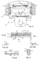
- FIG. 1 is a schematic illustration of a seat belt apparatus showing the belt with the tip assembly thereon holding a baby seat on a rear seat of a vehicle;
- FIG. 1A is an enlargement view of the tip assembly and buckle in the buckled position;
- FIG. 2 is a view illustrating the tip assembly in a locked condition;
- FIG. 3 is a view showing the tip assembly in its unlocked condition;
- FIG. 4 is a plan view of the tip assembly;
- FIG. 5 is an elevational view of an insert having the preferred locking teeth;
- FIG. 5A is a view of a row of locking teeth on the insert taken along the
line 5A-5A in FIG.5; - FIG. 5B is a view of a row of locking teeth on the insert taken along the
line 5B-5B in FIG. 5; - FIG. 6 is an plan view of the insert of FIG. 5; and
- FIG. 7 is a cross-sectional view of a tooth insert body taken along the line 7-7 of FIG. 6.
- As shown in the drawings for purposes of illustration, the invention is embodied in a
seat belt apparatus 12 mounted in a vehicle having arear seat 10, upon which is positioned ababy seat 14. A seat belt is connected at oneend 15 to a seat belt retractor which is located upwardly of the vehicle seat and near a passenger's head and a pillar of the vehicle. The seat belt has atip assembly 28 thereon which can be connected to abuckle 30 which has a typical buckle opening 32 (FIG. 1A) into which a tongue plate ortip 34 on the tip assembly is inserted. Alocking pawl 36 is spring biased to a locking condition and is adapted to ride over thetongue 34 and to snap into locking in theopening 38 and the tongue to thereby latch the tip assembly to the buckle. Arelease button 40 typically further is associated with a buckle to disengage the locking pawl from theopening 38 to release the tip assembly from confined securement with the buckle. - The
locking tip assembly 28 includes an elongated, flat metal plate ortip body 101 the forward end of which is narrowed to form thetip 34 and includes asnubber slide 60 that slides on thetip body 101 between the release position shown in FIG. 3 in which the tip slides freely down the belt and locking position shown in FIG. 2 in which the belt is gripped in a nip between the slide and thetip body 101. That is, in the buckled condition, with the retractor pulling a force upon thebelt portion 42, theslide portion 60 cooperates with a grippingedge 59 on the tip or tongue plate. The belt is inserted through an opening 63 (FIG. 3) in thesnubber slide 60 and an alignedopening 52 in thetip body 101. Additionally, the belt is entrained about aforward edge 72 of the snubber slide which draws the snubber slide upwardly along the tip until thegripping edge 70 on theslide 60 and the facinggrip edge 59 on thetip body 101 tightly squeeze the inner positioned belt. In this belt-gripping position, the tightly-pinchedbelt 42 precludes slippage at predetermined load range conditions. - In the device shown in US-A-4 480 854, the gripping and locking load was about 1334 N (300 pounds); and any force applied beyond that overcame the gripping action and allowed the belt to slip.
- The problem addressed by the present invention is how to increase the gripping or locking force to preclude belt movement through the nip of the belt gripping means at loads in excess of 5337.6 N (1,600 pounds) and yet release the tip assembly for a free-falling movement when the load was released. Initial experiments were made with various configurations which would wedge together and hold against slippage at 5337.6 N (1,600 pound) loads, but the wedged parts could not be separated by the hands of a person trying to pull the pieces apart. In other instances, the application of a 5337.6 N (1,600 pound) load bent the parts permanently from their original shape such that they should not or could not be reused after loading.
- In accordance with the present invention, the free-falling tip assembly has releasable gripping means 71 on the
slide 60 and on thetip body 101 which are movable from the release position of FIG. 3 to the gripping or locking position of FIG. 2 such that a pulling force of 5337.6 N (1,600 pounds) and greater exerted onbelt portion 42 pulling to the right as shown in FIG. 2 is not able to cause the belt to be pulled through the gripping means. Upon release of a 5337.6 N (1,600 pound) load, the slide and tip may be separated manually without the use of tools; and the tip assembly will again slide down the belt and assume the release position, as shown in FIG. 3. This locking of the belt at 5337.6 N (1,600 pound) load is achieved by a gripping means having a first set ofteeth 61 on theslide 60 and a second set ofteeth 35 on thetip body 101 with the respective sets of teeth being onopposite sides small rows 45 ofteeth 61 and are in verysmall rows 46 ofteeth 35. The rows are offset from each other so that the teeth of one row will not hit point-to-point the opposite teeth of the opposing set of teeth. As shown in FIG. 5, theteeth 35 ofrows 46 are located to move into spaces between therows 45 ofteeth 61. - The preferred and illustrated sets of
teeth rows insert body 49 on which the teeth are integrally formed. Also, it is preferred to have a large or wide surface area over which to spread the gripping force being applied to the belt. To this end, the rows of teeth extend laterally substantially across the full width of the belt being gripped. Thus, not all of the load is centered at the middle of the belt as might tear the center of the belt caught in the nip of the opposing sets of teeth. Herein, there are three teeth in each vertical row so that the load is applied not as a straight, thin, pinching line from a single horizontal line of teeth, but is spread over a broader vertical area of three vertically-spaced lines of teeth to thereby distribute the load vertically as well as horizontally across the belt. - The load is also preferably distributed across a large number of very small and very
fine teeth respective insert bodies 49. The insert bodies are mounted in recess orgrooves 55 and 57 (FIG. 3) on thegripping edge 70 of the slide andgripping edge 59 on thetip body 101, respectively. Preferably, the inserts and teeth are made of glass-filled nylon in molded blocks with the teeth molded integrally with the insert body. Herein, theslide 60 is formed of metal rather than plastic as disclosed in the US-A-4 588 207, to be able to withstand the high loads applied thereto without deforming or breaking. The preferred metal for the slide is a die cast body of aluminium or zinc alloy although other metals and means of making the slide could be used to withstand the loads applied. Also, to assure a better grip and biting, the individual teeth have flat upper edges 53 (FIG. 7) and downwardly-slopingsurfaces 54. The preferred teeth are generally triangular in shape and have the sizes and dimensions shown in FIG. 5. Both sets ofteeth insert bodies 49 are identical except theteeth 35 are shifted over one row space on the body for theteeth 63. - Turning now to a more detailed description of the invention, the
tip assembly 28 includes an elongated generally-planar tongue plate or tip frame ortip body 101, which includes a flat steel plate which has a narrow tongue ortip 34 at its forward end with a lockingopening 38. Thetip body 101 has arectangular opening 52 which helps define the belt receiving slot. A pair of stamped ribs 101a (FIG. 4), flanking the lateral sides of the opening and stampedrib 101b along the rear of the slot, give theframe body 101 additional strength. A channel 53a is cutout in theframe body 101 and extends forwardly from the rectangular portion of theopening 52. Adetent 74 on thesnubber slide 60 slides in the channel 53a and its forward end will abut a stoppingsurface 53b at the front end of the channel to hold thesnubber slide 60 against sliding forwardly from thetip frame 101. - To accommodate the
insert body 49 having theteeth 35, which is thicker than the plate of thetip body 101, thetip body 101 is provided with an enlarged rear liner body 106 (FIG. 3) made of metal with achannel 108 for receiving a rear bar portion 56 of thetip body 101 behind the slot opening 52 in thetip body 101. Theliner body 106 has a widefront face 59 facing the belt with theslot 55 therein to receive the teeth insertbody 49. The force transmitted at the time of gripping from thetoothed insert 49 is transmitted through the tapered upper bar portion 56 of theliner body 106 into thetongue plate body 101. Alower portion 102 of theliner body 106 extends into thetongue plate body 101. Alower portion 102 of theliner body 106 extends beneath the tip body bar 56. Thelower tooth 35 is backed by the bar portion 56 because it is the plane defined by thickness of the tongue plate while the upper teeth project above the tonguetip plate body 101. - The snubber slide means 60 is slid ably mounted on the
tip frame 101 prior to thebelt 15 being inserted through theslot 52. Thesnubber slide 60 as best seen in FIG. 4, is a closed, channel-shaped body having a longitudinally-extendingslot 63 defined by four walls including atop wall 66 and abottom wall 68 joined to a pair of short, sidewalls 62 or corner sections. Thetop wall 66 and thebottom wall 68 are generally flat, planar parallelograms. In order to assemble, thetop wall 62 may be made separate from the other three walls and be attached thereto from fasteners after assembly on thetip frame 101. - The load of 5337.6 N (1,600 pounds) or greater is applied to the
snubber slide 60 against itsbottom wall 68 at itsforward edge 72, (FIG. 2) by thebelt portion 42 which exerts a pull, e.g., of 5337.6 N (1,600 pounds) to pull thesnubber slide 60 upwardly and rearwardly to cause both sets ofteeth bottom wall 68 of thesnubber slide 60 comprises a relatively wide bar extending from a transverse,forward edge 72, which abuts the belt when thetip assembly 28 is buckled, as seen in FIG. 2, to a reartransverse edge 71. The forwardtransverse edge 72 of thebottom wall 68 is located forward of theteeth 35 mounted on upperrear edge 70 of thetop wall 66, as clearly shown in FIGS. 2, 3 and 4, so that thesnubber teeth 61 bite intoside 80 of the belt and forceteeth 35 of thestationary tip frame 101 to also bite intoside 81 of thebelt 15. Thebottom wall 68 of thesnubber slide 60 is free to slide underneath the rear portion of thetip frame 101 when the tip is buckled in the manner disclosed in US-A-4 480 854 which is hereby incorporated by reference as if fully reproduced herein. - When the
tip assembly 28 has been-assembled with thebelt 15 fed there through, the belt passes through theframe slot 52 and also throughslot 63 in thesnubber slide 60. As best seen in FIG. 3, the normal weight in balance caused by the heavier lower end of the tip ortongue 34 will cant thetip assembly 28 relative to the vertical belt run 18 as seen in FIG. 3. In this free-falling position of FIG. 3, thesnubber slide 60 has moved forwardly along thetip frame 101 from the belt-gripping position of FIG. 2, and this allows the tip assembly to slide freely with theedges snubber slide 60 and theframe 101, respectively, sliding along the forward and rearward sides 80 and 81 of the belt. The unbuckledtip assembly 28 is thereby free to slide downward along the belt run 18 until stopped by some means, such as astop 75 on the belt. - In order to engage the
tip assembly 28 operatively with thebuckle 30, the occupant merely grasps thetip assembly 28 and moves the same in a lateral direction and slides the tip assembly along thebelt 15 until thetongue 34 is brought to latch with thebuckle 30, feeding out during this effort sufficient belt webbing to define the lap-engaging span ofbelt 42 which will be about the baby seat or about the lap of the person seated where the baby seat would be located. There is also left a shoulder-engagingspan 44 of the belt which will engage a person seated on the rear seat or which will engage the back bench portion of the rear seat. When the tip assembly is engaged with the buckle, the pull of theretractor 26 exerts an upward and rightward force on theforward edge 72 of the tip assembly, as viewed in FIGS. 1 and 2, to lift thesnubber slide 60 in this same direction to the belt-gripping position, as seen in FIG. 2. In this position, thebelt shoulder portion 44 trained about theforward edge 72 of thesnubber slide 60 draws the snubber slide upwardly along thetip frame 101 until the upper grippingportion 70 on thesnubber slide 60 brings itsgripping teeth 61 into engagement with thebelt side 80 facing it and thereafter pushing theother side 81 of the belt into the second set ofteeth 35 on thegrip portion 72 of theframe liner 101, thereby tightly gripping and interlocking theteeth belt 15. In this position, the tightly grippedbelt 15 is precluded from any further withdrawal of the belt webbing in the direction toward the lap-engagingportion 42 with loads up to 5337.6 N (1,600 pounds) which would tend to enlarge the lap-engaging portion. - It has been found that the application of a 5337.6 N (1,600 pound) load that one can grasp manually the
snubber slide 60 and move the snubber slide downwardly to release theteeth 61 from thebelt webbing side 80 and also by pulling on thetip frame 101, one can move itsteeth 35 to release the side belt. Thus, thetip assembly 28 is free for sliding movement along thebelt 15 after such interlocking. - From the foregoing, it will be seen that there has been provided a fully locking, free-falling tip assembly which slides readily upwardly or downwardly along the belt and which, when brought to its locking position, has means which will fully grip and hold the belt against very high loads and which has the strength and ability to not fail under loading as high as 5337.6 N (1,600 pounds) or more. The teeth do not destroy the belt; and the toothed grip on the belt can be removed by the person grasping and pulling apart the
slide 60 and theframe 101 from thebelt 15, and the tip assembly can continue in their usage. The particular configuration allows the belt to slide, and the teeth are situated in a position so that they do not normally abrade the belt during ordinary usage. Thus, the belt will not be abraded and will survive for life or a cycle of time so as to meet standards.
Claims (4)
- A safety belt apparatus, comprising: a safety belt (15) providing shoulder (44) and lap (42) portions, a belt retractor (26) connected to one end of the belt (15) for rewinding and pulling a portion of the belt into a generally vertical orientation when the belt (15) is released for full retraction, a tip assembly (28) slidably mounted on the belt (15), said tip assembly having an opening (63) through which the belt (15) passes, a tongue plate (34) for connection to a buckle (30) and slide means (60) shiftable by the tongue plate (34) hanging downwardly and with the belt (15) in the vertical orientation to allow free sliding of the tip assembly (28) downwardly along the belt (15), the slide means (60) having a first belt engaging face (57) on one side of the opening (63) for gripping one side (80) of the belt (15), a belt liner body (106) on the tongue plate (34), a second belt engaging face (59) on said liner body (106) on an opposite side of the opening for gripping the other side (81) of the belt (15) and a member (68) on said slide means (60) for engaging the belt (15) and being forced by the belt (15) to move the slide means (60) to carry the first belt engaging face (57) into the belt (15) and to force the belt (15) against the second belt engaging face (59) to lock the belt (15) against transfer between lap (42) and shoulder (44) portions, characterised in that a first set of teeth (61) are mounted on the first belt engaging face (57) of the slide means (60) at a position below the side (80) of the belt and spaced from the belt (15) when the side (80) of the belt (15) is engaging a lower corner of the second belt engaging face (59) when the slide means (60) is in an open position for allowinq a free slidina of the tip assembly (28) downwardly along the belt (15); in that a second set of teeth (35) are mounted on the second belt engaging face (59) on the liner body (106) at a position above the side (81) of the belt (15) is engaging an upper corner of the second belt engaging face (59) on the liner body (106) when the slide means (60) is in an open position for allowinq a free sliding of the tip assembly (28) downwardly along the belt (15); and in that the member (68) on the slide means (60) is a rigid, non-deflectable bar of metal having a forward edge (72) for engaging the belt beneath tongue plate (34) and liner body (106) to be moved by the belt and thereby to lift the first set of teeth (61) on the slide means (60) to abut said one belt side (80) and to push the other belt side (81) into the second set of teeth (35) on said liner body (106) to grip the belt tightly against slipping with the application of predetermined high loads of force on the belt (15).
- A system in accordance with Claim 1, characterised in that the first and second set of teeth (61, 35) are in a series of tows of fine teeth, the rows of teeth on the tongue plate and on the slide means being offset from each other.
- An apparatus in accordance with Claim 2, characterised in that the teeth (35, 61) are aligned in rows oblique to the direction of the longitudinal axis of the belt being gripped between the first and second sets of teeth.
- An apparatus in accordance with Claim 1, characterised in that said first set of teeth (35) is provided on an insert (49) formed from another material and mounted in said metal body (60) at the opening (63) to bite into and to grip the belt.
Applications Claiming Priority (2)
| Application Number | Priority Date | Filing Date | Title |
|---|---|---|---|
| US441308 | 1989-11-27 | ||
| US07/441,308 US4979764A (en) | 1989-11-27 | 1989-11-27 | Free-falling tip with full locking |
Publications (2)
| Publication Number | Publication Date |
|---|---|
| EP0430522A1 EP0430522A1 (en) | 1991-06-05 |
| EP0430522B1 true EP0430522B1 (en) | 1994-06-22 |
Family
ID=23752387
Family Applications (1)
| Application Number | Title | Priority Date | Filing Date |
|---|---|---|---|
| EP90312561A Expired - Lifetime EP0430522B1 (en) | 1989-11-27 | 1990-11-19 | Free-falling tip with full locking |
Country Status (6)
| Country | Link |
|---|---|
| US (1) | US4979764A (en) |
| EP (1) | EP0430522B1 (en) |
| JP (1) | JPH03227755A (en) |
| KR (1) | KR910009509A (en) |
| CA (1) | CA2030924A1 (en) |
| DE (1) | DE69010159T2 (en) |
Families Citing this family (13)
| Publication number | Priority date | Publication date | Assignee | Title |
|---|---|---|---|---|
| US5417455A (en) * | 1989-11-27 | 1995-05-23 | Takata Inc. | Free-falling tip with full locking |
| US5100176A (en) * | 1991-05-10 | 1992-03-31 | Trw Vehicle Safety Systems Inc. | Tongue assembly |
| US5138749A (en) * | 1991-08-13 | 1992-08-18 | Trw Vehicle Safety Systems Inc. | Tongue assembly |
| JPH05154008A (en) * | 1991-12-06 | 1993-06-22 | Takata Kk | Tongue assembly of seat belt |
| US5590907A (en) * | 1995-10-10 | 1997-01-07 | Vehicle Safety Systems, Inc. | Seat belt positioning device and system |
| US8087696B2 (en) * | 2007-06-11 | 2012-01-03 | Lap Belt Cinch, Inc. | Vehicle occupant restraint and method |
| US8840145B2 (en) * | 2012-06-21 | 2014-09-23 | Tk Holdings Inc. | Seat belt system with rollover locking tongue |
| DE102012022278A1 (en) * | 2012-11-14 | 2014-05-15 | Volkswagen Aktiengesellschaft | Seat belt device in a vehicle |
| DE102013216326A1 (en) * | 2013-08-16 | 2015-02-19 | Volkswagen Aktiengesellschaft | Seat belt device in a vehicle |
| US10512309B2 (en) | 2018-01-11 | 2019-12-24 | Ford Global Technologies, Llc | Seat belt connector tongue assembly having locking mechanism |
| US10543806B2 (en) * | 2018-02-27 | 2020-01-28 | Ford Global Technologies, Llc | Seatbelt assembly |
| DE102018220620B4 (en) * | 2018-11-29 | 2022-10-13 | Joyson Safety Systems Germany Gmbh | Belt deflection device |
| SG10201907758XA (en) * | 2019-08-22 | 2021-03-30 | Green 5 Holding Pte Ltd | A self-releasable safety belt |
Family Cites Families (45)
| Publication number | Priority date | Publication date | Assignee | Title |
|---|---|---|---|---|
| US706080A (en) * | 1901-03-19 | 1902-08-05 | George B Mevis | Buckle. |
| US2377287A (en) * | 1942-06-08 | 1945-05-29 | Parva Products Co | Buckle |
| US2938254A (en) * | 1958-11-10 | 1960-05-31 | Koch & Sons Inc H | Webbing adapter |
| US3289261A (en) * | 1964-09-08 | 1966-12-06 | Frank L Davis | Buckle with swinging clamp belt adjustment |
| BE690357A (en) * | 1965-12-17 | 1967-05-02 | ||
| US3439932A (en) * | 1967-04-21 | 1969-04-22 | Robbins Seat Belt Co | Belt retracting device with pendulum actuated locking means |
| US3442529A (en) * | 1967-04-24 | 1969-05-06 | Robbins Seat Belt Co | Inertia retracting device with weight actuated take-up |
| US3414947A (en) * | 1967-07-03 | 1968-12-10 | Holmberg Gote Eskil Yngve | Strap fasteners |
| US3551961A (en) * | 1967-10-18 | 1971-01-05 | Industrifjadrar Ab | Devices for locking a strap cooperating with a retracting mechanism |
| US3588173A (en) * | 1969-01-09 | 1971-06-28 | Edward W Apri | Momentum-actuated harness |
| US3592507A (en) * | 1969-08-15 | 1971-07-13 | Gen Motors Corp | Restraint belt lock |
| DE2047706C3 (en) * | 1970-09-28 | 1979-01-25 | Wolf-Dieter 7071 Lindach Klink | Seat belts for vehicle occupants |
| US3913977A (en) * | 1973-02-16 | 1975-10-21 | Takata Kojyo Co | Automatic locking belt supported retractor |
| US3847434A (en) * | 1973-05-02 | 1974-11-12 | Sigmatex Ag | Vehicle occupant restraint system |
| US4069554A (en) * | 1973-05-11 | 1978-01-24 | Klippan Gmbh Hamburg | Adjustable fitting for safety belt |
| FR2253393A5 (en) * | 1973-12-03 | 1975-06-27 | Peugeot & Renault | |
| SE387242B (en) * | 1974-02-27 | 1976-09-06 | Stece Ab Ind | BAND ADJUSTMENT DEVICE |
| US3888541A (en) * | 1974-07-01 | 1975-06-10 | Allied Chem | Belt locking assembly for safety belt buckle |
| FR2329480A1 (en) * | 1974-07-04 | 1977-05-27 | Bosredon Pierre De | IMPROVEMENT IN THE MOUNTING OF SEAT BELTS USED ESPECIALLY IN MOTOR VEHICLES |
| US3928895A (en) * | 1974-08-19 | 1975-12-30 | Repa Feinstanzwerk Gmbh | Adjustable strap fastener |
| US3941419A (en) * | 1974-11-21 | 1976-03-02 | General Motors Corporation | Buckle component for a vehicle occupant restraint belt system |
| US3981535A (en) * | 1975-05-27 | 1976-09-21 | American Safety Equipment Corporation | Single retractor continuous loop restraint system |
| US3974546A (en) * | 1975-10-02 | 1976-08-17 | The Firestone Tire & Rubber Company | Continuous loop slip tongue |
| JPS5546176Y2 (en) * | 1976-12-13 | 1980-10-29 | ||
| US4211432A (en) * | 1977-12-28 | 1980-07-08 | Toyota Jidosha Kogyo Kabushiki Kaisha | Webbing guide |
| US4184234A (en) * | 1978-09-18 | 1980-01-22 | Indiana Mills & Manufacturing Inc. | Anti-creep seat belt buckle and tongue combination |
| JPS5636356U (en) * | 1979-08-31 | 1981-04-08 | ||
| FR2475905B1 (en) * | 1980-01-11 | 1987-02-13 | Alix Maurice | TENSION STOP FOR SEAT BELT OF THE WINDING TYPE |
| US4310175A (en) * | 1980-02-19 | 1982-01-12 | Allied Corporation | Belt clamping apparatus with self-aligning feature |
| US4315637A (en) * | 1980-03-24 | 1982-02-16 | Allied Corporation | Seat belt web guide |
| DE3021387C2 (en) * | 1980-06-06 | 1983-09-01 | Daimler-Benz Ag, 7000 Stuttgart | Lock tongue for seat belts |
| US4386452A (en) * | 1980-07-07 | 1983-06-07 | Allied Corporation | Adjustable self-locking tongue plate for seat belts |
| US4364584A (en) * | 1981-04-15 | 1982-12-21 | General Motors Corporation | Junction ring for continuous-loop passive seat belt system |
| US4452469A (en) * | 1982-02-16 | 1984-06-05 | General Motors Corporation | Seat belt junction ring |
| DE3216075A1 (en) * | 1982-04-30 | 1983-11-03 | Eisen-und Drahtwerk Erlau AG, 7080 Aalen | Adjusting device for belts, preferably for lap belts |
| US4464811A (en) * | 1982-09-16 | 1984-08-14 | Aeroquip Corporation | Over center strap buckle |
| US4480854A (en) * | 1982-11-08 | 1984-11-06 | Gateway Industries, Inc. | Free-falling, self-locking adjustable tip assembly |
| US4588207A (en) * | 1982-11-08 | 1986-05-13 | Gateway Industries, Inc. | Free-falling, self-locking adjustable tip assembly |
| US4525901A (en) * | 1983-11-23 | 1985-07-02 | American Cord & Webbing Co., Inc. | Buckle having improved web securement |
| US4551889A (en) * | 1984-11-21 | 1985-11-12 | Allied Corporation | Low friction self-locking adjust tongue |
| JPS61111304U (en) * | 1984-12-26 | 1986-07-14 | ||
| DE3519322A1 (en) * | 1985-05-30 | 1986-12-04 | TRW Repa GmbH, 7077 Alfdorf | DEVICE FOR FASTENING A CHILD SEAT ON A VEHICLE SEAT BY MEANS OF A NORMAL THREE-POINT AUTOMATIC SAFETY BELT SYSTEM |
| US4608735A (en) * | 1985-08-15 | 1986-09-02 | Nippon Notion Kogyo Co., Ltd. | Sliding bar buckle |
| GB8710465D0 (en) * | 1987-05-01 | 1987-06-03 | Ase Uk Ltd | Vehicle seat belt retractor |
| US4871190A (en) * | 1987-10-08 | 1989-10-03 | Trw Vehicle Saftey Systems Inc. | Safety apparatus |
-
1989
- 1989-11-27 US US07/441,308 patent/US4979764A/en not_active Expired - Lifetime
-
1990
- 1990-11-19 DE DE69010159T patent/DE69010159T2/en not_active Expired - Fee Related
- 1990-11-19 EP EP90312561A patent/EP0430522B1/en not_active Expired - Lifetime
- 1990-11-26 KR KR1019900019197A patent/KR910009509A/en not_active Ceased
- 1990-11-27 JP JP2325132A patent/JPH03227755A/en active Pending
- 1990-11-27 CA CA002030924A patent/CA2030924A1/en not_active Abandoned
Also Published As
| Publication number | Publication date |
|---|---|
| JPH03227755A (en) | 1991-10-08 |
| EP0430522A1 (en) | 1991-06-05 |
| DE69010159D1 (en) | 1994-07-28 |
| DE69010159T2 (en) | 1994-10-06 |
| CA2030924A1 (en) | 1991-05-28 |
| KR910009509A (en) | 1991-06-28 |
| US4979764A (en) | 1990-12-25 |
Similar Documents
| Publication | Publication Date | Title |
|---|---|---|
| US5417455A (en) | Free-falling tip with full locking | |
| US4979764A (en) | Free-falling tip with full locking | |
| US5292181A (en) | Anti-cinch and anti-chafe seat belt system | |
| US7278684B2 (en) | Retractable coupling apparatus | |
| US5088160A (en) | Lap belt webbing adjuster | |
| US6312015B1 (en) | Clamp for retractor belt | |
| US4848794A (en) | Free running cinching connector | |
| US7073235B2 (en) | Non-inertial release safety restraint belt buckle systems | |
| US9022483B2 (en) | Seatbelt buckle tongue assembly | |
| EP0043430B1 (en) | Adjustable self-locking tongue plate for seat belt | |
| US4470618A (en) | Adjustable seat belt anchorage | |
| EP0181123B1 (en) | Free-falling, self-locking adjustable tip assembly | |
| EP0113173B1 (en) | Free-falling, self-locking adjustable tip assembly | |
| US4962572A (en) | Tongue assembly | |
| US5328249A (en) | Seat belt system | |
| US3981535A (en) | Single retractor continuous loop restraint system | |
| US5794977A (en) | D-ring height adjuster | |
| US7263749B2 (en) | Non-inertial release safety restraint belt buckle system | |
| EP0233052B1 (en) | Harness with strap length adjustment device | |
| US4552408A (en) | Adjustable anchor mounting device | |
| US7225511B2 (en) | Non-inertial release safety restraint belt buckle system | |
| EP3715187A1 (en) | Multi-point seat belt system | |
| GB2073810A (en) | Improvements in or relating to a buckle | |
| USRE26754E (en) | Safety belt buckle | |
| US3453699A (en) | Safety belt assembly |
Legal Events
| Date | Code | Title | Description |
|---|---|---|---|
| PUAI | Public reference made under article 153(3) epc to a published international application that has entered the european phase |
Free format text: ORIGINAL CODE: 0009012 |
|
| AK | Designated contracting states |
Kind code of ref document: A1 Designated state(s): DE FR GB SE |
|
| 17P | Request for examination filed |
Effective date: 19910522 |
|
| 17Q | First examination report despatched |
Effective date: 19920803 |
|
| GRAA | (expected) grant |
Free format text: ORIGINAL CODE: 0009210 |
|
| AK | Designated contracting states |
Kind code of ref document: B1 Designated state(s): DE FR GB SE |
|
| REF | Corresponds to: |
Ref document number: 69010159 Country of ref document: DE Date of ref document: 19940728 |
|
| ET | Fr: translation filed | ||
| PG25 | Lapsed in a contracting state [announced via postgrant information from national office to epo] |
Ref country code: SE Effective date: 19940922 |
|
| PLBE | No opposition filed within time limit |
Free format text: ORIGINAL CODE: 0009261 |
|
| STAA | Information on the status of an ep patent application or granted ep patent |
Free format text: STATUS: NO OPPOSITION FILED WITHIN TIME LIMIT |
|
| 26N | No opposition filed | ||
| PGFP | Annual fee paid to national office [announced via postgrant information from national office to epo] |
Ref country code: FR Payment date: 19951110 Year of fee payment: 6 |
|
| PGFP | Annual fee paid to national office [announced via postgrant information from national office to epo] |
Ref country code: GB Payment date: 19951117 Year of fee payment: 6 |
|
| PG25 | Lapsed in a contracting state [announced via postgrant information from national office to epo] |
Ref country code: GB Effective date: 19961119 |
|
| K1C1 | Correction of patent application (title page) published |
Effective date: 19910605 |
|
| GBPC | Gb: european patent ceased through non-payment of renewal fee |
Effective date: 19961119 |
|
| PG25 | Lapsed in a contracting state [announced via postgrant information from national office to epo] |
Ref country code: FR Effective date: 19970731 |
|
| REG | Reference to a national code |
Ref country code: FR Ref legal event code: ST |
|
| PGFP | Annual fee paid to national office [announced via postgrant information from national office to epo] |
Ref country code: DE Payment date: 19971128 Year of fee payment: 8 |
|
| PG25 | Lapsed in a contracting state [announced via postgrant information from national office to epo] |
Ref country code: DE Free format text: LAPSE BECAUSE OF NON-PAYMENT OF DUE FEES Effective date: 19990901 |