EP0430007B1 - A mechanical control device for an electric switch - Google Patents
A mechanical control device for an electric switch Download PDFInfo
- Publication number
- EP0430007B1 EP0430007B1 EP90122056A EP90122056A EP0430007B1 EP 0430007 B1 EP0430007 B1 EP 0430007B1 EP 90122056 A EP90122056 A EP 90122056A EP 90122056 A EP90122056 A EP 90122056A EP 0430007 B1 EP0430007 B1 EP 0430007B1
- Authority
- EP
- European Patent Office
- Prior art keywords
- switch
- housing
- lever
- slider
- working position
- Prior art date
- Legal status (The legal status is an assumption and is not a legal conclusion. Google has not performed a legal analysis and makes no representation as to the accuracy of the status listed.)
- Expired - Lifetime
Links
Images

Classifications
-
- H—ELECTRICITY
- H01—ELECTRIC ELEMENTS
- H01H—ELECTRIC SWITCHES; RELAYS; SELECTORS; EMERGENCY PROTECTIVE DEVICES
- H01H9/00—Details of switching devices, not covered by groups H01H1/00 - H01H7/00
- H01H9/20—Interlocking, locking, or latching mechanisms
-
- H—ELECTRICITY
- H01—ELECTRIC ELEMENTS
- H01R—ELECTRICALLY-CONDUCTIVE CONNECTIONS; STRUCTURAL ASSOCIATIONS OF A PLURALITY OF MUTUALLY-INSULATED ELECTRICAL CONNECTING ELEMENTS; COUPLING DEVICES; CURRENT COLLECTORS
- H01R13/00—Details of coupling devices of the kinds covered by groups H01R12/70 or H01R24/00 - H01R33/00
- H01R13/66—Structural association with built-in electrical component
- H01R13/70—Structural association with built-in electrical component with built-in switch
- H01R13/707—Structural association with built-in electrical component with built-in switch interlocked with contact members or counterpart
-
- H—ELECTRICITY
- H01—ELECTRIC ELEMENTS
- H01H—ELECTRIC SWITCHES; RELAYS; SELECTORS; EMERGENCY PROTECTIVE DEVICES
- H01H71/00—Details of the protective switches or relays covered by groups H01H73/00 - H01H83/00
- H01H71/02—Housings; Casings; Bases; Mountings
- H01H71/0264—Mountings or coverplates for complete assembled circuit breakers, e.g. snap mounting in panel
- H01H71/0271—Mounting several complete assembled circuit breakers together
- H01H2071/0278—Mounting several complete assembled circuit breakers together with at least one of juxtaposed casings dedicated to an auxiliary device, e.g. for undervoltage or shunt trip
-
- H—ELECTRICITY
- H01—ELECTRIC ELEMENTS
- H01H—ELECTRIC SWITCHES; RELAYS; SELECTORS; EMERGENCY PROTECTIVE DEVICES
- H01H71/00—Details of the protective switches or relays covered by groups H01H73/00 - H01H83/00
- H01H71/10—Operating or release mechanisms
- H01H71/1009—Interconnected mechanisms
Definitions
- This invention relates to a mechanical control device for an electric switch.
- a problem to be solved with electric systems is sometimes that of linking the set/release functions of an electric switch to the positions of some ancillary equipment; for instance, the ability to set the switch may be subordinate to an electric plug being plugged in, a door being shut, a handle moved to a certain position, etc.
- a frequently occurring problem is that of linking the position of some ancillary equipment to the set/released condition of a switch; for instance, with the switch in the set position, it may be necessary to prevent mechanically an electric plug from being plugged in/out, a door from being opened, a handle from being moved, etc.
- the object that underlies this invention is to provide a mechanical control device for an electric switch, which can solve the above problems in a consistent manner with the requirement for exchangeability of today's modular systems.
- a mechanical control device for an electric switch specifically an automatic electric switch of modular design having a front-mounted bistable set/release lever and a side-mounted setting inhibit/assent slider accessible through a slot
- a mechanical control device for an electric switch specifically an automatic electric switch of modular design having a front-mounted bistable set/release lever and a side-mounted setting inhibit/assent slider accessible through a slot
- a mechanical control device for an electric switch specifically an automatic electric switch of modular design having a front-mounted bistable set/release lever and a side-mounted setting inhibit/assent slider accessible through a slot
- a mechanical control device for an electric switch specifically an automatic electric switch of modular design having a front-mounted bistable set/release lever and a side-mounted setting inhibit/assent slider accessible through a slot
- a mechanical control device for an electric switch specifically an automatic electric switch of modular design having a front-mounted bistable set/release lever and a side-mounted setting inhibit/assent slider accessible through a slot
- a release member within said housing provided with
- Such a device can achieve the object outlined hereinabove in that it contains, within a modular design structure similar to that of the switch, elements which can function in combination as a mechanical interface between plural ancillary mechanical members (such as plugs, doors, handles, etc.) and the switch to be controlled.
- ancillary mechanical members such as plugs, doors, handles, etc.
- the device includes a pushbutton projecting forwardly from the housing and being associated mechanically with the pressure member such that the pressure member will occupy its working position as the pushbutton is held depressed.
- the switch cannot be set because its side slider will be held in the inhibit position by the peg of the release member.
- Said pushbutton is suited, in particular, to control the positioning of a door: the door will only be pushing in the pushbutton when closed to thereby enable the switch to be set.
- this device includes two separate pressure members, arranged to act separately on the release member. In this way, the ability to set the switch can be interlocked with the positions of two different mechanical members.
- This device also includes, to advantage, an actuator movable in a guided fashion within the housing between a home or rest position and a working or operative position, by operation of external mechanical members, a front-mounted bistable lever on the housing similar to that on the switch and associated rigidly with the last-mentioned lever by means of a crosspiece, and mechanical linkage means within the housing, between the actuator and the bistable lever, whereby the actuator will either occupy its home position or its working position according to whether the bistable lever of the switch is in the set or the release position.
- an actuator movable in a guided fashion within the housing between a home or rest position and a working or operative position, by operation of external mechanical members
- a front-mounted bistable lever on the housing similar to that on the switch and associated rigidly with the last-mentioned lever by means of a crosspiece
- mechanical linkage means within the housing, between the actuator and the bistable lever, whereby the actuator will either occupy its home position or its working position according to whether the bistable lever of the switch
- the switch I is a modular design, automatic electric switch having a front-mounted, bistable set/release lever L and a side-mounted, setting inhibit/assent slider (not shown in the drawings) which is accessible through a slot A.
- the device 1 comprises a housing 3 having similar shape and dimensions to the switch I.
- the housing 3 has a recess 4 on its rear for attachment to a mounting bracket in a manner known per se.
- the device 1 also comprises, mounted within the housing 3, a release member 5 which has freedom of movement between a rest or home position (shown in full lines, Figure 1) and a working or operative position (shown in dash lines, Figure 1); the release member 5 comprises preferably a lever 6 pivoted on the housing 3 by means of a pivot 7.
- the release member 5 is provided with a peg 8, mounted on the remote end of the lever 6 from the pivot 7 to jut out sideways; the peg 8 protrudes sideways out of the housing 3 through a slot 15.
- the slot 15 would be facing the corresponding slot in the switch I through which the peg 8 engages with the side-mounted, switch setting inhibit/assent slider; specifically, with the release member 5 in its home position, the slider will be in the position inhibiting the setting of the switch I, whereas with the release member 5 in its working position, the slider will be in the position of assent to the setting of the switch I.
- the device 1 comprises at least one pressure member inside the housing 3, preferably two pressure members 20 and 21, independent of each other.
- Each of these members is movable in a guided fashion within the housing 3 from a home or rest position (shown in full lines, Figure 1) to a working or operative position (shown in dash lines, Figure 1) against the bias of respective springs 22 and 23; when in the home position, each pressure member 20 and 21 holds, independently of the other, the release member 5 in its home position (which, as mentioned, reflects in disability to set the switch I), whereas in the working position, each of the pressure members 20 and 21 allows the release member 5 to move into its working position (which, as mentioned, reflects in assent to the setting of the switch I).
- the pressure member 20 comprises two arms 24 and 26 so made rigid together as to form a crank lever pivoted on the housing 3 by means of a pivot 28.
- the arm 26 is in contact engagement with a branch 30 of the lever 6 of the release member 5; the arm 24 is arranged to push the spring 22 against a seat 32 formed in the housing 3.
- a member (not shown) to be operated from without the housing 3 to drive the pressure member by pushing the arm 24 against the spring 22; this member may vary contingent on individual requirements: as an example, it may be a rotary shaft or a slider.
- the pressure member 21 comprises two arms 25 and 27 made unitary with each other into a crank lever pivoted on the housing 3 by means of a pivot 29.
- the arm 27 is in contact engagement with a branch 31 of the lever 6 of the release member 5; the arm 25 engages in link-motion relationship with a pushbutton 40 which fits slidably in a respective seat 41 formed in the housing 3, on the front portion thereof, such that the pushbutton 40 will project from the housing 3.
- the spring 23 is received at the bottom of the seat 41 and will be compressed on depressing the pushbutton 40.
- the device 1 further comprises an actuator 50, in the form of a slide movable in a guided fashion within a respective seat 51 formed in the housing 3, between home and working positions as external mechanical members (not shown in the drawings) are operated which may be, for example, a latch mechanism for locking an electric plug in a tap.
- actuator 50 in the form of a slide movable in a guided fashion within a respective seat 51 formed in the housing 3, between home and working positions as external mechanical members (not shown in the drawings) are operated which may be, for example, a latch mechanism for locking an electric plug in a tap.
- a bistable lever 53 similar to the lever L of the switch I, is provided on the front of the housing 3; the lever 53 is mounted on a drum 54 journalled within the housing 3 and rigidly associated with the lever L of the switch I by means of a crosspiece 55.
- a mechanical linkage arrangement whereby the actuator 50 will either occupy its home position or working position, according to whether the bistable lever L of the switch I was in its set or release position.
- This arrangement comprises a rocker arm 56 and a connecting rod 58; the rocker arm 56 is pivoted on the housing 3 by means of a center pivot 57, and engages on the one side with the actuator (a in link-motion relationship, and is pivoted on the other side to the connecting rod 58; the connecting rod 58, besides being pivoted to the rocker arm 56, is connected pivotally to the drum 54 as well, on the remote end thereof from the lever 53.
- This device 1 operates as follows.
- the components of the device 1 will occupy their respective home positions shown in full lines in Figure 1.
- the springs 22 and 23 are urging the pressure members 20 and 21 so to act on the release member 5 as to hold it in its home position; as a result, the peg 8 will hold the side-mounted, switch I setting inhibit/assent slider in the inhibit position.
- the actuator 50 will also occupy its home position (which corresponds with the positioning of the external members driven by the actuator sought under the rest condition).
- pressure member 20 or 21, e.g. member 20 is acted upon (by performing the action contemplated for that pressure member, such as the plugging in of an electric plug), the pressure member 20 shall move to its working position, indicated by broken lines in Figure 1; however, this would not yet enable the switch I to be set because the release member 5 is still held in the home position by the other pressure member 21, thereby the side slider of the switch I is still in the inhibit position.
- the modular design housing 3 affords utmost simplicity of installation in modular electric systems, while not only retaining all the advantages of modularity for the system, but also transferring such advantages to the mechanical control function; in particular, while the device 1 described and illustrated by way of example in the foregoing as equipped with two pressure members and one actuator, contingent on specific demands, a mechanical control device may be employed which includes a different number of pressure members and/or actuators.
- a device of this type can be readily replaced either on the occurrence of damages or in the event that changed requirements for the electric system call for a more complex device.
Landscapes
- Push-Button Switches (AREA)
- Switch Cases, Indication, And Locking (AREA)
- Mechanisms For Operating Contacts (AREA)
Description
- This invention relates to a mechanical control device for an electric switch.
- A problem to be solved with electric systems is sometimes that of linking the set/release functions of an electric switch to the positions of some ancillary equipment; for instance, the ability to set the switch may be subordinate to an electric plug being plugged in, a door being shut, a handle moved to a certain position, etc.
- Conversely, a frequently occurring problem is that of linking the position of some ancillary equipment to the set/released condition of a switch; for instance, with the switch in the set position, it may be necessary to prevent mechanically an electric plug from being plugged in/out, a door from being opened, a handle from being moved, etc.
- There are examples of prior solutions to the above-outlined problems for specific applications (e.g. interlocked industrial sockets of the CEE-17 type) which take into account the peculiar design of both the switch and its set/release parts, and of the ancillary equipment affected each time. However, such specific approaches hardly suit a situation of ever-increasing acceptance of modular elements, as far as feasible repetitive, exchangeable, and interfitting one another.
- The object that underlies this invention is to provide a mechanical control device for an electric switch, which can solve the above problems in a consistent manner with the requirement for exchangeability of today's modular systems.
- This object is achieved, according to the invention, by a mechanical control device for an electric switch, specifically an automatic electric switch of modular design having a front-mounted bistable set/release lever and a side-mounted setting inhibit/assent slider accessible through a slot, characterized in that it comprises a housing with a modular design similar to that of the switch and adapted to be assembled laterally of the switch, a release member within said housing provided with a peg protruding sideways from the housing and being adapted to engage with the inhibit/assent side slider of the switch, said release member being free to move between a home position where the peg holds the switch slider in a setting inhibit position and a working position where the peg holds the switch slider in a setting assent position, at least one pressure member movable in a guided fashion within said housing against the bias of a spring means from a home position where the pressure member holds the release member in its home position to a working position where the pressure member allows the release member to move to its working position.
- Such a device can achieve the object outlined hereinabove in that it contains, within a modular design structure similar to that of the switch, elements which can function in combination as a mechanical interface between plural ancillary mechanical members (such as plugs, doors, handles, etc.) and the switch to be controlled.
- In a preferred embodiment, the device includes a pushbutton projecting forwardly from the housing and being associated mechanically with the pressure member such that the pressure member will occupy its working position as the pushbutton is held depressed. Thus, with no pressure being exerted on the pushbutton, the switch cannot be set because its side slider will be held in the inhibit position by the peg of the release member. Said pushbutton is suited, in particular, to control the positioning of a door: the door will only be pushing in the pushbutton when closed to thereby enable the switch to be set.
- Advantageously, this device includes two separate pressure members, arranged to act separately on the release member. In this way, the ability to set the switch can be interlocked with the positions of two different mechanical members.
- This device also includes, to advantage, an actuator movable in a guided fashion within the housing between a home or rest position and a working or operative position, by operation of external mechanical members, a front-mounted bistable lever on the housing similar to that on the switch and associated rigidly with the last-mentioned lever by means of a crosspiece, and mechanical linkage means within the housing, between the actuator and the bistable lever, whereby the actuator will either occupy its home position or its working position according to whether the bistable lever of the switch is in the set or the release position. Thus, it becomes possible to operate external mechanical members in accord with the set or the release position of the switch.
- Further features and advantages of a device according to the invention will be more clearly understood from the following detailed description of a preferred embodiment thereof, to be taken in conjunction with the accompanying drawings.
- In the drawings:
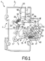
- Figure 1 is a side view of a device according to the invention, with a side wall removed to expose its interior; and
- Figure 2 is a perspective view of the device in Figure 1, shown combined with a modular design automatic switch.
- Generally shown at 1 in the drawings is a mechanical control device for a switch I. The switch I is a modular design, automatic electric switch having a front-mounted, bistable set/release lever L and a side-mounted, setting inhibit/assent slider (not shown in the drawings) which is accessible through a slot A.
- The device 1 comprises a housing 3 having similar shape and dimensions to the switch I. In particular, the housing 3 has a
recess 4 on its rear for attachment to a mounting bracket in a manner known per se. - The device 1 also comprises, mounted within the housing 3, a release member 5 which has freedom of movement between a rest or home position (shown in full lines, Figure 1) and a working or operative position (shown in dash lines, Figure 1); the release member 5 comprises preferably a lever 6 pivoted on the housing 3 by means of a pivot 7.
- The release member 5 is provided with a
peg 8, mounted on the remote end of the lever 6 from the pivot 7 to jut out sideways; thepeg 8 protrudes sideways out of the housing 3 through aslot 15. In normal use of the device 1 in combination with the switch I, theslot 15 would be facing the corresponding slot in the switch I through which thepeg 8 engages with the side-mounted, switch setting inhibit/assent slider; specifically, with the release member 5 in its home position, the slider will be in the position inhibiting the setting of the switch I, whereas with the release member 5 in its working position, the slider will be in the position of assent to the setting of the switch I. - In addition, the device 1 comprises at least one pressure member inside the housing 3, preferably two
pressure members respective springs pressure member pressure members - More specifically, the
pressure member 20 comprises twoarms pivot 28. Thearm 26 is in contact engagement with abranch 30 of the lever 6 of the release member 5; thearm 24 is arranged to push thespring 22 against aseat 32 formed in the housing 3. With thearms 24 and/or 26 of thepressure member 20 there may be associated a member (not shown) to be operated from without the housing 3 to drive the pressure member by pushing thearm 24 against thespring 22; this member may vary contingent on individual requirements: as an example, it may be a rotary shaft or a slider. - The
pressure member 21 comprises two arms 25 and 27 made unitary with each other into a crank lever pivoted on the housing 3 by means of a pivot 29. The arm 27 is in contact engagement with a branch 31 of the lever 6 of the release member 5; the arm 25 engages in link-motion relationship with apushbutton 40 which fits slidably in arespective seat 41 formed in the housing 3, on the front portion thereof, such that thepushbutton 40 will project from the housing 3. Thespring 23 is received at the bottom of theseat 41 and will be compressed on depressing thepushbutton 40. - The device 1 further comprises an
actuator 50, in the form of a slide movable in a guided fashion within arespective seat 51 formed in the housing 3, between home and working positions as external mechanical members (not shown in the drawings) are operated which may be, for example, a latch mechanism for locking an electric plug in a tap. Abistable lever 53, similar to the lever L of the switch I, is provided on the front of the housing 3; thelever 53 is mounted on adrum 54 journalled within the housing 3 and rigidly associated with the lever L of the switch I by means of acrosspiece 55. - Provided inside the housing 3 between the
actuator 50 and thebistable lever 53 is a mechanical linkage arrangement whereby theactuator 50 will either occupy its home position or working position, according to whether the bistable lever L of the switch I was in its set or release position. This arrangement comprises arocker arm 56 and a connectingrod 58; therocker arm 56 is pivoted on the housing 3 by means of acenter pivot 57, and engages on the one side with the actuator (a in link-motion relationship, and is pivoted on the other side to the connectingrod 58; the connectingrod 58, besides being pivoted to therocker arm 56, is connected pivotally to thedrum 54 as well, on the remote end thereof from thelever 53. - This device 1 operates as follows.
- In the rest condition with the switch I in its release position and no mechanical action applied to the
pressure member 20 and thepushbutton 40, the components of the device 1 will occupy their respective home positions shown in full lines in Figure 1. In particular, thesprings pressure members peg 8 will hold the side-mounted, switch I setting inhibit/assent slider in the inhibit position. Further, theactuator 50 will also occupy its home position (which corresponds with the positioning of the external members driven by the actuator sought under the rest condition). - In this rest condition, the switch I cannot be set because the side-mounted slider is in the inhibit position; actually, the lever L may be moved to the setting position, but not held there, and anyhow, would make no electric contact.
- As either pressure member, 20 or 21,
e.g. member 20, is acted upon (by performing the action contemplated for that pressure member, such as the plugging in of an electric plug), thepressure member 20 shall move to its working position, indicated by broken lines in Figure 1; however, this would not yet enable the switch I to be set because the release member 5 is still held in the home position by theother pressure member 21, thereby the side slider of the switch I is still in the inhibit position. - By acting simultaneously on both
pressure members 20 and 21 (that is performing the action contemplated for thepressure member 20 while holding thepushbutton 40 depressed), thepressure members actuator 50 is also brought to its working position (resulting in the desired mechanical action, such as the locking of an electric plug in a tap by means of a latch). The device 1 is now operative. - In this operative condition, the mechanical action disallowed by the positioning of the actuator 50 (such as pulling an electric plug off its tap) could not be performed.
- If in this operative condition just one of the actions on the pressure members, 20 or 21, is wanting (because the action contemplated for the
pressure member 20 or the pressure on thepushbutton 40 is discontinued), the release member 5 is returned to its home position by the action of thespring 22 and/or 23. Consequently, the side slider of the switch I will be moved to the inhibit position, thereby the switch I itself is immediately released. - Thus, the desired function of mechanical control of the switch I is ensured with the intermediary of the device 1. The modular design housing 3 affords utmost simplicity of installation in modular electric systems, while not only retaining all the advantages of modularity for the system, but also transferring such advantages to the mechanical control function; in particular, while the device 1 described and illustrated by way of example in the foregoing as equipped with two pressure members and one actuator, contingent on specific demands, a mechanical control device may be employed which includes a different number of pressure members and/or actuators. In addition, a device of this type can be readily replaced either on the occurrence of damages or in the event that changed requirements for the electric system call for a more complex device.
Claims (4)
- A mechanical control device (1) for an electric switch, specifically an automatic electric switch (I) of modular design having a front-mounted bistable set/release lever (L) and a side-mounted setting inhibit/assent slider accessible through a slot (A), characterized in that it comprises a housing (3) with a modular design similar to that of the switch (I) and adapted to be assembled laterally of the switch (I), a release member (5) within said housing (3) provided with a peg (8) protruding sideways from the housing (3) and being adapted to engage with the inhibit/assent side slider of the switch (I), said release member (5) being free to move between a home position where the peg holds the switch slider in a setting inhibit position and a working position where the peg (8) holds the switch slider in a setting assent position, at least one pressure member (20,21) movable in a guided fashion within said housing (3) against the bias of a spring means (22,23) from a home position where the pressure member (20,21) holds the release member (5) in its home position to a working position where the pressure member (20,21) allows the release member (5) to move to its working position.
- A device according to Claim 1, characterized in that it comprises a pushbutton (40) protruding forwardly from the housing (3) and being associated mechanically with the pressure member (21) such that the pressure member (21) will be in its working position as the pushbutton (40) is held depressed.
- A device according to Claim 1, characterized in that it comprises two discrete pressure members (20,21) acting separately on the release member (5).
- A device according to Claim 1, characterized in that it comprises an actuator (50) movable in a guided fashion within the housing (3) between a home position and a working position by operation of external mechanical members, a front-mounted bistable lever (53) on the housing (3) similar to that (L) on the switch (I) and being rigidly associated with the last-mentioned lever by means of a crosspiece (55), and means (56,57,58) within the housing (3) of mechanically linking the actuator (50) and the bistable lever (53), whereby the actuator (50) will either occupy its home position or its working position according to whether the bistable lever (L) on the switch (I) occupies its setting or releasing position.
Applications Claiming Priority (2)
| Application Number | Priority Date | Filing Date | Title |
|---|---|---|---|
| IT02251789A IT1237847B (en) | 1989-11-27 | 1989-11-27 | MECHANICAL CONTROL DEVICE FOR AN ELECTRIC SWITCH |
| IT2251789 | 1989-11-27 |
Publications (3)
| Publication Number | Publication Date |
|---|---|
| EP0430007A2 EP0430007A2 (en) | 1991-06-05 |
| EP0430007A3 EP0430007A3 (en) | 1992-05-27 |
| EP0430007B1 true EP0430007B1 (en) | 1995-09-20 |
Family
ID=11197331
Family Applications (1)
| Application Number | Title | Priority Date | Filing Date |
|---|---|---|---|
| EP90122056A Expired - Lifetime EP0430007B1 (en) | 1989-11-27 | 1990-11-19 | A mechanical control device for an electric switch |
Country Status (4)
| Country | Link |
|---|---|
| EP (1) | EP0430007B1 (en) |
| DE (1) | DE69022545T2 (en) |
| ES (1) | ES2080779T3 (en) |
| IT (1) | IT1237847B (en) |
Cited By (1)
| Publication number | Priority date | Publication date | Assignee | Title |
|---|---|---|---|---|
| RU2210128C1 (en) * | 2002-03-06 | 2003-08-10 | Государственное унитарное предприятие Всероссийский электротехнический институт им. В.И. Ленина | Spring-type operating mechanism for controlling three-position switching apparatus |
Families Citing this family (3)
| Publication number | Priority date | Publication date | Assignee | Title |
|---|---|---|---|---|
| RU2156005C1 (en) * | 1999-10-25 | 2000-09-10 | Леонтьев Алексей Карпеевич | Latching device for operating mechanism of circuit breaker |
| DE20210357U1 (en) * | 2002-07-03 | 2002-11-07 | aqua signal Aktiengesellschaft Spezialleuchtenfabrik, 28307 Bremen | Device with housing, at least one circuit breaker and at least one connector receptacle |
| CN115101388B (en) * | 2022-08-04 | 2025-06-24 | 北元电器(株洲)有限公司 | Circuit breaker accessory with mechanical lock and circuit breaker |
Family Cites Families (3)
| Publication number | Priority date | Publication date | Assignee | Title |
|---|---|---|---|---|
| US3256407A (en) * | 1963-10-28 | 1966-06-14 | Gen Electric | Circuit breaker and accessory device combination |
| US3533038A (en) * | 1967-06-22 | 1970-10-06 | Ite Imperial Corp | Non-interchangeable means for circuit breaker fuse connections |
| FR2615322B1 (en) * | 1987-05-11 | 1989-06-30 | Merlin Gerin | TRIP BAR OF A MULTIPOLAR CIRCUIT BREAKER ASSOCIATED WITH AN AUXILIARY TRIGGER BLOCK |
-
1989
- 1989-11-27 IT IT02251789A patent/IT1237847B/en active IP Right Grant
-
1990
- 1990-11-19 DE DE69022545T patent/DE69022545T2/en not_active Expired - Fee Related
- 1990-11-19 EP EP90122056A patent/EP0430007B1/en not_active Expired - Lifetime
- 1990-11-19 ES ES90122056T patent/ES2080779T3/en not_active Expired - Lifetime
Cited By (1)
| Publication number | Priority date | Publication date | Assignee | Title |
|---|---|---|---|---|
| RU2210128C1 (en) * | 2002-03-06 | 2003-08-10 | Государственное унитарное предприятие Всероссийский электротехнический институт им. В.И. Ленина | Spring-type operating mechanism for controlling three-position switching apparatus |
Also Published As
| Publication number | Publication date |
|---|---|
| DE69022545T2 (en) | 1996-05-15 |
| EP0430007A3 (en) | 1992-05-27 |
| IT8922517A0 (en) | 1989-11-27 |
| DE69022545D1 (en) | 1995-10-26 |
| IT1237847B (en) | 1993-06-18 |
| ES2080779T3 (en) | 1996-02-16 |
| EP0430007A2 (en) | 1991-06-05 |
| IT8922517A1 (en) | 1991-05-27 |
Similar Documents
| Publication | Publication Date | Title |
|---|---|---|
| JP3588453B2 (en) | Vehicle door latch device | |
| US20020044419A1 (en) | System for latching and ejecting a modular component from an electronic device | |
| US4764648A (en) | Switch assembly with actuator for sequentially activating two safety switches | |
| JPH0451625B2 (en) | ||
| US5777284A (en) | Safety switch assembly with a latch mechanism | |
| EP1098337A3 (en) | Signal accessory for a molded case circuit breaker | |
| CA2292470A1 (en) | Multiple microswitch actuation mechanism | |
| US6788172B1 (en) | Device for controlling the closing of a power circuit breaker | |
| US5338218A (en) | Electrical appliance current supply control apparatus | |
| US7038155B2 (en) | Latching mechanism for locking an actuating shaft and electrical switch with a latching mechanism of this type | |
| EP0430007A2 (en) | A mechanical control device for an electric switch | |
| CA2133122A1 (en) | Switch operator and interlock mechanism | |
| CN101714474A (en) | A mechanism for the synchronized operation of closing and opening of a switching device and a selector device in a switchgear | |
| CA1125823A (en) | Detachable switch structure | |
| JP7122442B2 (en) | Mechanical actuation assembly for bistable relay and bistable relay assembly | |
| WO2001071751A3 (en) | Circuit breaker accessory reset system | |
| CA2196359A1 (en) | Snap latch assembly for a dishwasher | |
| US20010022268A1 (en) | Circuit breaker motor drive | |
| US4199669A (en) | Coin-sensing assembly | |
| CA1320839C (en) | Door locking arrangement | |
| EP0333179A2 (en) | Improved trigger switch | |
| MXPA97009808A (en) | Circu circuit accessories module actuators | |
| US6501039B1 (en) | Remote trip mechanism of a switch device | |
| EP1094480A3 (en) | Control apparatus | |
| CA2053960A1 (en) | Switch actuator |
Legal Events
| Date | Code | Title | Description |
|---|---|---|---|
| PUAI | Public reference made under article 153(3) epc to a published international application that has entered the european phase |
Free format text: ORIGINAL CODE: 0009012 |
|
| AK | Designated contracting states |
Kind code of ref document: A2 Designated state(s): BE DE ES FR NL |
|
| RAP1 | Party data changed (applicant data changed or rights of an application transferred) |
Owner name: BTICINO S.P.A. |
|
| PUAL | Search report despatched |
Free format text: ORIGINAL CODE: 0009013 |
|
| AK | Designated contracting states |
Kind code of ref document: A3 Designated state(s): BE DE ES FR NL |
|
| 17P | Request for examination filed |
Effective date: 19920905 |
|
| 17Q | First examination report despatched |
Effective date: 19941128 |
|
| GRAA | (expected) grant |
Free format text: ORIGINAL CODE: 0009210 |
|
| AK | Designated contracting states |
Kind code of ref document: B1 Designated state(s): BE DE ES FR NL |
|
| REF | Corresponds to: |
Ref document number: 69022545 Country of ref document: DE Date of ref document: 19951026 |
|
| ET | Fr: translation filed | ||
| REG | Reference to a national code |
Ref country code: ES Ref legal event code: FG2A Ref document number: 2080779 Country of ref document: ES Kind code of ref document: T3 |
|
| PLBE | No opposition filed within time limit |
Free format text: ORIGINAL CODE: 0009261 |
|
| STAA | Information on the status of an ep patent application or granted ep patent |
Free format text: STATUS: NO OPPOSITION FILED WITHIN TIME LIMIT |
|
| 26N | No opposition filed | ||
| PGFP | Annual fee paid to national office [announced via postgrant information from national office to epo] |
Ref country code: DE Payment date: 20071113 Year of fee payment: 18 Ref country code: ES Payment date: 20071108 Year of fee payment: 18 Ref country code: NL Payment date: 20071026 Year of fee payment: 18 |
|
| PGFP | Annual fee paid to national office [announced via postgrant information from national office to epo] |
Ref country code: BE Payment date: 20071102 Year of fee payment: 18 |
|
| PGFP | Annual fee paid to national office [announced via postgrant information from national office to epo] |
Ref country code: FR Payment date: 20071129 Year of fee payment: 18 |
|
| BERE | Be: lapsed |
Owner name: *BTICINO S.P.A. Effective date: 20081130 |
|
| PG25 | Lapsed in a contracting state [announced via postgrant information from national office to epo] |
Ref country code: NL Free format text: LAPSE BECAUSE OF NON-PAYMENT OF DUE FEES Effective date: 20090601 |
|
| NLV4 | Nl: lapsed or anulled due to non-payment of the annual fee |
Effective date: 20090601 |
|
| REG | Reference to a national code |
Ref country code: FR Ref legal event code: ST Effective date: 20090731 |
|
| PG25 | Lapsed in a contracting state [announced via postgrant information from national office to epo] |
Ref country code: BE Free format text: LAPSE BECAUSE OF NON-PAYMENT OF DUE FEES Effective date: 20081130 |
|
| PG25 | Lapsed in a contracting state [announced via postgrant information from national office to epo] |
Ref country code: DE Free format text: LAPSE BECAUSE OF NON-PAYMENT OF DUE FEES Effective date: 20090603 |
|
| REG | Reference to a national code |
Ref country code: ES Ref legal event code: FD2A Effective date: 20081120 |
|
| PG25 | Lapsed in a contracting state [announced via postgrant information from national office to epo] |
Ref country code: ES Free format text: LAPSE BECAUSE OF NON-PAYMENT OF DUE FEES Effective date: 20081120 |
|
| PG25 | Lapsed in a contracting state [announced via postgrant information from national office to epo] |
Ref country code: FR Free format text: LAPSE BECAUSE OF NON-PAYMENT OF DUE FEES Effective date: 20081130 |