EP0428894A2 - Method of preparing a printing unit and printing unit adapted for this method - Google Patents
Method of preparing a printing unit and printing unit adapted for this method Download PDFInfo
- Publication number
- EP0428894A2 EP0428894A2 EP90120396A EP90120396A EP0428894A2 EP 0428894 A2 EP0428894 A2 EP 0428894A2 EP 90120396 A EP90120396 A EP 90120396A EP 90120396 A EP90120396 A EP 90120396A EP 0428894 A2 EP0428894 A2 EP 0428894A2
- Authority
- EP
- European Patent Office
- Prior art keywords
- printing
- jacket
- grid
- grid jacket
- printing unit
- Prior art date
- Legal status (The legal status is an assumption and is not a legal conclusion. Google has not performed a legal analysis and makes no representation as to the accuracy of the status listed.)
- Granted
Links
- 238000007639 printing Methods 0.000 title claims abstract description 40
- 238000000034 method Methods 0.000 title claims abstract description 18
- 238000007774 anilox coating Methods 0.000 claims description 13
- 238000007650 screen-printing Methods 0.000 claims description 4
- 239000000463 material Substances 0.000 claims description 3
- 238000004519 manufacturing process Methods 0.000 claims 2
- 238000004804 winding Methods 0.000 claims 1
- 238000007645 offset printing Methods 0.000 description 4
- 239000002245 particle Substances 0.000 description 2
- 238000002360 preparation method Methods 0.000 description 1
- 239000005871 repellent Substances 0.000 description 1
Images
Classifications
-
- B—PERFORMING OPERATIONS; TRANSPORTING
- B41—PRINTING; LINING MACHINES; TYPEWRITERS; STAMPS
- B41F—PRINTING MACHINES OR PRESSES
- B41F31/00—Inking arrangements or devices
- B41F31/26—Construction of inking rollers
Definitions
- the invention relates to a method for printing preparation of a printing unit, which comprises at least one inking unit with an anilox roller interacting with a doctor blade, which can be coated with an interchangeable raster jacket provided with ink-guiding cups, which is driven by the forme cylinder speed and whose diameter in the operational state is equal to the diameter of the a printing form occupied by a forme cylinder and a printing unit suitable for carrying out the method.
- an inking unit with an anilox roller is known, the cells of which are arranged in a compressible carrier layer, which can also be designed as an exchangeable plate.
- a compressible carrier layer which can also be designed as an exchangeable plate.
- the invention has for its object to provide a method and a device suitable for its implementation, with an exact dosage of the ink to be supplied to the forme cylinder, both in the circumferential direction and in the longitudinal direction of the anilox roller with little wear of the parts is made possible.
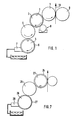
- the 1 comprises a blanket cylinder 1 and a forme cylinder 2, onto which a printing form 3 suitable for offset printing is clamped.
- the forme cylinder 2 interacts with an inking roller 4, which has a resilient ink-accepting surface.
- the ink is applied to the inking roller 4 by an anilox roller 5.
- a screen jacket 6, designed as a screen plate, is clamped onto the screen roller 5.
- the diameter of the screen roller 5 covered with the screen jacket 6 is equal to the diameter of the ready-to-use forme cylinder 2.
- the forme cylinder 2 and the rollers 4, 5 are driven at the same speed.
- the inking roller 4 also has the same diameter.
- the plate forming the grid jacket 6 is made of a hard material with a flat surface into which wells are introduced.
- an intaglio wrapping plate as shown in detail in FIGS. 3 and 5, is used as the grid jacket 6.
- a chambered doctor blade 7 is placed on the anilox roller, with which ink is simultaneously fed to the anilox roller 6 and then its surface is doctored off becomes.
- a dampening unit 8 of any type, indicated only schematically, is provided, with which dampening solution can be applied to the forme cylinder 2.
- an impression cylinder 9 is provided with which a printing material web 10 is pressed onto the blanket cylinder 1.
- the impression cylinder 9 can be the blanket cylinder of another printing unit.
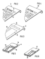
- Fig. 2 shows that the printing form 3 has a plurality of printing areas 11, 12, 13, between which non-printing areas remain. If the printing form according to FIG. 2 is to be used for printing, a grid jacket 6 according to FIG. 3 is produced, which is provided with ink-receiving areas 14, 15, 16, between which ink-repellent areas lie.
- the printing form 3 and the grid jacket 6 are then clamped onto the forme cylinder 2 or the screen roller 5.
- the grid jacket 6 is clamped in such a way that the ink picked up by the area 14 is passed on via the inking roller 4 to the printing area 11 of the printing form 3.
- the ink picked up by the areas 15, 16 is guided via the inking roller 4 to the areas 12, 13 of the printing form 3.
- the ink-receiving areas of the grid jacket 6 are formed by cells 17 which are introduced into a photopolymer layer 18.
- the photopolymer layer 18 is firmly connected to a carrier layer 19.
- each ink-guiding cup of the grid jacket 20 guides an ink particle via the inking roller 4 to a location on the printing form 3 where this ink particle is required immediately.
- a screen printing plate can be used as a grid jacket 21.
- cups 22 are provided, which go through the entire thickness of the screen printing plate. The bottom of these cups 22 is formed by the surface of the anilox roller 5.
- the application of the method according to the invention is not restricted to offset printing units.
- a forme cylinder 23 is provided which can be covered with hard high-pressure plates 24.
- the ink is in turn fed to the forme cylinder 23 by means of an applicator roller 25 with a resilient, ink-accepting surface.
- the application roller 25 is in contact with an anilox roller 26, to which a raster jacket 27 is applied, which is provided with cells only in the printing areas.
- the grid jacket 27 is designed as an exchangeable sleeve.
- a chambered doctor blade 28 is provided for ink supply. Any other known doctor blade inking unit can also be used for the ink supply.
- the forme cylinder 23, the anilox roller 26 and the applicator roller 25 have the same diameter and are driven at the same speed.
- the grid jacket 27 is produced with a well configuration that is either only partially or precisely tailored to the color requirements of the high-pressure mold 24.
- the printing form and screen jacket are then clamped onto the forme cylinder 23 or the screen roller 26.
- the method according to the invention can also be used in flexographic printing units.
- the printing form and the screen jacket are applied to the forme cylinder or the screen roller that is in direct contact with it.
- the main advantage of the invention can be seen in the fact that any additional adjustment or control means can be used to adapt the color conveyed by the anilox roller to the ink requirement of the forme cylinder, both in the circumferential and in the lateral direction. Since the cups of the grid jacket can be produced in different depths, this can be adapted to the color to be used in each case.
Abstract
Description
Die Erfindung betrifft ein Verfahren zur Druckvorbereitung eines Druckwerks, das mindestens ein Farbwerk mit einer mit einer Rakel zusammenwirkenden Rasterwalze umfaßt, die mit einem mit farbführenden Näpfchen versehenen, auswechselbaren Rastermantel belegbar, die mit Formzylinderdrehzahl angetrieben und deren Durchmesser in betriebsbereitem Zustand gleich dem Druchmesser des mit einer Druckform belegten Formzylinders ist sowie ein zur Durchführung des Verfahrens geeignetes Druckwerk.The invention relates to a method for printing preparation of a printing unit, which comprises at least one inking unit with an anilox roller interacting with a doctor blade, which can be coated with an interchangeable raster jacket provided with ink-guiding cups, which is driven by the forme cylinder speed and whose diameter in the operational state is equal to the diameter of the a printing form occupied by a forme cylinder and a printing unit suitable for carrying out the method.
Aus der DE-OS 37 06 011 ist ein Farbwerk mit einer Rasterwalze bekannt, deren Näpfchen in einer kompressiblen Trägerschicht, die auch als auswechselbare Platte ausgebildet sein kann, angeordnet sind. Durch Änderung des Anpreßdrucks der Rakel wird das Volumen der Näpfchen und damit die Menge der dem Plattenzylinder zugeführten Farbe geändert. Eine Änderung der übertragenen Farbmenge zwischen bestimmten Bereichen der Rasterplatte ist jedoch nicht vorgesehen. Außerdem unterliegt die Anordnung wegen der Anstellung der Rakel an eine nachgiebige Schicht einem verhältnismäßig hohen Verschleiß.From DE-OS 37 06 011 an inking unit with an anilox roller is known, the cells of which are arranged in a compressible carrier layer, which can also be designed as an exchangeable plate. By changing the contact pressure of the doctor blade, the volume of the cells and thus the amount of ink supplied to the plate cylinder are changed. A change in the amount of color transferred between certain areas of the grid plate is not provided. In addition, the arrangement is subject to a relatively high level of wear due to the fact that the doctor blade is positioned against a flexible layer.
Der Erfindung liegt die Aufgabe zugrunde, ein Verfahren und eine zu seiner Durchführung geeignete Vorrichtung zu schaffen, mit dem eine exakte Dosierung der dem Formzylinder zuzuführenden Farbe, sowohl in Umfangsrichtung als auch in Längsrichtung der Rasterwalze bei geringem Verschleiß der Teile ermöglicht wird.The invention has for its object to provide a method and a device suitable for its implementation, with an exact dosage of the ink to be supplied to the forme cylinder, both in the circumferential direction and in the longitudinal direction of the anilox roller with little wear of the parts is made possible.
Erfindungsgemäß wird diese Aufgabe durch die Anwendung der Merkmale des Anspruchs 1 gelöst.According to the invention, this object is achieved by applying the features of
Ausführungsbeispiele der Erfindung sind anhand der Zeichnung beschrieben. In dieser zeigt
- Fig. 1 eine schematische Darstellung eines Offsetdruckwerkes und
- Fig. 2 eine zum Druck verbreitete Offsetdruckform,
- Fig. 3 eine erste Variante einer erfindungsgemäßen Rasterplatte,
- Fig. 4 eine zweite Variante einer derartigen Platte,
- Fig. 5 einen Ausschnitt aus einer Rasterplatte,
- Fig. 6 einen Ausschnitt aus einer anderen Rasterplatte,
- Fig. 7 eine schematische Darstellung eines Hochdruckfarbwerkes.
- Fig. 1 is a schematic representation of an offset printing unit and
- 2 is an offset printing form widely used for printing,
- 3 shows a first variant of a grid plate according to the invention,
- 4 shows a second variant of such a plate,
- 5 shows a section of a grid plate,
- 6 shows a detail from another grid plate,
- Fig. 7 is a schematic representation of a high-pressure inking unit.
Das zur Durchführung des erfindungsgemäßen Verfahrens geeignete Offsetdruckwerk nach Fig. 1 umfaßt einen Gummituchzylinder 1 und einen Formzylinder 2, auf den eine für den Offsetdruck geeignete Druckform 3 aufgespannt ist. Der Formzylinder 2 wirkt mit einer Farbauftragwalze 4 zusammen, die eine nachgiebige farbannehmende Oberfläche aufweist. Der Farbauftragwalze 4 wird die Farbe von einer Rasterwalze 5 zugeführt. Auf die Rasterwalze 5 ist ein als Rasterplatte ausgebildeter Rastermantel 6 aufgespannt. Der Durchmesser der mit dem Rastermantel 6 belegten Rasterwalze 5 ist gleich dem Durchmesser des betriebsbereiten Formzylinders 2. Der Formzylinder 2 und die Walzen 4, 5 werden mit gleicher Drehzahl angetrieben. Auch die Farbauftragwalze 4 weist den gleichen Durchmesser auf. Die den Rastermantel 6 bildende Platte besteht aus einem harten Material mit einer ebenen Oberfläche, in die Näpfchen eingebracht werden. Beim dargestellten Ausführungsbeispiel findet als Rastermantel 6 eine Tiefdruckwickelplatte Verwendung, wie sie im einzelnen in den Figuren 3 und 5 dargestellt ist. An die Rasterwalze ist eine Kammerrakel 7 angestellt, mit der gleichzeitig Farbe zur Rasterwalze 6 geführt und anschließend deren Oberfläche abgerakelt wird. Weiterhin ist ein nur schematisch angedeutetes Feuchtwerk 8 beliebiger Bauart vorgesehen, mit dem Feuchtmittel auf den Formzylinder 2 aufgetragen werden kann. Letztlich ist ein Gegendruckzylinder 9 vorgesehen, mit dem eine Bedruckstoffbahn 10 an den Gummituchzylinder 1 angedrückt wird. Der Gegendruckzylinder 9 kann dabei der Gummituchzylinder eines weiteren Druckwerkes sein.1 comprises a
Fig. 2 läßt erkennen, daß die Druckform 3 mehrere druckende Bereiche 11, 12, 13 aufweist, zwischen denen nichtdruckende Bereiche verbleiben. Wenn mit der Druckform nach Fig. 2 gedruckt werden soll, wird ein Rastermantel 6 nach Fig. 3 hergestellt, der mit farbaufnehmenden Bereichen 14, 15, 16 versehen wird, zwischen denen farbabstoßende Bereiche liegen.Fig. 2 shows that the
Anschließend werden die Druckform 3 und der Rastermantel 6 auf den Formzylinder 2 bzw. die Rasterwalze 5 aufgespannt. Die Aufspannung des Rastermantels 6 erfolgt dabei so, daß die vom Bereich 14 aufgenommene Farbe über die Farbauftragwalze 4 zum druckenden Bereich 11 der Druckform 3 weitergeleitet wird. In gleicher Weise wird die von den Bereichen 15, 16 aufgenommene Farbe über die Farbauftragwalze 4 zu den Bereichen 12, 13 der Druckform 3 geführt.The
Die farbaufnehmenden Bereiche der Rastermantels 6 werden dabei, wie Fig. 5 zeigt, durch Näpfchen 17 gebildet, die in eine Photopolymerschicht 18 eingebracht werden. Die Photopolymerschicht 18 ist fest mit einer Trägerschicht 19 verbunden.As shown in FIG. 5, the ink-receiving areas of the
Durch diese Maßnahmen wird erreicht, daß der Rastermantel 6 nur in den Bereichen Farbe aufnimmt und weiterleitet, in denen tatsächlich ein Farbbedarf der Druckplatte vorliegt.These measures ensure that the
Während bei dem Rastermantel 6 gemäß Fig. 3 in den Bereichen 14 bis 16 eine gleichmäßige Näpfchenverteilung vorgesehen ist, erfolgt bei dem Rastermantel 20 gemäß Fig. 4 eine noch exaktere Farbdosierung. Hierzu ist das zu druckende Sujet der Druckform 3 auf denWhile in the
Rastermantel 20 in allen Einzelheiten aufgebracht. Infolgedessen führt jedes farbführende Näpfchen des Rastermantels 20 ein Farbpartikel über die Farbauftragwalze 4 zu einer Stelle der Druckform 3, an der dieses Farbpartikel unmittelbar benötigt wird.
Anstelle einer Tiefdruckwechselplatte als Rastermantel kann auch, vgl. Fig. 6, eine Siebdruckplatte als Rastermantel 21 Verwendung finden. In dieser sind Näpfchen 22 vorgesehen, die durch die gesamte Dicke der Siebdruckplatte hindurchgehen. Der Boden dieser Näpfchen 22 wird durch die Oberfläche der Rasterwalze 5 gebildet.Instead of a gravure changing plate as a grid jacket, cf. Fig. 6, a screen printing plate can be used as a
Wie Fig. 7 zeigt, ist die Anwendung des erfindungsgemäßen Verfahrens nicht auf Offsetdruckwerke beschränkt. Bei dem Druckwerk gemäß Fig. 7 ist ein Formzylinder 23 vorgesehen, der mit harten Hochdruckplatten 24 belegbar ist. Dem Formzylinder 23 wird dabei die Farbe wiederum mittels einer Auftragwalze 25 mit einer nachgiebigen, farbannehmenden Oberfläche zugeführt. Die Auftragwalze 25 steht in Kontakt mit einer Rasterwalze 26, auf die ein Rastermantel 27 aufgebracht ist, der lediglich in den druckenden Bereichen mit Näpfchen versehen ist. Der Rastermantel 27 ist als auswechselbare Hülse ausgebildet. Zur Farbzufuhr ist eine Kammerrakel 28 vorgesehen. Zur Farbzufuhr ist aber auch jedes andere bekannte Rakelfarbwerk einsetzbar. In betriebsbereitem Zustand weisen der Formzylinder 23, die Rasterwalze 26 und die Auftragwalze 25 gleiche Durchmesser auf und werden mit gleicher Drehzahl angetrieben.As FIG. 7 shows, the application of the method according to the invention is not restricted to offset printing units. In the printing unit according to FIG. 7, a
Auch bei dieser Ausführungsform wird der Rastermantel 27 mit einer Näpfchenkonfiguration hergestellt, die entweder nur bereichsweise oder genau auf den Farbbedarf der Hochdruckform 24 abgestellt ist. Anschließend werden Druckform und Rastermantel auf den Formzylinder 23 bzw. die Rasterwalze 26 aufgespannt.In this embodiment, too, the
Das erfindungsgemäße Verfahren ist auch bei Flexodruckwerken anwendbar. Hier werden die Druckform und der Rastermantel auf den Formzylinder bzw. die damit unmittelbar in Kontakt stehende Rasterwalze aufgebracht.The method according to the invention can also be used in flexographic printing units. Here the printing form and the screen jacket are applied to the forme cylinder or the screen roller that is in direct contact with it.
Der wesentliche Vorteil der Erfindung ist darin zu sehen, daß ohne zusätzliche Stell- oder Steuermittel eine beliebig genaue Anpassung der von der Rasterwalze weitergeführten Farbe an den Farbbedarf des Formzylinders und zwar sowohl im Umfangs- als auch in Seitenrichtung erfolgen kann. Da die Näpfchen des Rastermantels in unterschiedlicher Tiefe hergestellt werden können, kann hierdurch eine Anpassung an die jeweils zu verwendende Farbe erfolgen.The main advantage of the invention can be seen in the fact that any additional adjustment or control means can be used to adapt the color conveyed by the anilox roller to the ink requirement of the forme cylinder, both in the circumferential and in the lateral direction. Since the cups of the grid jacket can be produced in different depths, this can be adapted to the color to be used in each case.
Claims (10)
Applications Claiming Priority (2)
| Application Number | Priority Date | Filing Date | Title |
|---|---|---|---|
| DE3938448 | 1989-11-18 | ||
| DE3938448 | 1989-11-18 |
Publications (3)
| Publication Number | Publication Date |
|---|---|
| EP0428894A2 true EP0428894A2 (en) | 1991-05-29 |
| EP0428894A3 EP0428894A3 (en) | 1991-11-06 |
| EP0428894B1 EP0428894B1 (en) | 1995-06-28 |
Family
ID=6393837
Family Applications (1)
| Application Number | Title | Priority Date | Filing Date |
|---|---|---|---|
| EP90120396A Expired - Lifetime EP0428894B1 (en) | 1989-11-18 | 1990-10-24 | Method of preparing a printing unit and printing unit adapted for this method |
Country Status (4)
| Country | Link |
|---|---|
| US (1) | US5134936A (en) |
| EP (1) | EP0428894B1 (en) |
| JP (1) | JPH03169555A (en) |
| DE (1) | DE59009335D1 (en) |
Cited By (3)
| Publication number | Priority date | Publication date | Assignee | Title |
|---|---|---|---|---|
| FR2707555A1 (en) * | 1993-07-17 | 1995-01-20 | Roland Man Druckmasch | Inking roller with elastic coating stretched over a core. |
| FR2723883A1 (en) * | 1994-08-30 | 1996-03-01 | Metronic Geraetebau | PRINTING DEVICE FOR PRINTING PLASTIC CARDS. |
| WO2007099148A3 (en) * | 2006-03-03 | 2008-01-03 | Koenig & Bauer Ag | Printing groups of a printing press |
Families Citing this family (6)
| Publication number | Priority date | Publication date | Assignee | Title |
|---|---|---|---|---|
| JPH04371838A (en) * | 1991-06-20 | 1992-12-24 | Canon Inc | Transfer printer and production of liquid crystal element |
| JP3116591B2 (en) * | 1992-09-28 | 2000-12-11 | ソニー株式会社 | Printing equipment |
| IL116123A (en) * | 1995-11-23 | 1999-07-14 | Scitex Corp Ltd | System and method for printing |
| DE102006030290B3 (en) * | 2006-03-03 | 2007-10-18 | Koenig & Bauer Aktiengesellschaft | printing unit |
| DE102006031682A1 (en) * | 2006-07-08 | 2008-01-10 | Man Roland Druckmaschinen Ag | Flexographic printing roller and flexographic printing process |
| IT1402297B1 (en) * | 2010-09-08 | 2013-08-28 | Uteco Converting Spa | CYLINDER STRUCTURE PARTICULARLY FINISHED FOR FLEXOGRAPHIC PRINTING MACHINES |
Citations (4)
| Publication number | Priority date | Publication date | Assignee | Title |
|---|---|---|---|---|
| EP0101266A2 (en) * | 1982-08-09 | 1984-02-22 | Milliken Research Corporation | Printing method and apparatus |
| US4672893A (en) * | 1985-03-21 | 1987-06-16 | Paramount Packaging | Flexo-gravure printing |
| EP0279295A2 (en) * | 1987-02-19 | 1988-08-24 | Albert-Frankenthal AG | Inking unit |
| EP0280140A2 (en) * | 1987-02-25 | 1988-08-31 | M.A.N.-ROLAND Druckmaschinen Aktiengesellschaft | Method to transfer ink using a screen roller |
Family Cites Families (10)
| Publication number | Priority date | Publication date | Assignee | Title |
|---|---|---|---|---|
| NL67009C (en) * | 1947-10-06 | |||
| US3044396A (en) * | 1959-01-02 | 1962-07-17 | Carl Allers Ets | Inking mechanism for intaglio printing machines |
| US3392667A (en) * | 1965-06-07 | 1968-07-16 | Interchem Corp | Multicolor electrostatic printing |
| US3738266A (en) * | 1967-07-25 | 1973-06-12 | Matsushita Electric Ind Co Ltd | Electronic printing device |
| US3814014A (en) * | 1968-06-17 | 1974-06-04 | H Dahlgren | Inker |
| US3910186A (en) * | 1973-10-15 | 1975-10-07 | American Bank Note Co | Ink supply apparatus for intaglio printing press |
| US4130056A (en) * | 1977-08-01 | 1978-12-19 | Addressograph-Multigraph Corporation | Lithographic moisture system and method |
| DE3412783C2 (en) * | 1984-04-05 | 1986-09-25 | Heidelberger Druckmaschinen Ag, 6900 Heidelberg | Printing unit of a web-fed rotary offset printing machine |
| US4676157A (en) * | 1985-05-28 | 1987-06-30 | Komori Printing | Wiping apparatus for intaglio printing machine |
| US4901641A (en) * | 1988-11-30 | 1990-02-20 | Bobst Sa | Printing press |
-
1990
- 1990-10-24 EP EP90120396A patent/EP0428894B1/en not_active Expired - Lifetime
- 1990-10-24 DE DE59009335T patent/DE59009335D1/en not_active Expired - Fee Related
- 1990-10-26 US US07/604,772 patent/US5134936A/en not_active Expired - Fee Related
- 1990-11-16 JP JP2308966A patent/JPH03169555A/en active Pending
Patent Citations (4)
| Publication number | Priority date | Publication date | Assignee | Title |
|---|---|---|---|---|
| EP0101266A2 (en) * | 1982-08-09 | 1984-02-22 | Milliken Research Corporation | Printing method and apparatus |
| US4672893A (en) * | 1985-03-21 | 1987-06-16 | Paramount Packaging | Flexo-gravure printing |
| EP0279295A2 (en) * | 1987-02-19 | 1988-08-24 | Albert-Frankenthal AG | Inking unit |
| EP0280140A2 (en) * | 1987-02-25 | 1988-08-31 | M.A.N.-ROLAND Druckmaschinen Aktiengesellschaft | Method to transfer ink using a screen roller |
Non-Patent Citations (1)
| Title |
|---|
| POLYGRAPH. Bd. 26, Nr. 9, 5. Mai 1973, FRANKFURT/MAIN DE Seiten 632 - 636; 'Indirekter Tiefdruck als Erg{nzung und Verbindung von Flexo- und Tiefdruck ' * |
Cited By (8)
| Publication number | Priority date | Publication date | Assignee | Title |
|---|---|---|---|---|
| FR2707555A1 (en) * | 1993-07-17 | 1995-01-20 | Roland Man Druckmasch | Inking roller with elastic coating stretched over a core. |
| GB2280148A (en) * | 1993-07-17 | 1995-01-25 | Roland Man Druckmasch | Inking roller |
| GB2280148B (en) * | 1993-07-17 | 1997-07-23 | Roland Man Druckmasch | Inking roller |
| FR2723883A1 (en) * | 1994-08-30 | 1996-03-01 | Metronic Geraetebau | PRINTING DEVICE FOR PRINTING PLASTIC CARDS. |
| NL1001101C2 (en) * | 1994-08-30 | 1997-06-04 | Metronic Geraetebau | Printing device for printing plastic cards. |
| AT408633B (en) * | 1994-08-30 | 2002-01-25 | Metronic Ag | PRINTING DEVICE FOR PRINTING PLASTIC CARDS |
| CN1085966C (en) * | 1994-08-30 | 2002-06-05 | 梅特龙尼工具制造公司 | Printing plastic cards |
| WO2007099148A3 (en) * | 2006-03-03 | 2008-01-03 | Koenig & Bauer Ag | Printing groups of a printing press |
Also Published As
| Publication number | Publication date |
|---|---|
| US5134936A (en) | 1992-08-04 |
| DE59009335D1 (en) | 1995-08-03 |
| EP0428894B1 (en) | 1995-06-28 |
| JPH03169555A (en) | 1991-07-23 |
| EP0428894A3 (en) | 1991-11-06 |
Similar Documents
| Publication | Publication Date | Title |
|---|---|---|
| EP0078444B1 (en) | Inking arrangement for offset printing machines | |
| DE3116505A1 (en) | "ROTARY PRINTING MACHINE" | |
| DE19731003A1 (en) | Short inking unit | |
| EP0453853A2 (en) | Printing machine with washing device | |
| EP0428894B1 (en) | Method of preparing a printing unit and printing unit adapted for this method | |
| DE4401362C2 (en) | Process and rotary printing machine for indirect gravure printing | |
| EP0518892B1 (en) | Short inking apparatus for a rotary press | |
| EP0771267A1 (en) | Printing unit with short inking system in a rotary printing machine for direct printing using a "waterless" planographic printing plate | |
| DE19934395B4 (en) | Inking unit in a rotary offset printing press with an inking roller to reduce the pearlescent effect of the ink | |
| DE102006046521A1 (en) | Rotary offset printing station has at least one cylinder, e.g. the transfer cylinder, with segments of different diameters along the body axial length to compensate for cylinder bending | |
| EP0453855B1 (en) | Preparation of the inking unit of a printing machine when changing the printing order | |
| DE2462017A1 (en) | Rotogravure printing device | |
| WO1999042291A1 (en) | Sheet-fed letterpress rotary with printing units for multicolour printing and at least one coating unit | |
| EP0085752B1 (en) | Printing unit for a rotary offset machine | |
| DE4401425C2 (en) | Printing unit of an offset rotary printing machine | |
| DE19515459C2 (en) | Blanket cylinder | |
| EP0640477A1 (en) | Rotary printing machine for producing newspapers | |
| DE102006031682A1 (en) | Flexographic printing roller and flexographic printing process | |
| DE256705C (en) | ||
| DE3821777C2 (en) | ||
| DE3432909C2 (en) | ||
| DE4021662C2 (en) | Printing machine with electrochemically changeable printing form | |
| DD238575A1 (en) | painting equipment | |
| DE3327792C2 (en) | Process for the production of a perfecting with a convertible sheet-fed offset rotary printing machine of the five-cylinder type | |
| DE19527889A1 (en) | Inking device for inking water=free flat printing plate - has ink supply roll in form of screen roll with surface temp. above 30 deg C |
Legal Events
| Date | Code | Title | Description |
|---|---|---|---|
| PUAI | Public reference made under article 153(3) epc to a published international application that has entered the european phase |
Free format text: ORIGINAL CODE: 0009012 |
|
| AK | Designated contracting states |
Kind code of ref document: A2 Designated state(s): CH DE FR GB IT LI |
|
| PUAL | Search report despatched |
Free format text: ORIGINAL CODE: 0009013 |
|
| AK | Designated contracting states |
Kind code of ref document: A3 Designated state(s): CH DE FR GB IT LI |
|
| 17P | Request for examination filed |
Effective date: 19911018 |
|
| 17Q | First examination report despatched |
Effective date: 19931129 |
|
| GRAA | (expected) grant |
Free format text: ORIGINAL CODE: 0009210 |
|
| ITF | It: translation for a ep patent filed |
Owner name: BARZANO' E ZANARDO ROMA S.P.A. |
|
| AK | Designated contracting states |
Kind code of ref document: B1 Designated state(s): CH DE FR GB IT LI |
|
| REF | Corresponds to: |
Ref document number: 59009335 Country of ref document: DE Date of ref document: 19950803 |
|
| ET | Fr: translation filed | ||
| GBT | Gb: translation of ep patent filed (gb section 77(6)(a)/1977) |
Effective date: 19951016 |
|
| PLBE | No opposition filed within time limit |
Free format text: ORIGINAL CODE: 0009261 |
|
| STAA | Information on the status of an ep patent application or granted ep patent |
Free format text: STATUS: NO OPPOSITION FILED WITHIN TIME LIMIT |
|
| 26N | No opposition filed | ||
| PGFP | Annual fee paid to national office [announced via postgrant information from national office to epo] |
Ref country code: GB Payment date: 19980914 Year of fee payment: 9 |
|
| PGFP | Annual fee paid to national office [announced via postgrant information from national office to epo] |
Ref country code: FR Payment date: 19980916 Year of fee payment: 9 |
|
| PGFP | Annual fee paid to national office [announced via postgrant information from national office to epo] |
Ref country code: DE Payment date: 19980922 Year of fee payment: 9 |
|
| PGFP | Annual fee paid to national office [announced via postgrant information from national office to epo] |
Ref country code: CH Payment date: 19980929 Year of fee payment: 9 |
|
| PG25 | Lapsed in a contracting state [announced via postgrant information from national office to epo] |
Ref country code: GB Free format text: LAPSE BECAUSE OF NON-PAYMENT OF DUE FEES Effective date: 19991024 |
|
| PG25 | Lapsed in a contracting state [announced via postgrant information from national office to epo] |
Ref country code: LI Free format text: LAPSE BECAUSE OF NON-PAYMENT OF DUE FEES Effective date: 19991031 Ref country code: CH Free format text: LAPSE BECAUSE OF NON-PAYMENT OF DUE FEES Effective date: 19991031 |
|
| GBPC | Gb: european patent ceased through non-payment of renewal fee |
Effective date: 19991024 |
|
| REG | Reference to a national code |
Ref country code: CH Ref legal event code: PL |
|
| PG25 | Lapsed in a contracting state [announced via postgrant information from national office to epo] |
Ref country code: FR Free format text: LAPSE BECAUSE OF NON-PAYMENT OF DUE FEES Effective date: 20000630 |
|
| PG25 | Lapsed in a contracting state [announced via postgrant information from national office to epo] |
Ref country code: DE Free format text: LAPSE BECAUSE OF NON-PAYMENT OF DUE FEES Effective date: 20000801 |
|
| REG | Reference to a national code |
Ref country code: FR Ref legal event code: ST |
|
| PG25 | Lapsed in a contracting state [announced via postgrant information from national office to epo] |
Ref country code: IT Free format text: LAPSE BECAUSE OF NON-PAYMENT OF DUE FEES;WARNING: LAPSES OF ITALIAN PATENTS WITH EFFECTIVE DATE BEFORE 2007 MAY HAVE OCCURRED AT ANY TIME BEFORE 2007. THE CORRECT EFFECTIVE DATE MAY BE DIFFERENT FROM THE ONE RECORDED. Effective date: 20051024 |