EP0428675B1 - A valve unit for a reciprocating compressor for refrigerators and the like - Google Patents
A valve unit for a reciprocating compressor for refrigerators and the like Download PDFInfo
- Publication number
- EP0428675B1 EP0428675B1 EP90908518A EP90908518A EP0428675B1 EP 0428675 B1 EP0428675 B1 EP 0428675B1 EP 90908518 A EP90908518 A EP 90908518A EP 90908518 A EP90908518 A EP 90908518A EP 0428675 B1 EP0428675 B1 EP 0428675B1
- Authority
- EP
- European Patent Office
- Prior art keywords
- valve
- reed
- exhaust
- plate
- base portion
- Prior art date
- Legal status (The legal status is an assumption and is not a legal conclusion. Google has not performed a legal analysis and makes no representation as to the accuracy of the status listed.)
- Expired - Lifetime
Links
- 235000014676 Phragmites communis Nutrition 0.000 claims abstract description 57
- 230000000452 restraining effect Effects 0.000 claims 1
- 238000005452 bending Methods 0.000 description 6
- 230000008901 benefit Effects 0.000 description 6
- 229910000831 Steel Inorganic materials 0.000 description 5
- 239000010959 steel Substances 0.000 description 5
- 230000003584 silencer Effects 0.000 description 3
- 230000006835 compression Effects 0.000 description 2
- 238000007906 compression Methods 0.000 description 2
- 241001137251 Corvidae Species 0.000 description 1
- 238000013016 damping Methods 0.000 description 1
- 230000036316 preload Effects 0.000 description 1
Images


Classifications
-
- F—MECHANICAL ENGINEERING; LIGHTING; HEATING; WEAPONS; BLASTING
- F04—POSITIVE - DISPLACEMENT MACHINES FOR LIQUIDS; PUMPS FOR LIQUIDS OR ELASTIC FLUIDS
- F04B—POSITIVE-DISPLACEMENT MACHINES FOR LIQUIDS; PUMPS
- F04B39/00—Component parts, details, or accessories, of pumps or pumping systems specially adapted for elastic fluids, not otherwise provided for in, or of interest apart from, groups F04B25/00 - F04B37/00
- F04B39/10—Adaptations or arrangements of distribution members
- F04B39/1073—Adaptations or arrangements of distribution members the members being reed valves
-
- F—MECHANICAL ENGINEERING; LIGHTING; HEATING; WEAPONS; BLASTING
- F16—ENGINEERING ELEMENTS AND UNITS; GENERAL MEASURES FOR PRODUCING AND MAINTAINING EFFECTIVE FUNCTIONING OF MACHINES OR INSTALLATIONS; THERMAL INSULATION IN GENERAL
- F16K—VALVES; TAPS; COCKS; ACTUATING-FLOATS; DEVICES FOR VENTING OR AERATING
- F16K15/00—Check valves
- F16K15/14—Check valves with flexible valve members
- F16K15/16—Check valves with flexible valve members with tongue-shaped laminae
-
- F—MECHANICAL ENGINEERING; LIGHTING; HEATING; WEAPONS; BLASTING
- F16—ENGINEERING ELEMENTS AND UNITS; GENERAL MEASURES FOR PRODUCING AND MAINTAINING EFFECTIVE FUNCTIONING OF MACHINES OR INSTALLATIONS; THERMAL INSULATION IN GENERAL
- F16K—VALVES; TAPS; COCKS; ACTUATING-FLOATS; DEVICES FOR VENTING OR AERATING
- F16K15/00—Check valves
- F16K15/14—Check valves with flexible valve members
- F16K15/16—Check valves with flexible valve members with tongue-shaped laminae
- F16K15/161—Check valves with flexible valve members with tongue-shaped laminae with biasing means in addition to material resiliency, e.g. spring
-
- F—MECHANICAL ENGINEERING; LIGHTING; HEATING; WEAPONS; BLASTING
- F16—ENGINEERING ELEMENTS AND UNITS; GENERAL MEASURES FOR PRODUCING AND MAINTAINING EFFECTIVE FUNCTIONING OF MACHINES OR INSTALLATIONS; THERMAL INSULATION IN GENERAL
- F16K—VALVES; TAPS; COCKS; ACTUATING-FLOATS; DEVICES FOR VENTING OR AERATING
- F16K15/00—Check valves
- F16K15/14—Check valves with flexible valve members
- F16K15/16—Check valves with flexible valve members with tongue-shaped laminae
- F16K15/162—Check valves with flexible valve members with tongue-shaped laminae with limit stop
-
- Y—GENERAL TAGGING OF NEW TECHNOLOGICAL DEVELOPMENTS; GENERAL TAGGING OF CROSS-SECTIONAL TECHNOLOGIES SPANNING OVER SEVERAL SECTIONS OF THE IPC; TECHNICAL SUBJECTS COVERED BY FORMER USPC CROSS-REFERENCE ART COLLECTIONS [XRACs] AND DIGESTS
- Y10—TECHNICAL SUBJECTS COVERED BY FORMER USPC
- Y10T—TECHNICAL SUBJECTS COVERED BY FORMER US CLASSIFICATION
- Y10T137/00—Fluid handling
- Y10T137/7722—Line condition change responsive valves
- Y10T137/7837—Direct response valves [i.e., check valve type]
- Y10T137/7879—Resilient material valve
- Y10T137/7888—With valve member flexing about securement
- Y10T137/7891—Flap or reed
- Y10T137/7892—With stop
Definitions
- the present invention relates to a valve unit for a reciprocating compressor with a cylinder and a piston for refrigerators and the like, according to the preamble of Claim 1.
- a valve unit of the type in question is known from the document US-A-4,642,037 and includes an exhaust valve reed with a base portion fixed to the valve plate by means of rivets.
- One of these rivets is substantially on the longitudinal axis of the valve reed.
- valve reed behaves like a beam which is fixed at its end remote from the obturator head.
- This type of exhaust valve has the advantage of using an exhaust valve reed of quite small mass, which means it has quite a rapid response.
- the flexibility of the valve reed is quite limited since the length of the cantilevered beam which constitutes it cannot be increased beyond a certain limit without increasing the size of the valve unit to an unacceptable extent in the direction in which the valve reed extends.
- the object of the invention is to provide a valve unit of the type in question, including a very flexible exhaust valve reed which provides a large section of opening for the exhaust without giving rise to an unacceptably bulky unit, thus enabling full use to be made of the advantages of an exhaust port of small cross-section.
- the bending axis of the exhaust valve reed is constituted by at least the sum of the lengths of the leg and the foot of the "L".
- the bending length of the reed is increased at least by an amount corresponding to the foot of the "L". Since the part of the reed which corresponds to the foot of the "L” is at right angles to the rest of the reed, other conditions remaining the same, the size of the valve unit is not substantially increased in comparison with the size of an equivalent prior-art unit in which the bending length of the exhaust .valve blade is limited to the distance of the head part from the foot part.
- the motor-compressor includes a hermetic casing 10 which houses the motor-driven compressor proper, generally designated 12.
- the compressor 12 includes an electric motor 14 with a stator pack 16.
- the stator pack 16 is suspended in the casing 10.
- the housing 18 of a reciprocating compressor is fixed to the upper end of the stator pack 16.
- a crankshaft 20 is supported for rotation in the housing 18 and a connecting rod 22 is connected thereto.
- the connecting rod 22 is coupled in turn to a horizontal piston 24 which is slideable in a cylinder 26 formed in the housing 18.
- the cylinder 26 terminates in a head end constituted by a flange 28 which is substantially square in plan.
- a head unit or valve unit, indicated 30 in Figure 1, is fixed to the flange 28 and will be described in detail below.
- An exhaust manifold head 32 and an intake silencer 34 coupled to the head by a clip 36 are associated with the valve unit 30.
- valve 30 this is constituted by an assembly of elements of which the main ones are shown together in Figure 3 and individually in Figures 4 to 9.
- This assembly is fixed to the flange 28, together with the manifold head 32, by means of screws 38.
- the unit 30 includes a pack of plate elements all having substantially the same square outline as the flange 28.
- the first of these elements, indicated 40, is a gasket.
- the second element, indicated 42, is a thin steel valve plate in which, amongst other things, an intake valve reed 44 is formed.
- An exhaust aperture 46 is formed in a base portion of the reed 44 and communicates with the interior of the cylinder 26.
- the valve plate 42 also has two apertures 48, 48a. One of these apertures, indicated 48, communicates with an exhaust duct 50 which, in known manner, leads from the front face of the flange 28 to an exhaust silencer.
- the other aperture 48a serves to enable the plate 42 to be mounted in either of two positions at 180°.
- the third element of the pack is a relatively thick valve plate 50.
- the plate 50 is preferably of sintered steel.
- the plate 50 has a "C"-shaped recess 52 in its face opposite that which faces the valve plate 42.
- the plate 50 has an inlet port 54 with which the intake valve reed 44 cooperates in known manner, as well as an aperture 55 which enables communication between the interior of the manifold head 32 and the aperture 48 in the flange 28.
- An exhaust port 56 is situated in the centre of the recess 52 and communicates with the interior of the cylinder 26 through the aperture 46 of the intake valve reed 44.
- the port 56 in the recess 52 is surrounded by the usual annular projection 58 which acts on the exhaust valve seat.
- the recess 52 houses, in succession from left to right in Figure 2 and from right to left in Figure 3, an exhaust valve reed 60, a damping blade spring 62, and a means 64 for limiting the opening.Further details of these elements 60, 62, 64 will be given below.
- a fourth element of the pack is constituted by a flat washer 66 ( Figure 2) with an aperture 68 of a "C"-shape corresponding to that of the recess 52.
- the washer 66 also has an aperture 70 for communication between the inlet port 54 and the silencer 34.
- the exhaust valve reed 60 is of thin sheet steel and is generally "U"-shaped in plan.
- a smaller arm of the "U” is formed by a base portion 66 which is restrained in the recess 52 of the valve plate 50 in the manner which will be specified below.
- a portion 68 corresponding to the crows member of the "U” and a longer arm of the "U” are formed by blanking.
- the longer arm which extends parallel to and alongside the base portion 66, includes a connecting portion 70 with a double taper and a drop-shaped head portion 72 which constitutes an obturator and cooperates with the valve seat 58 in the plate 50.
- the spring 62 associated with the valve reed 60 is also of blanked sheet steel. Its function, which is known, is to increase the resistance to bending of the reed 60 towards the end of its opening stroke.
- the spring 62 may be omitted from certain embodiments.
- the blade spring 62 has a similar shape to the valve reed 60.
- it has a base portion 74 which corresponds to the base portion 76, a cross member 76 which corresponds to the cross member 68, and an elongate tapered portion 78 which corresponds to the connecting portion 70 and the head portion 72 of the valve reed 60.
- the elongate portion 78 extends beyond the head portion 72 of the valve reed 60.
- the free end of the elongate portion 78 is indicated 80.
- a bend 82 is formed at the end of the elongate portion 78 of the spring 62 and in a central region of its base portion 74 and serves to preload the spring 62 so as to ensure that its elongate portion 78 is constantly against the connecting portion 70 and the head portion 72 of the valve reed 60.
- the travel-limiting means is constituted by a rigid pressed- or sintered-steel element and in plan has a "C"-shape corresponding to that of the recess 52.
- the limiting means 64 comprises two arms 84, 86 and a yoke 88. Hear their ends remote from the yoke 88, the arms have respective holes 90 which correspond with through-holes 92 formed in the valve plate 50.
- respective rivets 94 extend through the holes 90, 92 and fix the limiter 64 securely in the recess 52 of the plate 50 with the interposition of the valve reed 60 and its spring 62.
- the arm 84 of the limiting means 64 has a region 96 of connection to the yoke.
- a space S wider than the combined thickness T of the valve reed 60 and the spring 62 is left between the connecting region 96 and the base of the recess 52 ( Figure 11).
- the limiting means 64 has a pair of bosses 98 ( Figures 11 and 12) which extend through corresponding holes 100 and 102 and are engaged in corresponding recesses 104 formed in the base of the recess 52.
- the bosses 98 keep the valve reed 60 and its spring 62 in the correct position by means of their respective base portions 66 and 74.
- the end of the yoke 88 corresponding to the other arm 86 of the limiting device 64 is similarly offset as shown at 104' so that a space H wider than the thickness of the spring 62 is left between the end and the base of the recess 52 ( Figure 11).
- the central portion of the yoke 88 is offset away from the base of the recess 52, projects therefrom, and is housed in the exhaust manifold 32.
- the bending axis of the valve reed 60 is indicated A.
- the axis A has at least one "L"-shaped portion which corresponds to the leg of the "L” constituted by the head portion 72 and the connecting portion 70, as well as to the foot of the "L” constituted by the cross member 68.
- the valve reed 60 can therefore bend at least from the head portion 72 up to the point indicated A1 in Figure 5, which corresponds to the first hole 102 on the left in Figures 3 and 5.
- the base portion 66 of the valve reed 60 is floating so that its bending length can be considered to correspond to the distance along the broken axis A between the head portion 72 and the point A2 corresponding to the second, right-hand hole 102 in Figures 3 and 5.
- valve reed 60 is shown in the completely open condition in which it is furthest from its seat 58.
- the distance of the obturator head portion 72 of the reed 60 from the seat 58 is quite large because of the offset configuration of the central portion of the yoke 88.
- a corresponding portion of the spring 62 is interposed between the yoke 88 and the obturator head portion 72. Constant contact is ensured between the elongate part 78 of the spring 62 and the obturator head portion 72: in fact, the free end 80 of the spring 62 is interposed between the corresponding region 104' of the limiter 64 and the base of the recess 52 with clearance H ( Figure 11).
- This free end 80 can move in the directions of the double arrow B ( Figure 12) to enable the elongate part 78 of the spring 62 to bend but is fixed in practice so that, to advantage, the elongate portion 78 behaves like a leaf spring.
Landscapes
- Engineering & Computer Science (AREA)
- General Engineering & Computer Science (AREA)
- Mechanical Engineering (AREA)
- Compressor (AREA)
- Check Valves (AREA)
Abstract
Description
- The present invention relates to a valve unit for a reciprocating compressor with a cylinder and a piston for refrigerators and the like, according to the preamble of Claim 1.
- A valve unit of the type in question is known from the document US-A-4,642,037 and includes an exhaust valve reed with a base portion fixed to the valve plate by means of rivets. One of these rivets is substantially on the longitudinal axis of the valve reed.
- In this known solution, the valve reed behaves like a beam which is fixed at its end remote from the obturator head.
- This type of exhaust valve has the advantage of using an exhaust valve reed of quite small mass, which means it has quite a rapid response. The flexibility of the valve reed, however, is quite limited since the length of the cantilevered beam which constitutes it cannot be increased beyond a certain limit without increasing the size of the valve unit to an unacceptable extent in the direction in which the valve reed extends.
- As is known, in a reciprocating compressor, it is desirable to reduce the cross-section of the port of the exhaust valve as much as possible, in order on the one hand to reduce the residual clearance "volume" in the compression chamber to a minimum, to the benefit of the volumetric efficiency of the compressor, and on the other hand to enable a corresponding reduction in the dimensions of the head portion of the valve reed which cyclically closes the exhaust seat, to make it more silent.
- The smaller the section of the exhaust port, however, the greater must be the flexibility of the valve reed, that is, the further its head portion must travel to open. In other words, the advantages afforded by an exhaust port of small cross-section would be reduced or cancelled out since, with the travel of the head portion of the reed, it is impossible to achieve a section of opening such as to reduce as much as possible the losses of pressure due to the passage of the gas and hence the compression energy of the gas.
- The object of the invention is to provide a valve unit of the type in question, including a very flexible exhaust valve reed which provides a large section of opening for the exhaust without giving rise to an unacceptably bulky unit, thus enabling full use to be made of the advantages of an exhaust port of small cross-section.
- According to the present invention, this object is achieved by means of a valve unit as defined in the characterising part of Claim 1 and in the subsequent claims.
- In a valve unit according to the invention, the bending axis of the exhaust valve reed is constituted by at least the sum of the lengths of the leg and the foot of the "L". In other words, compared with the prior art, the bending length of the reed is increased at least by an amount corresponding to the foot of the "L". Since the part of the reed which corresponds to the foot of the "L" is at right angles to the rest of the reed, other conditions remaining the same, the size of the valve unit is not substantially increased in comparison with the size of an equivalent prior-art unit in which the bending length of the exhaust .valve blade is limited to the distance of the head part from the foot part.
- Further features and advantages of the invention will become clear from the detailed description of a preferred embodiment which follows with reference to the appended drawings, in which:
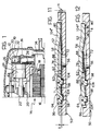
- Figure 1 is a partially-sectioned, partial elevation view of a hermetic compressor for refrigerators and the like incorporating the valve unit according to the invention,
- Figure 2 is an exploded perspective view of the compressor and the valve unit,
- Figure 3 is another exploded perspective view of the main parts of the valve unit, on an enlarged scale,
- Figure 4 is a front view of the valve plate of the unit,
- Figure 5 is a front view of the exhaust valve reed of the unit,
- Figure 6 is a front view of a leaf spring associated with the exhaust valve reed,
- Figure 7 is a front view of a device for limiting the opening of the exhaust valve reed,
- Figure 8 is a cross-section thereof taken in the plane indicated VIII-VIII of Figure 7,
- Figure 9 is a view of the limiting device taken on the arrow IX of Figure 7,
- Figure 10 is a cross-section of the assembled unit formed by the elements of Figures 4 to 7, taken as indicated at X-X in Figure 4,
- Figure 11 is a greatly enlarged cross-section of the unit of Figure 10 taken on the broken line XI-XI of Figure 4 with the exhaust valve closed, and
- Figure 12 is a section corresponding to Figure 11, in which the exhaust valve is shown completely open.
- With reference to Figures 1 and 2, the motor-compressor includes a
hermetic casing 10 which houses the motor-driven compressor proper, generally designated 12. - The
compressor 12 includes anelectric motor 14 with astator pack 16. Thestator pack 16 is suspended in thecasing 10. - The
housing 18 of a reciprocating compressor is fixed to the upper end of thestator pack 16. Acrankshaft 20 is supported for rotation in thehousing 18 and a connectingrod 22 is connected thereto. The connectingrod 22 is coupled in turn to a horizontal piston 24 which is slideable in acylinder 26 formed in thehousing 18. - The
cylinder 26 terminates in a head end constituted by aflange 28 which is substantially square in plan. - A head unit or valve unit, indicated 30 in Figure 1, is fixed to the
flange 28 and will be described in detail below. - An
exhaust manifold head 32 and anintake silencer 34 coupled to the head by aclip 36 are associated with thevalve unit 30. - With reference now to the
valve 30, this is constituted by an assembly of elements of which the main ones are shown together in Figure 3 and individually in Figures 4 to 9. - This assembly is fixed to the
flange 28, together with themanifold head 32, by means ofscrews 38. - From left to right in Figure 2, the
unit 30 includes a pack of plate elements all having substantially the same square outline as theflange 28. The first of these elements, indicated 40, is a gasket. The second element, indicated 42, is a thin steel valve plate in which, amongst other things, anintake valve reed 44 is formed. Anexhaust aperture 46 is formed in a base portion of thereed 44 and communicates with the interior of thecylinder 26. - The
valve plate 42 also has twoapertures exhaust duct 50 which, in known manner, leads from the front face of theflange 28 to an exhaust silencer. Theother aperture 48a serves to enable theplate 42 to be mounted in either of two positions at 180°. - The third element of the pack is a relatively
thick valve plate 50. Theplate 50 is preferably of sintered steel. - The
plate 50 has a "C"-shaped recess 52 in its face opposite that which faces thevalve plate 42. - The
plate 50 has aninlet port 54 with which theintake valve reed 44 cooperates in known manner, as well as anaperture 55 which enables communication between the interior of themanifold head 32 and theaperture 48 in theflange 28. - An
exhaust port 56 is situated in the centre of therecess 52 and communicates with the interior of thecylinder 26 through theaperture 46 of theintake valve reed 44. - The
port 56 in therecess 52 is surrounded by the usualannular projection 58 which acts on the exhaust valve seat. - The
recess 52 houses, in succession from left to right in Figure 2 and from right to left in Figure 3, anexhaust valve reed 60, adamping blade spring 62, and ameans 64 for limiting the opening.Further details of theseelements - A fourth element of the pack is constituted by a flat washer 66 (Figure 2) with an
aperture 68 of a "C"-shape corresponding to that of therecess 52. Thewasher 66 also has anaperture 70 for communication between theinlet port 54 and thesilencer 34. - The
elements - The
exhaust valve reed 60 is of thin sheet steel and is generally "U"-shaped in plan. A smaller arm of the "U" is formed by abase portion 66 which is restrained in therecess 52 of thevalve plate 50 in the manner which will be specified below. Following on from thebase portion 66, in succession, aportion 68 corresponding to the crows member of the "U" and a longer arm of the "U" are formed by blanking. The longer arm, which extends parallel to and alongside thebase portion 66, includes a connectingportion 70 with a double taper and a drop-shaped head portion 72 which constitutes an obturator and cooperates with thevalve seat 58 in theplate 50. - The
spring 62 associated with thevalve reed 60 is also of blanked sheet steel. Its function, which is known, is to increase the resistance to bending of thereed 60 towards the end of its opening stroke. Thespring 62 may be omitted from certain embodiments. - The
blade spring 62 has a similar shape to thevalve reed 60. In particular, it has abase portion 74 which corresponds to thebase portion 76, across member 76 which corresponds to thecross member 68, and an elongatetapered portion 78 which corresponds to the connectingportion 70 and thehead portion 72 of thevalve reed 60. For the reasons which will be specified below, theelongate portion 78 extends beyond thehead portion 72 of thevalve reed 60. The free end of theelongate portion 78 is indicated 80. - A
bend 82 is formed at the end of theelongate portion 78 of thespring 62 and in a central region of itsbase portion 74 and serves to preload thespring 62 so as to ensure that itselongate portion 78 is constantly against the connectingportion 70 and thehead portion 72 of thevalve reed 60. - The travel-limiting means is constituted by a rigid pressed- or sintered-steel element and in plan has a "C"-shape corresponding to that of the
recess 52. In particular, the limitingmeans 64 comprises twoarms yoke 88. Hear their ends remote from theyoke 88, the arms haverespective holes 90 which correspond with through-holes 92 formed in thevalve plate 50. - As illustrated in Figure 10, amongst others,
respective rivets 94 extend through theholes limiter 64 securely in therecess 52 of theplate 50 with the interposition of thevalve reed 60 and itsspring 62. - The
arm 84 of the limitingmeans 64 has aregion 96 of connection to the yoke. For the purpose which will be made clear below, a space S wider than the combined thickness T of thevalve reed 60 and thespring 62 is left between the connectingregion 96 and the base of the recess 52 (Figure 11). - In the connecting
region 96, the limitingmeans 64 has a pair of bosses 98 (Figures 11 and 12) which extend throughcorresponding holes corresponding recesses 104 formed in the base of therecess 52. Thebosses 98 keep thevalve reed 60 and itsspring 62 in the correct position by means of theirrespective base portions - The end of the
yoke 88 corresponding to theother arm 86 of the limitingdevice 64 is similarly offset as shown at 104' so that a space H wider than the thickness of thespring 62 is left between the end and the base of the recess 52 (Figure 11). - The central portion of the
yoke 88 is offset away from the base of therecess 52, projects therefrom, and is housed in theexhaust manifold 32. - In Figures 3 and 5, the bending axis of the
valve reed 60 is indicated A. As can be seen, the axis A has at least one "L"-shaped portion which corresponds to the leg of the "L" constituted by thehead portion 72 and the connectingportion 70, as well as to the foot of the "L" constituted by thecross member 68. Thevalve reed 60 can therefore bend at least from thehead portion 72 up to the point indicated A₁ in Figure 5, which corresponds to thefirst hole 102 on the left in Figures 3 and 5. - By virtue of the difference between the dimensions T-S (Figure 11), the
base portion 66 of thevalve reed 60 is floating so that its bending length can be considered to correspond to the distance along the broken axis A between thehead portion 72 and the point A₂ corresponding to the second, right-hand hole 102 in Figures 3 and 5. - Similar considerations are true of the
spring 62. - In Figure 11, the
head portion 72 of thevalve reed 60 is against itsseat 58 and the exhaust valve is closed. The correspondingelongate part 78 of the spring is against thehead portion 72 of thevalve reed 60. - In Figure 12, the
valve reed 60 is shown in the completely open condition in which it is furthest from itsseat 58. The distance of theobturator head portion 72 of thereed 60 from theseat 58 is quite large because of the offset configuration of the central portion of theyoke 88. - As can be seen in Figure 12, a corresponding portion of the
spring 62 is interposed between theyoke 88 and theobturator head portion 72. Constant contact is ensured between theelongate part 78 of thespring 62 and the obturator head portion 72: in fact, thefree end 80 of thespring 62 is interposed between the corresponding region 104' of thelimiter 64 and the base of therecess 52 with clearance H (Figure 11). Thisfree end 80 can move in the directions of the double arrow B (Figure 12) to enable theelongate part 78 of thespring 62 to bend but is fixed in practice so that, to advantage, theelongate portion 78 behaves like a leaf spring. The sliding of theend 80 in its slot between the region 104' and the base of therecess 52 also generates a frictional force which, added to that of thehead portion 72 of thevalve reed 60 against theelongate portion 78 of thespring 62, opposes undesirable flutter of thehead portion 72.
Claims (8)
- A valve unit for a reciprocating compressor with a cylinder and a piston for refrigerators and the like, comprising a valve plate (50) fitted to a head end (28) of the cylinder (26) of the compressor and having an intake port (54) cooperating with an intake valve reed (44) and an exhaust port (56) surrounded by an annular exhaust seat (58) formed in an opposite face of the plate (50) from that which faces the cylinder (26), an exhaust valve reed (60) associated with the exhaust seat (58) and travel-limiting means (64) fixed to the valve plate (50) for limiting the travel of the exhaust valve reed (60), in which the exhaust valve reed (60) comprises a base portion (66) which is restrained on the valve plate (50), an obturator head portion (72) which is spaced from the base portion (66) and cooperates with the exhaust seat (58), and an elongate connecting portion (68, 70) which connects the base portion (66) and the head portion (72), characterised in that the connecting portion (68, 70) is "L"-shaped in plan with the head portion (72) situated at the end of the leg (70) of the "L" and the base portion (66) situated at the end of the foot (68) of the "L", the foot (68) of the "L" being free to bend with the leg (70) of the "L".
- A valve unit according to Claim 1, characterised in that the base portion (66) of the exhaust valve reed (60) extends from the foot (68) of the "L" alongside and parallel to the leg (70) of the "L" so that the exhaust valve reed (60) is generally "U"-shaped in plan with a shorter arm formed by the base portion (66), a cross member (68) formed by the foot of the "L", and a longer arm formed by the leg (70) of the "L" and the head portion (72).
- A valve unit according to Claim 1 or Claim 2, characterised in that a blade spring (62) is interposed between the exhaust valve reed (60) and the travel-limiting means (64), said blade spring is similar in shape to the valve reed (60) and has a base portion (74) which is restrained on the valve plate (50) together with the base portion (66) of the exhaust valve reed (60) and an elongate portion (78) corresponding to the connecting portion (70) and the head portion (72).
- A valve unit according to Claim 3, characterised in that the travel-limiting means (64) is a rigid element which is "C"-shaped in plan with to arms (84, 86) and a yoke (88), in which the arms (84, 86) have end portions fixed to the valve plate (50) and one of the arms (84) has a region (96) for connection to the yoke (88), said region (96) being offset and restraining the base portions (66, 74) of the exhaust valve reed (60) and the blade spring (62) so that they float between it and the valve plate (50).
- A valve unit according to Claim 4, characterised in that the yoke (88) of the limiting means (64) is further offset away from the valve plate (50) so as to increase the travel of the exhaust valve reed (60) and the blade spring (62).
- A valve unit according to Claim 4 or Claim 5, characterised in that the elongate portion (78) of the blade spring (62) is extended beyond the head portion (72) of the exhaust valve reed (60) by a free end (80) which is slideably interposed between the valve plate (50) and a corresponding offset end region (104') of the yoke (88) of the limiting means (64).
- A valve unit according to any of Claims 4 to 6, characterised in that the offset connecting region (96) of the travel-limiting means (64) has at least one locating boss (98) which extends through corresponding holes (100, 102) in the base portions (66, 74) of the valve reed (60) and the spring (62) and is fixed in a corresponding recess (104) in the valve plate (50).
- A valve unit according to any one of the preceding claims, characterised in that the valve plate (50) has a recess (52) for housing the exhaust valve reed (60), the blade spring (62) thereof, and the travel limiting means (64).
Priority Applications (1)
| Application Number | Priority Date | Filing Date | Title |
|---|---|---|---|
| AT90908518T ATE93598T1 (en) | 1989-06-07 | 1990-06-05 | VALVE UNIT FOR A PISTON COMPRESSOR FOR REFRIGERATION MACHINES OR SIMILAR. |
Applications Claiming Priority (2)
| Application Number | Priority Date | Filing Date | Title |
|---|---|---|---|
| IT8967453A IT1234796B (en) | 1989-06-07 | 1989-06-07 | VALVE UNIT FOR AN ALTERNATIVE COMPRESSOR FOR REFRIGERATORS AND SIMILAR |
| IT6745389 | 1989-06-07 |
Publications (2)
| Publication Number | Publication Date |
|---|---|
| EP0428675A1 EP0428675A1 (en) | 1991-05-29 |
| EP0428675B1 true EP0428675B1 (en) | 1993-08-25 |
Family
ID=11302510
Family Applications (1)
| Application Number | Title | Priority Date | Filing Date |
|---|---|---|---|
| EP90908518A Expired - Lifetime EP0428675B1 (en) | 1989-06-07 | 1990-06-05 | A valve unit for a reciprocating compressor for refrigerators and the like |
Country Status (9)
| Country | Link |
|---|---|
| US (1) | US5110272A (en) |
| EP (1) | EP0428675B1 (en) |
| JP (1) | JPH04500260A (en) |
| BR (1) | BR9006794A (en) |
| CA (1) | CA2033166A1 (en) |
| DE (1) | DE69002921T2 (en) |
| ES (1) | ES2043379T3 (en) |
| IT (1) | IT1234796B (en) |
| WO (1) | WO1990015276A1 (en) |
Families Citing this family (30)
| Publication number | Priority date | Publication date | Assignee | Title |
|---|---|---|---|---|
| US5197867A (en) * | 1991-08-12 | 1993-03-30 | Tecumseh Products Company | Plate suction valve |
| EP0582712B1 (en) * | 1992-03-03 | 1997-02-05 | Matsushita Refrigeration Company | Hermetic compressor |
| US5328338A (en) * | 1993-03-01 | 1994-07-12 | Sanyo Electric Co., Ltd. | Hermetically sealed electric motor compressor |
| JP2899513B2 (en) * | 1993-11-25 | 1999-06-02 | 松下冷機株式会社 | Hermetic compressor |
| CN1247897C (en) * | 1995-04-20 | 2006-03-29 | Lg电子株式会社 | Sealed compressor |
| US5993175A (en) * | 1995-06-23 | 1999-11-30 | Lg Electronics Inc. | Oil supply apparatus for friction portion of linear compressor |
| KR0161094B1 (en) * | 1995-09-05 | 1999-03-20 | 구자홍 | Valve device of hermetic compressor |
| KR100202553B1 (en) * | 1995-12-30 | 1999-06-15 | 구자홍 | Discharge valve device of hermetic compressor |
| AU727770B2 (en) * | 1996-09-10 | 2000-12-21 | Samsung Kwangju Electronics Co., Ltd. | Valve apparatus of enclosed reciprocating compressor |
| CA2185183C (en) * | 1996-09-10 | 2000-04-11 | Myung-Jung Hong | Valve apparatus of enclosed reciprocating compressor |
| US5769126A (en) * | 1996-09-12 | 1998-06-23 | Samsung Electronics Co., Ltd. | Discharge valve assembly in a reciprocating compressor |
| US5934305A (en) * | 1996-09-12 | 1999-08-10 | Samsung Electronics Co., Ltd. | Method of manufacturing a reciprocating compressor |
| ES2145670B1 (en) * | 1997-04-29 | 2001-02-16 | Electrolux Espana S A | COMPRESSION VALVE ASSEMBLY APPLIED TO A HERMETIC REFRIGERATION COMPRESSOR. |
| AT405868B (en) * | 1997-12-17 | 1999-12-27 | Verdichter Oe Ges M B H | PRESSURE VALVE |
| BR9900229A (en) | 1999-01-11 | 2000-07-11 | Stumpp & Schuele Do Brasil Ind | Process improvement for the manufacture of a membrane valve for the transfer of fluids / gases in hermetic and / or semi-hermetic compressors |
| DE19915918C2 (en) * | 1999-04-09 | 2001-05-31 | Danfoss Compressors Gmbh | Refrigerant compressor and method for its assembly |
| FR2798965B1 (en) * | 1999-09-28 | 2001-12-07 | Tecumseh Europe Sa | DISCHARGE VALVE DEVICE FOR REFRIGERANT FLUID COMPRESSOR |
| FR2800831B1 (en) * | 1999-11-05 | 2002-02-15 | Tecumseh Europe Sa | DISCHARGE VALVE DEVICE FOR A FLUID COMPRESSOR |
| US6368085B1 (en) * | 2000-10-23 | 2002-04-09 | Tecumseh Products Company | Suction valve with variable slot width |
| JP2002250233A (en) * | 2001-02-22 | 2002-09-06 | Honda Motor Co Ltd | Reed valve |
| US6832900B2 (en) * | 2003-01-08 | 2004-12-21 | Thomas Industries Inc. | Piston mounting and balancing system |
| US20050106038A1 (en) * | 2003-11-14 | 2005-05-19 | Lg Electronics Inc. | Compressor |
| KR100547465B1 (en) * | 2004-02-26 | 2006-01-31 | 삼성광주전자 주식회사 | Hermetic compressor |
| JP2009236123A (en) * | 2006-06-28 | 2009-10-15 | Mikuni Corp | Reed valve |
| WO2013027358A1 (en) * | 2011-08-24 | 2013-02-28 | パナソニック株式会社 | Valve device for compressor and hermetic type compressor provided therewith |
| CA2918392C (en) | 2013-07-26 | 2021-11-09 | Barnes Group Inc. | Multiple parts reed valve and method of manufacturing |
| CN104110363B (en) * | 2014-07-04 | 2017-02-01 | 广东美芝制冷设备有限公司 | Compressor and refrigeration cycling device provided with same |
| CN110985349B (en) * | 2019-12-25 | 2022-02-15 | 广州万宝集团压缩机有限公司 | Air valve assembly and compressor using same |
| CN116928060A (en) * | 2022-03-29 | 2023-10-24 | 多美达瑞典有限公司 | Piston compressor and mobile refrigerator including the piston compressor |
| CN222297139U (en) * | 2024-02-29 | 2025-01-03 | 浙江兰光精密机电有限公司 | High-speed rail valve group assembly |
Citations (1)
| Publication number | Priority date | Publication date | Assignee | Title |
|---|---|---|---|---|
| US4642037A (en) * | 1984-03-08 | 1987-02-10 | White Consolidated Industries, Inc. | Reed valve for refrigeration compressor |
Family Cites Families (9)
| Publication number | Priority date | Publication date | Assignee | Title |
|---|---|---|---|---|
| US1852033A (en) * | 1925-11-25 | 1932-04-05 | Frigidaire Corp | Check valve |
| FR671526A (en) * | 1928-05-15 | 1929-12-13 | Valve | |
| US2019747A (en) * | 1931-12-22 | 1935-11-05 | Westinghouse Electric & Mfg Co | Valve |
| FR1218975A (en) * | 1958-04-05 | 1960-05-13 | Bosch Gmbh Robert | Tongue valve, especially for refrigeration machine compressors |
| US2970608A (en) * | 1958-06-25 | 1961-02-07 | American Motors Corp | Refrigerating apparatus |
| GB891313A (en) * | 1959-07-29 | 1962-03-14 | Bosch Gmbh Robert | Improvements in or relating to a cylinder block of a pump embodying a vibratory valve assembly |
| US3039487A (en) * | 1960-09-26 | 1962-06-19 | American Motors Corp | Refrigerating apparatus |
| DE3305791C2 (en) * | 1983-02-19 | 1986-02-20 | Danfoss A/S, Nordborg | Pressure valve for a compressor |
| FR2567612B1 (en) * | 1984-07-11 | 1987-01-23 | Peugeot | BLADE VALVE |
-
1989
- 1989-06-07 IT IT8967453A patent/IT1234796B/en active
-
1990
- 1990-06-05 WO PCT/EP1990/000883 patent/WO1990015276A1/en not_active Ceased
- 1990-06-05 ES ES90908518T patent/ES2043379T3/en not_active Expired - Lifetime
- 1990-06-05 CA CA002033166A patent/CA2033166A1/en not_active Abandoned
- 1990-06-05 BR BR909006794A patent/BR9006794A/en not_active IP Right Cessation
- 1990-06-05 EP EP90908518A patent/EP0428675B1/en not_active Expired - Lifetime
- 1990-06-05 JP JP2508368A patent/JPH04500260A/en active Pending
- 1990-06-05 DE DE90908518T patent/DE69002921T2/en not_active Expired - Fee Related
-
1991
- 1991-02-07 US US07/651,395 patent/US5110272A/en not_active Expired - Fee Related
Patent Citations (1)
| Publication number | Priority date | Publication date | Assignee | Title |
|---|---|---|---|---|
| US4642037A (en) * | 1984-03-08 | 1987-02-10 | White Consolidated Industries, Inc. | Reed valve for refrigeration compressor |
Also Published As
| Publication number | Publication date |
|---|---|
| DE69002921D1 (en) | 1993-09-30 |
| WO1990015276A1 (en) | 1990-12-13 |
| CA2033166A1 (en) | 1990-12-08 |
| ES2043379T3 (en) | 1993-12-16 |
| BR9006794A (en) | 1991-08-06 |
| IT1234796B (en) | 1992-05-27 |
| IT8967453A0 (en) | 1989-06-07 |
| EP0428675A1 (en) | 1991-05-29 |
| DE69002921T2 (en) | 1994-02-17 |
| US5110272A (en) | 1992-05-05 |
| JPH04500260A (en) | 1992-01-16 |
Similar Documents
| Publication | Publication Date | Title |
|---|---|---|
| US5110272A (en) | Valve unit for a reciprocating compressor for refrigerators and the like | |
| EP0582712B1 (en) | Hermetic compressor | |
| US4628963A (en) | Refrigerant compressor discharge valve | |
| KR910002783B1 (en) | Compressor discharge valve assembly | |
| KR880000987B1 (en) | Compressor discharge valve | |
| US5304044A (en) | Hermetic compressor | |
| US4978285A (en) | Reed valve for hermetic compressor | |
| CA2124655C (en) | Refrigerator compressor having a spherical discharge valve | |
| CA1126614A (en) | Reed valve assembly | |
| GB2135433A (en) | A valve assembly especially for reciprocating compressors | |
| CN109661516B (en) | Cylinder head covers for refrigerant compressors | |
| EP0073469A1 (en) | A sealed type motor compressor | |
| JP3464441B2 (en) | Hermetic reciprocating compressor | |
| CN1005039B (en) | Discharge valve of refrigeration compressor | |
| US4752190A (en) | Compressor cylinder head | |
| KR102087900B1 (en) | Linear compressor | |
| US6012489A (en) | Compression value assembly applied to a hermetic cooling compressor | |
| US5232354A (en) | Compressor discharge valve assembly having plural wave ring biasing means | |
| US20070231167A1 (en) | Reciprocating compressor | |
| CN110905769B (en) | Exhaust valve assembly, compressor and household appliance | |
| EP3587814B1 (en) | Linear compressor | |
| CN218293784U (en) | Suction muffler matching assembly and compressor | |
| JP2006046171A (en) | Compressor | |
| EP0502487B1 (en) | Motor-compressor unit with its cylinder head formed in parts of different materials | |
| JP2005337156A (en) | Hermetic compressor |
Legal Events
| Date | Code | Title | Description |
|---|---|---|---|
| PUAI | Public reference made under article 153(3) epc to a published international application that has entered the european phase |
Free format text: ORIGINAL CODE: 0009012 |
|
| 17P | Request for examination filed |
Effective date: 19910128 |
|
| AK | Designated contracting states |
Kind code of ref document: A1 Designated state(s): AT BE CH DE DK ES FR GB IT LI LU NL SE |
|
| RAP1 | Party data changed (applicant data changed or rights of an application transferred) |
Owner name: WHIRLPOOL ITALIA S.R.L. |
|
| 17Q | First examination report despatched |
Effective date: 19921005 |
|
| GRAA | (expected) grant |
Free format text: ORIGINAL CODE: 0009210 |
|
| AK | Designated contracting states |
Kind code of ref document: B1 Designated state(s): AT BE CH DE DK ES FR GB IT LI LU NL SE |
|
| PG25 | Lapsed in a contracting state [announced via postgrant information from national office to epo] |
Ref country code: IT Free format text: LAPSE BECAUSE OF FAILURE TO SUBMIT A TRANSLATION OF THE DESCRIPTION OR TO PAY THE FEE WITHIN THE PRESCRIBED TIME-LIMIT;WARNING: LAPSES OF ITALIAN PATENTS WITH EFFECTIVE DATE BEFORE 2007 MAY HAVE OCCURRED AT ANY TIME BEFORE 2007. THE CORRECT EFFECTIVE DATE MAY BE DIFFERENT FROM THE ONE RECORDED. Effective date: 19930825 Ref country code: SE Effective date: 19930825 Ref country code: NL Effective date: 19930825 Ref country code: LI Effective date: 19930825 Ref country code: DK Effective date: 19930825 Ref country code: CH Effective date: 19930825 Ref country code: AT Effective date: 19930825 Ref country code: BE Effective date: 19930825 |
|
| REF | Corresponds to: |
Ref document number: 93598 Country of ref document: AT Date of ref document: 19930915 Kind code of ref document: T |
|
| REF | Corresponds to: |
Ref document number: 69002921 Country of ref document: DE Date of ref document: 19930930 |
|
| REG | Reference to a national code |
Ref country code: CH Ref legal event code: PL |
|
| REG | Reference to a national code |
Ref country code: ES Ref legal event code: FG2A Ref document number: 2043379 Country of ref document: ES Kind code of ref document: T3 |
|
| ET | Fr: translation filed | ||
| NLV1 | Nl: lapsed or annulled due to failure to fulfill the requirements of art. 29p and 29m of the patents act | ||
| PLBE | No opposition filed within time limit |
Free format text: ORIGINAL CODE: 0009261 |
|
| STAA | Information on the status of an ep patent application or granted ep patent |
Free format text: STATUS: NO OPPOSITION FILED WITHIN TIME LIMIT |
|
| PG25 | Lapsed in a contracting state [announced via postgrant information from national office to epo] |
Ref country code: LU Free format text: LAPSE BECAUSE OF NON-PAYMENT OF DUE FEES Effective date: 19940630 |
|
| 26N | No opposition filed | ||
| PGFP | Annual fee paid to national office [announced via postgrant information from national office to epo] |
Ref country code: GB Payment date: 20000523 Year of fee payment: 11 |
|
| PGFP | Annual fee paid to national office [announced via postgrant information from national office to epo] |
Ref country code: DE Payment date: 20000524 Year of fee payment: 11 |
|
| PGFP | Annual fee paid to national office [announced via postgrant information from national office to epo] |
Ref country code: ES Payment date: 20000614 Year of fee payment: 11 |
|
| PGFP | Annual fee paid to national office [announced via postgrant information from national office to epo] |
Ref country code: FR Payment date: 20000630 Year of fee payment: 11 |
|
| PG25 | Lapsed in a contracting state [announced via postgrant information from national office to epo] |
Ref country code: GB Free format text: LAPSE BECAUSE OF NON-PAYMENT OF DUE FEES Effective date: 20010605 |
|
| PG25 | Lapsed in a contracting state [announced via postgrant information from national office to epo] |
Ref country code: ES Free format text: LAPSE BECAUSE OF NON-PAYMENT OF DUE FEES Effective date: 20010606 |
|
| GBPC | Gb: european patent ceased through non-payment of renewal fee |
Effective date: 20010605 |
|
| PG25 | Lapsed in a contracting state [announced via postgrant information from national office to epo] |
Ref country code: FR Free format text: LAPSE BECAUSE OF NON-PAYMENT OF DUE FEES Effective date: 20020228 |
|
| PG25 | Lapsed in a contracting state [announced via postgrant information from national office to epo] |
Ref country code: DE Free format text: LAPSE BECAUSE OF NON-PAYMENT OF DUE FEES Effective date: 20020403 |
|
| REG | Reference to a national code |
Ref country code: ES Ref legal event code: FD2A Effective date: 20030303 |