EP0427662B1 - Hypsometer mit geregelter Heizung insbesondere für die Verwendung in meteorologischen Radiosonden - Google Patents
Hypsometer mit geregelter Heizung insbesondere für die Verwendung in meteorologischen Radiosonden Download PDFInfo
- Publication number
- EP0427662B1 EP0427662B1 EP90810399A EP90810399A EP0427662B1 EP 0427662 B1 EP0427662 B1 EP 0427662B1 EP 90810399 A EP90810399 A EP 90810399A EP 90810399 A EP90810399 A EP 90810399A EP 0427662 B1 EP0427662 B1 EP 0427662B1
- Authority
- EP
- European Patent Office
- Prior art keywords
- hypsometer
- vessel
- temperature
- heating
- boiling
- Prior art date
- Legal status (The legal status is an assumption and is not a legal conclusion. Google has not performed a legal analysis and makes no representation as to the accuracy of the status listed.)
- Expired - Lifetime
Links
- 238000010438 heat treatment Methods 0.000 title claims abstract description 60
- 238000009835 boiling Methods 0.000 claims abstract description 46
- 238000009833 condensation Methods 0.000 claims abstract description 13
- 230000005494 condensation Effects 0.000 claims abstract description 13
- 230000003044 adaptive effect Effects 0.000 claims abstract description 8
- 239000007788 liquid Substances 0.000 claims description 22
- OKKJLVBELUTLKV-UHFFFAOYSA-N Methanol Chemical compound OC OKKJLVBELUTLKV-UHFFFAOYSA-N 0.000 claims description 6
- XLYOFNOQVPJJNP-UHFFFAOYSA-N water Substances O XLYOFNOQVPJJNP-UHFFFAOYSA-N 0.000 claims description 4
- 238000012544 monitoring process Methods 0.000 claims 2
- 239000012530 fluid Substances 0.000 abstract description 4
- 230000000087 stabilizing effect Effects 0.000 abstract 1
- 230000033228 biological regulation Effects 0.000 description 7
- 239000000523 sample Substances 0.000 description 7
- 230000007423 decrease Effects 0.000 description 5
- 238000005259 measurement Methods 0.000 description 3
- 238000009530 blood pressure measurement Methods 0.000 description 2
- 238000000034 method Methods 0.000 description 2
- 238000010276 construction Methods 0.000 description 1
- 230000003247 decreasing effect Effects 0.000 description 1
- 230000001419 dependent effect Effects 0.000 description 1
- 230000000694 effects Effects 0.000 description 1
- 238000005516 engineering process Methods 0.000 description 1
- 238000001704 evaporation Methods 0.000 description 1
- 230000008020 evaporation Effects 0.000 description 1
- 239000000945 filler Substances 0.000 description 1
- 239000011521 glass Substances 0.000 description 1
- 230000000717 retained effect Effects 0.000 description 1
- 238000009834 vaporization Methods 0.000 description 1
- 230000008016 vaporization Effects 0.000 description 1
Images
Classifications
-
- G—PHYSICS
- G05—CONTROLLING; REGULATING
- G05D—SYSTEMS FOR CONTROLLING OR REGULATING NON-ELECTRIC VARIABLES
- G05D23/00—Control of temperature
- G05D23/19—Control of temperature characterised by the use of electric means
- G05D23/20—Control of temperature characterised by the use of electric means with sensing elements having variation of electric or magnetic properties with change of temperature
- G05D23/24—Control of temperature characterised by the use of electric means with sensing elements having variation of electric or magnetic properties with change of temperature the sensing element having a resistance varying with temperature, e.g. a thermistor
- G05D23/2401—Control of temperature characterised by the use of electric means with sensing elements having variation of electric or magnetic properties with change of temperature the sensing element having a resistance varying with temperature, e.g. a thermistor using a heating element as a sensing element
-
- G—PHYSICS
- G01—MEASURING; TESTING
- G01L—MEASURING FORCE, STRESS, TORQUE, WORK, MECHANICAL POWER, MECHANICAL EFFICIENCY, OR FLUID PRESSURE
- G01L11/00—Measuring steady or quasi-steady pressure of a fluid or a fluent solid material by means not provided for in group G01L7/00 or G01L9/00
- G01L11/002—Measuring steady or quasi-steady pressure of a fluid or a fluent solid material by means not provided for in group G01L7/00 or G01L9/00 by thermal means, e.g. hypsometer
-
- G—PHYSICS
- G05—CONTROLLING; REGULATING
- G05D—SYSTEMS FOR CONTROLLING OR REGULATING NON-ELECTRIC VARIABLES
- G05D23/00—Control of temperature
- G05D23/19—Control of temperature characterised by the use of electric means
- G05D23/1927—Control of temperature characterised by the use of electric means using a plurality of sensors
- G05D23/193—Control of temperature characterised by the use of electric means using a plurality of sensors sensing the temperaure in different places in thermal relationship with one or more spaces
- G05D23/1931—Control of temperature characterised by the use of electric means using a plurality of sensors sensing the temperaure in different places in thermal relationship with one or more spaces to control the temperature of one space
Definitions
- the present invention relates to hypsometer claims 1, 3 with controlled heating, in particular for use in meteorological radio probes, with an open boiling vessel which consists of a piston containing the measuring liquid and a neck adjoining the piston, the vessel piston immersing in the measuring liquid has electrical heating resistor and a temperature sensor detecting the boiling point temperature, and wherein an adaptive control system is provided which regulates the heating power to a value adapted to the respective boiling point temperature.
- the hypsometer is a boiling point barometer with which the air pressure can be determined via the relationship between saturation vapor pressure and boiling temperature.
- the boiling temperature changes logarithmically with the pressure, which offers the advantage in applications with a large pressure measurement range that the relative pressure measurement accuracy remains the same with the absolute measurement accuracy of the boiling temperature remaining the same.
- Meteorological radio probes fly through a pressure range of 1000 hPa to 5 hPa when they ascend at a height of 35 km.
- the hypsometer is therefore more suitable than the aneroid barometers generally used.
- Another major advantage of the hypsometer over the aneroid barometer is that the former is not individually calibrated must be known because the relationship between pressure and boiling temperature is known with sufficient accuracy. Probes that do not need to be calibrated can be easily reused after they are found. This also makes sense for ecological reasons. It was therefore proposed decades ago to equip radio probes with hypsometers.
- Heated hypsometers use a liquid whose boiling temperature is higher than the ambient temperature, e.g. Water.
- the heating power must not be high, since it has to be applied from the batteries that fly along. A small amount of liquid should therefore be aimed for.
- no liquid may be lost due to condensation of the steam outside the boiling vessel during the operation of the hypsometer.
- the heating output must always be so high that the boiling process is maintained in the entire pressure range. In order to meet these requirements, a suitable regulation of the heating power must be provided.
- the heating power required for boiling decreases with increasing altitude, because on the one hand the air pressure and thus the boiling temperature decrease and on the other hand the thermal conductivity of the air and thus the heat loss decrease with decreasing air pressure.
- the hypsometer works perfectly even if the large heating power required for the ground pressure is continuously supplied. The reason for this tolerance of the instrument is the great heat of vaporization of water.
- the continuous supply of too much heating power is undesirable not only because of the associated risk of excessive loss of fluid, but above all also for reasons of supply, since the energy is applied from a battery got to.
- the weight of unnecessarily large batteries is particularly disruptive in radio probe applications.
- US-A-3276262 describes a hypsometer which is equipped with an adaptive control system which controls the heating current in such a way that the evaporation rate is set to a relatively constant value regardless of the pressure and the temperature of the environment. In this way, the heating output is adapted to the respective boiling point temperature, which saves heating energy.
- a long condensation section connected to the boiling vessel is intended to ensure that the evaporated measuring liquid condenses completely within the device, so that the amount of liquid is retained over a longer period of use of the device.
- the invention has for its object to provide a control of the heating power, which makes it possible to stabilize the position of the condensation zone in the entire pressure range within the neck of the vessel and thus at the same time to adapt the heating power to the respective need.
- This temperature difference changes greatly depending on whether the condensation zone of the steam is below, within or above the measuring section.
- the position of the condensation zone is determined by the amount of steam generated per unit of time, i.e. determined by the amount of heating power.
- the temperature difference across the measuring section is practically zero if the condensation zone is above the measuring section.
- the control therefore preferably works with a small setpoint of the temperature difference of e.g. 1 ° C. This ensures that the condensation zone is just above the measuring section, regardless of the respective boiling temperature, with the result that the liquid boils with certainty in the entire pressure range and the steam always condenses inside the boiling vessel.
- the heating output can be optimally adapted to the respective requirements.
- the hypsometer according to US-A-3276262 does indeed have a similar control system, under the effect of which the difference in temperatures at two measuring points remains approximately constant.
- the arrangement of the temperature sensors provided for this purpose is not suitable for restricting the condensation zone to a space inside the boiling vessel.
- this condition is only met in a relatively narrow fluctuation range of the boiling point temperature. With larger fluctuations in the boiling point temperature, such as occur with a radio probe, the temperature ratio would very soon fall outside the control range. With such a control system, it is not possible to keep the temperature drop along the measuring section constant over a larger pressure range.
- NTC negative temperature coefficient
- the heating power supplied to the NTC heating resistor if at all, too much, cannot heat it above the boiling temperature. Rather, the excess power is used to evaporate the liquid.
- the resistance value of the thermistor increases as a result of its negative temperature coefficient of, for example, about 4% / ° C. and thus reduces the heat output when the battery voltage remains the same.
- the heating output is thus dependent on the boiling temperature via the resistance-temperature characteristic.
- the characteristic curve of the thermistor and the heating power determined by its resistance value and the battery voltage are advantageously selected so that the heating power supplied to the hypsometer in the entire pressure range is a safety factor greater than would be necessary for boiling. This ensures a safe boiling of the liquid in any operating condition, despite the differences in the arrangement caused by specimen scatter.
- This solution with a direct adaptive control system in which the heating element controls the heating power itself under the influence of the boiling temperature, has the advantage that no additional effort is required apart from replacing a fixed heating resistor with an NTC thermistor.
- the means for measuring the temperature difference required in the previously described solution and the separate heating controller are dispensed with.
- the battery weight can be at least halved in this way.
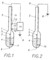
- the hypsometer consists of a boiling vessel 1, e.g. made of glass, which has a vessel flask 2 and a vessel neck 3 which adjoins this and is open at the top.
- the vial flask 2 contains the measuring liquid 4, e.g. Water or methanol, and a temperature sensor 5, preferably in the form of an electrical thermocouple, which measures the boiling point temperature in the vapor space above the liquid level and from which a discharge line 6 leads to the outside.
- the vessel piston 2 also contains an electrical heating resistor 7 of a conventional type that is immersed in the measuring liquid 4 and to which the heating energy is supplied from a battery 8 via a feed line 9.
- an electrical heating resistor 7 of a conventional type that is immersed in the measuring liquid 4 and to which the heating energy is supplied from a battery 8 via a feed line 9.
- a temperature filler 10 or 11 is arranged at each of these measuring points and is connected to a heating controller 14 via a signal line 12 or 13. This regulates the heating power supplied to the heating resistor 7 in such a way that the temperature difference between the two measuring points is kept at a specific setpoint of, for example, 1 ° C.
- a thermistor 15 with a negative temperature coefficient is provided instead of a conventional heating resistor (7 in FIG. 1), which is fed directly from the battery 8 via the feed line 9.
- the control circuit shown in FIG. 1 with parts 10 to 14 is omitted in the embodiment according to FIG. 2.
Landscapes
- Physics & Mathematics (AREA)
- General Physics & Mathematics (AREA)
- Engineering & Computer Science (AREA)
- Automation & Control Theory (AREA)
- Remote Sensing (AREA)
- Control Of Temperature (AREA)
- Investigating Or Analyzing Materials Using Thermal Means (AREA)
- Medicinal Preparation (AREA)
- Measuring Temperature Or Quantity Of Heat (AREA)
- Cookers (AREA)
Applications Claiming Priority (2)
| Application Number | Priority Date | Filing Date | Title |
|---|---|---|---|
| DE3936839A DE3936839C1 (https=) | 1989-11-06 | 1989-11-06 | |
| DE3936839 | 1989-11-06 |
Publications (3)
| Publication Number | Publication Date |
|---|---|
| EP0427662A2 EP0427662A2 (de) | 1991-05-15 |
| EP0427662A3 EP0427662A3 (en) | 1991-09-11 |
| EP0427662B1 true EP0427662B1 (de) | 1994-07-13 |
Family
ID=6392925
Family Applications (1)
| Application Number | Title | Priority Date | Filing Date |
|---|---|---|---|
| EP90810399A Expired - Lifetime EP0427662B1 (de) | 1989-11-06 | 1990-05-30 | Hypsometer mit geregelter Heizung insbesondere für die Verwendung in meteorologischen Radiosonden |
Country Status (7)
| Country | Link |
|---|---|
| US (1) | US5048337A (https=) |
| EP (1) | EP0427662B1 (https=) |
| JP (1) | JPH03167420A (https=) |
| AT (1) | ATE108550T1 (https=) |
| CA (1) | CA2018342C (https=) |
| DE (2) | DE3936839C1 (https=) |
| FI (1) | FI100738B (https=) |
Families Citing this family (2)
| Publication number | Priority date | Publication date | Assignee | Title |
|---|---|---|---|---|
| US6530280B2 (en) * | 2001-03-26 | 2003-03-11 | George Schmermund | Hypsometer |
| CN108332898B (zh) * | 2018-04-17 | 2023-05-09 | 南京信息工程大学 | 一种复合量程气压传感器和高精度探空气压测量装置 |
Family Cites Families (4)
| Publication number | Priority date | Publication date | Assignee | Title |
|---|---|---|---|---|
| US2832219A (en) * | 1955-06-02 | 1958-04-29 | Victory Engineering Corp | Hypsometers |
| US2901909A (en) * | 1957-06-14 | 1959-09-01 | Photographic Survey Corp Ltd | Altitude sensing device |
| US3276262A (en) * | 1964-07-21 | 1966-10-04 | Victory Engineering Corp | Long operating hypsometer structure |
| US4388829A (en) * | 1981-10-05 | 1983-06-21 | Canadian Patents & Development Limited | Evaporation type barometer |
-
1989
- 1989-11-06 DE DE3936839A patent/DE3936839C1/de not_active Expired - Fee Related
-
1990
- 1990-05-30 EP EP90810399A patent/EP0427662B1/de not_active Expired - Lifetime
- 1990-05-30 AT AT90810399T patent/ATE108550T1/de not_active IP Right Cessation
- 1990-05-30 DE DE59006420T patent/DE59006420D1/de not_active Expired - Fee Related
- 1990-06-05 CA CA002018342A patent/CA2018342C/en not_active Expired - Fee Related
- 1990-06-07 US US07/534,427 patent/US5048337A/en not_active Expired - Fee Related
- 1990-06-28 JP JP2171314A patent/JPH03167420A/ja active Pending
- 1990-07-18 FI FI903636A patent/FI100738B/fi not_active IP Right Cessation
Also Published As
| Publication number | Publication date |
|---|---|
| ATE108550T1 (de) | 1994-07-15 |
| US5048337A (en) | 1991-09-17 |
| FI100738B (fi) | 1998-02-13 |
| CA2018342A1 (en) | 1991-05-06 |
| EP0427662A2 (de) | 1991-05-15 |
| JPH03167420A (ja) | 1991-07-19 |
| CA2018342C (en) | 1996-10-29 |
| FI903636A0 (fi) | 1990-07-18 |
| EP0427662A3 (en) | 1991-09-11 |
| DE3936839C1 (https=) | 1990-05-23 |
| DE59006420D1 (de) | 1994-08-18 |
Similar Documents
| Publication | Publication Date | Title |
|---|---|---|
| DE69723622T2 (de) | Infrarote Temperaturerfassung für Trommeltrocknersteuerung | |
| DE3818321C2 (https=) | ||
| DE69313507T2 (de) | Vorrichtung zur Messung der Feuchtigkeit, insbesondere in Nahrungsmittelöfen | |
| CH637203A5 (de) | Ventil fuer kaeltemittelverdampfer. | |
| DE2744878C3 (de) | Hochfrequenz-Ofen | |
| DE2511592C2 (de) | Gerät für thermoanalytische Untersuchungen | |
| DE3413535C1 (de) | Messvorrichtung zum Feststellen eines Fluessigkeitsanteils im Kaeltemittel | |
| DE102008051364A1 (de) | Rotationsverdampfer | |
| DE3333907C2 (https=) | ||
| DE3529956A1 (de) | Verfahren und vorrichtung zum destillieren, abdestillieren und rektifizieren von fluessigkeiten unter vakuum, insbesondere loesungsmitteln, vornehmlich im labor- u. technikumsbetrieb | |
| DE2504659A1 (de) | Verfahren zur kuehlung eines polymerisationsreaktors | |
| CH636430A5 (de) | Ventil fuer kaelteanlagen. | |
| EP0427662B1 (de) | Hypsometer mit geregelter Heizung insbesondere für die Verwendung in meteorologischen Radiosonden | |
| DE1055018B (de) | Verfahren zur Regelung einer Kaeltemaschine und dafuer geeignete Kaeltemaschine | |
| DE69317115T2 (de) | Verfahren zur dynamischen Kontrolle der Eisbildung an einem Kühlschrankverdampfer und Kühlschrank in dem das Verfahren angewandt ist | |
| DE3942664C2 (https=) | ||
| EP0482482B1 (de) | Vorrichtung zur Messung des Wasserdampfpartialdrucks | |
| DE19957309C2 (de) | Rechnerunterstütztes Kalibrierverfahren und Vorrichtung zur Verfahrensdurchführung | |
| DE2939355A1 (de) | Verfahren zur niveauerkennung | |
| EP1199015A2 (de) | Dampfgargerät mit einer kalibrierungslosen Sollsiedetemperatur | |
| EP2013545B1 (de) | Verfahren und vorrichtung zur feuchteregelung in einer klimakammer | |
| DE1501168A1 (de) | Regeleinrichtung zur Aufrechterhaltung einer konstanten Kuehlkapazitaet eines Kuehlmittelstroms | |
| DE10114684C2 (de) | Verfahren zur Feuchteerzeugung in einem Brutschrank | |
| DE3343072C2 (https=) | ||
| DE2538225C3 (de) | Tauspiegelhygrometer |
Legal Events
| Date | Code | Title | Description |
|---|---|---|---|
| PUAI | Public reference made under article 153(3) epc to a published international application that has entered the european phase |
Free format text: ORIGINAL CODE: 0009012 |
|
| AK | Designated contracting states |
Kind code of ref document: A2 Designated state(s): AT BE CH DE DK ES FR GB GR IT LI LU NL SE |
|
| PUAL | Search report despatched |
Free format text: ORIGINAL CODE: 0009013 |
|
| AK | Designated contracting states |
Kind code of ref document: A3 Designated state(s): AT BE CH DE DK ES FR GB GR IT LI LU NL SE |
|
| 17P | Request for examination filed |
Effective date: 19911024 |
|
| 17Q | First examination report despatched |
Effective date: 19921222 |
|
| GRAA | (expected) grant |
Free format text: ORIGINAL CODE: 0009210 |
|
| AK | Designated contracting states |
Kind code of ref document: B1 Designated state(s): AT BE CH DE DK ES FR GB GR IT LI LU NL SE |
|
| PG25 | Lapsed in a contracting state [announced via postgrant information from national office to epo] |
Ref country code: IT Free format text: LAPSE BECAUSE OF FAILURE TO SUBMIT A TRANSLATION OF THE DESCRIPTION OR TO PAY THE FEE WITHIN THE PRE;WARNING: LAPSES OF ITALIAN PATENTS WITH EFFECTIVE DATE BEFORE 2007 MAY HAVE OCCURRED AT ANY TIME BEFORE 2007. THE CORRECT EFFECTIVE DATE MAY BE DIFFERENT FROM THE ONE RECORDED.SCRIBED TIME-LIMIT Effective date: 19940713 Ref country code: BE Effective date: 19940713 Ref country code: DK Effective date: 19940713 Ref country code: GR Free format text: LAPSE BECAUSE OF FAILURE TO SUBMIT A TRANSLATION OF THE DESCRIPTION OR TO PAY THE FEE WITHIN THE PRESCRIBED TIME-LIMIT Effective date: 19940713 Ref country code: ES Free format text: THE PATENT HAS BEEN ANNULLED BY A DECISION OF A NATIONAL AUTHORITY Effective date: 19940713 Ref country code: NL Effective date: 19940713 |
|
| REF | Corresponds to: |
Ref document number: 108550 Country of ref document: AT Date of ref document: 19940715 Kind code of ref document: T |
|
| GBT | Gb: translation of ep patent filed (gb section 77(6)(a)/1977) |
Effective date: 19940711 |
|
| REF | Corresponds to: |
Ref document number: 59006420 Country of ref document: DE Date of ref document: 19940818 |
|
| ET | Fr: translation filed | ||
| PG25 | Lapsed in a contracting state [announced via postgrant information from national office to epo] |
Ref country code: SE Effective date: 19941013 |
|
| NLV1 | Nl: lapsed or annulled due to failure to fulfill the requirements of art. 29p and 29m of the patents act | ||
| PLBE | No opposition filed within time limit |
Free format text: ORIGINAL CODE: 0009261 |
|
| STAA | Information on the status of an ep patent application or granted ep patent |
Free format text: STATUS: NO OPPOSITION FILED WITHIN TIME LIMIT |
|
| 26N | No opposition filed | ||
| PGFP | Annual fee paid to national office [announced via postgrant information from national office to epo] |
Ref country code: FR Payment date: 19980408 Year of fee payment: 9 |
|
| PGFP | Annual fee paid to national office [announced via postgrant information from national office to epo] |
Ref country code: AT Payment date: 19980415 Year of fee payment: 9 |
|
| PGFP | Annual fee paid to national office [announced via postgrant information from national office to epo] |
Ref country code: GB Payment date: 19980417 Year of fee payment: 9 |
|
| PGFP | Annual fee paid to national office [announced via postgrant information from national office to epo] |
Ref country code: CH Payment date: 19980428 Year of fee payment: 9 |
|
| PGFP | Annual fee paid to national office [announced via postgrant information from national office to epo] |
Ref country code: DE Payment date: 19980429 Year of fee payment: 9 Ref country code: LU Payment date: 19980429 Year of fee payment: 9 |
|
| PG25 | Lapsed in a contracting state [announced via postgrant information from national office to epo] |
Ref country code: GB Free format text: LAPSE BECAUSE OF NON-PAYMENT OF DUE FEES Effective date: 19990530 Ref country code: AT Free format text: LAPSE BECAUSE OF NON-PAYMENT OF DUE FEES Effective date: 19990530 Ref country code: LU Free format text: LAPSE BECAUSE OF NON-PAYMENT OF DUE FEES Effective date: 19990530 |
|
| PG25 | Lapsed in a contracting state [announced via postgrant information from national office to epo] |
Ref country code: CH Free format text: LAPSE BECAUSE OF NON-PAYMENT OF DUE FEES Effective date: 19990531 Ref country code: LI Free format text: LAPSE BECAUSE OF NON-PAYMENT OF DUE FEES Effective date: 19990531 |
|
| REG | Reference to a national code |
Ref country code: CH Ref legal event code: PL |
|
| GBPC | Gb: european patent ceased through non-payment of renewal fee |
Effective date: 19990530 |
|
| PG25 | Lapsed in a contracting state [announced via postgrant information from national office to epo] |
Ref country code: FR Free format text: LAPSE BECAUSE OF NON-PAYMENT OF DUE FEES Effective date: 20000131 |
|
| PG25 | Lapsed in a contracting state [announced via postgrant information from national office to epo] |
Ref country code: DE Free format text: LAPSE BECAUSE OF NON-PAYMENT OF DUE FEES Effective date: 20000301 |
|
| REG | Reference to a national code |
Ref country code: FR Ref legal event code: ST |