EP0426449A2 - Water cooled instrument for measuring uniformity of tire - Google Patents
Water cooled instrument for measuring uniformity of tire Download PDFInfo
- Publication number
- EP0426449A2 EP0426449A2 EP90311921A EP90311921A EP0426449A2 EP 0426449 A2 EP0426449 A2 EP 0426449A2 EP 90311921 A EP90311921 A EP 90311921A EP 90311921 A EP90311921 A EP 90311921A EP 0426449 A2 EP0426449 A2 EP 0426449A2
- Authority
- EP
- European Patent Office
- Prior art keywords
- tire
- holder
- spindle
- drum
- cooling water
- Prior art date
- Legal status (The legal status is an assumption and is not a legal conclusion. Google has not performed a legal analysis and makes no representation as to the accuracy of the status listed.)
- Granted
Links
Images




Classifications
-
- G—PHYSICS
- G01—MEASURING; TESTING
- G01M—TESTING STATIC OR DYNAMIC BALANCE OF MACHINES OR STRUCTURES; TESTING OF STRUCTURES OR APPARATUS, NOT OTHERWISE PROVIDED FOR
- G01M17/00—Testing of vehicles
- G01M17/007—Wheeled or endless-tracked vehicles
- G01M17/02—Tyres
- G01M17/022—Tyres the tyre co-operating with rotatable rolls
-
- F—MECHANICAL ENGINEERING; LIGHTING; HEATING; WEAPONS; BLASTING
- F16—ENGINEERING ELEMENTS AND UNITS; GENERAL MEASURES FOR PRODUCING AND MAINTAINING EFFECTIVE FUNCTIONING OF MACHINES OR INSTALLATIONS; THERMAL INSULATION IN GENERAL
- F16C—SHAFTS; FLEXIBLE SHAFTS; ELEMENTS OR CRANKSHAFT MECHANISMS; ROTARY BODIES OTHER THAN GEARING ELEMENTS; BEARINGS
- F16C37/00—Cooling of bearings
- F16C37/007—Cooling of bearings of rolling bearings
Definitions
- This invention relates to an instrument for measuring uniformity of a tire.
- An instrument for measuring uniformity of a tire which includes a spindle to which a tire is to be connected concentrically, a holder for supporting the spindle by way of a bearing thereon; and a drum which is driven to rotate around an axis parallel to the spindle and wherein a detector for measuring uniformity of the tire which is pressed against and rotated by the drum is held on the holder.
- Such conventional instrument is disadvantageous in that, when a tire is to be rotated at a high speed to measure uniformity thereof, since also the speed of rotation of the spindle is high, a temperature drift often takes place in the detector due to generation of heat at the bearing which supports the spindle thereon. The temperature has a bad influence on accuracy in measurement.
- an instrument for measuring uniformity of a tire which comprises a spindle to which a tire is removably fixed for coaxial integral rotation, a holder, bearing means for supporting then spindle for rotation around an axis on the holder a drum supported for rotation around a fixed axis parallel to the axis of the spindle, means for driving the drum to rotate, means for moving the the holder in a direction perpendicular to the axis of the spindle until a tire connected to the spindle is contacted with the drum to allow the tire to be rotated by the drum when the drum is driven to rotate, and a detector held on the holder for measuring uniformity of a tire fixed to the spindle when the tire is rotated by the drum the holder having a cooling water passage formed therein in the proximity of the bearing means for circulating cooling water therealong.
- the bearing means which generates heat upon rotation of the spindle is cooled by cooling water which is circulated in the cooling water passage formed in the holder. Consequently, a possible temperature drift of the detector by heat generation of the bearing means is moderated or eliminated, and accordingly, a high degree of accuracy in measurement of uniformity of a tire is assured.
- the measuring apparatus includes a carriage 2 for moving a tire 1 in its diametrical direction (leftward and rightward directions in FIGS. 4 and 5).
- the tire 1 is removably mounted on the carriage 2 for rotation around the center of a rotary shaft of the carriage 2, and a screw shaft 3 is connected to an end of the carriage 2.
- the screw shaft 3 is supported on a stationary case 4 by way of a screwnut not shown such that an axial direction thereof coincides with a direction of movement of the tire 1.
- a guide 6 for guiding the carriage 2 in Its moving direction is mounted on a stationary member such as a frame not shown.
- the measuring apparatus further includes a drum 7.
- the drum 7 is supported for rotation on the stationary member by way of a support member 8, and an axis of rotation thereof extends in parallel to the axis of rotation of the tire 1.
- Rotating power is transmitted from an AC motor 11 to a rotary shaft 9 of the drum 7 by way of a belt-and-pully transmission mechanism 10. Consequently, if the tire 1 is pressed against the drum 7, the tire 1 is rotated by the drum 7.
- the tire 1 is mounted on the carriage 2 by way of a holder 12, a bearing 13, a spindle 14, detectors 15 and so forth.
- the tire 1 is incorporated in the rim 29 which is attached to a flange portion 27 of the spindle 14 by means of bolts through an adapter 28.
- the bolder 12 is disposed coaxially with the tire 1 and is principally formed from an outer tube member 16 and an inner tube member 17 fitted in the outer tube member 16.
- the outer tube member 16 is mounted at an end thereof on an end face of the carriage 2 remote from the tire 1 by way of suitable mounting means.
- a flange 18 is formed on the inner tube member 17 in an opposing relationship to the other end of the outer tube member 16.
- An annular recess 19 is defined between the flange 18 of the inner tube member 17 and the opposing end face of the outer tube member 16 remote from the carriage 2, and the detectors 15 are fitted in the annular recess 19.
- a seal 34 is interposed between the outer tube member 16 and the inner tube member 17.
- an annular cap 35 is mounted at an end (right end in FIG. 1) of the inner tube member 17, and another seal 36 is interposed between the annular cap 35 and the inner tube member 17.
- the detectors 15 are held between the outer tube member 16 and the flange 18, and a tie rod 20 extends through each of the detectors 15.
- Each of such tie rods 20 has a pair of male thread portions 21 and 22 formed at the opposite ends thereof and extends through a center bore 23 of a corresponding detector 15. and the male thread portion 21 at one end thereof is positioned in a corresponding one of recesses 25 formed at an end of the outer tube member 16 while the male thread portion 22 on the other end is screwed in a female thread 24 formed in the flange 18.
- a nut 26 is received in each of the recesses 25 and screwed on the male thread portion 21 of the corresponding tie rod 21.
- each of the nuts 26 has four recesses 33 formed on an end face thereof for engaging with a tool to operate the nut 26. It is to be noted that, in the present embodiment, each of the detectors 15 is a load cell, and a preload is applied to each of the detectors 15 by tightening the nut 26 for the detector 25.
- the spindle 14 is supported on an inner periphery of the inner tube member 17 by way of a pair of bearings 13 disposed in a spaced relationship in the axial direction.
- each of the bearings 13 is a double row tapered roller bearing.
- a cylindrical spacer 37 is fitted around the spindle 14 between the bearings 13 in the axial direction.
- a pair of passages 30 for cooling water are formed in the inner tube member 17 in the proximity of the bearings 13.
- the passages 30 extend in the axial direction and are disposed at diametrically symmetrical positions with respect to the spindle 14.
- Each of the passages 30 is opened at an end thereof to an end (right end in FIG. 1) of the holder 12. and a female thread 31 is formed in each of the passages 30 adjacent the opening.
- a pipe is removably screwed in the female thread 31 of each of the passages 30 to connect the passage 30 to a cooling water supply source not shown.
- the other end of each of the passages 30 is communicated with the other passage 30 by way of an annular chamber 32 formed in the holder 32.
- cooling water from the cooling water supply source is admitted into one of the passages 30 (the left-hand side one of the openings in FIG. 2) by way of the opening, passes through the one passage 30 and the annular chamber 32 and then through the other passage 30 and flows out from the opening of the other passage 30. While cooling water circulates in this manner, it cools the holder 12 and the bearings 13 in the holder 12.
- the AC servomotor 5 is controlled by a sequencer 50 by way of a driver 51.
- a plurality of charge amplifiers 39 are connected to the sequencer 50, and the detectors 15 are individually connected to the charge amplifiers 39.
- the charge amplifiers 39 are also connected to an operating unit 40 which is in turn connected to a display unit 42.
- the charge amplifiers 39 are further connected individually to buffer amplifiers 52 which are connected to a digital display unit 53.
- the detectors 15 detect variation components in three directions (an axial direction of the tire 1, a moving direction of the tire 1 by the carriage 2 and a direction perpendicular to the two directions), and results of such detection are transmitted to the operating unit 40 individually by way of the charge amplifiers 39 and analyzed by the operating unit 40, and then displayed on the display unit 42.
- a waveform 41 of FIG. 6 wherein the axis of ordinate represents a magnitude of a variation and the axis of abscissa represents time shows an exemplary one of such variation components of the three directions.
- Various waveforms shown below the waveform 41 in FIG. 6 indicate results of higher order analyses depending upon harmonic analysis of such variation components and are waveforms of degrees one to ten in harmonic -degree.
- the present invention is not limited to the embodiment described above. and for example, the detectors 15 may each be a strain gage, or the number or shape of the passages 30 for cooling water may be modified.
Landscapes
- Physics & Mathematics (AREA)
- General Physics & Mathematics (AREA)
- Testing Of Balance (AREA)
Abstract
Description
- This invention relates to an instrument for measuring uniformity of a tire.
- An instrument for measuring uniformity of a tire is conventionally known which includes a spindle to which a tire is to be connected concentrically, a holder for supporting the spindle by way of a bearing thereon; and a drum which is driven to rotate around an axis parallel to the spindle and wherein a detector for measuring uniformity of the tire which is pressed against and rotated by the drum is held on the holder.
- Such conventional instrument is disadvantageous in that, when a tire is to be rotated at a high speed to measure uniformity thereof, since also the speed of rotation of the spindle is high, a temperature drift often takes place in the detector due to generation of heat at the bearing which supports the spindle thereon. The temperature has a bad influence on accuracy in measurement.
- It is an object of the present invention to provide a tire uniformity measuring instrument which does not suffer from a temperature drift and assures accurate measurement of uniformity of a tire.
- In order to attain the object, according to the present invention, there is provided an instrument for measuring uniformity of a tire, which comprises a spindle to which a tire is removably fixed for coaxial integral rotation, a holder, bearing means for supporting then spindle for rotation around an axis on the holder a drum supported for rotation around a fixed axis parallel to the axis of the spindle, means for driving the drum to rotate, means for moving the the holder in a direction perpendicular to the axis of the spindle until a tire connected to the spindle is contacted with the drum to allow the tire to be rotated by the drum when the drum is driven to rotate, and a detector held on the holder for measuring uniformity of a tire fixed to the spindle when the tire is rotated by the drum the holder having a cooling water passage formed therein in the proximity of the bearing means for circulating cooling water therealong.
- With the tire uniformity measuring instrument, the bearing means which generates heat upon rotation of the spindle is cooled by cooling water which is circulated in the cooling water passage formed in the holder. Consequently, a possible temperature drift of the detector by heat generation of the bearing means is moderated or eliminated, and accordingly, a high degree of accuracy in measurement of uniformity of a tire is assured.
- The above and other objects, features and advantages of the present invention will become apparent from the following description and the appended claims, taken in conjunction with the accompanying drawings.
-
- FIG. 1 is a side elevational sectional view of part of an instrument for measuring uniformity of a tire showing a preferred embodiment of the present invention, an upper half of FIG. 1 showing a section taken along line A-A of FIG. 2 while a lower half shows a side elevation;
- FIG. 2 is a front elevational sectional view wherein a left-hand side half shows a section taken along line B-B of FIG. 1 and a right-hand side half is a ylew as viewed in the direction indicated by an arrow mark C in FIG. 1;
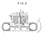
- FIG. 3 is a horizontal sectional view showing, in a reduced scale, general construction of part of the measuring instrument of FIG. 1;
- FIG. 4 is a plan view showing, in a further reduced scale, the entire measuring instrument of FIG. 1;
- FIG. 5 is a side elevational view of the measuring instrument shown in FIG. 4; and
- FIG. 6 is a graph showing exemplary waveforms obtained by the measuring instrument.
- Referring first to FIGS. 4 and 5, there is shown an entire apparatus for measuring uniformity of a tire to which the present invention is applied. The measuring apparatus includes a
carriage 2 for moving a tire 1 in its diametrical direction (leftward and rightward directions in FIGS. 4 and 5). The tire 1 is removably mounted on thecarriage 2 for rotation around the center of a rotary shaft of thecarriage 2, and ascrew shaft 3 is connected to an end of thecarriage 2. Thescrew shaft 3 is supported on astationary case 4 by way of a screwnut not shown such that an axial direction thereof coincides with a direction of movement of the tire 1. As the screw nut is driven to rotate by anAC servomotor 5, thescrew shaft 3 is moved in an axial direction so that the tire 1 mounted on thecarriage 2 is moved in its diametrical direction. It is to be noted that aguide 6 for guiding thecarriage 2 in Its moving direction is mounted on a stationary member such as a frame not shown. - The measuring apparatus further includes a
drum 7. Thedrum 7 is supported for rotation on the stationary member by way of asupport member 8, and an axis of rotation thereof extends in parallel to the axis of rotation of the tire 1. Rotating power is transmitted from an AC motor 11 to arotary shaft 9 of thedrum 7 by way of a belt-and-pully transmission mechanism 10. Consequently, if the tire 1 is pressed against thedrum 7, the tire 1 is rotated by thedrum 7. - Referring now to FIGS. 1 to 3, the tire 1 is mounted on the
carriage 2 by way of aholder 12, abearing 13, aspindle 14,detectors 15 and so forth. The tire 1 is incorporated in therim 29 which is attached to aflange portion 27 of thespindle 14 by means of bolts through anadapter 28. - In particular, the
bolder 12 is disposed coaxially with the tire 1 and is principally formed from anouter tube member 16 and aninner tube member 17 fitted in theouter tube member 16. Theouter tube member 16 is mounted at an end thereof on an end face of thecarriage 2 remote from the tire 1 by way of suitable mounting means. Meanwhile, aflange 18 is formed on theinner tube member 17 in an opposing relationship to the other end of theouter tube member 16. Anannular recess 19 is defined between theflange 18 of theinner tube member 17 and the opposing end face of theouter tube member 16 remote from thecarriage 2, and thedetectors 15 are fitted in theannular recess 19. A seal 34 is interposed between theouter tube member 16 and theinner tube member 17. Further, anannular cap 35 is mounted at an end (right end in FIG. 1) of theinner tube member 17, and anotherseal 36 is interposed between theannular cap 35 and theinner tube member 17. - The
detectors 15 are held between theouter tube member 16 and theflange 18, and atie rod 20 extends through each of thedetectors 15. Each ofsuch tie rods 20 has a pair ofmale thread portions 21 and 22 formed at the opposite ends thereof and extends through acenter bore 23 of acorresponding detector 15. and the male thread portion 21 at one end thereof is positioned in a corresponding one ofrecesses 25 formed at an end of theouter tube member 16 while themale thread portion 22 on the other end is screwed in afemale thread 24 formed in theflange 18. Anut 26 is received in each of therecesses 25 and screwed on the male thread portion 21 of the corresponding tie rod 21. Each of thenuts 26 has fourrecesses 33 formed on an end face thereof for engaging with a tool to operate thenut 26. It is to be noted that, in the present embodiment, each of thedetectors 15 is a load cell, and a preload is applied to each of thedetectors 15 by tightening thenut 26 for thedetector 25. - The
spindle 14 is supported on an inner periphery of theinner tube member 17 by way of a pair ofbearings 13 disposed in a spaced relationship in the axial direction. Here, each of thebearings 13 is a double row tapered roller bearing. Acylindrical spacer 37 is fitted around thespindle 14 between thebearings 13 in the axial direction. - A pair of
passages 30 for cooling water are formed in theinner tube member 17 in the proximity of thebearings 13. Thepassages 30 extend in the axial direction and are disposed at diametrically symmetrical positions with respect to thespindle 14. Each of thepassages 30 is opened at an end thereof to an end (right end in FIG. 1) of theholder 12. and afemale thread 31 is formed in each of thepassages 30 adjacent the opening. Though not shown, a pipe is removably screwed in thefemale thread 31 of each of thepassages 30 to connect thepassage 30 to a cooling water supply source not shown. The other end of each of thepassages 30 is communicated with theother passage 30 by way of anannular chamber 32 formed in theholder 32. Thus, cooling water from the cooling water supply source is admitted into one of the passages 30 (the left-hand side one of the openings in FIG. 2) by way of the opening, passes through the onepassage 30 and theannular chamber 32 and then through theother passage 30 and flows out from the opening of theother passage 30. While cooling water circulates in this manner, it cools theholder 12 and thebearings 13 in theholder 12. - Referring back to FIG. 5, the
AC servomotor 5 is controlled by asequencer 50 by way of adriver 51. A plurality ofcharge amplifiers 39 are connected to thesequencer 50, and thedetectors 15 are individually connected to thecharge amplifiers 39. Thecharge amplifiers 39 are also connected to anoperating unit 40 which is in turn connected to a display unit 42. Thecharge amplifiers 39 are further connected individually tobuffer amplifiers 52 which are connected to adigital display unit 53. - Referring to FIGS. 1 to 5, when uniformity of a tire 1 is to be measured by the measuring instrument. first the tire 1 is moved in a diametrical direction, that is, in a direction perpendicular to the axis of rotation of the tire 1 and hence of the
spindle 14 by thecarriage 2 until it is pressed against thedrum 7 as seen in FIG. 1, and then thedrum 7 is driven to rotate by the AC motor 11. Consequently, the tire 1 is rotated by thedrum 7. Upon such rotation of the tire 1, also thespindle 14 supported on theholder 12 by way of thebearings 13 is rotated by the tire 1. Accordingly, if the tire 1 has some non-uniformity in thickness of rubber, for example, at a tread portion thereof, then such non-uniformity is measured as a variation in load by thedetectors 15. - In the present embodiment. the
detectors 15 detect variation components in three directions (an axial direction of the tire 1, a moving direction of the tire 1 by thecarriage 2 and a direction perpendicular to the two directions), and results of such detection are transmitted to the operatingunit 40 individually by way of thecharge amplifiers 39 and analyzed by the operatingunit 40, and then displayed on the display unit 42. Awaveform 41 of FIG. 6 wherein the axis of ordinate represents a magnitude of a variation and the axis of abscissa represents time shows an exemplary one of such variation components of the three directions. Various waveforms shown below thewaveform 41 in FIG. 6 indicate results of higher order analyses depending upon harmonic analysis of such variation components and are waveforms of degrees one to ten in harmonic -degree. - With the measuring instrument described above, If the supporting rigidity of the
spindle 14 is low, then the measurement accuracy is low, and accordingly, if the dimension (L) shown in FIG. 3 is decreased as small as possible in order to position thedetectors 15 as near as possible to the tire 1, then the influence of the supporting rigidity is decreased as much. Further, while a single row tapered roller bearing is normally employed forsuch bearings 13, a double row tapered roller bearing is employed for thebearings 13 in the present embodiment in order to raise the supporting rigidity. Consequently, accurate measurement is assured with the measuring instrument of the present embodiment. - It is to be noted that the natural frequency of the measuring system can be raised by such improvement in supporting rigidity of the
spindle 14 and the arrangement of thedetectors 15 In the proximity of the tire 1. Consequently, when a harmonic analysis is to be made, a maximum rotational speed nMAX (rpm) of the tire 1 is increased to make an analysis in high harmonic degree accurate because, where a harmonic degree is represented by H, a tire rotational speed corresponding to a harmonic degree is represented by n (rpm), and a natural frequency of the measuring system is represented by τ (Hz), the maximum rotational speed nMAX (rpm) is represented by
H · n =
Then, the influence of heat generation at thebearings 13 upon accuracy in measurement of thedetectors 15 is cancel led by cooling water flowing in thepassages 30, and no or little temperature drift will take place in thedetectors 15. Particularly in the present embodiment, since a preload is applied to thedetectors 15 by means of thetie rods 20 extending in the axial direction of the tire 1, thermal deformation of thetie rods 20 in the axial direction can be prevented, and consequently, a possible temperature drift upon detection of uniformity of the tire 1 in the axial direction can be prevented effectively. - It is to be noted that the present invention is not limited to the embodiment described above. and for example, the
detectors 15 may each be a strain gage, or the number or shape of thepassages 30 for cooling water may be modified. - Having now fully described the invention, it will be apparent to one of ordinary skill in the art that many changes and modifications can be made thereto without departing from the spirit and scope of the invention as set forth herein.
Claims (5)
Applications Claiming Priority (2)
| Application Number | Priority Date | Filing Date | Title |
|---|---|---|---|
| JP128104/89 | 1989-10-31 | ||
| JP1989128104U JPH0645239Y2 (en) | 1989-10-31 | 1989-10-31 | Tire uniformity measuring device |
Publications (3)
| Publication Number | Publication Date |
|---|---|
| EP0426449A2 true EP0426449A2 (en) | 1991-05-08 |
| EP0426449A3 EP0426449A3 (en) | 1992-09-02 |
| EP0426449B1 EP0426449B1 (en) | 1994-04-27 |
Family
ID=14976492
Family Applications (1)
| Application Number | Title | Priority Date | Filing Date |
|---|---|---|---|
| EP90311921A Expired - Lifetime EP0426449B1 (en) | 1989-10-31 | 1990-10-31 | Water cooled instrument for measuring uniformity of tire |
Country Status (4)
| Country | Link |
|---|---|
| US (1) | US5103669A (en) |
| EP (1) | EP0426449B1 (en) |
| JP (1) | JPH0645239Y2 (en) |
| DE (1) | DE69008484T2 (en) |
Cited By (1)
| Publication number | Priority date | Publication date | Assignee | Title |
|---|---|---|---|---|
| EP2642270A3 (en) * | 2012-03-22 | 2017-08-23 | Kabushiki Kaisha Kobe Seiko Sho (Kobe Steel, Ltd.) | Multi-component force measurement spindle unit of tire testing machine |
Families Citing this family (7)
| Publication number | Priority date | Publication date | Assignee | Title |
|---|---|---|---|---|
| GB9915052D0 (en) * | 1999-06-28 | 1999-08-25 | Lonsdale Anthony | Apparatus and method for detecting the condition of an item |
| US6651716B1 (en) | 2000-02-23 | 2003-11-25 | The Goodyear Tire & Rubber Company | Method and tire adapted for post cure tire uniformity correction |
| US6673184B1 (en) | 2000-02-23 | 2004-01-06 | The Goodyear Tire & Rubber Company | Tire and method for correcting tire uniformity thereof |
| US6257956B1 (en) | 2000-03-06 | 2001-07-10 | The Goodyear Tire & Rubber Company | Method to identify and remove machine contributions from tire uniformity measurements |
| US6740280B1 (en) | 2000-04-10 | 2004-05-25 | The Goodyear Tire & Rubber Company | Tire construction method for improving tire uniformity |
| KR100998058B1 (en) | 2008-07-03 | 2010-12-03 | 한국타이어 주식회사 | Tire Uniformity Analysis System and Analysis Method |
| JP5784533B2 (en) * | 2012-03-22 | 2015-09-24 | 株式会社神戸製鋼所 | Multi-force measuring spindle unit for tire testing machine |
Family Cites Families (6)
| Publication number | Priority date | Publication date | Assignee | Title |
|---|---|---|---|---|
| US4171641A (en) * | 1978-07-13 | 1979-10-23 | The B. F. Goodrich Company | Method for measuring uniformity of tires |
| US4541738A (en) * | 1983-08-11 | 1985-09-17 | The Timken Company | Refrigerant cooled tapered roller bearing assembly |
| JPH0446197Y2 (en) * | 1987-05-25 | 1992-10-29 | ||
| JPH01192532A (en) * | 1988-01-29 | 1989-08-02 | Mitsubishi Heavy Ind Ltd | Automatic rim replacing apparatus for tire uniformity machine |
| US4852398A (en) * | 1988-03-09 | 1989-08-01 | Eagle-Picher Industries, Inc. | Tire testing machine having adjustable bead width |
| US4948269A (en) * | 1989-07-11 | 1990-08-14 | Hamilton James T | Bearing temperature regulation and lubrication system |
-
1989
- 1989-10-31 JP JP1989128104U patent/JPH0645239Y2/en not_active Expired - Lifetime
-
1990
- 1990-10-31 US US07/606,190 patent/US5103669A/en not_active Expired - Lifetime
- 1990-10-31 EP EP90311921A patent/EP0426449B1/en not_active Expired - Lifetime
- 1990-10-31 DE DE69008484T patent/DE69008484T2/en not_active Expired - Fee Related
Cited By (1)
| Publication number | Priority date | Publication date | Assignee | Title |
|---|---|---|---|---|
| EP2642270A3 (en) * | 2012-03-22 | 2017-08-23 | Kabushiki Kaisha Kobe Seiko Sho (Kobe Steel, Ltd.) | Multi-component force measurement spindle unit of tire testing machine |
Also Published As
| Publication number | Publication date |
|---|---|
| DE69008484D1 (en) | 1994-06-01 |
| DE69008484T2 (en) | 1994-08-25 |
| JPH0645239Y2 (en) | 1994-11-16 |
| EP0426449A3 (en) | 1992-09-02 |
| JPH0365949U (en) | 1991-06-26 |
| US5103669A (en) | 1992-04-14 |
| EP0426449B1 (en) | 1994-04-27 |
Similar Documents
| Publication | Publication Date | Title |
|---|---|---|
| EP0426449B1 (en) | Water cooled instrument for measuring uniformity of tire | |
| CN102162717A (en) | Device and method for automatically detecting composite errors of spiral inner raceway of ball nut | |
| CN109612369B (en) | Bearing inner and outer ring end face height difference measuring device | |
| CN111474064A (en) | Cable torsion bending tester | |
| US5383355A (en) | Gas turbine engine inspection system | |
| CN218156657U (en) | Wheel hub bearing flange dynamic balance parameter detection subassembly | |
| US5311785A (en) | Probe holder for a rotary scanner | |
| CN207881655U (en) | A kind of integrated correction device | |
| CN217303902U (en) | Detection apparatus for motor positioning accuracy | |
| CN211147563U (en) | Shaft runout amount detection device based on virtual instrument | |
| JPS6037398B2 (en) | Inspection equipment for heat exchanger tubes | |
| CN109029307B (en) | Steel ring detection frock of beating | |
| CN220583642U (en) | Axial force torque instrument device | |
| CN219776958U (en) | Automatic testing device for steering force of forklift | |
| CN116026505B (en) | Device for measuring axial force of motor | |
| CN222589025U (en) | Wireless snap ring type strain type torque sensor and knife handle comprising same | |
| CN223971555U (en) | Straightness detection device of slender pipe type part | |
| CN224262648U (en) | A swing-type circular cast billet curved section surface temperature measuring device | |
| CN216791410U (en) | Automatic pendulum shaft device for optical calibration measurement | |
| CN220650706U (en) | Calibration test equipment for automobile eddy current rotating speed sensor | |
| CN223841107U (en) | Quick alignment of worm wheel processing and worm wheel throat circle radius detection device | |
| CN219140021U (en) | Regulating valve | |
| CN218085716U (en) | High-precision steering angle sensor device for intelligent driving vehicle | |
| CN221225036U (en) | Adjustable horizontal rotary device | |
| CN217620136U (en) | Steam generator pipe orifice centering device |
Legal Events
| Date | Code | Title | Description |
|---|---|---|---|
| PUAI | Public reference made under article 153(3) epc to a published international application that has entered the european phase |
Free format text: ORIGINAL CODE: 0009012 |
|
| 17P | Request for examination filed |
Effective date: 19901106 |
|
| AK | Designated contracting states |
Kind code of ref document: A2 Designated state(s): DE FR GB |
|
| PUAL | Search report despatched |
Free format text: ORIGINAL CODE: 0009013 |
|
| AK | Designated contracting states |
Kind code of ref document: A3 Designated state(s): DE FR GB |
|
| 17Q | First examination report despatched |
Effective date: 19930818 |
|
| GRAA | (expected) grant |
Free format text: ORIGINAL CODE: 0009210 |
|
| AK | Designated contracting states |
Kind code of ref document: B1 Designated state(s): DE FR GB |
|
| ET | Fr: translation filed | ||
| REF | Corresponds to: |
Ref document number: 69008484 Country of ref document: DE Date of ref document: 19940601 |
|
| PLBE | No opposition filed within time limit |
Free format text: ORIGINAL CODE: 0009261 |
|
| STAA | Information on the status of an ep patent application or granted ep patent |
Free format text: STATUS: NO OPPOSITION FILED WITHIN TIME LIMIT |
|
| 26N | No opposition filed | ||
| PGFP | Annual fee paid to national office [announced via postgrant information from national office to epo] |
Ref country code: DE Payment date: 19981106 Year of fee payment: 9 |
|
| PG25 | Lapsed in a contracting state [announced via postgrant information from national office to epo] |
Ref country code: DE Free format text: LAPSE BECAUSE OF NON-PAYMENT OF DUE FEES Effective date: 20000801 |
|
| REG | Reference to a national code |
Ref country code: GB Ref legal event code: IF02 |
|
| PGFP | Annual fee paid to national office [announced via postgrant information from national office to epo] |
Ref country code: FR Payment date: 20021008 Year of fee payment: 13 |
|
| PGFP | Annual fee paid to national office [announced via postgrant information from national office to epo] |
Ref country code: GB Payment date: 20021030 Year of fee payment: 13 |
|
| PG25 | Lapsed in a contracting state [announced via postgrant information from national office to epo] |
Ref country code: GB Free format text: LAPSE BECAUSE OF NON-PAYMENT OF DUE FEES Effective date: 20031031 |
|
| GBPC | Gb: european patent ceased through non-payment of renewal fee |
Effective date: 20031031 |
|
| PG25 | Lapsed in a contracting state [announced via postgrant information from national office to epo] |
Ref country code: FR Free format text: LAPSE BECAUSE OF NON-PAYMENT OF DUE FEES Effective date: 20040630 |
|
| REG | Reference to a national code |
Ref country code: FR Ref legal event code: ST |