EP0425963B1 - Device for conveying blood flow during liver surgery - Google Patents
Device for conveying blood flow during liver surgery Download PDFInfo
- Publication number
- EP0425963B1 EP0425963B1 EP90120227A EP90120227A EP0425963B1 EP 0425963 B1 EP0425963 B1 EP 0425963B1 EP 90120227 A EP90120227 A EP 90120227A EP 90120227 A EP90120227 A EP 90120227A EP 0425963 B1 EP0425963 B1 EP 0425963B1
- Authority
- EP
- European Patent Office
- Prior art keywords
- tubular element
- blood flow
- flow during
- holes
- tubular
- Prior art date
- Legal status (The legal status is an assumption and is not a legal conclusion. Google has not performed a legal analysis and makes no representation as to the accuracy of the status listed.)
- Expired - Lifetime
Links
- 210000004185 liver Anatomy 0.000 title claims description 10
- 238000001356 surgical procedure Methods 0.000 title claims description 8
- 230000017531 blood circulation Effects 0.000 title claims description 7
- 239000008280 blood Substances 0.000 claims description 5
- 210000004369 blood Anatomy 0.000 claims description 5
- 230000000747 cardiac effect Effects 0.000 description 4
- 210000002837 heart atrium Anatomy 0.000 description 4
- 238000000034 method Methods 0.000 description 3
- 230000002792 vascular Effects 0.000 description 3
- 210000002620 vena cava superior Anatomy 0.000 description 3
- 230000004087 circulation Effects 0.000 description 2
- 210000004731 jugular vein Anatomy 0.000 description 2
- 239000000463 material Substances 0.000 description 2
- 210000003462 vein Anatomy 0.000 description 2
- 210000001631 vena cava inferior Anatomy 0.000 description 2
- 206010020772 Hypertension Diseases 0.000 description 1
- 230000000740 bleeding effect Effects 0.000 description 1
- 230000002349 favourable effect Effects 0.000 description 1
- 230000002440 hepatic effect Effects 0.000 description 1
- 208000014674 injury Diseases 0.000 description 1
- 238000003780 insertion Methods 0.000 description 1
- 230000037431 insertion Effects 0.000 description 1
- 230000000968 intestinal effect Effects 0.000 description 1
- 230000000670 limiting effect Effects 0.000 description 1
- 229920002635 polyurethane Polymers 0.000 description 1
- 239000004814 polyurethane Substances 0.000 description 1
- 210000004258 portal system Anatomy 0.000 description 1
- 230000008733 trauma Effects 0.000 description 1
Images

Classifications
-
- A—HUMAN NECESSITIES
- A61—MEDICAL OR VETERINARY SCIENCE; HYGIENE
- A61M—DEVICES FOR INTRODUCING MEDIA INTO, OR ONTO, THE BODY; DEVICES FOR TRANSDUCING BODY MEDIA OR FOR TAKING MEDIA FROM THE BODY; DEVICES FOR PRODUCING OR ENDING SLEEP OR STUPOR
- A61M25/00—Catheters; Hollow probes
Definitions
- the invention relates to a device for conveying blood flow during liver surgery.
- EP-A-0 212 159 shows a catheter device for blood flow which comprises an elongated tube perforated at one end and connected at another end to a blood circuit.
- a plunger element is also provided which is slidingly movable inside the tube in order to either block or open the perforations in the end of the tube.
- the aim of the present invention is to provide a device for conveying blood flow during liver surgery which allows to eliminate all clinical problems for the patient, which allows the surgeon to operate in the most favorable conditions and has maximum simplicity.
- the proposed aim is achieved by a device for conveying blood flow during liver surgery, according to the invention, as defined in the appended claim 1.
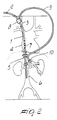
- the reference numeral 1 indicates the first tubular element, made of any polymeric material with a good degree of biocompatibility, such as for example polyurethane, internally provided with the sealingly slidable obturator 2, which is illustrated in figure 1 in the position it assumes during the insertion of the element 1 in the patient's body, whereas in figure 2 it is illustrated in the position it assumes during surgery, as will be better explained hereinafter.
- Said tubular element 1 is adapted to be inserted in the patient's body passing through the right external jugular vein 3, the right cardiac atrium 4 and the superior vena cava 5 to be connected to the inferior vena cava 6 during surgery requiring the removal of the liver, which is indeed interposed between said veins 5 and 6, or the temporary bypassing of the liver vascular system.
- the element 1 is provided, in the wall portion intended to be comprised inside the cardiac atrium 4, with through holes such as 7 which return blood to the heart.
- connection 8 to the second tubular element 9 is provided on said element 1 in such a position as to be external to the body of the patient when the first tubular element 1 is completely inserted; said tubular element 9 is adapted to be connected to the vena portae 10 after defining a path outside the patient's body.
- the constructive details to be observed are constituted by the tapered shape, such as 1a, of the ends of the tubular elements, and by the fact that the continuity of the internal surfaces of the walls of said tubular elements is maintained inside the connection 8 so as to avoid any trauma to the blood which affects them.
- the tubular element 1 is inserted in the right jugular vein 3 through an incision in the patient's neck, with the obturator 2 protruding from the ends 1a, and is then inserted in the right cardiac atrium 4 and in the superior vena cava 5 to be connected to the lower vena cava 6.
- connection 8 has remained external to the patient's body, and the second tubular element 9, after a certain external path, is also inserted in the patient's body and is connected to the vena portae 10.
- the obturator 2 When the entire apparatus is connected by ligature of the tubular elements to the veins, the obturator 2 is retracted until it reaches the position of figure 2, and in this manner the return of venous blood from the lower caval system and from the portal system is re-established even when the liver is removed or the vascular system thereof is bypassed.
- the invention allows, with a very simple device, to maintain high blood flows from the vena portae and from the inferior vena cava to the right cardiac atrium while the liver is bypassed from circulation, so as to clinically protect the patient, and furthermore allows the surgeon to operate with maximum comfort.
- the materials employed, as well as the shapes and dimensions, may be any according to the requirements.
Landscapes
- Health & Medical Sciences (AREA)
- Life Sciences & Earth Sciences (AREA)
- Hematology (AREA)
- Animal Behavior & Ethology (AREA)
- Engineering & Computer Science (AREA)
- Anesthesiology (AREA)
- Biomedical Technology (AREA)
- Heart & Thoracic Surgery (AREA)
- Biophysics (AREA)
- Pulmonology (AREA)
- General Health & Medical Sciences (AREA)
- Public Health (AREA)
- Veterinary Medicine (AREA)
- External Artificial Organs (AREA)
- Surgical Instruments (AREA)
- Infusion, Injection, And Reservoir Apparatuses (AREA)
- Media Introduction/Drainage Providing Device (AREA)
- Measuring Pulse, Heart Rate, Blood Pressure Or Blood Flow (AREA)
Description
- The invention relates to a device for conveying blood flow during liver surgery.
- It is known that surgical operations involving the liver of a patient, both those which provide its removal and those during which it is necessary to temporarily bypass the hepatic vascular system, have numerous problems.
- The technique which entails the clamping of the vena portae and the superior vena cava during surgery causes the unfavorable condition of marked renal and intestinal hypertension with possible severe clinical consequences.
- In order to obviate this situation, attempts have been made to establish an extra-corporeal circulation, but with such methods as to cause hardly negligible technical and logistic problems.
- Another unfavorable circumstance which arises in the known technique resides in the fact that the extensive bleeding produced forces very fast surgical actions on the part of the surgeon and the adoption of auto-transfusion, with all the problems which arise therefrom.
- EP-A-0 212 159 shows a catheter device for blood flow which comprises an elongated tube perforated at one end and connected at another end to a blood circuit. A plunger element is also provided which is slidingly movable inside the tube in order to either block or open the perforations in the end of the tube.
- The aim of the present invention is to provide a device for conveying blood flow during liver surgery which allows to eliminate all clinical problems for the patient, which allows the surgeon to operate in the most favorable conditions and has maximum simplicity.
- The proposed aim is achieved by a device for conveying blood flow during liver surgery, according to the invention, as defined in the appended
claim 1. - Further characteristics and advantages will become apparent from the description of a preferred but not exclusive embodiment of the invention, illustrated only by way of non-limitative example in the accompanying drawings, wherein:
- figure 1 is a partially sectional view of the invention;
- figure 2 is a view of the invention during an application.
- With particular reference to the above figures, the
reference numeral 1 indicates the first tubular element, made of any polymeric material with a good degree of biocompatibility, such as for example polyurethane, internally provided with the sealinglyslidable obturator 2, which is illustrated in figure 1 in the position it assumes during the insertion of theelement 1 in the patient's body, whereas in figure 2 it is illustrated in the position it assumes during surgery, as will be better explained hereinafter. - Said
tubular element 1 is adapted to be inserted in the patient's body passing through the right externaljugular vein 3, the right cardiac atrium 4 and thesuperior vena cava 5 to be connected to theinferior vena cava 6 during surgery requiring the removal of the liver, which is indeed interposed betweensaid veins - The
element 1 is provided, in the wall portion intended to be comprised inside the cardiac atrium 4, with through holes such as 7 which return blood to the heart. - The
connection 8 to the secondtubular element 9 is provided on saidelement 1 in such a position as to be external to the body of the patient when the firsttubular element 1 is completely inserted; saidtubular element 9 is adapted to be connected to thevena portae 10 after defining a path outside the patient's body. - The constructive details to be observed are constituted by the tapered shape, such as 1a, of the ends of the tubular elements, and by the fact that the continuity of the internal surfaces of the walls of said tubular elements is maintained inside the
connection 8 so as to avoid any trauma to the blood which affects them. - The operation of the invention is evident.
- The
tubular element 1 is inserted in the rightjugular vein 3 through an incision in the patient's neck, with theobturator 2 protruding from the ends 1a, and is then inserted in the right cardiac atrium 4 and in thesuperior vena cava 5 to be connected to thelower vena cava 6. - The
connection 8 has remained external to the patient's body, and the secondtubular element 9, after a certain external path, is also inserted in the patient's body and is connected to thevena portae 10. - When the entire apparatus is connected by ligature of the tubular elements to the veins, the
obturator 2 is retracted until it reaches the position of figure 2, and in this manner the return of venous blood from the lower caval system and from the portal system is re-established even when the liver is removed or the vascular system thereof is bypassed. - From what has been described the advantageous characteristics of the invention are evident; the invention allows, with a very simple device, to maintain high blood flows from the vena portae and from the inferior vena cava to the right cardiac atrium while the liver is bypassed from circulation, so as to clinically protect the patient, and furthermore allows the surgeon to operate with maximum comfort.
- In the practical embodiment of the invention, the materials employed, as well as the shapes and dimensions, may be any according to the requirements.
- Where technical features mentioned in any claim are followed by reference signs, those reference signs have been included for the sole purpose of increasing the intelligibility of the claims and accordingly such reference signs do not have any limiting effect on the scope of each element identified by way of example by such reference signs.
Claims (3)
- Device for conveying blood flow during liver surgery, comprising a first tubular element (1) having a first end (1a), a second end, and a middle wall portion between said two ends, through holes (7) for the passage of blood being provided in said first tubular element, the device further comprising an obturator (2) which is sealingly slidable inside said tubular element from said second end between a closed position which blocks said through holes (7) and an open position in which said through holes are open, the device being characterized in that a first end (1a) of said two ends is open and said through holes are provided in said middle wall portion away from said first end, the device further comprising a second tubular element (9) having a first end which is connected by a connector (8) to said first tubular element at a position between said second end of said first tubular element and said through holes, said second tubular element having a second end which is open.
- Device according to claim 1, characterized in that said ends (1a) of the two tubular elements (1,9) are tapered.
- Device according to claims 1 or 2, characterized in that a continuity of the inner surfaces of the walls of the two tubular elements (1,9) is present inside the connection (8) between said tubular elements.
Applications Claiming Priority (2)
| Application Number | Priority Date | Filing Date | Title |
|---|---|---|---|
| IT02220489A IT1236638B (en) | 1989-10-31 | 1989-10-31 | DEVICE FOR THE CONVEYMENT OF BLOOD FLOW IN THE COURSE OF SURGICAL OPERATIONS ON THE LIVER. |
| IT2220489 | 1989-10-31 |
Publications (2)
| Publication Number | Publication Date |
|---|---|
| EP0425963A1 EP0425963A1 (en) | 1991-05-08 |
| EP0425963B1 true EP0425963B1 (en) | 1994-06-15 |
Family
ID=11193007
Family Applications (1)
| Application Number | Title | Priority Date | Filing Date |
|---|---|---|---|
| EP90120227A Expired - Lifetime EP0425963B1 (en) | 1989-10-31 | 1990-10-22 | Device for conveying blood flow during liver surgery |
Country Status (6)
| Country | Link |
|---|---|
| EP (1) | EP0425963B1 (en) |
| JP (1) | JP2972317B2 (en) |
| AU (1) | AU621009B2 (en) |
| CA (1) | CA2028712C (en) |
| DE (2) | DE9014170U1 (en) |
| IT (1) | IT1236638B (en) |
Families Citing this family (1)
| Publication number | Priority date | Publication date | Assignee | Title |
|---|---|---|---|---|
| CN102100570B (en) * | 2011-02-17 | 2012-04-18 | 浙江大学 | Porta hepatis blocking device |
Family Cites Families (6)
| Publication number | Priority date | Publication date | Assignee | Title |
|---|---|---|---|---|
| US3851646A (en) * | 1973-04-13 | 1974-12-03 | Sarns Inc | Connector for open heart surgery |
| IT1197675B (en) * | 1983-07-13 | 1988-12-06 | Ugo Pasqui | CAVAL DRAINAGE CANNULA, FOR THE EXTRA BODY CIRCULATION SYSTEM, EQUIPPED WITH INFLATABLE SEALING SLEEVE |
| US4592754A (en) * | 1983-09-09 | 1986-06-03 | Gupte Pradeep M | Surgical prosthetic vessel graft and catheter combination and method |
| US4680029A (en) * | 1984-02-23 | 1987-07-14 | Sherwood Medical Company | Vena caval catheter |
| DE3523520A1 (en) * | 1985-07-01 | 1987-01-08 | Stoeckert Instr Gmbh | VESSEL CATHETER |
| US4804365A (en) * | 1987-02-13 | 1989-02-14 | C. R. Bard | Vascular cannulae for transfemoral cardiopulmonary bypass and method of use |
-
1989
- 1989-10-31 IT IT02220489A patent/IT1236638B/en active IP Right Grant
-
1990
- 1990-10-11 DE DE9014170U patent/DE9014170U1/en not_active Expired - Lifetime
- 1990-10-22 EP EP90120227A patent/EP0425963B1/en not_active Expired - Lifetime
- 1990-10-22 DE DE69009931T patent/DE69009931T2/en not_active Expired - Fee Related
- 1990-10-26 JP JP2290600A patent/JP2972317B2/en not_active Expired - Lifetime
- 1990-10-29 CA CA002028712A patent/CA2028712C/en not_active Expired - Fee Related
- 1990-10-30 AU AU65629/90A patent/AU621009B2/en not_active Ceased
Also Published As
| Publication number | Publication date |
|---|---|
| JP2972317B2 (en) | 1999-11-08 |
| JPH03155850A (en) | 1991-07-03 |
| DE69009931T2 (en) | 1994-09-22 |
| CA2028712A1 (en) | 1991-05-01 |
| DE69009931D1 (en) | 1994-07-21 |
| EP0425963A1 (en) | 1991-05-08 |
| IT8922204A1 (en) | 1991-05-01 |
| DE9014170U1 (en) | 1991-01-10 |
| AU6562990A (en) | 1991-07-18 |
| IT1236638B (en) | 1993-03-25 |
| IT8922204A0 (en) | 1989-10-31 |
| AU621009B2 (en) | 1992-02-27 |
| CA2028712C (en) | 1999-02-23 |
Similar Documents
| Publication | Publication Date | Title |
|---|---|---|
| JP4681190B2 (en) | Device for controlling extravascular bleeding | |
| US5135474A (en) | Hepatic bypass catheter | |
| US6099506A (en) | Introducer and perfusion cannula | |
| US6086557A (en) | Bifurcated venous cannula | |
| US6599266B2 (en) | Occlusion cannula and methods of use | |
| US6709415B2 (en) | Intraluminal catheter with expandable tubular open-walled element | |
| US6132397A (en) | Integral aortic arch infusion clamp catheter | |
| EP0894507B1 (en) | Balloon Catheter | |
| US8043365B2 (en) | Methods for placement of vascular stent grafts and vascular stents | |
| US6689097B2 (en) | Flow-by channel catheter and method of use | |
| US6464664B1 (en) | Method for using intravascular balloon occlusion device | |
| US20020128598A1 (en) | Blood vessel occlusion device | |
| US20010023357A1 (en) | Arterial occluding cannula and methods of use | |
| EP0159773A1 (en) | Vena caval catheter and tip therefor | |
| CA2647854A1 (en) | Implantable cerebral protection device and methods of use | |
| EP0280225A3 (en) | A vein drain cannula | |
| US20060247575A1 (en) | Balloon cannulae | |
| US11478250B2 (en) | Systems and methods for retrograde perfusion and clearance of emboli | |
| US6068608A (en) | Method of using integral aortic arch infusion clamp | |
| CA2028712C (en) | Device for conveying blood flow during liver surgery | |
| US12042152B2 (en) | Systems and methods for retrograde perfusion and clearance of emboli | |
| Molmenti et al. | Rapid temporary portosystemic bypass | |
| GB2411842A (en) | Balloon obturator for the aorta | |
| Scurr | Transvenous interruption of the inferior vena cava | |
| WO2004016195A2 (en) | Vascular stent grafts |
Legal Events
| Date | Code | Title | Description |
|---|---|---|---|
| PUAI | Public reference made under article 153(3) epc to a published international application that has entered the european phase |
Free format text: ORIGINAL CODE: 0009012 |
|
| AK | Designated contracting states |
Kind code of ref document: A1 Designated state(s): DE FR GB IT |
|
| 17P | Request for examination filed |
Effective date: 19910726 |
|
| RAP1 | Party data changed (applicant data changed or rights of an application transferred) |
Owner name: DIDECO S.R.L. |
|
| 17Q | First examination report despatched |
Effective date: 19921201 |
|
| RAP1 | Party data changed (applicant data changed or rights of an application transferred) |
Owner name: DIDECO S.P.A. |
|
| GRAA | (expected) grant |
Free format text: ORIGINAL CODE: 0009210 |
|
| AK | Designated contracting states |
Kind code of ref document: B1 Designated state(s): DE FR GB IT |
|
| ET | Fr: translation filed | ||
| REF | Corresponds to: |
Ref document number: 69009931 Country of ref document: DE Date of ref document: 19940721 |
|
| ITF | It: translation for a ep patent filed | ||
| PLBE | No opposition filed within time limit |
Free format text: ORIGINAL CODE: 0009261 |
|
| STAA | Information on the status of an ep patent application or granted ep patent |
Free format text: STATUS: NO OPPOSITION FILED WITHIN TIME LIMIT |
|
| 26N | No opposition filed | ||
| PGFP | Annual fee paid to national office [announced via postgrant information from national office to epo] |
Ref country code: GB Payment date: 20011015 Year of fee payment: 12 |
|
| PGFP | Annual fee paid to national office [announced via postgrant information from national office to epo] |
Ref country code: FR Payment date: 20011022 Year of fee payment: 12 |
|
| PGFP | Annual fee paid to national office [announced via postgrant information from national office to epo] |
Ref country code: DE Payment date: 20011231 Year of fee payment: 12 |
|
| REG | Reference to a national code |
Ref country code: GB Ref legal event code: IF02 |
|
| PG25 | Lapsed in a contracting state [announced via postgrant information from national office to epo] |
Ref country code: GB Free format text: LAPSE BECAUSE OF NON-PAYMENT OF DUE FEES Effective date: 20021022 |
|
| PG25 | Lapsed in a contracting state [announced via postgrant information from national office to epo] |
Ref country code: DE Free format text: LAPSE BECAUSE OF NON-PAYMENT OF DUE FEES Effective date: 20030501 |
|
| GBPC | Gb: european patent ceased through non-payment of renewal fee |
Effective date: 20021022 |
|
| PG25 | Lapsed in a contracting state [announced via postgrant information from national office to epo] |
Ref country code: FR Free format text: LAPSE BECAUSE OF NON-PAYMENT OF DUE FEES Effective date: 20030630 |
|
| REG | Reference to a national code |
Ref country code: FR Ref legal event code: ST |
|
| PGFP | Annual fee paid to national office [announced via postgrant information from national office to epo] |
Ref country code: IT Payment date: 20081028 Year of fee payment: 19 |
|
| PG25 | Lapsed in a contracting state [announced via postgrant information from national office to epo] |
Ref country code: IT Free format text: LAPSE BECAUSE OF NON-PAYMENT OF DUE FEES Effective date: 20091022 |