EP0425576B1 - Dynamic seal arrangement for impeller pump - Google Patents
Dynamic seal arrangement for impeller pump Download PDFInfo
- Publication number
- EP0425576B1 EP0425576B1 EP89908956A EP89908956A EP0425576B1 EP 0425576 B1 EP0425576 B1 EP 0425576B1 EP 89908956 A EP89908956 A EP 89908956A EP 89908956 A EP89908956 A EP 89908956A EP 0425576 B1 EP0425576 B1 EP 0425576B1
- Authority
- EP
- European Patent Office
- Prior art keywords
- shaft
- seal
- pump
- seal ring
- fluid
- Prior art date
- Legal status (The legal status is an assumption and is not a legal conclusion. Google has not performed a legal analysis and makes no representation as to the accuracy of the status listed.)
- Expired - Lifetime
Links
- 239000012530 fluid Substances 0.000 claims abstract description 40
- 230000013011 mating Effects 0.000 claims abstract description 31
- 238000007789 sealing Methods 0.000 claims abstract description 19
- 238000005086 pumping Methods 0.000 claims abstract description 12
- 230000003068 static effect Effects 0.000 claims description 3
- 238000000034 method Methods 0.000 claims 1
- 230000020169 heat generation Effects 0.000 abstract description 4
- 210000004907 gland Anatomy 0.000 description 15
- 239000007788 liquid Substances 0.000 description 12
- 238000005299 abrasion Methods 0.000 description 2
- 230000004888 barrier function Effects 0.000 description 2
- 230000000694 effects Effects 0.000 description 2
- 238000013021 overheating Methods 0.000 description 2
- 239000002002 slurry Substances 0.000 description 2
- OKTJSMMVPCPJKN-UHFFFAOYSA-N Carbon Chemical compound [C] OKTJSMMVPCPJKN-UHFFFAOYSA-N 0.000 description 1
- 235000008733 Citrus aurantifolia Nutrition 0.000 description 1
- 229920002449 FKM Polymers 0.000 description 1
- 235000011941 Tilia x europaea Nutrition 0.000 description 1
- 240000008042 Zea mays Species 0.000 description 1
- 235000005824 Zea mays ssp. parviglumis Nutrition 0.000 description 1
- 235000002017 Zea mays subsp mays Nutrition 0.000 description 1
- 239000002253 acid Substances 0.000 description 1
- 229910052799 carbon Inorganic materials 0.000 description 1
- 239000003518 caustics Substances 0.000 description 1
- 238000004140 cleaning Methods 0.000 description 1
- 239000011248 coating agent Substances 0.000 description 1
- 238000000576 coating method Methods 0.000 description 1
- 235000005822 corn Nutrition 0.000 description 1
- 229920001971 elastomer Polymers 0.000 description 1
- 239000000806 elastomer Substances 0.000 description 1
- JBKVHLHDHHXQEQ-UHFFFAOYSA-N epsilon-caprolactam Chemical compound O=C1CCCCCN1 JBKVHLHDHHXQEQ-UHFFFAOYSA-N 0.000 description 1
- 239000004571 lime Substances 0.000 description 1
- 239000011253 protective coating Substances 0.000 description 1
- 230000000717 retained effect Effects 0.000 description 1
- HBMJWWWQQXIZIP-UHFFFAOYSA-N silicon carbide Chemical compound [Si+]#[C-] HBMJWWWQQXIZIP-UHFFFAOYSA-N 0.000 description 1
- 229910010271 silicon carbide Inorganic materials 0.000 description 1
- 239000010802 sludge Substances 0.000 description 1
- 229910001220 stainless steel Inorganic materials 0.000 description 1
- 239000010935 stainless steel Substances 0.000 description 1
- 239000006188 syrup Substances 0.000 description 1
- 235000020357 syrup Nutrition 0.000 description 1
- XLYOFNOQVPJJNP-UHFFFAOYSA-N water Substances O XLYOFNOQVPJJNP-UHFFFAOYSA-N 0.000 description 1
Images

Classifications
-
- F—MECHANICAL ENGINEERING; LIGHTING; HEATING; WEAPONS; BLASTING
- F04—POSITIVE - DISPLACEMENT MACHINES FOR LIQUIDS; PUMPS FOR LIQUIDS OR ELASTIC FLUIDS
- F04D—NON-POSITIVE-DISPLACEMENT PUMPS
- F04D29/00—Details, component parts, or accessories
- F04D29/08—Sealings
- F04D29/10—Shaft sealings
- F04D29/14—Shaft sealings operative only when pump is inoperative
-
- F—MECHANICAL ENGINEERING; LIGHTING; HEATING; WEAPONS; BLASTING
- F04—POSITIVE - DISPLACEMENT MACHINES FOR LIQUIDS; PUMPS FOR LIQUIDS OR ELASTIC FLUIDS
- F04D—NON-POSITIVE-DISPLACEMENT PUMPS
- F04D29/00—Details, component parts, or accessories
- F04D29/08—Sealings
- F04D29/10—Shaft sealings
- F04D29/12—Shaft sealings using sealing-rings
- F04D29/126—Shaft sealings using sealing-rings especially adapted for liquid pumps
-
- F—MECHANICAL ENGINEERING; LIGHTING; HEATING; WEAPONS; BLASTING
- F16—ENGINEERING ELEMENTS AND UNITS; GENERAL MEASURES FOR PRODUCING AND MAINTAINING EFFECTIVE FUNCTIONING OF MACHINES OR INSTALLATIONS; THERMAL INSULATION IN GENERAL
- F16J—PISTONS; CYLINDERS; SEALINGS
- F16J15/00—Sealings
- F16J15/002—Sealings comprising at least two sealings in succession
- F16J15/008—Sealings comprising at least two sealings in succession with provision to put out of action at least one sealing; One sealing sealing only on standstill; Emergency or servicing sealings
-
- F—MECHANICAL ENGINEERING; LIGHTING; HEATING; WEAPONS; BLASTING
- F16—ENGINEERING ELEMENTS AND UNITS; GENERAL MEASURES FOR PRODUCING AND MAINTAINING EFFECTIVE FUNCTIONING OF MACHINES OR INSTALLATIONS; THERMAL INSULATION IN GENERAL
- F16J—PISTONS; CYLINDERS; SEALINGS
- F16J15/00—Sealings
- F16J15/16—Sealings between relatively-moving surfaces
- F16J15/34—Sealings between relatively-moving surfaces with slip-ring pressed against a more or less radial face on one member
- F16J15/3404—Sealings between relatively-moving surfaces with slip-ring pressed against a more or less radial face on one member and characterised by parts or details relating to lubrication, cooling or venting of the seal
- F16J15/3408—Sealings between relatively-moving surfaces with slip-ring pressed against a more or less radial face on one member and characterised by parts or details relating to lubrication, cooling or venting of the seal at least one ring having an uneven slipping surface
- F16J15/3412—Sealings between relatively-moving surfaces with slip-ring pressed against a more or less radial face on one member and characterised by parts or details relating to lubrication, cooling or venting of the seal at least one ring having an uneven slipping surface with cavities
Definitions
- This invention relates to a pump including a rotatable shaft, an impeller on the shaft to pressurize fluid during rotation of the shaft, a pump housing defining a cavity region surrounding the shaft, means sealing the shaft of the pump housing against fluid leakage therebetween during pumping operation and when the shaft is not rotating.
- One typical form of a dynamic seal arrangement for that purpose has sealing rings respectively sealed and keyed relative to the housing and to the shaft. Relative rotation takes place across annular sealing faces formed on the interacting sealing rings, and the sealing faces are adapted to cooperate closely and be biased against one another, to minimize fluid leakage between them.
- the mutually sliding sealing faces generate friction, possible overheating problems and wear.
- an expeller on the rear face of the pump impeller is used to pump liquid away from the seal area.
- the expeller operates somewhat as an impeller, to evacuate the liquid away from the rotating shaft and create a hack pressure sufficient to overcome the contained liquid pressure.
- the related pressures are such that the impeller draws substantially all fluid from the seal area and delivers it to the pump outlet.
- No particular dynamic shaft seal is required during the operating mode since no fluid can leak along the shaft.
- the pump shaft is stationary, however, as when shut down, a physical barrier to leakage along the shaft is required.
- expellers have great appeal in pumps containing liquid having a high degree of internal abrasion, as no dynamic seal arrangement need to be used when the shaft is rotating. However, as soon as the shaft rotation is stopped, thus making the expeller ineffective, some form of dynamic seal may be needed.
- a dynamic seal arrangement for providing a seal between a housing of a gas-compressor and a rotatable shaft is known from US-A-4 212 474.
- the seal arrangement is provided with a stationary ring and a mating ring rotating with the shaft.
- spiral grooves are provided exteriorally to an annular dam portion.
- the expeller means actuates liquid from the cavity region eliminating the need for a seal along the shaft.
- the seal faces of the dynamic seal arrangement are therefore adapted to be separated during pump operation.
- a pumping action between the seal faces causes low pressure or ambient fluid external to the pump to enter between the seal faces and causes the face of the primary seal ring to lift away from the face of the mating seal ring against the biasing effect of the springs so that the primary seal ring is moved axially with respect to the shaft. This reduces the drag, eliminates wear of the seal faces and prevents undue heat generation.
- the primary seal ring no longer pumps air into the spiral grooves of the mating seal ring.
- the springs axially urge the radial face of the primary seal ring into engagement with the radial seal face of the mating seal ring, particularly the sealing dam thereof, thereby providing a static seal against fluid leakage.
- a known impeller pump generally designated by the numeral 10, is shown in Figure 1.
- the pump 10 includes a housing 12 having a circular wall 14 and defining an interior bore 16 and an annular flange 18.
- a shaft 20 is rotatably mounted in the housing bore 16 and has a sleeve 22 disposed thereabout and keyed thereto so that the sleeve 22 rotates with the shaft 20.
- a main impeller 24 is disposed within an impeller cavity region 26 and is keyed to rotate with the shaft 20. Liquid to be pumped enters the impeller 24 at a central inlet region 28. Radial vanes 30 extending from the front face 32 of the impeller 24 centrifugally dispel the fluid radially outwardly to an outlet region 34. Radial vanes 36 also extend from the rear face 38 of the impeller 24 which is spaced from an adjacent radial wall 40 of the housing 12. The radial wall 40 defines an annular cavity region 42 which is in fluid communication with the impeller cavity 26 and in fluid communication with the housing bore 16 via an expeller impeller cavity region 44.
- An expeller, generally designated by the numeral 46 is disposed within the expeller impeller cavity region 44 of the housing 12 and is keyed to rotate with the shaft 20.
- the expeller 46 defines an expeller impeller 48 whose smooth front face 50 is disposed radially of the annular cavity 42 and spaced from, but adjacent, the radial housing wall 40.
- the rear face 52 of the expeller impeller 48 is provided with radial vanes 54 extending therefrom, the vanes 54 spaced from, but proximately adjacent the housing wall 56.
- Fluid leakage can occur between the main impeller 10 and the radial housing wall 40 via the annular cavity region 42 to the shaft bore 16.
- the expeller 46 is provided to counteract this fluid movement, at least when the pump 10 is operating, to pump fluid from the annular cavity 42 to the pump outlet 34.
- the shaft 20, the main impeller vanes 30 and 36, and the expeller impeller vanes 54 all are rotating, the outward centrifugal action of the pumped liquid is away from the annular cavity region 42 and the shaft bore 16 and directed toward the outlet region 34 of the pump 10. This minimizes or even totally eliminates fluid leakage from the pump housing along shaft 16. No seal mechanism to prevent leakage along shaft 20 is needed when the pump is operating. However, when the shaft 20 ceases to rotate, the shaft bore 16 and the annular cavity region 42 become flooded and fluid leakage can occur directly between the housing 12 and the shaft 20.
- annular gland plate 60 is disposed adjacent the annular flange 18 of the pump housing 12.
- a seal housing 62 defining an annular seal cavity region 64 through which the shaft 20 extends, is provided.
- the seal housing 64 defines an outwardly depending flange 66 at one end thereof.
- Bolts 68 are inserted through the flange 66 of the seal housing 62, the gland plate 60, and the flange 66 of the pump housing 12, thereby connecting them in secure relation.
- the end of the seal housing 62 opposite the flange 66 provides a radial wall 70 defining an opening 72 at the lower periphery thereof which vents the seal cavity region 64 to atmosphere.
- a rubberized protective coating 74 covers the outer surfaces of both the pump housing 12 and the seal housing 62. This coating is indicative of pumps used in corrosive environments.
- the dynamic face seal of the present invention designated generally by the numeral 58, includes an annular rotating primary seal ring 76 having a radially extending face 78 and an annular stationary or non-rotating mating seal ring 80 having a radially extending face 82.
- the radial faces 78 and 82 are disposed adjacent one another in sealing relation.
- the rings 76 and 80 are disposed about the shaft sleeve 22 and shaft 20 such that the surfaces 84 and 86, respectively, of the inner peripheries are adjacent, but do not contact, the shaft sleeve 22.
- the primary seal ring 76 includes a face portion 76a and an axially expanded body portion 76b and is axially movable and held in place by an annular retainer 88 disposed in the seal cavity region 64, as best seen in Figures 2 and 3.
- the radial face 78 of the primary seal ring 76 is smooth and flat across its entire surface.
- a snap ring 90 is received in an annular groove 92 in the retainer 88 and holds the body portion 76b of the primary seal ring 76 within the retainer 88.
- the retainer 88 defines a plurality of bores 94 equally spaced about the circumference of the retainer 88, as best seen in Figure 4.
- Spring 96 are seated in the bores 94 and act against an annular disc 98 to urge the primary seal ring 76 into engagement with the mating seal ring 80 and provide for axial movement of the primary seal ring 76.
- Retainer 88 may have one or more internal grooves 150 and the body portion 76b of the primary seal ring 76 an equal number of aligned grooves.
- Drive pins 151 are disposed to engage both the retainer 88 and primary seal ring body portion 76b to provide driving engagement without interference with axial movement.
- a generally cylindrical retainer sleeve 100 is disposed about the shaft sleeve 22 such that it is positioned between the shaft 20 and the retainer 88 and primary seal ring 76.
- An O-ring 102 is received in an annular groove 104 defined about the outer periphery of the sleeve 100 to provide a seal between the primary seal ring 76 and the sleeve 100.
- Another O-ring 106 is received in an annular groove 108 defined about the inner periphery of the sleeve 100 to provide a seal between the shaft sleeve 22 and the retainer sleeve 100.
- Set screws 110 extend through the retainer 88, retainer sleeve 100 and shaft sleeve 22 to secure them to the shaft 20 so that they, and, consequently, the primary seal ring 76, rotate with the shaft 20.
- the shaft 20 rotates in a clockwise direction when viewing the pump 10 from the right, as indicated in Figures 2 and 3.
- the mating seal ring 80 is fixed with respect to the flange 18 of the housing 12 and the gland plate 60 so that it is precluded from rotating with the shaft 20.
- a gasket 112 provides a seal between the housing 12 and the mating seal ring 80.
- the radial face 82 of the mating seal ring 80 defines a plurality of spiral grooves 114 which extend inwardly from the outer periphery thereof to a dam 116 defined at the inner periphery thereof. The width of the grooves 114 converge as they near the dam 116.
- a land 118 separates each groove 114.
- the outer circumferential peripheries of rings 76 and 80 are exposed to low or ambient pressure external to the pump and the inner circumferential peripheries are exposed to the pressure of the fluid being pumped.
- the grooves are formed at the circumferential periphery of ring 80 exposed to low pressure and extend toward, but short of, the circumferential periphery exposed to the pressure in the pump such that the grooves extend from the outside diameter of the circle defined by the boundary between the grooved area and the smooth area of the face 82 to the circumferential periphery exposed to ambient pressure and the dam 116 extends from the internal diameter of the circle to the circumferential periphery exposed to low pressure.
- FIG 3 shows an alternate embodiment for mounting the mating seal ring 80.
- a gland plate 120 is keyed to the flange 18 of the housing 12 and an O-ring 122 received in an annular groove 124 defined in the gland plate 120 seals against leakage between the housing flange 18 and the gland plate 120.
- the gland plate 120 defines an annular recess 126 in which the mating seal ring 80 is disposed.
- An O-ring 128 provides a seal between the gland plate 120 and the mating seal ring 80.
- a second gland plate 130 is keyed to the gland plate 120 so that the mating seal ring 80 is retained between the gland plate 120 and the second gland plate 130. Bolts 134 secure the second gland plate 130, the gland plate 120 and the housing flange 18.
- the expeller 46 evacuates liquid from the annular cavity region 44 and the shaft bore region 16 eliminating the need for a seal along the shaft 20.
- the seal faces 78, 82 are therefore adapted to be separated during pump operation. Shaft 20 and primary seal ring 76 rotate, causing pumping action between the faces because of the spiral grooves 114 defined on the radial seal face 82 of the mating seal ring 80.
- the primary seal ring 76 may be made of carbon and the mating seal ring 80 may be made of silicon carbide.
- the O-rings 102, 106, 122, and 128 may be formed of an elastomer such as Viton®, a registered trademark of E.I. DuPont, de Nemours & Co., and the gasket 112 may be formed of Chemlon.
- the other structural components, as the shaft 20, the shaft sleeve 22, the pump housing 12, the seal housing 62, the gland plates 60, 120, 130, the retainer 88, the springs 114, the snap ring 90 and the disc 98, may be made of stainless steel.
- the disclosed seal arrangement 58 of the present invention may have particular utility in containing acid slurries, lime slurries, caustic cleaning solutions, sandy water, sludge or even corn syrup.
- the present invention provides a dynamic seal for an impeller pump to seal against the leakage of liquid when the pump is not operating.
Landscapes
- Engineering & Computer Science (AREA)
- General Engineering & Computer Science (AREA)
- Mechanical Engineering (AREA)
- Structures Of Non-Positive Displacement Pumps (AREA)
Abstract
Description
- This invention relates to a pump including a rotatable shaft, an impeller on the shaft to pressurize fluid during rotation of the shaft, a pump housing defining a cavity region surrounding the shaft, means sealing the shaft of the pump housing against fluid leakage therebetween during pumping operation and when the shaft is not rotating.
- One typical form of a dynamic seal arrangement for that purpose has sealing rings respectively sealed and keyed relative to the housing and to the shaft. Relative rotation takes place across annular sealing faces formed on the interacting sealing rings, and the sealing faces are adapted to cooperate closely and be biased against one another, to minimize fluid leakage between them. The mutually sliding sealing faces generate friction, possible overheating problems and wear.
- In certain pumps for liquids, an expeller on the rear face of the pump impeller is used to pump liquid away from the seal area. The expeller operates somewhat as an impeller, to evacuate the liquid away from the rotating shaft and create a hack pressure sufficient to overcome the contained liquid pressure.
- In operation, the related pressures are such that the impeller draws substantially all fluid from the seal area and delivers it to the pump outlet. No particular dynamic shaft seal is required during the operating mode since no fluid can leak along the shaft. When the pump shaft is stationary, however, as when shut down, a physical barrier to leakage along the shaft is required.
- Thus, expellers have great appeal in pumps containing liquid having a high degree of internal abrasion, as no dynamic seal arrangement need to be used when the shaft is rotating. However, as soon as the shaft rotation is stopped, thus making the expeller ineffective, some form of dynamic seal may be needed.
- A dynamic seal arrangement for providing a seal between a housing of a gas-compressor and a rotatable shaft is known from US-A-4 212 474. The seal arrangement is provided with a stationary ring and a mating ring rotating with the shaft. In one of the interacting radial sealing faces of both rings, spiral grooves are provided exteriorally to an annular dam portion. With the shaft rotating with operational speed, a narrow gap is formed between the radial seal faces and leakage gas from the interior of the housing is pumped to the exterior atmosphere by means of the spiral grooves in order to prevent undue heat generation at the seal faces.
- It is a task of the invention to create a pump as disclosed, preferably containing liquid having a high degree of internal abrasion, in which pump during operation problems of friction, overheating and wear in a dynamic seal arrangement can be avoided, while when the shaft is not rotating, a physical barrier to leakage is provided.
- This task is solved with a pump having the feature combination of
claim 1. - During operation of the pump, the expeller means actuates liquid from the cavity region eliminating the need for a seal along the shaft. The seal faces of the dynamic seal arrangement are therefore adapted to be separated during pump operation. A pumping action between the seal faces causes low pressure or ambient fluid external to the pump to enter between the seal faces and causes the face of the primary seal ring to lift away from the face of the mating seal ring against the biasing effect of the springs so that the primary seal ring is moved axially with respect to the shaft. This reduces the drag, eliminates wear of the seal faces and prevents undue heat generation. When the pump is not operating, the primary seal ring no longer pumps air into the spiral grooves of the mating seal ring. The springs axially urge the radial face of the primary seal ring into engagement with the radial seal face of the mating seal ring, particularly the sealing dam thereof, thereby providing a static seal against fluid leakage.
- Embodiments of the invention will be described in connection with the drawings. In the drawings:
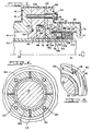
- Figure 1 is a side sectional view of the pump and dynamic seal arrangement of the present invention.
- Figure 2 is a side sectional view on an enlarged seal of the dynamic seal arrangement of Figure 1.
- Figure 3 is a side sectional view of an alternate embodiment of the dynamic seal arrangement of the present invention.
- Figure 4 is a cross-sectional view of the dynamic seal arrangement shown in Figure 2 taken along lines 4-4.
- Figure 5 is a cross-sectional view of the dynamic seal arrangement shown in Figure 2 taken along lines 5-5.
- A known impeller pump, generally designated by the
numeral 10, is shown in Figure 1. Thepump 10 includes ahousing 12 having acircular wall 14 and defining aninterior bore 16 and anannular flange 18. Ashaft 20 is rotatably mounted in thehousing bore 16 and has asleeve 22 disposed thereabout and keyed thereto so that thesleeve 22 rotates with theshaft 20. - A
main impeller 24 is disposed within animpeller cavity region 26 and is keyed to rotate with theshaft 20. Liquid to be pumped enters theimpeller 24 at acentral inlet region 28.Radial vanes 30 extending from thefront face 32 of theimpeller 24 centrifugally dispel the fluid radially outwardly to anoutlet region 34.Radial vanes 36 also extend from therear face 38 of theimpeller 24 which is spaced from an adjacentradial wall 40 of thehousing 12. Theradial wall 40 defines anannular cavity region 42 which is in fluid communication with theimpeller cavity 26 and in fluid communication with thehousing bore 16 via an expellerimpeller cavity region 44. - An expeller, generally designated by the
numeral 46 is disposed within the expellerimpeller cavity region 44 of thehousing 12 and is keyed to rotate with theshaft 20. Theexpeller 46 defines anexpeller impeller 48 whose smoothfront face 50 is disposed radially of theannular cavity 42 and spaced from, but adjacent, theradial housing wall 40. Therear face 52 of theexpeller impeller 48 is provided withradial vanes 54 extending therefrom, thevanes 54 spaced from, but proximately adjacent thehousing wall 56. - Fluid leakage can occur between the
main impeller 10 and theradial housing wall 40 via theannular cavity region 42 to the shaft bore 16. Theexpeller 46 is provided to counteract this fluid movement, at least when thepump 10 is operating, to pump fluid from theannular cavity 42 to thepump outlet 34. When theshaft 20, the main impeller vanes 30 and 36, and theexpeller impeller vanes 54 all are rotating, the outward centrifugal action of the pumped liquid is away from theannular cavity region 42 and the shaft bore 16 and directed toward theoutlet region 34 of thepump 10. This minimizes or even totally eliminates fluid leakage from the pump housing alongshaft 16. No seal mechanism to prevent leakage alongshaft 20 is needed when the pump is operating. However, when theshaft 20 ceases to rotate, the shaft bore 16 and theannular cavity region 42 become flooded and fluid leakage can occur directly between thehousing 12 and theshaft 20. - As seen in Figures 1 and 2, an
annular gland plate 60 is disposed adjacent theannular flange 18 of thepump housing 12. Aseal housing 62, defining an annularseal cavity region 64 through which theshaft 20 extends, is provided. Theseal housing 64 defines an outwardly dependingflange 66 at one end thereof.Bolts 68 are inserted through theflange 66 of theseal housing 62, thegland plate 60, and theflange 66 of thepump housing 12, thereby connecting them in secure relation. The end of theseal housing 62 opposite theflange 66 provides aradial wall 70 defining anopening 72 at the lower periphery thereof which vents theseal cavity region 64 to atmosphere. A rubberizedprotective coating 74 covers the outer surfaces of both thepump housing 12 and theseal housing 62. This coating is indicative of pumps used in corrosive environments. - The dynamic face seal of the present invention, designated generally by the
numeral 58, includes an annular rotatingprimary seal ring 76 having a radially extendingface 78 and an annular stationary or non-rotatingmating seal ring 80 having a radially extendingface 82. Theradial faces rings shaft sleeve 22 andshaft 20 such that thesurfaces - The
primary seal ring 76 includes aface portion 76a and an axially expandedbody portion 76b and is axially movable and held in place by anannular retainer 88 disposed in theseal cavity region 64, as best seen in Figures 2 and 3. Theradial face 78 of theprimary seal ring 76 is smooth and flat across its entire surface. Asnap ring 90 is received in anannular groove 92 in theretainer 88 and holds thebody portion 76b of theprimary seal ring 76 within theretainer 88. Theretainer 88 defines a plurality ofbores 94 equally spaced about the circumference of theretainer 88, as best seen in Figure 4. Springs 96 are seated in thebores 94 and act against anannular disc 98 to urge theprimary seal ring 76 into engagement with themating seal ring 80 and provide for axial movement of theprimary seal ring 76.Retainer 88 may have one or moreinternal grooves 150 and thebody portion 76b of theprimary seal ring 76 an equal number of aligned grooves.Drive pins 151 are disposed to engage both theretainer 88 and primary sealring body portion 76b to provide driving engagement without interference with axial movement. A generallycylindrical retainer sleeve 100 is disposed about theshaft sleeve 22 such that it is positioned between theshaft 20 and theretainer 88 andprimary seal ring 76. An O-ring 102 is received in anannular groove 104 defined about the outer periphery of thesleeve 100 to provide a seal between theprimary seal ring 76 and thesleeve 100. Another O-ring 106 is received in anannular groove 108 defined about the inner periphery of thesleeve 100 to provide a seal between theshaft sleeve 22 and theretainer sleeve 100. Setscrews 110, as best seen in Figure 4, extend through theretainer 88,retainer sleeve 100 andshaft sleeve 22 to secure them to theshaft 20 so that they, and, consequently, theprimary seal ring 76, rotate with theshaft 20. Theshaft 20 rotates in a clockwise direction when viewing thepump 10 from the right, as indicated in Figures 2 and 3. - The
mating seal ring 80 is fixed with respect to theflange 18 of thehousing 12 and thegland plate 60 so that it is precluded from rotating with theshaft 20. Agasket 112 provides a seal between thehousing 12 and themating seal ring 80. As best seen in Figure 5, theradial face 82 of themating seal ring 80 defines a plurality ofspiral grooves 114 which extend inwardly from the outer periphery thereof to adam 116 defined at the inner periphery thereof. The width of thegrooves 114 converge as they near thedam 116. Aland 118 separates eachgroove 114. In the illustrated embodiment, the outer circumferential peripheries ofrings ring 80 exposed to low pressure and extend toward, but short of, the circumferential periphery exposed to the pressure in the pump such that the grooves extend from the outside diameter of the circle defined by the boundary between the grooved area and the smooth area of theface 82 to the circumferential periphery exposed to ambient pressure and thedam 116 extends from the internal diameter of the circle to the circumferential periphery exposed to low pressure. - Figure 3 shows an alternate embodiment for mounting the
mating seal ring 80. A gland plate 120 is keyed to theflange 18 of thehousing 12 and an O-ring 122 received in anannular groove 124 defined in the gland plate 120 seals against leakage between thehousing flange 18 and the gland plate 120. The gland plate 120 defines anannular recess 126 in which themating seal ring 80 is disposed. An O-ring 128 provides a seal between the gland plate 120 and themating seal ring 80. Asecond gland plate 130 is keyed to the gland plate 120 so that themating seal ring 80 is retained between the gland plate 120 and thesecond gland plate 130.Bolts 134 secure thesecond gland plate 130, the gland plate 120 and thehousing flange 18. - During operation of the
impeller pump 10, theexpeller 46 evacuates liquid from theannular cavity region 44 and the shaft boreregion 16 eliminating the need for a seal along theshaft 20. the seal faces 78, 82 are therefore adapted to be separated during pump operation.Shaft 20 andprimary seal ring 76 rotate, causing pumping action between the faces because of thespiral grooves 114 defined on the radial seal face 82 of themating seal ring 80. This causes low pressure or ambient fluid external to the pump to enter between thefaces face 78 of theprimary seal ring 76 to lift away from theface 82 of themating seal ring 80 against the biasing effect of thesprings 96 in theretainer 88 so that theprimary seal ring 76 is moved axially with respect to theshaft 20 andretainer 88. This reduces the drag, eliminates wear of the seal faces 78, 82 and prevents undue heat generation. - However, when the
pump 10 is not operating, liquid may leak into theannular cavity region 44, the shaft boreregion 16 and the annularseal cavity region 64. Therefore, it is desirable to seal off these regions. When theshaft 20 stops rotating, theprimary seal ring 76 no longer pumps air into thespiral grooves 114 of themating seal ring 80. Thesprings 96 in the primaryseal ring retainer 88 axially urge theradial face 78 of theprimary seal ring 76 into engagement with theradial face 82 of themating seal ring 80, particularly thedam 116 thereof, thereby providing a static seal against fluid leakage. - The
primary seal ring 76 may be made of carbon and themating seal ring 80 may be made of silicon carbide. The O-rings gasket 112 may be formed of Chemlon. The other structural components, as theshaft 20, theshaft sleeve 22, thepump housing 12, theseal housing 62, thegland plates retainer 88, thesprings 114, thesnap ring 90 and thedisc 98, may be made of stainless steel. - While the above described embodiment discloses a
primary seal ring 76 having a smoothradial face 78 and amating seal ring 80 having aradial face 82 definingspiral grooves 114 thereacross, it will be understood that theradial face 78 of theprimary seal ring 76 may define spiral grooves and theradial face 82 of themating seal ring 80 may be smooth. - The disclosed
seal arrangement 58 of the present invention may have particular utility in containing acid slurries, lime slurries, caustic cleaning solutions, sandy water, sludge or even corn syrup. - Thus, it has been shown that the present invention provides a dynamic seal for an impeller pump to seal against the leakage of liquid when the pump is not operating.
- Various features of this invention have been particularly shown and described in connection with the illustrated embodiment of the invention. However, it must be understood that these particular arrangements merely illustrate and that the invention is to be given its fullest interpretation within the terms of the appended claims.
Claims (10)
- Pump (10) including a rotatable shaft (20), an impeller (24) on the shaft (20) to pressurize fluid during rotation of shaft (20), a pump housing (12) defining a cavity region (16) surrounding the shaft (20), means sealing the shaft (20) and the pump housing (12) against fluid leakage therebetween during pumping operation and when the shaft (20) is not rotating, the means comprising in combination:
expeller means to maintain the fluid being pumped away from the cavity region (16) during pumping operation, thereby eliminating the need for a fluid tight seal between the pump housing (12) and the shaft (20) during pumping operation,
and a dynamic seal arrangment (58) for providing a seal between the pump housing (12) and the shaft (20), the dynamic seal arrangement (58) comprising:
an axially movable primary seal ring (76) adapted to be disposed annularly about the shaft (20) and secured in fluid tight relation to either the shaft (20) or the pump housing (12), the primary seal ring (76) defining a radial seal face (78);
a stationary mating seal ring (80) adapted to be disposed annularly about the shaft (20) and secured in fluid tight relation to either the pump housing (12) or the shaft (20), the mating seal ring (80) defining a radial seal face (82) adapted for sealing contact with the radial seal face (78) of the primary seal ring (76);
wherein one (78) of the radial seal faces (78,82) of one seal ring (76,80) defines a smooth surface and the radial seal face (82) of the other seal ring defines a surface having a plurality of spiral grooves (114) therein, the radial seal faces (78,82) being exposed to the fluid within the pump (10) at one circumferential periphery and to the atmosphere external to the pump at the opposite circumferential periphery, the grooves (114) extending from the circumferential periphery exposed to atmosphere external to the pump radially partially toward the other circumferential periphery thereof and terminating to define on the radial seal face (80), between the spiral grooves (114) and the circumferential periphery exposed to the fluid within the pump (10), a sealing dam (116) adapted to sealingly engage the smooth radial seal face (78) of one of the seal rings (76,80);
biasing means urging the axially movable primary ring (76) towards the stationary mating seal ring (80) to cause the sealing dam (116) to engage the radial seal face (78) of the other ring (76) when the shaft (20) is not rotating;
the spiral grooves (114) pumping atmosphere between the radial seal faces (78,82) when the shaft (20) is rotating at operational speed at a pressure to separate the radial seal faces (78,82) of the seal rings (76,80). - Pump according to claim 1, characterised by an expeller (46) provided on the shaft (20) in a cavity region (42) of the pump housing (12) between the impeller (24) and the dynamic seal arrangement (58), the expeller (46) being rotatable with the shaft (20) to evacuate fluid from a cavity region (16) and the dynamic seal arrangment (58) during pumping operation, thereby eliminating the need for a fluid tight seal between the pump housing (12) and the shaft (20) during the pumping operation.
- Pump as in claims 1 and 2, characterised in that the width of the spiral grooves (114) converge as they extend from the one circumferential periphery towards the other circumferential periphery.
- Pump as in claim 1 or 2, characterised in that the stationary mating ring (80) is secured in fluid tight relation with the pump housing (12).
- Pump as in claim 1 or 2, characterised in that the axially movable primary ring (76) is secured in fluid tight relation with the shaft (20).
- Pump as in at least one of claims 1 to 3, characterised in that the spiral grooves (114) extend from the outside diameter of a circle defined by a boundary between the grooved area and the smooth area of the radial seal face (82) to the circumferential periphery, and that the sealing dam (116) extends from the internal diameter of the circle to the other circumferential periphery.
- Pump as in claim 1 or 2, characterised by an annular seal housing (62) disposed about the shaft (20) and defining a seal housing cavity (64) within which the dynamic seal arrangement (58) is disposed, the seal housing (62) being connectable to the pump housing (12).
- Pump as in claim 7, characterised in that the seal housing (62) defines a radial wall (70) defining an annular opening (72) about the shaft (20) to vent the seal housing cavity to atmosphere.
- Pump as in claim 1 or 2, characterised by a retaining element (88) associated with the primary seal ring (76) and retaining the primary seal ring (76) therein, the retaining element (88) being disposed annularly about and rotable with the shaft (20) and defining a plurality of bores (94), each bore (94) having seated therein a spring (96) biasing the primary seal ring (76) into engagement with the mating seal ring (80) to provide a static seal.
- Method for sealing a shaft (20) relative to a pump housing (12) in a pump (10) against fluid leakage therebetween during pumping operation and when the shaft (20) is not rotating, the pump (10) including the rotatable shaft (20) and impeller (24) on the shaft (20) to pressurize fluid during rotation of the shaft (20) with operational speed, the pump housing (12) defining a cavity region (16) surrounding the shaft (20), and a dynamic seal arrangment (58) to seal between the pump housing (12) and the shaft (20), the dynamic seal arrangment (58) comprising:
an axially movable primary seal ring (76) defining a radial seal face (78);
a stationary mating seal ring (80) defining a radial seal face (82) adapted for sealing contact with the radial seal face (78);
wherein one radial seal face (78) defines a smooth surface and the other radial seal face (82) defines a surface having a plurality of spiral grooves (114) as well as a sealing dam (116) adapted to sealingly engage the smooth radial surface of the one seal face (78), the radial seal faces (78,82) being exposed to the fluid within the pump (10) at one circumferential periphery and to the atmosphere external to the pump (10) at the opposite circumferential periphery, and
biasing means urging the primary seal ring (76) towards the stationary mating seal ring (80),
comprising the following steps:
during operation of the pump with rotation of the shaft at operational speed, leakage of the fluid to be pumped within the pump between the shaft and the pump housing is prevented by maintaining the fluid away from the dynamic seal arrangement and evacuating the fluid away from the rotating shaft and creating a back pressure sufficient to overcome the contained fluid pressure by expeller means provided on the shaft between the main impeller and the dynamic seal arrangement, and by simultaneously pumping atmosphere from the exterior between the radial seal faces of the dynamic seal arrangment, and
with the shaft not rotating at operational speed preventing leakage of the fluid between the shaft and the pump housing by axial biased engagement between the smooth sealing dam and the smooth radial surface of the other radial seal face.
Applications Claiming Priority (3)
| Application Number | Priority Date | Filing Date | Title |
|---|---|---|---|
| US222196 | 1981-01-02 | ||
| US07/222,196 US4884945A (en) | 1988-07-21 | 1988-07-21 | Dynamic seal arrangement for impeller pump |
| PCT/US1989/003130 WO1990001118A1 (en) | 1988-07-21 | 1989-07-17 | Dynamic seal arrangement for impeller pump |
Publications (3)
| Publication Number | Publication Date |
|---|---|
| EP0425576A1 EP0425576A1 (en) | 1991-05-08 |
| EP0425576A4 EP0425576A4 (en) | 1992-05-06 |
| EP0425576B1 true EP0425576B1 (en) | 1995-03-15 |
Family
ID=22831274
Family Applications (1)
| Application Number | Title | Priority Date | Filing Date |
|---|---|---|---|
| EP89908956A Expired - Lifetime EP0425576B1 (en) | 1988-07-21 | 1989-07-17 | Dynamic seal arrangement for impeller pump |
Country Status (8)
| Country | Link |
|---|---|
| US (1) | US4884945A (en) |
| EP (1) | EP0425576B1 (en) |
| JP (1) | JPH04500993A (en) |
| KR (1) | KR0125009B1 (en) |
| BR (1) | BR8907572A (en) |
| CA (1) | CA1307422C (en) |
| DE (1) | DE68921755T2 (en) |
| WO (1) | WO1990001118A1 (en) |
Families Citing this family (29)
| Publication number | Priority date | Publication date | Assignee | Title |
|---|---|---|---|---|
| US5195755A (en) * | 1989-12-25 | 1993-03-23 | Eagle Industry Co., Ltd. | Shaft seal for slurry pumps |
| US5224714A (en) * | 1990-07-18 | 1993-07-06 | Ebara Corporation | Noncontacting face seal |
| US5133639A (en) * | 1991-03-19 | 1992-07-28 | Sta-Rite Industries, Inc. | Bearing arrangement for centrifugal pump |
| US5375853B1 (en) * | 1992-09-18 | 1998-05-05 | Crane John Inc | Gas lubricated barrier seal |
| US5344163A (en) * | 1992-09-28 | 1994-09-06 | Goulds Pumps, Incorporated | Dynamic shaft seal for pumping fibrous slurries |
| TW265395B (en) * | 1993-03-18 | 1995-12-11 | Warman Int Ltd | |
| US5447078A (en) * | 1993-09-17 | 1995-09-05 | Reliance Electric Industrial Company | Submersible gearmotor |
| US5941532A (en) * | 1996-06-20 | 1999-08-24 | Rexnord Corporation | Aerospace housing and shaft assembly with noncontacting seal |
| US5938206A (en) * | 1996-11-01 | 1999-08-17 | John Crane Inc. | Pressure responsive primary ring for a non-contacting mechanical end face seal |
| US5934683A (en) * | 1997-07-10 | 1999-08-10 | Roy E. Roth Company | Rotary seal assembly having grooved seal facing |
| US6109617A (en) * | 1998-03-04 | 2000-08-29 | Power Packing Co., Inc. | Gas seal assembly and method of sealing |
| US6074166A (en) * | 1998-10-01 | 2000-06-13 | Moddemeijer; Pieter J. H. | Pump |
| US6299173B1 (en) | 1998-10-16 | 2001-10-09 | John Crane Inc. | Mechanical end face seal ring having a compliant seal face |
| FR2824365A1 (en) * | 2001-05-04 | 2002-11-08 | Stein Seal Compagny | Sealing system for coolant pump used in nuclear power plant, has back-up sealing arrangement shaped to close its seal gap, when pump shaft is not rotating |
| US7036523B2 (en) * | 2001-06-22 | 2006-05-02 | Kenneth Nixon | Serviceable check valve |
| SE525029C2 (en) * | 2001-07-13 | 2004-11-16 | Abs Pump Prod Ab | Device at centrifugal pump |
| US6629816B2 (en) | 2001-08-16 | 2003-10-07 | Honeywell International Inc. | Non-contacting clearance seal for high misalignment applications |
| GB0317055D0 (en) * | 2003-07-22 | 2003-08-27 | Cross Mfg Co 1938 Ltd | Improvements relating to aspirating face seals and thrust bearings |
| US20080003099A1 (en) * | 2006-06-30 | 2008-01-03 | Honeywell International, Inc. | Closed bias air film riding seal in event of housing breach for shared engine lubrication accessory gearboxes |
| DE102009005386A1 (en) * | 2009-01-21 | 2010-07-22 | Bosch Mahle Turbo Systems Gmbh & Co. Kg | Charging device for an internal combustion engine |
| GB0908201D0 (en) * | 2009-05-13 | 2009-06-24 | Crane John Uk Ltd | Seal assemblies |
| DE102009023907A1 (en) * | 2009-06-04 | 2010-12-09 | Ksb Aktiengesellschaft | Sealing system for centrifugal pumps |
| US8657573B2 (en) * | 2010-04-13 | 2014-02-25 | Rolls-Royce Corporation | Circumferential sealing arrangement |
| DE102012012443A1 (en) * | 2012-06-22 | 2013-12-24 | Wilo Se | Motor centrifugal pump with a mechanical seal |
| JP2014025411A (en) * | 2012-07-26 | 2014-02-06 | Furukawa Industrial Machinery Systems Co Ltd | Shaft sealing device of centrifugal pump |
| DE102012214276A1 (en) * | 2012-08-10 | 2014-02-13 | Siemens Aktiengesellschaft | A shaft seal assembly |
| DE102013007165B4 (en) * | 2013-04-24 | 2015-05-21 | Eagleburgmann Germany Gmbh & Co. Kg | Mechanical seal assembly of simplified construction |
| US8888105B1 (en) | 2013-05-29 | 2014-11-18 | Stephen J. Andrews | Mechanical seal system |
| CN106015080B (en) * | 2016-07-25 | 2018-06-26 | 浙江工业大学 | Wear-resisting type sealing device for submersible sewage pump |
Family Cites Families (6)
| Publication number | Priority date | Publication date | Assignee | Title |
|---|---|---|---|---|
| US2258527A (en) * | 1939-01-10 | 1941-10-07 | Warman Charles Harold | Centrifugal pump |
| US3068801A (en) * | 1958-09-02 | 1962-12-18 | Murray William | Centrifugal impeller pumps |
| FR1456862A (en) * | 1965-09-14 | 1966-07-08 | Soc Et Propulsion Par Reaction | Sealing device for rotating shaft |
| US4212475A (en) * | 1979-01-15 | 1980-07-15 | Crane Packing Co. | Self aligning spiral groove face seal |
| US4290611A (en) * | 1980-03-31 | 1981-09-22 | Crane Packing Co. | High pressure upstream pumping seal combination |
| DE3722110A1 (en) * | 1987-07-03 | 1989-01-12 | Burgmann Dichtungswerk Feodor | THE ARRANGEMENT OF A GAS LUBRICATED MECHANICAL SEAL AND SEAL ARRANGEMENT FOR A SHAFT |
-
1988
- 1988-07-21 US US07/222,196 patent/US4884945A/en not_active Ceased
-
1989
- 1989-07-17 WO PCT/US1989/003130 patent/WO1990001118A1/en not_active Ceased
- 1989-07-17 DE DE68921755T patent/DE68921755T2/en not_active Expired - Fee Related
- 1989-07-17 JP JP1508425A patent/JPH04500993A/en active Pending
- 1989-07-17 EP EP89908956A patent/EP0425576B1/en not_active Expired - Lifetime
- 1989-07-17 BR BR898907572A patent/BR8907572A/en not_active IP Right Cessation
- 1989-07-17 KR KR1019900700593A patent/KR0125009B1/en not_active Expired - Fee Related
- 1989-07-18 CA CA000606042A patent/CA1307422C/en not_active Expired - Lifetime
Also Published As
| Publication number | Publication date |
|---|---|
| JPH04500993A (en) | 1992-02-20 |
| AU628372B2 (en) | 1992-09-17 |
| KR0125009B1 (en) | 1997-12-23 |
| KR900702238A (en) | 1990-12-06 |
| BR8907572A (en) | 1991-06-18 |
| CA1307422C (en) | 1992-09-15 |
| DE68921755D1 (en) | 1995-04-20 |
| EP0425576A4 (en) | 1992-05-06 |
| AU4039689A (en) | 1990-02-19 |
| US4884945A (en) | 1989-12-05 |
| WO1990001118A1 (en) | 1990-02-08 |
| EP0425576A1 (en) | 1991-05-08 |
| DE68921755T2 (en) | 1995-07-20 |
Similar Documents
| Publication | Publication Date | Title |
|---|---|---|
| US4884945A (en) | Dynamic seal arrangement for impeller pump | |
| US5553867A (en) | Triple cartridge seal having one inboard and two concentric seals for chemical processing pump | |
| US5498007A (en) | Double gas barrier seal | |
| US4288083A (en) | Hydrodynamic shaft seal | |
| EP0037210B1 (en) | High pressure upstream pumping seal combination | |
| EP0446531B1 (en) | Mechanical seal | |
| AU667384B2 (en) | Gas lubricated barrier seal | |
| EP2055962B1 (en) | Centrifugal pump, a shaft sleeve and a stationary seal member | |
| GB2216964A (en) | Rotating shaft seal | |
| GB2213541A (en) | Pump impeller seals | |
| US3515497A (en) | Centrifugal pump having hydraulic seal means | |
| US3652180A (en) | Centrifugal pump and seal means therefore | |
| US3731940A (en) | Elastomer seal with a plurality of annular ribs for a rotating shaft of a centrifugal pump or the like | |
| US4948336A (en) | Mechanical shaft seal | |
| MX2008008722A (en) | Flexible floating ring seal arrangement for rotodynamic pumps. | |
| USRE34319E (en) | Dynamic seal arrangement for impeller pump | |
| US4722149A (en) | Anti-shuttle pump | |
| US4606712A (en) | Self-pumping pump shaft seal | |
| US2781209A (en) | Dynamic seal for a centrifugal pump | |
| AU628372C (en) | Dynamic seal arrangement for impeller pump | |
| US5368313A (en) | Bushing for trapped bushing seal | |
| EP4048901B1 (en) | A pump arrangement for pumping barrier liquid and a mechanical shaft seal | |
| JP2801722B2 (en) | Pump device | |
| CA2021935A1 (en) | Seals | |
| US20250003427A1 (en) | Oil-lubricated vacuum pump with improved oil sealing |
Legal Events
| Date | Code | Title | Description |
|---|---|---|---|
| PUAI | Public reference made under article 153(3) epc to a published international application that has entered the european phase |
Free format text: ORIGINAL CODE: 0009012 |
|
| 17P | Request for examination filed |
Effective date: 19910118 |
|
| AK | Designated contracting states |
Kind code of ref document: A1 Designated state(s): BE DE FR GB IT NL SE |
|
| A4 | Supplementary search report drawn up and despatched |
Effective date: 19920319 |
|
| AK | Designated contracting states |
Kind code of ref document: A4 Designated state(s): BE DE FR GB IT NL SE |
|
| 17Q | First examination report despatched |
Effective date: 19930722 |
|
| GRAA | (expected) grant |
Free format text: ORIGINAL CODE: 0009210 |
|
| AK | Designated contracting states |
Kind code of ref document: B1 Designated state(s): BE DE FR GB IT NL SE |
|
| ET | Fr: translation filed | ||
| REF | Corresponds to: |
Ref document number: 68921755 Country of ref document: DE Date of ref document: 19950420 |
|
| ITF | It: translation for a ep patent filed | ||
| PG25 | Lapsed in a contracting state [announced via postgrant information from national office to epo] |
Ref country code: GB Effective date: 19950717 |
|
| PG25 | Lapsed in a contracting state [announced via postgrant information from national office to epo] |
Ref country code: BE Effective date: 19950731 |
|
| PLBE | No opposition filed within time limit |
Free format text: ORIGINAL CODE: 0009261 |
|
| STAA | Information on the status of an ep patent application or granted ep patent |
Free format text: STATUS: NO OPPOSITION FILED WITHIN TIME LIMIT |
|
| BERE | Be: lapsed |
Owner name: JOHN CRANE INC. Effective date: 19950731 |
|
| PG25 | Lapsed in a contracting state [announced via postgrant information from national office to epo] |
Ref country code: NL Effective date: 19960201 |
|
| 26N | No opposition filed | ||
| GBPC | Gb: european patent ceased through non-payment of renewal fee |
Effective date: 19950717 |
|
| NLV4 | Nl: lapsed or anulled due to non-payment of the annual fee |
Effective date: 19960201 |
|
| PG25 | Lapsed in a contracting state [announced via postgrant information from national office to epo] |
Ref country code: FR Effective date: 19960430 |
|
| REG | Reference to a national code |
Ref country code: FR Ref legal event code: ST |
|
| REG | Reference to a national code |
Ref country code: FR Ref legal event code: ST |
|
| REG | Reference to a national code |
Ref country code: FR Ref legal event code: ST |
|
| PGFP | Annual fee paid to national office [announced via postgrant information from national office to epo] |
Ref country code: SE Payment date: 20020723 Year of fee payment: 14 |
|
| PGFP | Annual fee paid to national office [announced via postgrant information from national office to epo] |
Ref country code: DE Payment date: 20020828 Year of fee payment: 14 |
|
| PG25 | Lapsed in a contracting state [announced via postgrant information from national office to epo] |
Ref country code: SE Free format text: LAPSE BECAUSE OF NON-PAYMENT OF DUE FEES Effective date: 20030718 |
|
| PG25 | Lapsed in a contracting state [announced via postgrant information from national office to epo] |
Ref country code: DE Free format text: LAPSE BECAUSE OF NON-PAYMENT OF DUE FEES Effective date: 20040203 |
|
| EUG | Se: european patent has lapsed | ||
| PG25 | Lapsed in a contracting state [announced via postgrant information from national office to epo] |
Ref country code: IT Free format text: LAPSE BECAUSE OF NON-PAYMENT OF DUE FEES;WARNING: LAPSES OF ITALIAN PATENTS WITH EFFECTIVE DATE BEFORE 2007 MAY HAVE OCCURRED AT ANY TIME BEFORE 2007. THE CORRECT EFFECTIVE DATE MAY BE DIFFERENT FROM THE ONE RECORDED. Effective date: 20050717 |
|
| P01 | Opt-out of the competence of the unified patent court (upc) registered |
Effective date: 20230522 |