EP0425099B1 - Stabilised fabrics - Google Patents
Stabilised fabrics Download PDFInfo
- Publication number
- EP0425099B1 EP0425099B1 EP90310530A EP90310530A EP0425099B1 EP 0425099 B1 EP0425099 B1 EP 0425099B1 EP 90310530 A EP90310530 A EP 90310530A EP 90310530 A EP90310530 A EP 90310530A EP 0425099 B1 EP0425099 B1 EP 0425099B1
- Authority
- EP
- European Patent Office
- Prior art keywords
- fabric
- mesh
- stabilising means
- hose
- threads
- Prior art date
- Legal status (The legal status is an assumption and is not a legal conclusion. Google has not performed a legal analysis and makes no representation as to the accuracy of the status listed.)
- Expired - Lifetime
Links
Images

Classifications
-
- B—PERFORMING OPERATIONS; TRANSPORTING
- B29—WORKING OF PLASTICS; WORKING OF SUBSTANCES IN A PLASTIC STATE IN GENERAL
- B29C—SHAPING OR JOINING OF PLASTICS; SHAPING OF MATERIAL IN A PLASTIC STATE, NOT OTHERWISE PROVIDED FOR; AFTER-TREATMENT OF THE SHAPED PRODUCTS, e.g. REPAIRING
- B29C70/00—Shaping composites, i.e. plastics material comprising reinforcements, fillers or preformed parts, e.g. inserts
- B29C70/04—Shaping composites, i.e. plastics material comprising reinforcements, fillers or preformed parts, e.g. inserts comprising reinforcements only, e.g. self-reinforcing plastics
- B29C70/06—Fibrous reinforcements only
- B29C70/10—Fibrous reinforcements only characterised by the structure of fibrous reinforcements, e.g. hollow fibres
- B29C70/16—Fibrous reinforcements only characterised by the structure of fibrous reinforcements, e.g. hollow fibres using fibres of substantial or continuous length
- B29C70/22—Fibrous reinforcements only characterised by the structure of fibrous reinforcements, e.g. hollow fibres using fibres of substantial or continuous length oriented in at least two directions forming a two-dimensional [2D] structure
-
- B—PERFORMING OPERATIONS; TRANSPORTING
- B29—WORKING OF PLASTICS; WORKING OF SUBSTANCES IN A PLASTIC STATE IN GENERAL
- B29C—SHAPING OR JOINING OF PLASTICS; SHAPING OF MATERIAL IN A PLASTIC STATE, NOT OTHERWISE PROVIDED FOR; AFTER-TREATMENT OF THE SHAPED PRODUCTS, e.g. REPAIRING
- B29C48/00—Extrusion moulding, i.e. expressing the moulding material through a die or nozzle which imparts the desired form; Apparatus therefor
- B29C48/001—Combinations of extrusion moulding with other shaping operations
- B29C48/0018—Combinations of extrusion moulding with other shaping operations combined with shaping by orienting, stretching or shrinking, e.g. film blowing
-
- B—PERFORMING OPERATIONS; TRANSPORTING
- B29—WORKING OF PLASTICS; WORKING OF SUBSTANCES IN A PLASTIC STATE IN GENERAL
- B29C—SHAPING OR JOINING OF PLASTICS; SHAPING OF MATERIAL IN A PLASTIC STATE, NOT OTHERWISE PROVIDED FOR; AFTER-TREATMENT OF THE SHAPED PRODUCTS, e.g. REPAIRING
- B29C48/00—Extrusion moulding, i.e. expressing the moulding material through a die or nozzle which imparts the desired form; Apparatus therefor
- B29C48/03—Extrusion moulding, i.e. expressing the moulding material through a die or nozzle which imparts the desired form; Apparatus therefor characterised by the shape of the extruded material at extrusion
- B29C48/09—Articles with cross-sections having partially or fully enclosed cavities, e.g. pipes or channels
-
- B—PERFORMING OPERATIONS; TRANSPORTING
- B29—WORKING OF PLASTICS; WORKING OF SUBSTANCES IN A PLASTIC STATE IN GENERAL
- B29C—SHAPING OR JOINING OF PLASTICS; SHAPING OF MATERIAL IN A PLASTIC STATE, NOT OTHERWISE PROVIDED FOR; AFTER-TREATMENT OF THE SHAPED PRODUCTS, e.g. REPAIRING
- B29C48/00—Extrusion moulding, i.e. expressing the moulding material through a die or nozzle which imparts the desired form; Apparatus therefor
- B29C48/15—Extrusion moulding, i.e. expressing the moulding material through a die or nozzle which imparts the desired form; Apparatus therefor incorporating preformed parts or layers, e.g. extrusion moulding around inserts
- B29C48/154—Coating solid articles, i.e. non-hollow articles
-
- B—PERFORMING OPERATIONS; TRANSPORTING
- B29—WORKING OF PLASTICS; WORKING OF SUBSTANCES IN A PLASTIC STATE IN GENERAL
- B29C—SHAPING OR JOINING OF PLASTICS; SHAPING OF MATERIAL IN A PLASTIC STATE, NOT OTHERWISE PROVIDED FOR; AFTER-TREATMENT OF THE SHAPED PRODUCTS, e.g. REPAIRING
- B29C48/00—Extrusion moulding, i.e. expressing the moulding material through a die or nozzle which imparts the desired form; Apparatus therefor
- B29C48/25—Component parts, details or accessories; Auxiliary operations
- B29C48/285—Feeding the extrusion material to the extruder
- B29C48/288—Feeding the extrusion material to the extruder in solid form, e.g. powder or granules
- B29C48/2883—Feeding the extrusion material to the extruder in solid form, e.g. powder or granules of preformed parts, e.g. inserts, retaining their shape during the extrusion process
-
- D—TEXTILES; PAPER
- D03—WEAVING
- D03D—WOVEN FABRICS; METHODS OF WEAVING; LOOMS
- D03D13/00—Woven fabrics characterised by the special disposition of the warp or weft threads, e.g. with curved weft threads, with discontinuous warp threads, with diagonal warp or weft
- D03D13/002—With diagonal warps or wefts
-
- D—TEXTILES; PAPER
- D03—WEAVING
- D03D—WOVEN FABRICS; METHODS OF WEAVING; LOOMS
- D03D15/00—Woven fabrics characterised by the material, structure or properties of the fibres, filaments, yarns, threads or other warp or weft elements used
- D03D15/50—Woven fabrics characterised by the material, structure or properties of the fibres, filaments, yarns, threads or other warp or weft elements used characterised by the properties of the yarns or threads
- D03D15/56—Woven fabrics characterised by the material, structure or properties of the fibres, filaments, yarns, threads or other warp or weft elements used characterised by the properties of the yarns or threads elastic
-
- D—TEXTILES; PAPER
- D03—WEAVING
- D03D—WOVEN FABRICS; METHODS OF WEAVING; LOOMS
- D03D9/00—Open-work fabrics
-
- D—TEXTILES; PAPER
- D04—BRAIDING; LACE-MAKING; KNITTING; TRIMMINGS; NON-WOVEN FABRICS
- D04B—KNITTING
- D04B21/00—Warp knitting processes for the production of fabrics or articles not dependent on the use of particular machines; Fabrics or articles defined by such processes
- D04B21/10—Open-work fabrics
- D04B21/12—Open-work fabrics characterised by thread material
-
- D—TEXTILES; PAPER
- D10—INDEXING SCHEME ASSOCIATED WITH SUBLASSES OF SECTION D, RELATING TO TEXTILES
- D10B—INDEXING SCHEME ASSOCIATED WITH SUBLASSES OF SECTION D, RELATING TO TEXTILES
- D10B2505/00—Industrial
- D10B2505/02—Reinforcing materials; Prepregs
Definitions
- This invention relates to the use of textile fabrics as a reinforcement of products including radiator hoses.
- Reinforced hoses and other reinforced products, and also reinforcing fabrics, are often exposed to high temperatures during production and/or shaping, and in service. It is also usual for the fabric to be slit, heat-treated and/or to have a textile/matrix adhesive system applied.
- a reinforcing fabric may be intimately bonded to a, say, curable rubber or plastics matrix. Under these conditions at least, the fabric should be dimensionallystable, and should not distort or change its shape when tensioned.
- EP-A-0100573 describes a method for shaping a hose of material including a reinforcing fabric, and curing the material in the desired shape.
- the fabric will not stretch as much as might be desired and will therefore tear, whereupon the wall of the hose may also tear/burst at the outside of the bend. If the reinforcing fabric does not tear, the inner side of the bend will fold: the internal cross-section of the tube is therefore distorted.
- a conventional reinforcing fabric can be stretched in the longitudinal direction sufficiently to allow bending of the hose, the likely result is that the fabric will stretch during production of a hose, resulting in a change in fabric orientation.
- the fabric's tensile strength or width may thus be changed undesirably, e.g. by reducing or removing the overlap between the edges of a fabric defining an annulus in a green hose, thus affecting the properties of the product when shaped. In other words, the fabric will not have the desired degree of dimensional stability.
- a particular object behind the present invention is to provide a fabric which can withstand the forces applied to it when incorporated as a reinforcement in a composite product, and be stretched to a limited extent only during this procedure, but which should also allow the product to be bent into a desired shape, while retaining its reinforcing function.
- GB-A-2117418 discloses a fabric woven from warp ends, weft threads, and oppositely-inclined diagonal threads.
- the fabric is tubular and may be embedded in a synthetic resin.
- a method for producing a shaped product comprises the steps of:
- a reinforced product is produced from a fabric which is dimensionally-stable, and the product is then treated or otherwise handled to destroy the stabilising means in situ, and give the advantage of easy shaping.
- An important advantage of the present invention is that, on the one hand, distortion of the fabric during slitting and incorporation into a matrix is avoided, and, on the other hand, shaping of a product reinforced by the fabric is possible without deformation, e.g. buckling or tearing.
- Suitable base fabrics may be of conventional mesh type. They may be non-woven, as obtained by laying filaments from two directions, e.g. having a Stabilon or Chavanoz-type construction. Preferred mesh fabrics are woven or, most preferably, knitted. They may also be produced with a biased warp and weft, by spirally slitting a tubular fabric woven on a circular loom, or woven double on a flat loom. Examples of suitable materials are aramids, cotton, rayon, polyester, polyamide, PVA, PVDF and any other known filamentary system.
- the mesh fabric is one which has a degree of stretchability in one or both dimensions.
- the base fabric is stabilised by the insertion, into the fabric construction, of a longitudinal carrier thread.
- the carrier thread may be a low strength filamentary material of sufficient strength to carry the fabric through slitting and the production of, say, a green hose, without distortion.
- the stabilised fabric is incorporated into a composite product that requires shaping, e.g. a radiator coolant hose, the carrier thread is capable of breaking or passing its yield point, if appropriate on heating, thus enabling the shaping action to take place.
- the carrier thread may consist of a thermoplastic material having an initial high modulus and high extension beyond its yield point. This material may or may not melt during subsequent processing, e.g. rubber cure. Thermoplasticity of the material can be utilised, in producing the stabilising fabric, to fix the mesh angle of the fabric at a desired value.
- a suitable thermoplastic material melts at at least 125°C, at least 150°C or at least 165°C. Polypropylene, polyethylene or low-melting nylon is preferred.
- the carrier thread may be bonded to the mesh fabric in any desired manner, e.g. adhesively and/or by stitching. Stitching may be particularly appropriate for an inlay mesh fabric.
- the base fabric has applied thereto a system that "locks" the fabric. Again, this may serve to provide a desired mesh angle.
- a system that "locks" the fabric may serve to provide a desired mesh angle.
- Examples of application methods are dot-coating, powder-coating and other applications of a binding composition.
- a binding composition is, for example, a latex, a resorcinol formaldehyde/latex composition, a PVC plastisol or any other adhesive system.
- the binding is adapted to be releasable under given conditions.
- Binding or any other stabilising means may be released at a given temperature or under other conditions.
- release may be chemically-activated, e.g. by including a material which gives an agent affecting the stabilising means under certain conditions.
- a material may be included in the fabric or in the matrix reinforced by the fabric.
- the method of the invention may be conducted by generally known techniques, i.e. the separate extrusion of two layers of extrudable matrix material and the insertion therebetween of the reinforcing fabric.
- the product is preferably in the form of a tube or hose, but it will be apparent that the invention is equally applicable to the production of other products, such as cables, upholstery, boots or other footwear, roofing or tent reinforcement, and bicycle tyres.
- the invention is appropriate for use in cases where the product has to be bent through an arc or otherwise deformed into a desired shape. Shaping may be sufficient to provide a stable product: if necessary, curing or vulcanisation may follow.
- a hose may be produced by extruding material from first and second coaxial extrusion heads, and continuously supplying a strip of stabilised reinforcing fabric between the heads.
- the strip is applied so that its longitudinal edges are contiguous or overlapping, the strip being applied onto the inner layer of extruded material.
- the reinforcing fabric should preferably have a sufficiently open structure that the material or materials extruded through the coaxial heads can flow together through the fabric.
- the stabilised reinforcing fabric has a modulus of elasticity which is relatively high, and thus a low degree of stretch, e.g. under tension up to a certain value. When the tension exceeds this value, the stabilising means may break or deconstruct, or the modulus of elasticity may be relatively low, and the fabric can therefore be relatively easily stretched. Initially, the fabric will maintain its shape when a force is applied in the longitudinal direction of the hose. When the hose is bent, the fabric is under strain at the outside of the bend, such that the stabilising means will be destroyed or deconstructed, or become yielding, so that the fabric can be stretched together with the material of the hose. Neither the base fabric nor the wall of the hose tears. The cross-section and stability of the hose are maintained.
- the fabric essentially comprises only, or substantially only, the mesh.
- the relative melting points of the mesh fabric and stabilising means are not critical. However, if the stabilising means is not breakable or yielding, the melting point of the stabilising means should be lower than that of the mesh fabric.
- the reinforcing fabric can be in the shape of a knitted or woven fabric with an open structure and with meshes in the shape of a rhombus, parallelogram or other rectangle; opposing corner points of succeeding meshes lie on a line which, when the fabric is laid in the hose material, extends substantially parallel to the longitudinal direction of the hose, and are connected by longitudinal threads. These threads effect their connecting function as long as this is necessary, especially during slitting the fabric and a green hose production process.
- the reinforcing fabric may comprise a woven fabric whose warp and weft threads are at a given distance from each other and are connected to each other at opposing corner points by means of connecting threads that extend at an oblique angle over the woven fabric.
- the connection itself can be achieved by, for example, welding or adhesively-binding the warp and weft threads and the connecting threads to each other. Welding is particularly suitable if the threads are of thermoplastic material. In this case, the warp threads will not coincide with the longitudinal direction of the hose to which the fabric is applied. This is less preferred, owing to the subsequent loss of material.
- the reinforcing fabric is formed by a knitted fabric, in particular a knitted fabric produced by means of a Raschel machine.
- the meshes may thus be defined by double threads. In this case, the corner points of the meshes can simply be connected to stabilising threads, without welding or glueing.
- aramid material is less suitable to be looped, and a base fabric of such a material may comprise a bonded mesh of linear filaments. If desired, stabilising carrier threads may be stitched in.
- the meshes are defined by sides making an angle of 40° to 80°, e.g. 40° to 70°, preferably 45° to 65°, e.g. about 54°, with the longitudinal direction of the fabric and of a hose or other product including the fabric.
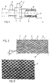
- Fig. 1 of the accompanying drawings shows an extrusion device 1 comprising coaxial extrusion heads 2 and 3 with respective connections 4 and 5 for the supply of material to be extruded.
- the extrusion heads 2 and 3 respectively provide an inner hose portion 6 and an outer hose portion 7.
- a reinforcing fabric 8 is supplied onto the hose portion 6 via a slit positioned between the extrusion heads 2,3.
- hose portions 6 and 7 and the reinforcing fabric 8 are shown at some distance from each other. It will be readily appreciated that the hose portions 6 and 7 are in fact closely attached to each other, to form a hose 9.
- Fig. 2 shows one example of a reinforcing fabric, e.g. the fabric 8, comprising threads 10 and 11 defining rhomboid meshes 12.
- the threads 10,11 each define an angle ⁇ with respect to both the longitudinal direction L of the reinforcing fabric and also the longitudinal direction of the hose 9.
- the angle ⁇ is, for example, 54°.
- the threads 14 are of limited tensile strength, but can withstand the force which is exerted on the fabric 8 in the direction L during extrusion of the hose portions 6 and 7, during which the fabric is stretched only to a limited extent.
- the stretch to which the threads 14 is subjected, in particular in the outer portion of the bend, is sufficient to exceed the yielding or breaking point of the threads 14.
- Figs. 3 and 4 use, for the purposes of analogy only, the same reference numerals as in Fig. 2. They illustrate a reinforcing fabric of the invention, e.g. the reinforcing fabric 8, obtained by means of a Raschel machine.
- the threads 10,11 comprise knitted stitches and are double-threaded.
- the connecting threads 14 may also be double-threaded, and may be knitted with the threads 10,11 at the points 13, to provide the reinforcing fabric with good dimensional stability.
- the connecting threads 14 may be welded or glued to the other threads at the points 13.
- Fig. 5 shows a woven fabric, e.g. the fabric 8, comprising elastic warp threads 15 and also warp threads 16 having a substantially higher stiffness.
- the threads 16 break or yield when a given force is exerted in the direction of the arrow K.
- Fig. 6 shows the elasticity of a reinforcing fabric, with respect to an increasing applied force K.
- K b At a given force K b and a degree of stretch r b , stabilising threads (14 or 16) yield or break. Thereafter, only a small force K 1 has to be exerted on the fabric to maintain the stretch r b , and the stretch can increase considerably as K is increased only to a small extent. Under these conditions, the modulus of elasticity of the fabric is small, so that the fabric can be stretched easily and brought into the desired shape, without losing the fabric's ability to reinforce the product.
- Fig. 7 corresponds in part to Fig. 6.
- stabilising threads 14 or 16
- the stretchability of the reinforcing fabric increases considerably, for only a small increase in applied force.
- a dimensionally-unstable (in the sense that it can be stretched in the warp and weft directions) fabric is based on 420 dtex aramid (Twaron) and an Atlas stitch of 3.35 whales/cm and 9.9 columns/cm.
- the total greige weight is about 80 g/m 2 .
- This fabric is stabilised by the introduction of a 78 dtex polypropylene yarn as carrier thread, to give a fabric as illustrated in Figs. 3 and 4.
- this fabric is passed through a dipping unit where an adhesive coating of an RFL is applied and dried at a temperature just under the melting point, so that the carrier yarn shrinks to form a high modulus carrier. It is also possible to heat-set the fabric, without applying any coating.
- the stabilised fabric is used for the reinforcement of a coolant hose by means of apparatus as illustrated in Fig. 1.
- the carrier thread ensures that the diamond pattern of the reinforcement is not distorted during slitting and extrusion.
- the carrier thread extends beyond its yield or break. If the temperature during shaping is above 165°C, the polypropylene carrier thread will meld.
- a dimensionally-unstable fabric of the same type of construction and also commonly used as a reinforcement for automotive coolant hose is based on 1220 dtex rayon and has an Atlas stitch of 4.72 whales/cm and 5.51 columns/cm. The total greige weight is about 163 g/m 2 .
- the mesh fabric is stabilised by the introduction of a 78 dtex polypropylene yarn. After knitting, this fabric is taken through a stenter. RFL adhesive treatment of the fabric at this stage is optional. By the influence of the heat, the carrier yarn is shrunk to form a high modulus carrier yarn. At the same time the fabric is brought under the desired reinforcement angle (40° to 70°) according to the application needs.
- the carrier yarn ensures that the fabric does not lose its shape during the following processes, e.g. slitting and extrusion. During shaping, a higher load will be applied which will extend the carrier yarn or break it.
Landscapes
- Engineering & Computer Science (AREA)
- Textile Engineering (AREA)
- Mechanical Engineering (AREA)
- Chemical & Material Sciences (AREA)
- Composite Materials (AREA)
- Woven Fabrics (AREA)
- Laminated Bodies (AREA)
- Treatments For Attaching Organic Compounds To Fibrous Goods (AREA)
- Knitting Of Fabric (AREA)
- Rigid Pipes And Flexible Pipes (AREA)
- Extrusion Moulding Of Plastics Or The Like (AREA)
- Powder Metallurgy (AREA)
- Chemical Or Physical Treatment Of Fibers (AREA)
- Treatment Of Fiber Materials (AREA)
Abstract
Description
Claims (13)
- A method for producing a shaped product, which comprises the steps of:(a) extruding layers (6,7) of an extrudable material; and(b) applying therebetween a mesh fabric (8,10,11) additionally comprising stabilising means (14) that provide the mesh fabric with substantially no elasticity in at least one direction; characterised by(c) shaping the fabric-reinforced product under conditions which cause breakage, deconstruction or yielding of the stabilising means but which do not affect the mesh fabric.
- A method according to claim 1, in which the mesh fabric is woven or knitted.
- A method according to claim 1 or claim 2, in which the filaments (10,11) defining the mesh are at an angle (α) of 40° to 70° with respect to the longitudinal direction of the fabric.
- A method according to any preceding claim, in which the stabilising means is a thermoplastic material.
- A method according to any preceding claim, in which the stabilising means comprises polypropylene.
- A method according to any preceding claim, in which the stabilising means comprises a binder.
- A method according to any preceding claim, in which the stabilising means comprises parallel threads which are capable of breaking or yielding under tension without affecting the mesh fabric.
- A method according to claim 7, in which the parallel threads extend between the opposing corners (13) of the mesh.
- A method according to any preceding claim, in which the extrudable material comprises a rubber or plastics matrix.
- A method according to any preceding claim, in which the shaped product is at least partially arcuate, and in which the shaping reduces or removes the effect of the stabilising means at the outside of the arc.
- A method according to claim 10, in which the fabric is as defined in claim 7 or claim 8, the parallel threads extending in the direction of the arc.
- A method according to claim 10 or claim 11, in which the shaped product is a hose (9).
- A method according to any preceding claim, in which the layers of extrudable material are extruded through coaxial extrusion heads (2,3).
Applications Claiming Priority (6)
| Application Number | Priority Date | Filing Date | Title |
|---|---|---|---|
| GB898921938A GB8921938D0 (en) | 1989-09-28 | 1989-09-28 | Stabilised fabrics |
| GB8921938 | 1989-09-28 | ||
| NL8902868A NL8902868A (en) | 1989-11-21 | 1989-11-21 | Mesh fabric reinforcing hose - includes stabilising threads running between crossing-points of intersecting threads |
| NL8902868 | 1989-11-21 | ||
| NL8902869 | 1989-11-21 | ||
| NL8902869A NL8902869A (en) | 1989-11-21 | 1989-11-21 | Mesh fabric reinforcing hose - includes stabilising threads running between crossing-points of intersecting threads |
Publications (3)
| Publication Number | Publication Date |
|---|---|
| EP0425099A2 EP0425099A2 (en) | 1991-05-02 |
| EP0425099A3 EP0425099A3 (en) | 1992-03-04 |
| EP0425099B1 true EP0425099B1 (en) | 1998-08-26 |
Family
ID=27264708
Family Applications (1)
| Application Number | Title | Priority Date | Filing Date |
|---|---|---|---|
| EP90310530A Expired - Lifetime EP0425099B1 (en) | 1989-09-28 | 1990-09-26 | Stabilised fabrics |
Country Status (13)
| Country | Link |
|---|---|
| US (1) | US5229056A (en) |
| EP (1) | EP0425099B1 (en) |
| JP (1) | JP2898386B2 (en) |
| KR (1) | KR0139081B1 (en) |
| AT (1) | ATE170238T1 (en) |
| AU (1) | AU640689B2 (en) |
| CA (1) | CA2026413C (en) |
| DE (1) | DE69032592T2 (en) |
| ES (1) | ES2119742T3 (en) |
| FI (1) | FI106805B (en) |
| IE (1) | IE80898B1 (en) |
| NO (1) | NO180111C (en) |
| PT (1) | PT95458B (en) |
Families Citing this family (28)
| Publication number | Priority date | Publication date | Assignee | Title |
|---|---|---|---|---|
| CA2087576C (en) * | 1993-01-19 | 2003-08-05 | Robert L. Richardson | Weeping hose |
| GB9309951D0 (en) * | 1993-05-14 | 1993-06-30 | Milliken Europ Nv | Stabilised fabrics and reinforced products containing them |
| US5698282A (en) * | 1993-09-02 | 1997-12-16 | Milliken Research Corporation | Stabilized fabrics and reinforced products containing them |
| US5653923A (en) * | 1996-02-29 | 1997-08-05 | Owens-Corning Fiberglas Technology, Inc. | Method for making shaped members using a foam froth |
| US5948505A (en) | 1997-03-28 | 1999-09-07 | Andersen Corporation | Thermoplastic resin and fiberglass fabric composite and method |
| DE19803656C2 (en) * | 1998-01-30 | 2000-02-17 | Milliken Europ Nv | Band-shaped textile product and method for producing a body reinforced with the textile product |
| US7267141B1 (en) | 2000-06-05 | 2007-09-11 | Milliken & Company | Method of on-site production of novel textile reinforced thermoplastic or thermoset pipes |
| US6455115B1 (en) | 2001-01-26 | 2002-09-24 | Milliken & Company | Textile reinforced thermoplastic or thermoset pipes |
| US6627281B2 (en) | 2001-01-26 | 2003-09-30 | Milliken & Company | Textile reinforced thin-walled thermoplastic or thermoset medium pressure pipes |
| US6663808B2 (en) * | 2001-01-26 | 2003-12-16 | Milliken & Company | Method of producing textile reinforced thermoplastic or thermoset pipes utilizing modified dorn structures |
| US6305423B1 (en) | 2000-06-05 | 2001-10-23 | Milliken & Company | Thermoplastic or thermoset pipes including conductive textile reinforcements for heating and leak detection purposes |
| DE10036235C2 (en) * | 2000-07-26 | 2002-10-31 | Geiger Technik Gmbh | Media line made of rubber-like plastic, especially cooling water hose |
| EP1304404A1 (en) * | 2001-10-17 | 2003-04-23 | Milliken Europe N.V. | Reinforcement fabrics having at least two reinforcement directions |
| US7163652B1 (en) * | 2002-12-20 | 2007-01-16 | Hunter Douglas | Process for producing co-extruded profiles |
| US8503577B2 (en) | 2003-07-17 | 2013-08-06 | Agere Systems Llc | Signal quality estimation in a wireless communication system |
| US7459205B2 (en) | 2003-09-05 | 2008-12-02 | Flexmaster Co. Ltd. | Reinforcing net |
| ES2243133B1 (en) * | 2004-05-12 | 2006-07-01 | Relats, S.A. | PROCEDURE FOR THE MANUFACTURE OF PROTECTION PIPES. |
| FR2892664B1 (en) * | 2005-10-27 | 2007-12-07 | Michelin Soc Tech | PNEUMATIC COMPRISING A BIELASTIC REINFORCING ELEMENT |
| FR2901177B1 (en) * | 2006-05-22 | 2008-07-25 | Michelin Soc Tech | PNEUMATIC WITH LOW AREA COMPRISING A BIELASTIC REINFORCING ELEMENT |
| US7572745B2 (en) * | 2006-09-26 | 2009-08-11 | The Gates Corporation | Fluid transfer hose reinforced with hybrid yarn |
| DE102007050041A1 (en) * | 2007-10-17 | 2009-04-23 | Gustav Ernstmeier Gmbh & Co Kg | Web-shaped material |
| US20150202837A1 (en) * | 2012-08-15 | 2015-07-23 | Frederick James Coetzee | Reinforced rubberised transport systems |
| GB201215043D0 (en) * | 2012-08-23 | 2012-10-10 | Scott & Fyfe Ltd | Reinforcing fabric |
| JP6453843B2 (en) | 2013-03-13 | 2019-01-16 | フェデラル−モーグル・パワートレイン・リミテッド・ライアビリティ・カンパニーFederal−Mogul Powertrain Llc | Wrapping sleeve with warp knitting with extendable electrical function yarn and method of construction |
| DE102014103861B4 (en) | 2014-03-20 | 2016-12-22 | Müller Textil GmbH | Spacer knit and method for producing a spacer knitted fabric |
| CN104712856A (en) | 2014-12-09 | 2015-06-17 | 南通倍佳机械科技有限公司 | Two-layer composite hose and manufacturing method thereof |
| KR20170140311A (en) * | 2015-05-08 | 2017-12-20 | 미르카 리미티드 | Abrasive belt grinding products |
| WO2020242513A1 (en) * | 2019-05-30 | 2020-12-03 | Delta Plastics Of The South (Arkansas Corporation) | Woven irrigation tubing, apparatus and method of making same |
Family Cites Families (17)
| Publication number | Priority date | Publication date | Assignee | Title |
|---|---|---|---|---|
| US3310447A (en) * | 1962-08-30 | 1967-03-21 | Moore & Co Samuel | Composite tubing method of manufacture |
| GB1210182A (en) * | 1968-07-29 | 1970-10-28 | Angus George Co Ltd | Improvements in the manufacture of flexible hose pipes |
| US3653233A (en) * | 1968-12-05 | 1972-04-04 | Titone Research & Dev Corp | Machine knitting |
| BE786513A (en) * | 1971-07-21 | 1972-11-16 | Pirelli | METHOD OF MANUFACTURING CONNECTION SLEEVES FOR RADIATORS OF MOTOR VEHICLES AND SLEEVES THUS OBTAINED |
| DE2314172A1 (en) * | 1973-03-22 | 1974-10-03 | Messerschmitt Boelkow Blohm | Three layer fibre reinforcement - fibres laid without weaving then bonded |
| US3866205A (en) * | 1973-04-18 | 1975-02-11 | Louis B Payne | Locking device with alarm utilizing flexible gas impermeable tube |
| FR2328565A1 (en) * | 1975-10-08 | 1977-05-20 | Schmidt Karl | PROCESS AND INSTALLATION FOR THE MANUFACTURING OF RUBBER PIPES OF CURVED SHAPE |
| US4155790A (en) * | 1977-01-12 | 1979-05-22 | H. K. Porter Company, Inc. | Continuous manufacture of reinforced hose |
| US4385018A (en) * | 1977-11-21 | 1983-05-24 | Automation Industries, Inc. | Method and apparatus for making insulated, reinforced flexible hose |
| FR2492418A1 (en) * | 1980-10-20 | 1982-04-23 | Lastex Files | THERMOCOLATING ELASTIC WIRE |
| GB2117418A (en) * | 1982-03-19 | 1983-10-12 | Hinaya Kk | Fabric and tubular article using said fabric |
| NL8203075A (en) * | 1982-08-02 | 1984-03-01 | Vredestein Nv | METHOD FOR MANUFACTURING A HOSE FROM A FORM-FIXED ELASTOMER MATERIAL, SUCH AS A VULLCANIZED RUBBER, IN PARTICULAR A HOSE FOR THE COOLING MEDIUM OF A CAR. |
| DE3508864A1 (en) * | 1985-03-13 | 1986-10-16 | Müller, Karl Heinz | TEXTILE RAILWAY MATERIAL FROM FABRIC OR KNIT |
| JPS62112572A (en) * | 1985-11-11 | 1987-05-23 | 帝人株式会社 | Webbing for seat belt |
| FR2595621B1 (en) * | 1986-03-12 | 1988-11-04 | Europ Propulsion | METHOD FOR MANUFACTURING A REINFORCING STRUCTURE FOR A PART MADE OF COMPOSITE MATERIAL |
| US4741873A (en) * | 1986-04-15 | 1988-05-03 | Kaiser Aerotech, A Division Of Sowa & Sons | Method for forming rigid composite preforms |
| US4738735A (en) * | 1986-11-05 | 1988-04-19 | Mercedes Textiles Limited | Method and apparatus for continuously extruding an elastomeric material on the interior of a continuous tubular woven fabric in a loom |
-
1990
- 1990-09-24 IE IE343490A patent/IE80898B1/en not_active IP Right Cessation
- 1990-09-25 AU AU63182/90A patent/AU640689B2/en not_active Ceased
- 1990-09-26 EP EP90310530A patent/EP0425099B1/en not_active Expired - Lifetime
- 1990-09-26 ES ES90310530T patent/ES2119742T3/en not_active Expired - Lifetime
- 1990-09-26 AT AT90310530T patent/ATE170238T1/en not_active IP Right Cessation
- 1990-09-26 DE DE69032592T patent/DE69032592T2/en not_active Expired - Fee Related
- 1990-09-27 KR KR1019900015371A patent/KR0139081B1/en not_active Expired - Fee Related
- 1990-09-27 FI FI904763A patent/FI106805B/en not_active IP Right Cessation
- 1990-09-27 NO NO904216A patent/NO180111C/en not_active IP Right Cessation
- 1990-09-27 CA CA002026413A patent/CA2026413C/en not_active Expired - Fee Related
- 1990-09-28 JP JP2257572A patent/JP2898386B2/en not_active Expired - Lifetime
- 1990-09-28 PT PT95458A patent/PT95458B/en active IP Right Grant
-
1991
- 1991-10-16 US US07/775,394 patent/US5229056A/en not_active Expired - Lifetime
Also Published As
| Publication number | Publication date |
|---|---|
| IE80898B1 (en) | 1999-06-02 |
| KR0139081B1 (en) | 1998-05-15 |
| EP0425099A2 (en) | 1991-05-02 |
| JPH03241036A (en) | 1991-10-28 |
| EP0425099A3 (en) | 1992-03-04 |
| NO904216L (en) | 1991-04-02 |
| AU6318290A (en) | 1991-04-11 |
| PT95458A (en) | 1991-05-22 |
| CA2026413A1 (en) | 1991-03-29 |
| ES2119742T3 (en) | 1998-10-16 |
| FI904763A0 (en) | 1990-09-27 |
| CA2026413C (en) | 2001-02-27 |
| ATE170238T1 (en) | 1998-09-15 |
| PT95458B (en) | 1997-11-28 |
| NO180111B (en) | 1996-11-11 |
| KR910006540A (en) | 1991-04-29 |
| DE69032592D1 (en) | 1998-10-01 |
| DE69032592T2 (en) | 1999-05-12 |
| NO904216D0 (en) | 1990-09-27 |
| IE903434A1 (en) | 1991-04-10 |
| NO180111C (en) | 1997-02-19 |
| FI106805B (en) | 2001-04-12 |
| US5229056A (en) | 1993-07-20 |
| AU640689B2 (en) | 1993-09-02 |
| JP2898386B2 (en) | 1999-05-31 |
Similar Documents
| Publication | Publication Date | Title |
|---|---|---|
| US5229056A (en) | Producing fabric reinforced hose | |
| US5416961A (en) | Knitted wire carrier having bonded warp threads and method for forming same | |
| EP2953800B1 (en) | Pneumatic tire carcass having air blocking stabilizing fabric system | |
| EP0725723B1 (en) | Stabilised fabrics and reinforced products containing them | |
| JP3971470B2 (en) | Reinforced fabric ply and composite | |
| US5698282A (en) | Stabilized fabrics and reinforced products containing them | |
| EP1015679B1 (en) | Wire carrier with reduced elongation | |
| JPH03213790A (en) | Hose and manufacture thereof | |
| JPH02243407A (en) | Wire carrier and its producing method | |
| JPS6022503A (en) | Pneumatic tire | |
| KR20030020866A (en) | Hose and pipe reinforcement | |
| JPH10315708A (en) | Blind fabric for tire reinforcement and pneumatic tire using the same | |
| GB2199629A (en) | Kink resistant hose | |
| JPS6163761A (en) | Rubber reinforcing material | |
| JP2001526371A (en) | Fabric reinforced layered members for hoses, tubes and similar elongated bodies and articles made therefrom |
Legal Events
| Date | Code | Title | Description |
|---|---|---|---|
| PUAI | Public reference made under article 153(3) epc to a published international application that has entered the european phase |
Free format text: ORIGINAL CODE: 0009012 |
|
| AK | Designated contracting states |
Kind code of ref document: A2 Designated state(s): AT BE CH DE DK ES FR GB GR IT LI LU NL SE |
|
| PUAL | Search report despatched |
Free format text: ORIGINAL CODE: 0009013 |
|
| AK | Designated contracting states |
Kind code of ref document: A3 Designated state(s): AT BE CH DE DK ES FR GB GR IT LI LU NL SE |
|
| 17P | Request for examination filed |
Effective date: 19920820 |
|
| 17Q | First examination report despatched |
Effective date: 19940610 |
|
| GRAG | Despatch of communication of intention to grant |
Free format text: ORIGINAL CODE: EPIDOS AGRA |
|
| GRAG | Despatch of communication of intention to grant |
Free format text: ORIGINAL CODE: EPIDOS AGRA |
|
| GRAG | Despatch of communication of intention to grant |
Free format text: ORIGINAL CODE: EPIDOS AGRA |
|
| GRAH | Despatch of communication of intention to grant a patent |
Free format text: ORIGINAL CODE: EPIDOS IGRA |
|
| GRAH | Despatch of communication of intention to grant a patent |
Free format text: ORIGINAL CODE: EPIDOS IGRA |
|
| GRAA | (expected) grant |
Free format text: ORIGINAL CODE: 0009210 |
|
| AK | Designated contracting states |
Kind code of ref document: B1 Designated state(s): AT BE CH DE DK ES FR GB GR IT LI LU NL SE |
|
| PG25 | Lapsed in a contracting state [announced via postgrant information from national office to epo] |
Ref country code: CH Free format text: LAPSE BECAUSE OF FAILURE TO SUBMIT A TRANSLATION OF THE DESCRIPTION OR TO PAY THE FEE WITHIN THE PRESCRIBED TIME-LIMIT Effective date: 19980826 Ref country code: LI Free format text: LAPSE BECAUSE OF FAILURE TO SUBMIT A TRANSLATION OF THE DESCRIPTION OR TO PAY THE FEE WITHIN THE PRESCRIBED TIME-LIMIT Effective date: 19980826 Ref country code: GR Free format text: LAPSE BECAUSE OF FAILURE TO SUBMIT A TRANSLATION OF THE DESCRIPTION OR TO PAY THE FEE WITHIN THE PRESCRIBED TIME-LIMIT Effective date: 19980826 Ref country code: AT Free format text: LAPSE BECAUSE OF FAILURE TO SUBMIT A TRANSLATION OF THE DESCRIPTION OR TO PAY THE FEE WITHIN THE PRESCRIBED TIME-LIMIT Effective date: 19980826 |
|
| REF | Corresponds to: |
Ref document number: 170238 Country of ref document: AT Date of ref document: 19980915 Kind code of ref document: T |
|
| REG | Reference to a national code |
Ref country code: CH Ref legal event code: EP |
|
| ITF | It: translation for a ep patent filed | ||
| REF | Corresponds to: |
Ref document number: 69032592 Country of ref document: DE Date of ref document: 19981001 |
|
| REG | Reference to a national code |
Ref country code: ES Ref legal event code: FG2A Ref document number: 2119742 Country of ref document: ES Kind code of ref document: T3 |
|
| ET | Fr: translation filed | ||
| PG25 | Lapsed in a contracting state [announced via postgrant information from national office to epo] |
Ref country code: SE Free format text: LAPSE BECAUSE OF FAILURE TO SUBMIT A TRANSLATION OF THE DESCRIPTION OR TO PAY THE FEE WITHIN THE PRESCRIBED TIME-LIMIT Effective date: 19981126 Ref country code: DK Free format text: LAPSE BECAUSE OF FAILURE TO SUBMIT A TRANSLATION OF THE DESCRIPTION OR TO PAY THE FEE WITHIN THE PRESCRIBED TIME-LIMIT Effective date: 19981126 |
|
| REG | Reference to a national code |
Ref country code: CH Ref legal event code: PL |
|
| PLBE | No opposition filed within time limit |
Free format text: ORIGINAL CODE: 0009261 |
|
| STAA | Information on the status of an ep patent application or granted ep patent |
Free format text: STATUS: NO OPPOSITION FILED WITHIN TIME LIMIT |
|
| 26N | No opposition filed | ||
| PGFP | Annual fee paid to national office [announced via postgrant information from national office to epo] |
Ref country code: LU Payment date: 20000925 Year of fee payment: 11 |
|
| PGFP | Annual fee paid to national office [announced via postgrant information from national office to epo] |
Ref country code: ES Payment date: 20010920 Year of fee payment: 12 |
|
| PG25 | Lapsed in a contracting state [announced via postgrant information from national office to epo] |
Ref country code: LU Free format text: LAPSE BECAUSE OF NON-PAYMENT OF DUE FEES Effective date: 20010926 |
|
| PGFP | Annual fee paid to national office [announced via postgrant information from national office to epo] |
Ref country code: NL Payment date: 20010927 Year of fee payment: 12 |
|
| REG | Reference to a national code |
Ref country code: GB Ref legal event code: IF02 |
|
| PG25 | Lapsed in a contracting state [announced via postgrant information from national office to epo] |
Ref country code: ES Free format text: LAPSE BECAUSE OF NON-PAYMENT OF DUE FEES Effective date: 20020927 |
|
| PG25 | Lapsed in a contracting state [announced via postgrant information from national office to epo] |
Ref country code: NL Free format text: LAPSE BECAUSE OF NON-PAYMENT OF DUE FEES Effective date: 20030401 |
|
| REG | Reference to a national code |
Ref country code: ES Ref legal event code: FD2A Effective date: 20031011 |
|
| PGFP | Annual fee paid to national office [announced via postgrant information from national office to epo] |
Ref country code: GB Payment date: 20070926 Year of fee payment: 18 |
|
| PGFP | Annual fee paid to national office [announced via postgrant information from national office to epo] |
Ref country code: IT Payment date: 20070927 Year of fee payment: 18 Ref country code: DE Payment date: 20071031 Year of fee payment: 18 |
|
| PGFP | Annual fee paid to national office [announced via postgrant information from national office to epo] |
Ref country code: BE Payment date: 20071025 Year of fee payment: 18 |
|
| PGFP | Annual fee paid to national office [announced via postgrant information from national office to epo] |
Ref country code: FR Payment date: 20070917 Year of fee payment: 18 |
|
| BERE | Be: lapsed |
Owner name: *VREDESTEIN ICORPO B.V. Effective date: 20080930 Owner name: *MILLIKEN EUROPE N.V. Effective date: 20080930 |
|
| GBPC | Gb: european patent ceased through non-payment of renewal fee |
Effective date: 20080926 |
|
| REG | Reference to a national code |
Ref country code: FR Ref legal event code: ST Effective date: 20090529 |
|
| PG25 | Lapsed in a contracting state [announced via postgrant information from national office to epo] |
Ref country code: BE Free format text: LAPSE BECAUSE OF NON-PAYMENT OF DUE FEES Effective date: 20080930 |
|
| PG25 | Lapsed in a contracting state [announced via postgrant information from national office to epo] |
Ref country code: DE Free format text: LAPSE BECAUSE OF NON-PAYMENT OF DUE FEES Effective date: 20090401 Ref country code: IT Free format text: LAPSE BECAUSE OF NON-PAYMENT OF DUE FEES Effective date: 20080926 |
|
| PG25 | Lapsed in a contracting state [announced via postgrant information from national office to epo] |
Ref country code: FR Free format text: LAPSE BECAUSE OF NON-PAYMENT OF DUE FEES Effective date: 20080930 |
|
| PG25 | Lapsed in a contracting state [announced via postgrant information from national office to epo] |
Ref country code: GB Free format text: LAPSE BECAUSE OF NON-PAYMENT OF DUE FEES Effective date: 20080926 |