EP0425036B1 - Method of matching a variable two-dimensional image of a known three-dimensional object with a desired two-dimensional image of the object - Google Patents
Method of matching a variable two-dimensional image of a known three-dimensional object with a desired two-dimensional image of the object Download PDFInfo
- Publication number
- EP0425036B1 EP0425036B1 EP90202802A EP90202802A EP0425036B1 EP 0425036 B1 EP0425036 B1 EP 0425036B1 EP 90202802 A EP90202802 A EP 90202802A EP 90202802 A EP90202802 A EP 90202802A EP 0425036 B1 EP0425036 B1 EP 0425036B1
- Authority
- EP
- European Patent Office
- Prior art keywords
- image
- variable
- images
- variable image
- dimensional
- Prior art date
- Legal status (The legal status is an assumption and is not a legal conclusion. Google has not performed a legal analysis and makes no representation as to the accuracy of the status listed.)
- Expired - Lifetime
Links
Images


Classifications
-
- G—PHYSICS
- G06—COMPUTING OR CALCULATING; COUNTING
- G06V—IMAGE OR VIDEO RECOGNITION OR UNDERSTANDING
- G06V10/00—Arrangements for image or video recognition or understanding
- G06V10/70—Arrangements for image or video recognition or understanding using pattern recognition or machine learning
- G06V10/74—Image or video pattern matching; Proximity measures in feature spaces
- G06V10/75—Organisation of the matching processes, e.g. simultaneous or sequential comparisons of image or video features; Coarse-fine approaches, e.g. multi-scale approaches; using context analysis; Selection of dictionaries
- G06V10/751—Comparing pixel values or logical combinations thereof, or feature values having positional relevance, e.g. template matching
- G06V10/7515—Shifting the patterns to accommodate for positional errors
Definitions
- the invention relates to a method of matching a variable two-dimensional image of a known three-dimensional object with a desired two-dimensional image of that object by step-wise changing the variable image in the case of non-correspondence between the images.
- a set of edges and corners representing a contour is used to match an image with different kinds of models.
- This method is used for determining spatial relationships between an object and a camera which is movable by means of a robot.
- small two-dimensional templates are matched with the actual image in order to extract positions of edges and corners. Subsequently, an investigation is started as to which object location could have produced this combination of corner and edges locations.
- Corners and edges appear and disappear when the orientation of the object changes.
- an object having a complex set of enclosed corners and edges such as an industrial tool used for assembly
- the search process must check an enormous amount of possibilities.
- the projection may introduce fictitious corners.
- the image of object parts situated at different distances from the camera may ensue fictitious corners.
- the invention is characterized in that global features in the images and/or global features of the modulo-2 subtraction of the images are used to calculate a scalar global parameter as a measure of conformance between the two images, and therefrom to determine a desired step-wise change of the variable image as being governed by motion in three dimensions in order to obtain a new variable image, until a final step brings about a sufficiently conforming match.
- the three-dimensional approach solves many situations, whilst the scalar parameter as a deviation indicating quantity allows a quick decision.
- US Patent 4,658,428 discloses a method for frame or template generation wherein a plurality of templates of an object, depicting it in various orientations, can be generated from a single input image.
- the present invention relates to matching of a variable image with a desired image of the object.
- the difference between the present invention and this reference is best grasped from reading the reference's Claim 1, wherein exclusively translation and rotation of the object within the template frame are attained by detecting the centroid position of the image, and also a best-fitting ellipse therearound. Essentially, this is therefore a two-dimensional method.
- the present invention not only position and orientation, but also the shape of the variable image are influenced in developing the matching.
- the method in accordance with the invention strongly deviates from the known method.
- For input use is made of global image features such as surfaces and centres of gravity. Because these features are only vaguely related to specific object parts, the object cannot be recognised in the sense that it is known how parts of the image relate to parts of a model.
- the output is formed by desirable changes of, for example, the positions of the camera with respect to the object.
- new images can be obtained as follows, depending on the intended application: using a camera which is moved by a robot in the case of robot positioning or using simulation by means of a computer program capable of producing a perspective view of a configuration of an object, observed as if it were via a camera, on the basis of the geometrical description of the object, together with its positions and orientations, the camera position and orientation and a description of the camera optical system in the case of camera location calibration or object location measurement where physical movements are not allowed.
- the grip of the robot comprises a camera, or more generally an image sensor
- the grip can be instructed to move to a location specified with respect to a given object. This task is useful when an object is approached so as to be gripped.
- camera location calibration measurement of the relation between camera and object can be used to calibrate the camera location if the location of an object and its geometry are known.
- object location measurement the position and rotation of a known object can be measured as from a known camera location.
- the method in accordance with the invention starts with a spatial initial relation and step-wise calculates changes in order to optimise the matching of a variable image with a desirable image or reference image of the object in the desired location. It is assumed that the specified relative location has been reached when the variable image matches the desirable image.
- the desirable image is the image of the object which is observed from the specified relative location.
- the variable image or projected image originates from the movable camera.
- the desirable image is the image observed by the camera, the variable image being produced by said computer program which is capable of changing the virtual camera location or the virtual object location.
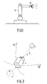
- a robot 10 as shown in Fig. 1 comprises a grip 20 with an image sensor 2, such as a camera, which is mounted in the grip 20.
- an image sensor 2 such as a camera
- a purely scalar minimisation algorithm can be used if the correspondence between two images can be expressed as a single number.
- a modulo-2 image subtraction produces the areas where the images differ.
- the total surface area of this subtraction can be used as input for the minimisation algorithm.
- the problem is thus reduced to the finding of a minimum in a six-dimensional environment of the difference in pixels for the six parameters.
- simplex algorithm which is known from the publication by Marco S. Caceci et al "Fitting Curves to Data", Byte, May 1984, pages 340-362.
- a simplex is defined as the simplest geometric structure containing an N-dimensional volume.
- An N-dimensional simplex can be described by N+1 points, each point representing a specific relation between camera and object 1 for which the correspondence (number of different pixels) to the desired image can be evaluated.
- the simplex algorithm was implemented to optimise all six degrees of freedom simultaneously.
- the input evaluation value used was the number of different pixels between the variable and the desired image.
- This method offers a high accuracy, i.e. a sub-pixel accuracy, so that it is suitable for camera location calibration allowing for the use of application-specific objects. For other objects too many iterations are required; this is a direct result of the fact that a limited input is used. This is because the desired and the variable image must be compressed in one number only. Another aspect is that no geometric knowledge is used.
- minimisation methods are customarily evaluated on the basis of the number of attempts made to reach a minimum.
- an additional complication occurs in that it takes time to make a robot 10 move, notably when it is to change its direction. This implies that for the minimisation method the grip 20 of the robot in which the camera 2 is mounted will not perform a smooth movement to reach the desired location.
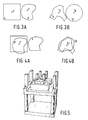
- ⁇ h and ⁇ v denote the freedom of movement of the camera 2 in a horizontal and a vertical plane. Rotation of the camera 2 around the scanning direction is referred to as angle ⁇ , the distance between the object 1 and the camera 2 being denoted by the reference ⁇ . Deviations from the optical axis of the camera 2 and the scanning direction towards the centre of the object 1 are referred to as ⁇ h and ⁇ v . In Fig. 2, ⁇ h and ⁇ v are equal to zero and not shown.
- Variations of ⁇ h , ⁇ v and ⁇ produce, substantially independently of the shape of the object 1, characteristic changes in the number of different pixels between the desired and the variable image.
- a strong relationship exists between the pick-up direction (scanning direction) of the camera 2 and the centre of gravity in its image. For small changes this is a substantially linear dependency.
- the area of an image is closely related to the squared inverse of the distance ⁇ between the camera 2 and the object 1. For small variations of ⁇ , the deviation becomes zero.
- Changes in ⁇ h , ⁇ v and ⁇ produce a characteristic change of the surface area of the modulo-2 subtraction of the desired and the variable image, resembling the "absolute" function. Three samples which are not all situated on the same side of the minimum are required to determine the parameters. A suitable rough estimate of the minimum can then be immediately found.
- the camera 2 projects this on a two-dimensional surface.
- This image is mapped on a list of global features. If the total mapping function is unique for each point within a limited domain, an inverse function of the image exists within this area.
- the inverse can be found by inverting each of the three steps. These steps are known as geometric rules but are very difficult to invert explicitly. Like Fourier transformations, they combine information and distribute information, be it in a very complex and non-linear fashion. The inverse can be approximated by the explicit storage of the relations between samples in the location and feature space.
- sample density is limited by storage capacity, search time and time available for linking elements in the two spaces by means of a model program or by operation of the robot 10.
- An important improvement of this approximation of the inverse function can be achieved when it is considered that in this particular case movement in the location space is possible by means of a robot 10 or a model program and that small changes in the location space correspond to a small change of feature values.
- a part of the points in B in Fig. 3a will be situated within the area A, referred to as B' in Fig. 4a, for which recognition is ensured in Fig. 4b. Therefore, the area in which the desired location will be found is increased by R at the expense of a detection in the feature space of Fig. 3b and a movement in the location space in Fig. 3a to Fig. 4a. In this case the detection requires knowledge of an additional location-feature relation between P and f p in the Figs. 3a, b. Fig. 4b shows the feature space after movement.
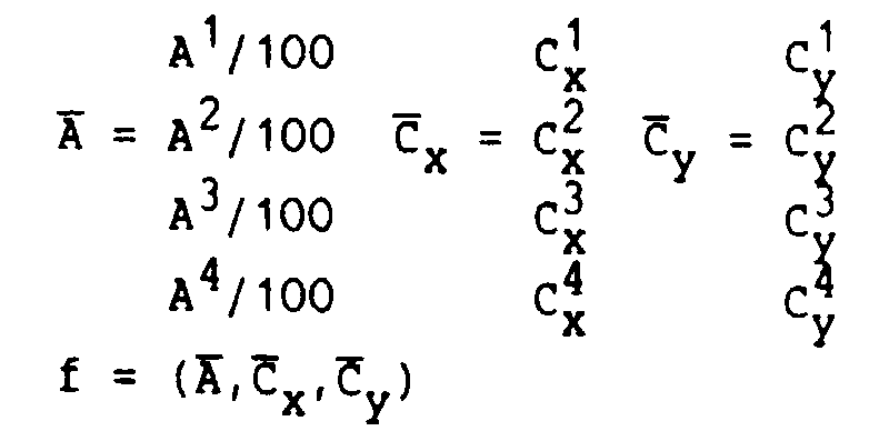
- a tot. A .(1111)
- R angle of longest axial line.
- C tot. y A T . C y
- C tot. x A T . C x A tot.
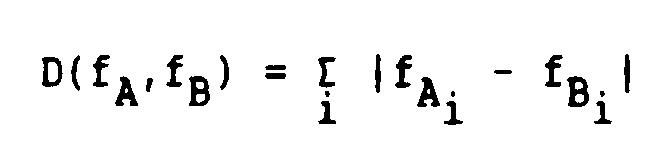
- the distance calculation for features is defined as follows: where i is a component index.
- Fig. 6 is a survey of the behaviour of the feature recognition method for the industrial object shown in Fig. 5. Relations between the camera 2 and the object 1 have been simulated for ⁇ h and ⁇ v which extend from -88 to +88 degrees in intervals of eight degrees. Boxed numbers in Fig. 6 indicate positions whose global features are known in advance. The other positions exhibit a classification on the basis of the known reference point having the smallest feature distance. Subsequently, in accordance with the foregoing general explanation, for one position which is denoted by a given number the same movement is performed as would be required to move to the origin from a position bearing the same number but being boxed.
- variable image and desired image there is associated a finite set of groups of parameters, ⁇ h , ⁇ v , ⁇ , ⁇ , ⁇ h and ⁇ v , for at least two parameters, for example ⁇ h and ⁇ v , a number of global features, for example the surfaces and centres of gravities of four quadrants of two-dimensional images, for example black-white silhouettes, the origin of the four quadrants being the overall centre of gravity of the two-dimensional image, of variable images associated with a number of reference pairs of each time one of the parameters, for example ( ⁇ h , ⁇ v ) in the range (-88°+88°) (-88° - +88°) are determined in discrete steps of 8°.
- step-wise changes are required to obtain the desired image from the variable image associated with a reference pair.
- a strategy for determining useful positions of the known points is to plot a number thereof initially at exponentially increasing distances on the virtual X and Y axis in Fig. 6. Subsequently, a simulation indicates that additional points are required (in this case two), i.e. the boxed numbers 17 and 18 in addition to the boxed numbers 1-16 initially chosen.
- the industrial object of Fig. 5 has a rotational symmetry of 180° so that the maximum size of the convergence areas is 90° (rotation in any arbitrary direction).
- the nearest diverging location is situated 80° from the origin.
- a convergence is obtained as from 24 degrees.
- the robot 10 moves quickly and smoothly to its destinations.
- Experimental results have demonstrated that it is very well possible to calculate relative locations from global features of multiple images without accurate recognition of object parts.
- visual feedbacks and deviations in the remainder of the control loop are reduced.
- Fig. 7 shows a device in accordance with the invention.
- An image generator BG (for example, a camera or a computer simulating an image) generates an image of an object OB. This image is stored in a memory M, preferably a RAM (Random Access Memory). Between BG and M there could be inserted an A/D converter, but an operational amplifier and a given threshold voltage are also suitable for digitizing the image.
- a reference image generator RG generates a reference image of the object OB: the desired two-dimensional image.
- a processor ⁇ P being connected to RG and M, determines global features of the two images and of their difference image. On the basis thereof the processor ⁇ P supplies the image generator BG with an adjustment signal VS.
- the reference image generator RG is suitable for receiving a reference image from the image generator BG.
- the reference generator RG is formed, for example by a RAM which stores the reference image.
Landscapes
- Engineering & Computer Science (AREA)
- Computer Vision & Pattern Recognition (AREA)
- Theoretical Computer Science (AREA)
- Medical Informatics (AREA)
- Health & Medical Sciences (AREA)
- Databases & Information Systems (AREA)
- Evolutionary Computation (AREA)
- General Health & Medical Sciences (AREA)
- Artificial Intelligence (AREA)
- Software Systems (AREA)
- Computing Systems (AREA)
- Physics & Mathematics (AREA)
- General Physics & Mathematics (AREA)
- Multimedia (AREA)
- Image Analysis (AREA)
- Image Processing (AREA)
- Manipulator (AREA)
- Length Measuring Devices By Optical Means (AREA)
Description
Atot. =
Claims (13)
- A method of matching a variable two-dimensional image of a known three-dimensional object with a desired two-dimensional image of that object by step-wise changing the variable image in the case of non-correspondence between the images,
characterized in that global features in the images and/or global features of the modulo-2 subtraction of the images are used to calculate a scalar global parameter as a measure of conformance between the two images, and therefrom to determine a desired step-wise change of the variable image as being governed by motion in three dimensions in order to obtain a new variable image, until a final step brings about a sufficiently conforming match. - A method as claimed in Claim 1, characterized in that the images are binary silhouettes.
- A method as claimed in Claim 1 or 2, characterized in that the variable image is supplied by an image sensor.
- A method as claimed in Claim 1 or 2, characterized in that the variable image is supplied by a computer program which provides an image picked up as if it were by an image sensor.
- A method as claimed in Claim 3, characterized in that the image sensor is accommodated in a grip which is adapted to grip the object.
- A method as claimed in Claim 5, characterized in that a new variable image is obtained by displacement in space of the grip on the basis of the determined desired step-wise change of the variable image.
- A method as claimed in Claim 4, characterized in that a new variable image is formed by the computer program by changing the virtual location of the image sensor or the object.
- A method as claimed in any one of the preceding Claims, characterized in that the desired image is provided by an image sensor.
- A method as claimed in any one of the Claims 2 to 8, characterized in that the global image features comprise a surface or centre of gravity of the silhouette.
- A method as claimed in Claim 9, characterized in that the global image features comprise the surfaces and centres of gravity of four quadrants of the silhouette, the origin of the four quadrants being situated in the overall centre of gravity of the silhouette.
- A method as claimed in any one of the preceding Claims, characterized in that a scalar minimisation algorithm is used to determine the step-wise change of the variable image.
- A method as claimed in Claim 10, characterized in that the scalar minimisation algorithm is a simplex algorithm where the simplex is the simplest geometric structure containing an N-dimensional volume.
- A method as claimed in any one of the preceding Claims, where a finite set of groups of parameters is associated with each image, characterized in that for at least two parameters there are determined a number of global features of variable images associated with a number of reference pairs of each time one of the parameters, it being known which step-wise changes are required to obtain the desired image from the variable image associated with a reference pair, the variable images associated with all remaining pairs being compared with those associated with the reference pairs, the remaining pairs respectively being classified as the reference pair of the variable image with which they correspond best, and in order to obtain a new variable image, starting from a current variable image, the step-wise changes being executed which are necessary and known to obtain the desired image from the variable image added to the current variable image and associated with the reference pair which is the classification of the remaining pair associated with the current image.
Applications Claiming Priority (2)
| Application Number | Priority Date | Filing Date | Title |
|---|---|---|---|
| NL8902611 | 1989-10-23 | ||
| NL8902611A NL8902611A (en) | 1989-10-23 | 1989-10-23 | METHOD OF BRINGING A VARIABLE TWO-DIMENSIONAL IMAGE OF THE OBJECT IN ACCORDANCE WITH A DESIRED TWO-DIMENSIONAL IMAGE OF A KNOWN THREE-DIMENSIONAL OBJECT. |
Publications (2)
| Publication Number | Publication Date |
|---|---|
| EP0425036A1 EP0425036A1 (en) | 1991-05-02 |
| EP0425036B1 true EP0425036B1 (en) | 1998-02-25 |
Family
ID=19855494
Family Applications (1)
| Application Number | Title | Priority Date | Filing Date |
|---|---|---|---|
| EP90202802A Expired - Lifetime EP0425036B1 (en) | 1989-10-23 | 1990-10-19 | Method of matching a variable two-dimensional image of a known three-dimensional object with a desired two-dimensional image of the object |
Country Status (5)
| Country | Link |
|---|---|
| EP (1) | EP0425036B1 (en) |
| JP (1) | JPH03196374A (en) |
| KR (1) | KR910009058A (en) |
| DE (1) | DE69032061T2 (en) |
| NL (1) | NL8902611A (en) |
Family Cites Families (1)
| Publication number | Priority date | Publication date | Assignee | Title |
|---|---|---|---|---|
| US4658428A (en) * | 1985-07-17 | 1987-04-14 | Honeywell Inc. | Image recognition template generation |
-
1989
- 1989-10-23 NL NL8902611A patent/NL8902611A/en not_active Application Discontinuation
-
1990
- 1990-10-19 DE DE69032061T patent/DE69032061T2/en not_active Expired - Fee Related
- 1990-10-19 EP EP90202802A patent/EP0425036B1/en not_active Expired - Lifetime
- 1990-10-22 JP JP2282042A patent/JPH03196374A/en active Pending
- 1990-10-22 KR KR1019900016856A patent/KR910009058A/en not_active Abandoned
Also Published As
| Publication number | Publication date |
|---|---|
| KR910009058A (en) | 1991-05-31 |
| DE69032061D1 (en) | 1998-04-02 |
| DE69032061T2 (en) | 1998-08-13 |
| JPH03196374A (en) | 1991-08-27 |
| EP0425036A1 (en) | 1991-05-02 |
| NL8902611A (en) | 1991-05-16 |
Similar Documents
| Publication | Publication Date | Title |
|---|---|---|
| US8792726B2 (en) | Geometric feature extracting device, geometric feature extracting method, storage medium, three-dimensional measurement apparatus, and object recognition apparatus | |
| Stoyanov et al. | Fast and accurate scan registration through minimization of the distance between compact 3D NDT representations | |
| Marton et al. | General 3D modelling of novel objects from a single view | |
| KR101925862B1 (en) | Real-time 3d mapping using 3d-lidar | |
| Rossi et al. | Tracking moving optima using Kalman-based predictions | |
| Buchholz | Bin-picking: new approaches for a classical problem | |
| US5220619A (en) | Method of matching a variable two-dimensional image of a known three-dimensional object with a desired two-dimensional image of the object, and device for carrying out the method | |
| Eggert et al. | Simultaneous registration of multiple range views for use in reverse engineering | |
| Vaskevicius et al. | Revisiting superquadric fitting: A numerically stable formulation | |
| Haidacher et al. | Estimating finger contact location and object pose from contact measurements in 3d grasping | |
| Nielsen | Robust lidar-based localization in underground mines | |
| Chen et al. | 3D object classification with point convolution network | |
| Kwon et al. | Rescan strategy for time efficient view and path planning in automated inspection system | |
| Zhao et al. | A 3D image processing method for manufacturing process automation | |
| Shmatko et al. | Estimation of rotation measurement error of objects using computer simulation | |
| EP0425036A1 (en) | Method of matching a variable two-dimensional image of a known three-dimensional object with a desired two-dimensional image of the object, and device for carrying out the method | |
| JPH07264458A (en) | Moving object tracking device | |
| Al-Temeemy et al. | Chromatic methodology for laser detection and ranging (LADAR) image description | |
| JPH10128686A (en) | Robot manipulator control method and robot manipulator control device | |
| Lourenço et al. | 2D lidar to kinematic chain calibration using planar features of indoor scenes | |
| Olson | Landmark selection for terrain matching | |
| Rink et al. | Monte Carlo registration and its application with autonomous robots | |
| Brito et al. | Using geometric interval algebra modeling for improved three-dimensional camera calibration | |
| Brown et al. | Extrinsic calibration of multiple 2D Lidars using a Genetic Algorithm: A robust method to estimate the x, y and yaw coordinates of vehicle-mounted 2D Lidars using data acquired when moving | |
| Muñoz | Global pose estimation and tracking for RGB-D localization and 3D mapping |
Legal Events
| Date | Code | Title | Description |
|---|---|---|---|
| PUAI | Public reference made under article 153(3) epc to a published international application that has entered the european phase |
Free format text: ORIGINAL CODE: 0009012 |
|
| AK | Designated contracting states |
Kind code of ref document: A1 Designated state(s): BE DE ES FR GB IT SE |
|
| 17P | Request for examination filed |
Effective date: 19911028 |
|
| 17Q | First examination report despatched |
Effective date: 19960628 |
|
| GRAG | Despatch of communication of intention to grant |
Free format text: ORIGINAL CODE: EPIDOS AGRA |
|
| GRAG | Despatch of communication of intention to grant |
Free format text: ORIGINAL CODE: EPIDOS AGRA |
|
| GRAH | Despatch of communication of intention to grant a patent |
Free format text: ORIGINAL CODE: EPIDOS IGRA |
|
| GRAH | Despatch of communication of intention to grant a patent |
Free format text: ORIGINAL CODE: EPIDOS IGRA |
|
| GRAA | (expected) grant |
Free format text: ORIGINAL CODE: 0009210 |
|
| AK | Designated contracting states |
Kind code of ref document: B1 Designated state(s): BE DE ES FR GB IT SE |
|
| PG25 | Lapsed in a contracting state [announced via postgrant information from national office to epo] |
Ref country code: IT Free format text: LAPSE BECAUSE OF FAILURE TO SUBMIT A TRANSLATION OF THE DESCRIPTION OR TO PAY THE FEE WITHIN THE PRE;WARNING: LAPSES OF ITALIAN PATENTS WITH EFFECTIVE DATE BEFORE 2007 MAY HAVE OCCURRED AT ANY TIME BEFORE 2007. THE CORRECT EFFECTIVE DATE MAY BE DIFFERENT FROM THE ONE RECORDED.SCRIBED TIME-LIMIT Effective date: 19980225 Ref country code: BE Free format text: LAPSE BECAUSE OF FAILURE TO SUBMIT A TRANSLATION OF THE DESCRIPTION OR TO PAY THE FEE WITHIN THE PRESCRIBED TIME-LIMIT Effective date: 19980225 Ref country code: ES Free format text: THE PATENT HAS BEEN ANNULLED BY A DECISION OF A NATIONAL AUTHORITY Effective date: 19980225 |
|
| REF | Corresponds to: |
Ref document number: 69032061 Country of ref document: DE Date of ref document: 19980402 |
|
| ET | Fr: translation filed | ||
| PG25 | Lapsed in a contracting state [announced via postgrant information from national office to epo] |
Ref country code: SE Free format text: LAPSE BECAUSE OF FAILURE TO SUBMIT A TRANSLATION OF THE DESCRIPTION OR TO PAY THE FEE WITHIN THE PRESCRIBED TIME-LIMIT Effective date: 19980525 |
|
| RAP4 | Party data changed (patent owner data changed or rights of a patent transferred) |
Owner name: KONINKLIJKE PHILIPS ELECTRONICS N.V. |
|
| REG | Reference to a national code |
Ref country code: FR Ref legal event code: CD |
|
| PLBE | No opposition filed within time limit |
Free format text: ORIGINAL CODE: 0009261 |
|
| STAA | Information on the status of an ep patent application or granted ep patent |
Free format text: STATUS: NO OPPOSITION FILED WITHIN TIME LIMIT |
|
| 26N | No opposition filed | ||
| PGFP | Annual fee paid to national office [announced via postgrant information from national office to epo] |
Ref country code: FR Payment date: 20001024 Year of fee payment: 11 |
|
| PGFP | Annual fee paid to national office [announced via postgrant information from national office to epo] |
Ref country code: GB Payment date: 20001101 Year of fee payment: 11 |
|
| PGFP | Annual fee paid to national office [announced via postgrant information from national office to epo] |
Ref country code: DE Payment date: 20001220 Year of fee payment: 11 |
|
| PG25 | Lapsed in a contracting state [announced via postgrant information from national office to epo] |
Ref country code: GB Free format text: LAPSE BECAUSE OF NON-PAYMENT OF DUE FEES Effective date: 20011019 |
|
| REG | Reference to a national code |
Ref country code: GB Ref legal event code: IF02 |
|
| GBPC | Gb: european patent ceased through non-payment of renewal fee |
Effective date: 20011019 |
|
| PG25 | Lapsed in a contracting state [announced via postgrant information from national office to epo] |
Ref country code: FR Free format text: LAPSE BECAUSE OF NON-PAYMENT OF DUE FEES Effective date: 20020628 |
|
| PG25 | Lapsed in a contracting state [announced via postgrant information from national office to epo] |
Ref country code: DE Free format text: LAPSE BECAUSE OF NON-PAYMENT OF DUE FEES Effective date: 20020702 |
|
| REG | Reference to a national code |
Ref country code: FR Ref legal event code: ST |