EP0424862B1 - Analoger Mehrkanalregler - Google Patents
Analoger Mehrkanalregler Download PDFInfo
- Publication number
- EP0424862B1 EP0424862B1 EP90120272A EP90120272A EP0424862B1 EP 0424862 B1 EP0424862 B1 EP 0424862B1 EP 90120272 A EP90120272 A EP 90120272A EP 90120272 A EP90120272 A EP 90120272A EP 0424862 B1 EP0424862 B1 EP 0424862B1
- Authority
- EP
- European Patent Office
- Prior art keywords
- integrator
- channel
- switch
- input
- signal
- Prior art date
- Legal status (The legal status is an assumption and is not a legal conclusion. Google has not performed a legal analysis and makes no representation as to the accuracy of the status listed.)
- Expired - Lifetime
Links
- 238000002955 isolation Methods 0.000 claims description 10
- 230000007547 defect Effects 0.000 description 4
- 230000002950 deficient Effects 0.000 description 3
- 230000000694 effects Effects 0.000 description 2
- 238000010586 diagram Methods 0.000 description 1
- 230000005611 electricity Effects 0.000 description 1
- 230000010354 integration Effects 0.000 description 1
- 230000007257 malfunction Effects 0.000 description 1
Images


Classifications
-
- G—PHYSICS
- G05—CONTROLLING; REGULATING
- G05B—CONTROL OR REGULATING SYSTEMS IN GENERAL; FUNCTIONAL ELEMENTS OF SUCH SYSTEMS; MONITORING OR TESTING ARRANGEMENTS FOR SUCH SYSTEMS OR ELEMENTS
- G05B9/00—Safety arrangements
- G05B9/02—Safety arrangements electric
- G05B9/03—Safety arrangements electric with multiple-channel loop, i.e. redundant control systems
-
- G—PHYSICS
- G05—CONTROLLING; REGULATING
- G05B—CONTROL OR REGULATING SYSTEMS IN GENERAL; FUNCTIONAL ELEMENTS OF SUCH SYSTEMS; MONITORING OR TESTING ARRANGEMENTS FOR SUCH SYSTEMS OR ELEMENTS
- G05B7/00—Arrangements for obtaining smooth engagement or disengagement of automatic control
- G05B7/02—Arrangements for obtaining smooth engagement or disengagement of automatic control electric
Definitions
- the invention relates to a digital or analog multichannel controller with at least two redundant channels, each with an integrator, the same control deviation signal being able to be connected to the respective integrator separately for each channel.
- a multi-channel controller is known from EP 0318006 A2.
- the input signals of the controllers are deviation signals, i. H. Those that have been formed by forming a difference between a setpoint and an actual value. It is essential that there is always only one channel in engagement, i.e. That is, only its deviation signal is processed further to a control signal via the controller.
- the other channels are supplied with electricity, but their control signals are switched off by a channel switchover logic.
- a special embodiment of such a multi-channel analog controller is a redundant controller, in which preferably two, but also several controller channels are provided, which should have essentially the same signal. Such controllers are required where the failure of one controller would have unacceptable consequences, and can therefore be switched to the second channel if one channel is defective.
- the integrators of the channel that is not in engagement have run into positive or negative saturation, since in practice a complete match of the input channels is not guaranteed. Since the integrator which is not in engagement there is not tracked to the value of the active integrator, but rather to the overall level, a smooth switchover is not possible, and in such a case the switch is made to the other channel, so the signal jump generally leads to the Saturation value of the newly added integrator an interference pulse in the control system.
- the object of the present invention is to design a generic analog multi-channel controller in such a way that such interference pulses are avoided in the control system, i. H. a smooth switchover is possible.
- the main advantage of the controller according to the invention is that the integrator which is not in engagement does not run into saturation, but is carried along with the integrator output which is in engagement, so that no signal pulse occurs when switching from one integrator to the other. This advantageously prevents a malfunction in the control system during the switchover.
- a summator is assigned to the integrator not in engagement, the output of the summator acting on the input of the integrator.
- the integrator output signal of the integrator in engagement is applied to the plus input of the summer, while the output of the assigned integrator is fed to the minus input.
- the integrator forms a first-order delay element (PT 1 element) for the output signal of the integrator in engagement.
- PT 1 element first-order delay element
- the switchover from one channel to the other is achieved by simultaneously switching the switches of the two integrators, so that the input of the integrator which has been in use until now is switched from the signal deviation input signal to the output of the assigned summer, so that the integrator thus formed Loop becomes a first order delay element for the signals at the plus input of this summer.
- the input of the integrator, which was previously out of engagement is switched off from the output of the assigned summer and connected to the assigned input channel with its deviation signal. This integrator takes over the further regulation.
- isolation amplifiers for electrical isolation are provided between the outputs of the integrators and the inputs of the non-assigned summers.
- differential amplifiers can be provided for high-resistance decoupling. This ensures complete galvanic decoupling of the individual channels from one another, so that a component defect in one channel cannot necessarily have any effect on the other channel or channels.
- the analog two-channel controller 1 shown in FIG. 1 has two inputs 2a, b, which are acted upon by control deviation signals of the two channels I and II. These control deviation signals are usually formed by forming a difference between a setpoint and the associated actual value.
- the two inputs 2a, b are connected to two switches 3a, 3b, which are switched together, what is indicated by the dashed line 4.
- the changeover switches 3a, b can be designed as mechanical or electronic switches, the latter being preferred because the switching speed is higher and the probability of failure is lower.
- the two changeover switches 3a, b are connected to two control amplifiers 5a, 5b, which have integral behavior, in particular those with I, PI, PID behavior.
- the outputs of these control amplifiers 5a, b, hereinafter referred to as integrators, are combined in a merging unit 6 to form an actuating signal 7.
- This merging unit 6 is designed as a changeover switch for switching through one of the two integrators 5a, b.
- the outputs of the integrators 5a, b are connected to negative inputs of two respectively assigned summers 8a, b and, in parallel, to the inputs of two isolating amplifiers 9a, b.
- the outputs of the isolation amplifiers 9b, a of the respective other integrator 5b, a are fed to the plus input of the summer 8a, b.
- the outputs of the summers 8a, b are connected to the respective second switching inputs of the changeover switches 3a, b.
- channel I In the position shown in FIG. 1, channel I is in engagement, ie the control deviation signal located at input 2a is switched through as an actuating signal 7 via integrator 5a and merging unit 6.
- the changeover switch 3b is in a position in which the associated input 2b is decoupled from the integrator 5b.
- the input of this integrator 5b is connected to the output of the assigned summer 8b.
- the loop formed between the integrator 5b and the associated summer 8b forms a first-order delay element (PT 1) for the signal supplied in the positive input of the summer 8b.
- an input 2c is provided for channel III. Any number of additional channels could be connected in the same way.
- the input 2c is connected via a changeover switch 3c to the integrator 5c, the output of which in turn u. a. applied to an assigned summer 8c.
- This summer 8c has a plurality of plus inputs and a minus input. The minus input is connected to the output of the associated integrator 5c, while the plus inputs are connected to the outputs of the other integrators 5a, b via the switches 10a, b.
- Switch 10a which is coupled to the integrator currently in engagement, is closed, while switch 10b of another integrator which is not in engagement is open, so that its signal is not applied to summer 8c.
- the output of the integrator 5c shown comprises a switch 10c in order to switch its output signal to the assigned summers 8a, b of the other channels when the integrator 5c is in engagement.
- the switches 3c and 10c are preferably controlled together.
- the output signal is also fed behind the switch 10c to the merging unit 6, whereby since only one of the switches 10a, b, c is always switched through, only one signal is present at the merging unit 6.
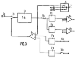
- FIG. 3 an embodiment of a channel is shown, which differs from the embodiment of FIG. 2 in that isolation amplifiers 9a ', 9b' and 9c 'are switched on in the signal flow. Namely, the two isolation amplifiers 9c 'are connected between the switch 10c and the inputs of the summers 8a and 8b of the other channels.
- the isolation amplifier 9a ' is actually assigned to the channel I (which is shown in all figures as being in engagement), and analogously couples the output signal of the integrator 5a (FIG. 1) via the closed switch 10a to a plus input of the summer 8c. It is the same with the isolation amplifier 9'b.
Landscapes
- Physics & Mathematics (AREA)
- General Physics & Mathematics (AREA)
- Engineering & Computer Science (AREA)
- Automation & Control Theory (AREA)
- Safety Devices In Control Systems (AREA)
Applications Claiming Priority (2)
| Application Number | Priority Date | Filing Date | Title |
|---|---|---|---|
| DE3935958 | 1989-10-27 | ||
| DE3935958A DE3935958A1 (de) | 1989-10-27 | 1989-10-27 | Analoger mehrkanalregler |
Publications (3)
| Publication Number | Publication Date |
|---|---|
| EP0424862A2 EP0424862A2 (de) | 1991-05-02 |
| EP0424862A3 EP0424862A3 (en) | 1991-10-16 |
| EP0424862B1 true EP0424862B1 (de) | 1995-06-21 |
Family
ID=6392432
Family Applications (1)
| Application Number | Title | Priority Date | Filing Date |
|---|---|---|---|
| EP90120272A Expired - Lifetime EP0424862B1 (de) | 1989-10-27 | 1990-10-23 | Analoger Mehrkanalregler |
Country Status (3)
| Country | Link |
|---|---|
| US (1) | US5148364A (https=) |
| EP (1) | EP0424862B1 (https=) |
| DE (2) | DE3935958A1 (https=) |
Families Citing this family (15)
| Publication number | Priority date | Publication date | Assignee | Title |
|---|---|---|---|---|
| JP3524936B2 (ja) * | 1992-01-15 | 2004-05-10 | キャタピラー インコーポレイテッド | 油圧駆動車両用の冗長制御装置 |
| US5452200A (en) * | 1993-10-20 | 1995-09-19 | United Technologies Corporation | Control system that selects proportional-integral control channels having integrator update capability |
| US5987888A (en) * | 1997-07-15 | 1999-11-23 | Detroit Diesel Corporation | System and method for controlling a turbocharger |
| US6000221A (en) * | 1997-11-04 | 1999-12-14 | Detroit Diesel Corporation | System for controlling a variable geometry turbocharger |
| US6055812A (en) * | 1998-12-08 | 2000-05-02 | Detroit Diesel Corporation | System and method for controlling a sequential turbocharging system |
| US6134889A (en) * | 1999-04-28 | 2000-10-24 | Detroit Diesel Corporation | Variable geometry turbocharging system and method |
| US6885743B2 (en) * | 2001-01-16 | 2005-04-26 | Lucent Technologies Inc. | Software circuit switching router using anchor channels |
| DE102004058328A1 (de) * | 2004-12-02 | 2006-06-08 | Framatome Anp Gmbh | Regeleinrichtung |
| US8718799B2 (en) * | 2008-05-12 | 2014-05-06 | Ge Fanuc Intelligent Platforms, Inc. | Method and system for process control configuration changes |
| DE102011080989B4 (de) | 2011-08-16 | 2013-12-12 | Mtu Friedrichshafen Gmbh | Steuereinrichtung für ein Einspritzsystem, Einspritzsystem mit einer Brennkraftmaschine und Notstromaggregat |
| DE102011080986B4 (de) | 2011-08-16 | 2014-02-13 | Mtu Friedrichshafen Gmbh | Steuereinrichtung für ein Einspritzsystem, Einspritzsystem mit einer Brennkraftmaschine und Notstromaggregat |
| CN105717844A (zh) * | 2016-03-29 | 2016-06-29 | 中国计量学院 | 多功能信号采集仪 |
| US10795323B2 (en) | 2018-09-06 | 2020-10-06 | Rolls-Royce North American Technologies, Inc. | Symbiotic control loop |
| US11491930B2 (en) * | 2019-12-03 | 2022-11-08 | Woodward, Inc. | Systems and methods for commanded or uncommanded channel switchover in a multiple processor controller |
| JP7378380B2 (ja) * | 2020-11-04 | 2023-11-13 | 株式会社日立製作所 | 比例積分制御装置並びに比例積分制御方法 |
Family Cites Families (8)
| Publication number | Priority date | Publication date | Assignee | Title |
|---|---|---|---|---|
| GB1182268A (en) * | 1966-11-17 | 1970-02-25 | Elliott Brothers London Ltd | Improvements in or relating to Aircraft Control Systems. |
| DE2235307A1 (de) * | 1971-07-31 | 1973-02-08 | Autologic Ltd | Steuersystem zur positionierung eines bewegten objektes, insbesondere des werkzeuges bzw. des werkzeugtraegers einer werkzeugmaschine |
| JPS573101A (en) * | 1980-06-09 | 1982-01-08 | Hitachi Ltd | Multiple control device |
| US4562528A (en) * | 1982-10-06 | 1985-12-31 | Mitsubishi Denki Kabushiki Kaisha | Backup control apparatus |
| US4560319A (en) * | 1983-08-01 | 1985-12-24 | MAN Maschinenfabrik Unternehmensbereich GHH Sterkrade | Method and apparatus for controlling at least two parallel-connected turbocompressors |
| JPS6086602A (ja) * | 1983-10-18 | 1985-05-16 | Mitsubishi Electric Corp | 多重化制御方式 |
| JPH0673081B2 (ja) * | 1987-11-25 | 1994-09-14 | 株式会社日立製作所 | 自動制御装置 |
| JPH01245335A (ja) * | 1988-03-28 | 1989-09-29 | Hitachi Ltd | プログラマブルコントローラの多重化システム |
-
1989
- 1989-10-27 DE DE3935958A patent/DE3935958A1/de active Granted
-
1990
- 1990-10-23 EP EP90120272A patent/EP0424862B1/de not_active Expired - Lifetime
- 1990-10-23 DE DE59009284T patent/DE59009284D1/de not_active Expired - Fee Related
- 1990-10-26 US US07/604,826 patent/US5148364A/en not_active Expired - Fee Related
Also Published As
| Publication number | Publication date |
|---|---|
| US5148364A (en) | 1992-09-15 |
| EP0424862A3 (en) | 1991-10-16 |
| EP0424862A2 (de) | 1991-05-02 |
| DE3935958C2 (https=) | 1991-11-07 |
| DE59009284D1 (de) | 1995-07-27 |
| DE3935958A1 (de) | 1991-05-02 |
Similar Documents
| Publication | Publication Date | Title |
|---|---|---|
| EP0424862B1 (de) | Analoger Mehrkanalregler | |
| DE3708266A1 (de) | Servosystem mit nachfuehrung | |
| EP0625463A1 (de) | Kabinendruckregelanlage für Flugzeuge | |
| DE3432165C2 (https=) | ||
| EP1119799B1 (de) | Regeleinrichtung zur regelung einer strecke mit mehreren verkoppelten regelgrössen | |
| DE3100126C2 (de) | Regler mit einem Sollwert/Istwert-Vergleichsorgan | |
| DE2453011A1 (de) | Verfahren und schaltungsanordnung zur auswahl eines signals aus wenigstens drei redundanten signalkanaelen | |
| DE3887466T2 (de) | Automatische Steuerungseinrichtung. | |
| DE1588149A1 (de) | Mehrfachkanal-Servosystem | |
| WO1998004963A1 (de) | Pid-regler mit schutz des integrators vor sättigung bei schneller änderung der führungsgrösse | |
| DE69110546T2 (de) | Vorrichtung zur Erzeugung eines der Eingangsgrösse der Vorrichtung entsprechenden Stromes. | |
| DE3522220A1 (de) | Anordnung zur ausgabe von steuersignalen an stellelemente eines prozesses | |
| DE102020124731B4 (de) | Verfahren zum Betreiben eines Fluggeräts, Regelungsarchitektur für ein Fluggerät und Fluggerät mit einer solchen | |
| EP0113379A1 (de) | Rechnerkopplung | |
| DE4408603A1 (de) | Verfahren zur Erhöhung der Sicherheit in hierarchisch strukturierten Automatisierungssystemen | |
| DE69212740T2 (de) | Drei-Eingänge-Signal Auswähler, angewendet auf einen N-Eingänge-Auswähler und eine N-Eingänge Abstimmungsschaltung | |
| EP0997813A2 (de) | Schaltungsanordnung zum Verarbeiten binärer Signale | |
| EP1817645B1 (de) | Regeleinrichtung | |
| EP0304453B1 (de) | Digitales integriermodul für abtastregeleinrichtungen | |
| EP0303065B1 (de) | Verfahren und Schaltungsanordnung für Halbleiterbausteine mit in hochintegrierter Schaltkreistechnik zusammengefassten logischen Verknüpfungsschaltungen | |
| DE69006903T2 (de) | Überwachungsanordnung für ein elektrisches variables Signal und Bauteil dafür. | |
| DE4303048A1 (en) | Alarm recognition apparatus for redundant layout circuit in radio equipment - has input circuits delaying alarm recognition signals when circuits are switched to be operational systems | |
| EP4480781A1 (de) | Eisenbahngleisanlage mit schnittstelleneinrichtung und verfahren zu deren betrieb | |
| DE19919595A1 (de) | Regeleinrichtung zur Regelung einer Strecke mit mehreren verkoppelten Regelgrößen | |
| DE1927392A1 (de) | Stetiger elektrischer Regler mit kontinuierlicher Ausgangsgroesse zur Betaetigung proportional wirkender Stellgllieder |
Legal Events
| Date | Code | Title | Description |
|---|---|---|---|
| PUAI | Public reference made under article 153(3) epc to a published international application that has entered the european phase |
Free format text: ORIGINAL CODE: 0009012 |
|
| AK | Designated contracting states |
Kind code of ref document: A2 Designated state(s): DE FR GB IT |
|
| PUAL | Search report despatched |
Free format text: ORIGINAL CODE: 0009013 |
|
| AK | Designated contracting states |
Kind code of ref document: A3 Designated state(s): DE FR GB IT |
|
| 17P | Request for examination filed |
Effective date: 19911106 |
|
| 17Q | First examination report despatched |
Effective date: 19930714 |
|
| ITF | It: translation for a ep patent filed | ||
| GRAA | (expected) grant |
Free format text: ORIGINAL CODE: 0009210 |
|
| AK | Designated contracting states |
Kind code of ref document: B1 Designated state(s): DE FR GB IT |
|
| REF | Corresponds to: |
Ref document number: 59009284 Country of ref document: DE Date of ref document: 19950727 |
|
| ET | Fr: translation filed | ||
| PG25 | Lapsed in a contracting state [announced via postgrant information from national office to epo] |
Ref country code: GB Effective date: 19951023 |
|
| GBT | Gb: translation of ep patent filed (gb section 77(6)(a)/1977) |
Effective date: 19950922 |
|
| PLBE | No opposition filed within time limit |
Free format text: ORIGINAL CODE: 0009261 |
|
| STAA | Information on the status of an ep patent application or granted ep patent |
Free format text: STATUS: NO OPPOSITION FILED WITHIN TIME LIMIT |
|
| 26N | No opposition filed | ||
| GBPC | Gb: european patent ceased through non-payment of renewal fee |
Effective date: 19951023 |
|
| PG25 | Lapsed in a contracting state [announced via postgrant information from national office to epo] |
Ref country code: FR Effective date: 19960628 |
|
| PG25 | Lapsed in a contracting state [announced via postgrant information from national office to epo] |
Ref country code: DE Effective date: 19960702 |
|
| REG | Reference to a national code |
Ref country code: FR Ref legal event code: ST |
|
| PG25 | Lapsed in a contracting state [announced via postgrant information from national office to epo] |
Ref country code: IT Free format text: LAPSE BECAUSE OF NON-PAYMENT OF DUE FEES;WARNING: LAPSES OF ITALIAN PATENTS WITH EFFECTIVE DATE BEFORE 2007 MAY HAVE OCCURRED AT ANY TIME BEFORE 2007. THE CORRECT EFFECTIVE DATE MAY BE DIFFERENT FROM THE ONE RECORDED. Effective date: 20051023 |