EP0424509B1 - Short-range radar transceiver employing a fet oscillator - Google Patents
Short-range radar transceiver employing a fet oscillator Download PDFInfo
- Publication number
- EP0424509B1 EP0424509B1 EP90907667A EP90907667A EP0424509B1 EP 0424509 B1 EP0424509 B1 EP 0424509B1 EP 90907667 A EP90907667 A EP 90907667A EP 90907667 A EP90907667 A EP 90907667A EP 0424509 B1 EP0424509 B1 EP 0424509B1
- Authority
- EP
- European Patent Office
- Prior art keywords
- signal
- radar transceiver
- antenna
- oscillator
- range
- Prior art date
- Legal status (The legal status is an assumption and is not a legal conclusion. Google has not performed a legal analysis and makes no representation as to the accuracy of the status listed.)
- Expired - Lifetime
Links
Images

Classifications
-
- G—PHYSICS
- G01—MEASURING; TESTING
- G01S—RADIO DIRECTION-FINDING; RADIO NAVIGATION; DETERMINING DISTANCE OR VELOCITY BY USE OF RADIO WAVES; LOCATING OR PRESENCE-DETECTING BY USE OF THE REFLECTION OR RERADIATION OF RADIO WAVES; ANALOGOUS ARRANGEMENTS USING OTHER WAVES
- G01S13/00—Systems using the reflection or reradiation of radio waves, e.g. radar systems; Analogous systems using reflection or reradiation of waves whose nature or wavelength is irrelevant or unspecified
- G01S13/02—Systems using reflection of radio waves, e.g. primary radar systems; Analogous systems
- G01S13/06—Systems determining position data of a target
- G01S13/08—Systems for measuring distance only
- G01S13/32—Systems for measuring distance only using transmission of continuous waves, whether amplitude-, frequency-, or phase-modulated, or unmodulated
- G01S13/34—Systems for measuring distance only using transmission of continuous waves, whether amplitude-, frequency-, or phase-modulated, or unmodulated using transmission of continuous, frequency-modulated waves while heterodyning the received signal, or a signal derived therefrom, with a locally-generated signal related to the contemporaneously transmitted signal
-
- G—PHYSICS
- G01—MEASURING; TESTING
- G01S—RADIO DIRECTION-FINDING; RADIO NAVIGATION; DETERMINING DISTANCE OR VELOCITY BY USE OF RADIO WAVES; LOCATING OR PRESENCE-DETECTING BY USE OF THE REFLECTION OR RERADIATION OF RADIO WAVES; ANALOGOUS ARRANGEMENTS USING OTHER WAVES
- G01S7/00—Details of systems according to groups G01S13/00, G01S15/00, G01S17/00
- G01S7/02—Details of systems according to groups G01S13/00, G01S15/00, G01S17/00 of systems according to group G01S13/00
- G01S7/03—Details of HF subsystems specially adapted therefor, e.g. common to transmitter and receiver
- G01S7/032—Constructional details for solid-state radar subsystems
-
- G—PHYSICS
- G01—MEASURING; TESTING
- G01S—RADIO DIRECTION-FINDING; RADIO NAVIGATION; DETERMINING DISTANCE OR VELOCITY BY USE OF RADIO WAVES; LOCATING OR PRESENCE-DETECTING BY USE OF THE REFLECTION OR RERADIATION OF RADIO WAVES; ANALOGOUS ARRANGEMENTS USING OTHER WAVES
- G01S7/00—Details of systems according to groups G01S13/00, G01S15/00, G01S17/00
- G01S7/02—Details of systems according to groups G01S13/00, G01S15/00, G01S17/00 of systems according to group G01S13/00
- G01S7/024—Details of systems according to groups G01S13/00, G01S15/00, G01S17/00 of systems according to group G01S13/00 using polarisation effects
- G01S7/026—Details of systems according to groups G01S13/00, G01S15/00, G01S17/00 of systems according to group G01S13/00 using polarisation effects involving the transmission of elliptically or circularly polarised waves
-
- H—ELECTRICITY
- H01—ELECTRIC ELEMENTS
- H01Q—ANTENNAS, i.e. RADIO AERIALS
- H01Q1/00—Details of, or arrangements associated with, antennas
- H01Q1/12—Supports; Mounting means
- H01Q1/22—Supports; Mounting means by structural association with other equipment or articles
- H01Q1/24—Supports; Mounting means by structural association with other equipment or articles with receiving set
- H01Q1/247—Supports; Mounting means by structural association with other equipment or articles with receiving set with frequency mixer, e.g. for direct satellite reception or Doppler radar
-
- H—ELECTRICITY
- H01—ELECTRIC ELEMENTS
- H01Q—ANTENNAS, i.e. RADIO AERIALS
- H01Q21/00—Antenna arrays or systems
- H01Q21/06—Arrays of individually energised antenna units similarly polarised and spaced apart
- H01Q21/061—Two dimensional planar arrays
- H01Q21/065—Patch antenna array
-
- H—ELECTRICITY
- H01—ELECTRIC ELEMENTS
- H01Q—ANTENNAS, i.e. RADIO AERIALS
- H01Q21/00—Antenna arrays or systems
- H01Q21/24—Combinations of antenna units polarised in different directions for transmitting or receiving circularly and elliptically polarised waves or waves linearly polarised in any direction
-
- H—ELECTRICITY
- H01—ELECTRIC ELEMENTS
- H01Q—ANTENNAS, i.e. RADIO AERIALS
- H01Q9/00—Electrically-short antennas having dimensions not more than twice the operating wavelength and consisting of conductive active radiating elements
- H01Q9/04—Resonant antennas
- H01Q9/0407—Substantially flat resonant element parallel to ground plane, e.g. patch antenna
- H01Q9/0428—Substantially flat resonant element parallel to ground plane, e.g. patch antenna radiating a circular polarised wave
- H01Q9/0435—Substantially flat resonant element parallel to ground plane, e.g. patch antenna radiating a circular polarised wave using two feed points
Definitions
- This invention relates to radar, and more particularly to radar transceivers for short-range target detection.
- FMCW radar systems using solid state components are commonly found in short-range radar detection applications.
- Prior art FMCW radar transceivers have been based on microwave power sources such as a vacuum tube, typically a klystron, or a transferred electron device such as a Gunn diode. These conventional approaches do not lend themselves to monolithic circuit fabrication techniques which are ideal for high production implementation.
- the radar transceiver is hybrid integrated and is fabricated on a single substrate such as a Duroid substrate (Duroid is a registered trademark of Rogers Corporation).
- a voltage controlled Gunn oscillator is suggested as the transmitter oscillator which, as noted above, does not lend itself to monolithic circuit fabrication techniques. Specific fabrication techniques are not described with respect to the oscillator.
- Solid state devices such as FET's and IMPATT diodes are capable of generating power at millimeter-wave frequencies. Both of these however, have inherent problems which limit their usefulness. FET oscillators provide relatively low power and produce high 1/F noise. Additionally, they are limited to the lower millimeter-wave frequencies, but IMPATTS exhibit high AM noise which degrades system noise performance.”
- the circuit comprises a field effect transistor oscillator means for generating a time varying signal, antenna means for transmitting signals to a target and for receiving signals reflected from the target, means for coupling the time varying signal to the antenna means, a mixer having a first port for receiving the time varying signal and a second port for receiving signals from the antenna means for producing an intermediate frequency signal, and signal processing means responsive to the intermediate frequency signal for producing indications of the range and/or the rate of change of the range of the target.
- This system is provided for operation at longer ranges.
- This invention provides a FET oscillator-based FMCW radar transceiver which is ideally suited for short-range target detection applications.
- the radar transceiver comprises a FET voltage controlled oscillator and a balanced mixer.
- One embodiment employs separate microstrip transmitting and receiving antennas, and a second embodiment employs a circulatorless, circularly polarized microstrip integrated antenna.
- a digital signal processor with a range gate receives a digitized IF signal and is employed to identify the targets and the target velocities.
- the FET oscillator was considered unsuitable for short-range radar applications because of the excessive up-converted 1/f noise.
- the self-correlation nature of this FMCW radar transceiver combined with the AM noise suppression of the balanced mixer enables the fabrication of a low-cost radar sensor using well-established monolithic integrated circuit technology.
- This solid state FMCW radar transceiver for short-range applications provides improvements over prior art arrangements for such applications because it offers the advantages of durability, small size, lightweight, and is adaptable to low-cost manufacturing while still providing or retaining the ability to penetrate fog, dust, and smoke.
- the radar transceiver system is a simple motion detector if the transmitter frequency remains constant.
- the radio frequency (RF) transmitter power and the local oscillator (LO) drive for the mixer stage are provided by a common voltage controlled oscillator (VCO) which is a FET oscillator.
- VCO voltage controlled oscillator
- This microwave integrated circuit FMCW radar transceiver operates with a circularly polarized waveform. Such a waveform is particularly attractive for automotive "rearview mirror" and short-range collision avoidance applications because the antenna required uses directional couplers in place of non-reciprocal elements such as circulators, which are required in conventional radars.
- the FET based microwave monolithic integrated circuit is ideally suited for short-range applications where durability, low cost, compact size, light weight, and high volume production are essential.
- this promising technology has not been incorporated into radar sensor designs because the FET oscillator was considered to be too noisy for any radar application.
- We have determined that the noise characteristics of a FET oscillator will not cause serious performance degradation if a single RF signal source is used in a short-range radar transceiver. Consequently, the FET based monolithic integrated radar transceiver is ideal for use in short-range applications.
- the Gunn diode (transferred electron device) oscillator is traditionally used in radar sensor applications because of its "spectral purity.”
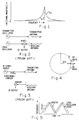
- the misleading logic behind this traditional thinking can be illustrated by the frequency domain display (FIG. 1) of the local oscillator signal, f LO and the returned signal f R of a superheterodyne receiver (FIG. 1).
- the 1/ f noise originates from the deep level traps associated with the surface states of a semiconductor device and this low frequency noise up-converted to the RF frequency by the nonlinear properties inherent in an oscillator shows up as the noise sideband.
- the large surface-to-volume ratio of a FET device structure leads to strong 1/ f noise sidebands near the oscillator frequency.
- the FET oscillator is, therefore, regarded as unsuitable for short-range radar sensor applications based on these noise considerations. This widely accepted concept is correct only under the circumstance where the radar transmitter signal source and the receiver local oscillator power source are uncorrelated.
- FIG. 2 The circuit schematic diagram of such a prior art pulsed radar transceiver is shown in FIG. 2.
- Most long-range ground-based and airborne radars fall into this category because the power levels required for transmitter and receiver operations are significantly different, up to six orders of magnitude in some cases.
- the noise argument presented here is no longer valid once an added constraint is placed between the transmitted and the received signals.
- a single RF signal source serves the dual role of transmitter power source and local oscillator in a FMCW radar transceiver or a Doppler radar sensor shown in FIG. 3.
- a closer examination of the meaning of the frequency domain display in FIG. 1 must be made in order to reevaluate the effect of the added constraint on the performance characteristics of these single signal source radar transceivers.
- the RF signal of an oscillator can be represented by a rotating vector v(t) in FIG. 4.
- the vector is rotating in the counterclockwise direction with an angular frequency or velocity ⁇ .
- the fluctuation in the amplitude of the vector v(t) is the AM noise, while the uncertainty in the angular velocity constitutes the FM noise of the signal source. It is clear from this vectorial representation that the AM noise and the FM noise of an oscillator are orthogonal to each other and that they are uncorrelated.
- ⁇ is defined here as the frequency fluctuation of the RF signal source.
- the short-range radar with a target less than 9,144 m (30 feet) from the transceiver is affected by noise sidebands 4.16 MHz or further away from the average frequency ⁇ o /2 ⁇ .
- This frequency is far higher than the typical IF frequency of the transceiver which is in the kilohertz (KHz) range.
- KHz kilohertz
- the sideband noise is indeed 1/ f in nature, the effect of the oscillator sideband is likely to be at least three orders of magnitude less than what is expected based on the conventional thinking. It is evident that a FET-based monolithic integrated radar is acceptable for short-range radar applications where the target is merely a few feet away.
- Target ranging and velocity can be obtained through the use of a triangular FMWC waveform (FIG. 5) with a predetermined modulation rate.
- the returned signal is displaced in frequency from the instantaneous frequency of the local oscillator drive, as seen in FIG. 5, if a triangular signal is used to modulate the frequency of the oscillator.
- FIG. 6 illustrates a radar transceiver module which has been implemented and tested using all micro-strip technology.
- a combination of localized multi-dose, multi-energy ion implantation, metal/dielectric thin film deposition, fine-line lithography and other techniques for planar microwave integrated circuit manufacturing were employed to fabricate the entire radar transceiver of FIG. 6 on substrates.
- a voltage-controlled (varactor tuned) GaAs FET oscillator 1 is employed as the transceiver power source. It functions both as the transmitter power source and as the local oscillator.
- the oscillator signal may be continuous or pulsed; however, the continuous signal is preferred.
- the oscillator output signal is coupled into a power splitter 3 such as a directional coupler or a hybrid coupler which splits the signal into first and second signal portions, one signal being of sufficient power to drive a mixer and the other signal being the signal to be transmitted.
- the signal to be transmitted is coupled via a circuit 5 to a transmitter antenna 7.
- the second signal is coupled to a Schottky diode 3dB branch line single balanced mixer 9 via a circuit 11.
- This mixer 9 is employed because it has the necessary local oscillator AM noise suppression characteristics and it can be easily implemented in the microstrip configuration.
- a 3dB coupler 8 used in conjunction with the Schottky diode forms a balanced mixer 9 driven by the local oscillator signal at port P1 and the returned signal from port P3 from antennas 12 and 13, which are connected in parallel, by a circuit 15.
- Varactor tuning is the most desirable approach for FMCW radar transceivers because it provides good RF tuning bandwidth and time modulation slew rates.
- the circuit elements described here share the same GaAs monolithic integrated circuit technology, and they are easily integrated onto a common substrate.
- a voltage-controlled (varactor tuned) GaAs FET oscillator 1 has been employed as the transceiver power source despite the conventional belief that the up-converted 1/f noise renders it unsuitable for radar sensor applications.
- a single power source FMCW radar only the noise sideband in the frequency range greater than or equal to the reciprocal of four times the round-trip time delay of the signal is of concern.
- the sensitivity of a radar sensor is dependent on the auto-correlation of the power source with a round-trip signal time delay equal to 2 ⁇ ( ⁇ is the time required for the transmitted signal to reach the target).
- the noise sideband affecting the signal-to-noise ratio of a target at 1 meter from the transceiver antenna is the FM noise of the oscillator 40 MHz away from the instantaneous frequency. Based on this analysis, as discussed hereinbefore, the noise performance of a field effect transistor voltage controlled oscillator will be adequate for a short-range radar sensor.
- the hybrid integrated radar transceiver circuit of FIG. 6 was tested.
- the IF output at terminal 19 was coupled to a signal processor 20.
- Tests were conducted for target range cutoff and indications of increases and decreases in range.
- the 3dB branch line single balanced mixer functioned satisfactorily as an AM noise suppressor, and FM noise did not interfere with range sensing.
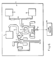
- FIG. 7 illustrates a presently preferred embodiment of this invention.
- This embodiment comprises a microwave transceiver module 21, which is fabricated on a GaAs substrate, and a signal processor module 23, which is separately fabricated.
- the voltage-controlled GaAs FET oscillator 1 has a dual role, functioning as the transmitter signal source and the local oscillator.
- the output of the oscillator 1 is split by means of a power splitter 3, which is coupled to the oscillator by an AM noise suppression amplifier 4.
- One output 5 of the power splitter 3 is coupled to an antenna module 25.
- the second output 11 of the power splitter 3 is coupled to a port P1 of the mixer 9 which, while differently illustrated, is functionally similar to that described in connection with FIG. 6.
- the antenna module 25 comprises a diplexer 27 to which the transmitter signal from the power splitter 3 is coupled.
- the diplexer 27, in turn, is coupled to a single antenna 29.
- the antenna module 25 can be a single antenna 29 fed by a diplexer 27 functioning as a circulator, or two separate antennas (seen in FIG. 6), or a circularly polarized antenna (seen in FIG. 8).
- antenna module 25 comprises a planar integrated antenna such as the conformal dual-feed, circularly polarized microstrip antenna of FIG. 8, a diplexer 27 is not required.
- This antenna operates with a circularly polarized waveform and is suitable for use with the FET-based monolithic radar transceiver.
- the antenna comprises a microstrip branch line coupler 31 functioning as a polarizer, which in this case is a 3dB hybrid coupler, and a dual feed antenna 33, which is a microstrip antenna patch.
- the transmitter signal on circuit 5 is coupled into the left-hand branch of the branch line coupler 31, and the received signal is coupled from the antenna 33 into the right-hand branch of the branch line coupler 31.
- the received or returned signal from the microstrip antenna patch 33 exits the branch line coupler 31 at its right-hand port and is coupled to the port P3 of the mixer 9.
- the RF power from the transmitter power source 1 is divided into two parts which are equal in magnitude and 90° out of phase, by the 3dB branch line coupler 31.
- the antenna 33 is configured as a single element, square-patch resonant microstrip, the circularly polarized radiation of which originates from the excitation of two orthogonal modes on two adjacent edges of the square patch from the outputs of the branch line coupler 31.
- a "fish bone" antenna with radiating elements arranged in the orthogonal directions can be employed.
- the sense of polarization of the returned signal is opposite to that of the transmitted signal upon reflection by a target.
- the polarization function of the branch line coupler 31 recombines the horizontal and vertical components of the returned signal at the mixer input terminal P3.
- the balanced mixer 9 down-converts the return signal to an intermediate frequency (IF) output at terminal 19 for further signal processing.
- IF intermediate frequency
- the signal processing module 23 is used to determine the range and the range rate of targets by analyzing the IF power output of the balanced mixer 9 in the monolithic integrated microwave transceiver module 21.
- the signal processing module comprises a linear amplifier 35 which amplifies the intermediate frequency signal from the mixer 9, an analog-to-digital converter 37, and a digital processor 39 comprising a microprocessor and a fast Fourier transform chip to handle the demodulated signal waveform.
- the varactor drive 2 is synchronized with the digital processor 39.
- a digital range gate 41 receives the output of the digital processor 39.
- the digital range gate 41 is preferred because it provides better range resolution and defines the range of radar sensor operation.
- the signal-processing module 23 also controls the waveform of the radar sensor by providing the timing and the modulation signal to the VCO 1 via the varactor drive 2 in the transceiver. Output of the signal processor 39 is coupled via the range gate 41 to a display unit 43, or in the alternative, to a data storage module (not shown).
- This monolithic FMCW radar sensor is ideal for high-volume, high-rate manufacturing using microwave monolithic circuit technology.
- the up-conversion of the l/f noise normally can be excessive for a field-effect transistor oscillator.
- the 1/f noise is up-converted due to the non-linear characteristics of the oscillator. It becomes the sideband noise close to the oscillator frequency f0. If such an oscillator 1 is used as a local oscillator in a mixer down-converter in a system employing a separate transmitter power oscillator, the sideband noise shows up as the IF noise corresponding to the difference between the instantaneous frequency f0 of the local oscillator and the frequency of the returned signal. This high noise background of the IF output causes undesirable degradation of the receiver signal-to-noise ratio and sensitivity.
- a FMCW radar sensor employs a single oscillator 1 to serve as the transmitter power source as well as the receiver local oscillator.
- the noise output of the mixer intermediate frequency is a measure of the uncertainty of the correlation of the oscillator with a round-trip time delay 2 ⁇ , where 2 ⁇ is the round-trip time of the signal to and from the target.
- the noise sideband of the oscillator at frequencies approximately 1/8 ⁇ is the only factor affecting the signal-to-noise ratio of the FMCW radar transceiver, and the up-converted 1/f noise is not a significant factor in system performance.
- ⁇ is small, that is less than 1000 nanoseconds (corresponding to 152,4 m (500 foot) target range), the sideband noise at 250 KHz or further away will affect the system operation, while the low frequency noise (250 KHz from the carrier) will have no degradation effect.
- Hyper-abrupt pn junction varactor diodes fabricated using high energy localized implantation and rapid thermal annealing techniques are compatible with FET based monolithic integrated circuits.
- Varactor tuning is the most desirable approach for FMCW radars because it provides good RF tuning bandwidth at high modulation slew rates.
- the 1/ f noise up-conversion by the nonlinear characteristics inherent in a FET oscillator is not detrimental to radar transceiver function at short ranges.
- only the noise sideband in the frequency range equal to the reciprocal of four times the round-trip time delay is of concern.
- the sensitivity of such a radar sensor is only dependent on the auto correlation of the power source with a time delay equal to 2 ⁇ .
- the noise sideband affecting the signal-to-noise ratio of a target at 0,6096 m (2 feet) from the transceiver is the FM noise of the oscillator 62.5 MHz away from the instantaneous frequency.
- the 3dB quadrature hybrid coupler 31 is adopted for use as the polarizer in this circularly polarized FMCW system. It has sufficient bandwidth and it is relatively simple to design and fabricate with high-yield.
- Planar microstrip antennas such as the antenna 33, FIG. 8, are lightweight, economical and easily adaptable to inter-connect with the integrated RF transceiver module. Microstrip patch antennas 33 can be batch-fabricated using conventional printed circuit techniques, leading to a reduction in manufacturing cost compared to the commonly used horn antenna.
- the Schottky diode single balanced mixer 9 using a lumped-element 3dB coupler 8 (FIGS. 6 and 7) is employed in this system because it has the necessary local oscillator AM noise suppression characteristics and is capable of meeting all the operational requirements of the transceiver.
- the lumped-element design enables minimization of the size of the integrated circuit.
- a dc voltage is developed at the output 19 of the balanced mixer 9 (FIGS. 6 and 7) if the transmitted signal is reflected by an object placed right in front of the antenna. This property can be utilized to detect obstacles at close range or the condition of an obscured antenna caused by environmental conditions such as ice or mud covering.
- the branch line single balanced mixer 9 is simple to fabricate in the microstrip configuration and lends itself well to planar monolithic integration.
- Field effect transistor oscillators do not possess the inherent negative resistance properties, as do many of the two-terminal devices.
- the negative resistance required to cause oscillations in a field effect transistor oscillator has to be simulated by applying suitable feedback from the output to the input of the device.
- the field effect transistor oscillator is designed for implementation in monolithic technology. Its basic circuit configuration, which includes a commongate GaAs FET and a varactor diode C v , is shown in FIG. 9. Capacitors C1 and C2, which are often actually internal device capacitances, form a feedback network, feeding a fraction of the output voltage into the input port. Since the output voltage is essentially in phase with the input voltage, the feedback is positive and a negative resistance (-R f ) develops between the drain and the gate terminals, D and G, of the FET.
- a FMCW radar transceiver system as described herein, with a range gate limiting the range of operation will, therefore, be able to take advantage of the low-cost FET-based monolithic integrated circuit technology.
- the 1 f noise is not a problem.
- the AM noise is easily suppressed, as described above, using a balanced mixer 9 or a saturation amplifier stage 4 following the oscillator, or both.
Abstract
Description
- This invention relates to radar, and more particularly to radar transceivers for short-range target detection.
- Frequency modulated continuous wave (FMCW) radar systems using solid state components are commonly found in short-range radar detection applications. Prior art FMCW radar transceivers have been based on microwave power sources such as a vacuum tube, typically a klystron, or a transferred electron device such as a Gunn diode. These conventional approaches do not lend themselves to monolithic circuit fabrication techniques which are ideal for high production implementation.
- In U.S. patent 4,742,354, to Cheng P. Wen, et al., assigned to the assignee of this invention, the present applicant describes a radar transceiver employing a transmitter oscillator, a directional coupler for splitting the oscillator signal into two signals in quadrature phase relationship, and a single antenna for radiating the signals as a circularly polarized waveform. Portions of the circularly polarized waveform that are reflected back are received by the same antenna. The directional coupler combines the two components of the circularly polarized wave into a signal which is down-converted into a signal of intermediate frequency by a mixer. The radar transceiver is hybrid integrated and is fabricated on a single substrate such as a Duroid substrate (Duroid is a registered trademark of Rogers Corporation). A voltage controlled Gunn oscillator is suggested as the transmitter oscillator which, as noted above, does not lend itself to monolithic circuit fabrication techniques. Specific fabrication techniques are not described with respect to the oscillator.
- Background art described in this patent includes:
- (1) radar transceivers having separate transmitter and receiver antennas;
- (2) those having a single antenna in which the transmitted and returned signals are directed through a circulator; and
- (3) those having a single antenna employing a 3-dB coupler for signal coupling at the antenna.
- In fact, in a paper entitled "Solid State Local Oscillator Sources for Millimeter and Sub-Millimeter Wave Applications", by Terrial Cutsinger, presented at the 12th International Conference on Infrared and Millimeter Waves, December 14-18, 1987, Orlando, Florida, it was stated:
"Solid state devices such as FET's and IMPATT diodes are capable of generating power at millimeter-wave frequencies. Both of these however, have inherent problems which limit their usefulness. FET oscillators provide relatively low power and produce high 1/F noise. Additionally, they are limited to the lower millimeter-wave frequencies, but IMPATTS exhibit high AM noise which degrades system noise performance." - In this paper, Gunn device oscillators were stated to provide a reliable solution to the problems inherent to FET and IMPATT oscillators, pointing to their sufficiency of RF power, low AM and FM noise, and the ability to drive a mixer up to 110 GHz without frequency multiplication.
- Document IEEE MTT International Microwave Symposium DIGEST; 25-27 May 1988, vol. 1, pp 99-101 relates to a GaAs monolithic circuit for FMCW radar systems. The circuit comprises a field effect transistor oscillator means for generating a time varying signal, antenna means for transmitting signals to a target and for receiving signals reflected from the target, means for coupling the time varying signal to the antenna means, a mixer having a first port for receiving the time varying signal and a second port for receiving signals from the antenna means for producing an intermediate frequency signal, and signal processing means responsive to the intermediate frequency signal for producing indications of the range and/or the rate of change of the range of the target. This system is provided for operation at longer ranges.
- Document IEEE MTT International Microwave Symposium DIGEST; 1981, pp 319-321 is concerned with a MIC direction sensitive Doppler module with GaAs FET oscillator which is stabilized by a dielectric resonator. However, this document includes no hint to a utilization of the GaAs FET oscillator in a short-range radar transceiver.
- From document EP-A-0 156 708 the design of a microwave FET oscillator as common gate oscillator is known. The oscillator comprises a variable capacitor controlled by an applied voltage. This document, too, does not comprise any information about the use of a FET oscillator in a short-range radar transceiver.
- It is an object of the invention to shorten the range of a radar transceiver.
- The technical problem is solved by an apparatus in accordance with
claim 1. - This invention provides a FET oscillator-based FMCW radar transceiver which is ideally suited for short-range target detection applications. The radar transceiver comprises a FET voltage controlled oscillator and a balanced mixer. One embodiment employs separate microstrip transmitting and receiving antennas, and a second embodiment employs a circulatorless, circularly polarized microstrip integrated antenna. A digital signal processor with a range gate receives a digitized IF signal and is employed to identify the targets and the target velocities. As noted above, the FET oscillator was considered unsuitable for short-range radar applications because of the excessive up-converted 1/f noise. The self-correlation nature of this FMCW radar transceiver combined with the AM noise suppression of the balanced mixer enables the fabrication of a low-cost radar sensor using well-established monolithic integrated circuit technology.
- This solid state FMCW radar transceiver for short-range applications provides improvements over prior art arrangements for such applications because it offers the advantages of durability, small size, lightweight, and is adaptable to low-cost manufacturing while still providing or retaining the ability to penetrate fog, dust, and smoke.
- The radar transceiver system is a simple motion detector if the transmitter frequency remains constant. In a preferred embodiment, the radio frequency (RF) transmitter power and the local oscillator (LO) drive for the mixer stage are provided by a common voltage controlled oscillator (VCO) which is a FET oscillator. This microwave integrated circuit FMCW radar transceiver operates with a circularly polarized waveform. Such a waveform is particularly attractive for automotive "rearview mirror" and short-range collision avoidance applications because the antenna required uses directional couplers in place of non-reciprocal elements such as circulators, which are required in conventional radars.
- The invention will be better understood by reference to the following descriptive disclosure when considered in conjunction with the accompanying drawings, in which:
- FIG. 1 is a frequency domain display of a local oscillator signal;
- FIG. 2 is a schematic representation of a prior art pulsed radar transceiver;
- FIG. 3 schematically depicts a FMCW radar transceiver having a single RF signal source;
- FIG. 4 is a diagram depicting a rotating vector showing the phase relationship of AM and FM noise;
- FIG. 5 depicts transmitted and received triangular FMCW waveforms and their frequency difference in time;
- FIG. 6 is a drawing to an enlarged scale of the planform of a hybrid integrated short-range radar transceiver circuit which has been constructed and tested, employing a FET oscillator, and which embodies the principals of this invention;
- FIG. 7 is a block diagram of a presently preferred embodiment of this invention;
- FIG. 8 schematically depicts a conformal dualfeed circularly polarized microstrip antenna; and
- FIG. 9 schematically illustrates a presently preferred GaAs FET VCO.
- The FET based microwave monolithic integrated circuit is ideally suited for short-range applications where durability, low cost, compact size, light weight, and high volume production are essential. However, in spite of these advantages, this promising technology has not been incorporated into radar sensor designs because the FET oscillator was considered to be too noisy for any radar application. We have determined that the noise characteristics of a FET oscillator will not cause serious performance degradation if a single RF signal source is used in a short-range radar transceiver. Consequently, the FET based monolithic integrated radar transceiver is ideal for use in short-range applications.
- The Gunn diode (transferred electron device) oscillator is traditionally used in radar sensor applications because of its "spectral purity." The misleading logic behind this traditional thinking can be illustrated by the frequency domain display (FIG. 1) of the local oscillator signal, f LO and the returned signal f R of a superheterodyne receiver (FIG. 1). The intermediate frequency (f IF = f LO - f R) of a typical short-range FMCW or Doppler radar is so small that the returned signal appears to be obscured by the 1/f noise sideband of the local oscillator. The 1/f noise originates from the deep level traps associated with the surface states of a semiconductor device and this low frequency noise up-converted to the RF frequency by the nonlinear properties inherent in an oscillator shows up as the noise sideband. The large surface-to-volume ratio of a FET device structure leads to strong 1/f noise sidebands near the oscillator frequency. The FET oscillator is, therefore, regarded as unsuitable for short-range radar sensor applications based on these noise considerations. This widely accepted concept is correct only under the circumstance where the radar transmitter signal source and the receiver local oscillator power source are uncorrelated.
- The circuit schematic diagram of such a prior art pulsed radar transceiver is shown in FIG. 2. Most long-range ground-based and airborne radars fall into this category because the power levels required for transmitter and receiver operations are significantly different, up to six orders of magnitude in some cases. The noise argument presented here is no longer valid once an added constraint is placed between the transmitted and the received signals. For instance, a single RF signal source serves the dual role of transmitter power source and local oscillator in a FMCW radar transceiver or a Doppler radar sensor shown in FIG. 3. A closer examination of the meaning of the frequency domain display in FIG. 1 must be made in order to reevaluate the effect of the added constraint on the performance characteristics of these single signal source radar transceivers.
- The RF signal of an oscillator can be represented by a rotating vector v(t) in FIG. 4. The vector is rotating in the counterclockwise direction with an angular frequency or velocity ω. The fluctuation in the amplitude of the vector v(t) is the AM noise, while the uncertainty in the angular velocity constitutes the FM noise of the signal source. It is clear from this vectorial representation that the AM noise and the FM noise of an oscillator are orthogonal to each other and that they are uncorrelated.
- It is important to understand how the noise sideband of an oscillator affects the performance of a radar with a single RF signal source. For instance, the IF output of a balanced mixer in such a radar transceiver is approximately

if the signal source is v(t) = cos (ωo + δω)t and the round-trip time of the returned signal is 2τ. δω is defined here as the frequency fluctuation of the RF signal source. The IF signal drops to zero when 2δωτ approaches π/2; i.e., 2 δω = π/4I for the performance of the transceiver to be seriously affected. The short-range radar with a target less than 9,144 m (30 feet) from the transceiver is affected by noise sidebands 4.16 MHz or further away from the average frequency ωo/2π . This frequency is far higher than the typical IF frequency of the transceiver which is in the kilohertz (KHz) range. If the sideband noise is indeed 1/f in nature, the effect of the oscillator sideband is likely to be at least three orders of magnitude less than what is expected based on the conventional thinking. It is evident that a FET-based monolithic integrated radar is acceptable for short-range radar applications where the target is merely a few feet away. - Target ranging and velocity can be obtained through the use of a triangular FMWC waveform (FIG. 5) with a predetermined modulation rate. The returned signal is displaced in frequency from the instantaneous frequency of the local oscillator drive, as seen in FIG. 5, if a triangular signal is used to modulate the frequency of the oscillator.
- FIG. 6 illustrates a radar transceiver module which has been implemented and tested using all micro-strip technology. A combination of localized multi-dose, multi-energy ion implantation, metal/dielectric thin film deposition, fine-line lithography and other techniques for planar microwave integrated circuit manufacturing were employed to fabricate the entire radar transceiver of FIG. 6 on substrates. In FIG. 6, a voltage-controlled (varactor tuned)
GaAs FET oscillator 1 is employed as the transceiver power source. It functions both as the transmitter power source and as the local oscillator. The oscillator signal may be continuous or pulsed; however, the continuous signal is preferred. The oscillator output signal is coupled into apower splitter 3 such as a directional coupler or a hybrid coupler which splits the signal into first and second signal portions, one signal being of sufficient power to drive a mixer and the other signal being the signal to be transmitted. - The signal to be transmitted, say the first signal, is coupled via a
circuit 5 to atransmitter antenna 7. The second signal is coupled to a Schottky diode 3dB branch line singlebalanced mixer 9 via a circuit 11. Thismixer 9 is employed because it has the necessary local oscillator AM noise suppression characteristics and it can be easily implemented in the microstrip configuration. A 3dB coupler 8 used in conjunction with the Schottky diode forms abalanced mixer 9 driven by the local oscillator signal at port P1 and the returned signal from port P3 fromantennas circuit 15. Varactor tuning is the most desirable approach for FMCW radar transceivers because it provides good RF tuning bandwidth and time modulation slew rates. The circuit elements described here share the same GaAs monolithic integrated circuit technology, and they are easily integrated onto a common substrate. - In this implementation, a voltage-controlled (varactor tuned)
GaAs FET oscillator 1 has been employed as the transceiver power source despite the conventional belief that the up-converted 1/f noise renders it unsuitable for radar sensor applications. In a single power source FMCW radar, only the noise sideband in the frequency range greater than or equal to the reciprocal of four times the round-trip time delay of the signal is of concern. The sensitivity of a radar sensor is dependent on the auto-correlation of the power source with a round-trip signal time delay equal to 2τ (τ is the time required for the transmitted signal to reach the target). For instance, the noise sideband affecting the signal-to-noise ratio of a target at 1 meter from the transceiver antenna is the FM noise of the oscillator 40 MHz away from the instantaneous frequency. Based on this analysis, as discussed hereinbefore, the noise performance of a field effect transistor voltage controlled oscillator will be adequate for a short-range radar sensor. - The hybrid integrated radar transceiver circuit of FIG. 6 was tested. The IF output at terminal 19 was coupled to a
signal processor 20. Tests were conducted for target range cutoff and indications of increases and decreases in range. The 3dB branch line single balanced mixer functioned satisfactorily as an AM noise suppressor, and FM noise did not interfere with range sensing. - FIG. 7 illustrates a presently preferred embodiment of this invention. This embodiment comprises a
microwave transceiver module 21, which is fabricated on a GaAs substrate, and asignal processor module 23, which is separately fabricated. Here again, the voltage-controlledGaAs FET oscillator 1 has a dual role, functioning as the transmitter signal source and the local oscillator. Again, the output of theoscillator 1 is split by means of apower splitter 3, which is coupled to the oscillator by an AM noise suppression amplifier 4. Oneoutput 5 of thepower splitter 3 is coupled to anantenna module 25. The second output 11 of thepower splitter 3 is coupled to a port P1 of themixer 9 which, while differently illustrated, is functionally similar to that described in connection with FIG. 6. Theantenna module 25 comprises adiplexer 27 to which the transmitter signal from thepower splitter 3 is coupled. Thediplexer 27, in turn, is coupled to asingle antenna 29. Theantenna module 25 can be asingle antenna 29 fed by adiplexer 27 functioning as a circulator, or two separate antennas (seen in FIG. 6), or a circularly polarized antenna (seen in FIG. 8). - When
antenna module 25 comprises a planar integrated antenna such as the conformal dual-feed, circularly polarized microstrip antenna of FIG. 8, adiplexer 27 is not required. This antenna operates with a circularly polarized waveform and is suitable for use with the FET-based monolithic radar transceiver. The antenna comprises a microstrip branch line coupler 31 functioning as a polarizer, which in this case is a 3dB hybrid coupler, and adual feed antenna 33, which is a microstrip antenna patch. The transmitter signal oncircuit 5 is coupled into the left-hand branch of the branch line coupler 31, and the received signal is coupled from theantenna 33 into the right-hand branch of the branch line coupler 31. The received or returned signal from themicrostrip antenna patch 33 exits the branch line coupler 31 at its right-hand port and is coupled to the port P3 of themixer 9. - In this application, the RF power from the
transmitter power source 1 is divided into two parts which are equal in magnitude and 90° out of phase, by the 3dB branch line coupler 31. Theantenna 33 is configured as a single element, square-patch resonant microstrip, the circularly polarized radiation of which originates from the excitation of two orthogonal modes on two adjacent edges of the square patch from the outputs of the branch line coupler 31. Alternatively, a "fish bone" antenna with radiating elements arranged in the orthogonal directions can be employed. The sense of polarization of the returned signal is opposite to that of the transmitted signal upon reflection by a target. The polarization function of the branch line coupler 31 recombines the horizontal and vertical components of the returned signal at the mixer input terminal P3. Little or no return signal should go back toward the VCO1 because of phase cancellation provided by the polarization function of the coupler 31. Similarly, the polarization function minimizes the possibility of any direct RF signal from a similar radar system from reaching the sensitive receiverbalanced mixer 9. Thebalanced mixer 9 down-converts the return signal to an intermediate frequency (IF) output at terminal 19 for further signal processing. - The
signal processing module 23 is used to determine the range and the range rate of targets by analyzing the IF power output of thebalanced mixer 9 in the monolithic integratedmicrowave transceiver module 21. The signal processing module comprises alinear amplifier 35 which amplifies the intermediate frequency signal from themixer 9, an analog-to-digital converter 37, and adigital processor 39 comprising a microprocessor and a fast Fourier transform chip to handle the demodulated signal waveform. A varactor drive 2, referred to in the discussion with respect to FIG. 6, forms part of thesignal processor module 23, in this illustration. Its output is connected to the voltage-controlledoscillator 1 and provides frequency tuning of the oscillator. The varactor drive 2 is synchronized with thedigital processor 39. Adigital range gate 41 receives the output of thedigital processor 39. Thedigital range gate 41 is preferred because it provides better range resolution and defines the range of radar sensor operation. The signal-processingmodule 23 also controls the waveform of the radar sensor by providing the timing and the modulation signal to theVCO 1 via the varactor drive 2 in the transceiver. Output of thesignal processor 39 is coupled via therange gate 41 to adisplay unit 43, or in the alternative, to a data storage module (not shown). This monolithic FMCW radar sensor is ideal for high-volume, high-rate manufacturing using microwave monolithic circuit technology. - The up-conversion of the l/f noise normally can be excessive for a field-effect transistor oscillator. The 1/f noise is up-converted due to the non-linear characteristics of the oscillator. It becomes the sideband noise close to the oscillator frequency f₀. If such an
oscillator 1 is used as a local oscillator in a mixer down-converter in a system employing a separate transmitter power oscillator, the sideband noise shows up as the IF noise corresponding to the difference between the instantaneous frequency f₀ of the local oscillator and the frequency of the returned signal. This high noise background of the IF output causes undesirable degradation of the receiver signal-to-noise ratio and sensitivity. - However, a FMCW radar sensor according to this invention employs a
single oscillator 1 to serve as the transmitter power source as well as the receiver local oscillator. In such a single oscillator source system, the noise output of the mixer intermediate frequency is a measure of the uncertainty of the correlation of the oscillator with a round-trip time delay 2τ, where 2 τ is the round-trip time of the signal to and from the target. The noise sideband of the oscillator at frequencies approximately 1/8τ is the only factor affecting the signal-to-noise ratio of the FMCW radar transceiver, and the up-converted 1/f noise is not a significant factor in system performance. If τ is small, that is less than 1000 nanoseconds (corresponding to 152,4 m (500 foot) target range), the sideband noise at 250 KHz or further away will affect the system operation, while the low frequency noise (250 KHz from the carrier) will have no degradation effect. - Hyper-abrupt pn junction varactor diodes fabricated using high energy localized implantation and rapid thermal annealing techniques are compatible with FET based monolithic integrated circuits. Varactor tuning is the most desirable approach for FMCW radars because it provides good RF tuning bandwidth at high modulation slew rates. The 1/f noise up-conversion by the nonlinear characteristics inherent in a FET oscillator is not detrimental to radar transceiver function at short ranges. In the case of a single power source FMCW radar or a motion detector for use as a short range sensor, only the noise sideband in the frequency range equal to the reciprocal of four times the round-trip time delay is of concern. The sensitivity of such a radar sensor is only dependent on the auto correlation of the power source with a time delay equal to 2τ. The noise sideband affecting the signal-to-noise ratio of a target at 0,6096 m (2 feet) from the transceiver is the FM noise of the oscillator 62.5 MHz away from the instantaneous frequency.
- Based on the foregoing analysis, the noise performance of a FET VCO will be adequate for short-range applications if the AM noise from the LO is suppressed. The 3dB quadrature hybrid coupler 31 is adopted for use as the polarizer in this circularly polarized FMCW system. It has sufficient bandwidth and it is relatively simple to design and fabricate with high-yield. Planar microstrip antennas such as the
antenna 33, FIG. 8, are lightweight, economical and easily adaptable to inter-connect with the integrated RF transceiver module.Microstrip patch antennas 33 can be batch-fabricated using conventional printed circuit techniques, leading to a reduction in manufacturing cost compared to the commonly used horn antenna. The Schottky diode singlebalanced mixer 9 using a lumped-element 3dB coupler 8 (FIGS. 6 and 7) is employed in this system because it has the necessary local oscillator AM noise suppression characteristics and is capable of meeting all the operational requirements of the transceiver. The lumped-element design enables minimization of the size of the integrated circuit. In addition, a dc voltage is developed at the output 19 of the balanced mixer 9 (FIGS. 6 and 7) if the transmitted signal is reflected by an object placed right in front of the antenna. This property can be utilized to detect obstacles at close range or the condition of an obscured antenna caused by environmental conditions such as ice or mud covering. The branch line singlebalanced mixer 9 is simple to fabricate in the microstrip configuration and lends itself well to planar monolithic integration. - Field effect transistor oscillators do not possess the inherent negative resistance properties, as do many of the two-terminal devices. The negative resistance required to cause oscillations in a field effect transistor oscillator has to be simulated by applying suitable feedback from the output to the input of the device.
- The most attractive approach for a broadband oscillator is the field effect transistor oscillator operating in common gate configuration. This configuration is attractive because the inherent broadband positive feedback produced by the built-in capacitance between drain and source of the transistor is ideally suitable for tunable oscillator application.
- The field effect transistor oscillator is designed for implementation in monolithic technology. Its basic circuit configuration, which includes a commongate GaAs FET and a varactor diode Cv, is shown in FIG. 9. Capacitors C₁ and C₂, which are often actually internal device capacitances, form a feedback network, feeding a fraction of the output voltage into the input port. Since the output voltage is essentially in phase with the input voltage, the feedback is positive and a negative resistance (-Rf) develops between the drain and the gate terminals, D and G, of the FET. If the feedback resistance Rf is greater than the load resistance RL, oscillations build up in the circuit formed by the field effect transistor, inductance L (L₁, L₂), capacitance C (C₁, C₂, CS, CV) and the output resistance load RL. Equilibrium is achieved when, with the onset of saturation, Rf decreases to a value equal to RL, and the total circuit resistance becomes zero. The frequency of oscillation is set by the resonant frequency of the circuit LC Loop with the FET acting as the active source sustaining the loop current.
- A FMCW radar transceiver system, as described herein, with a range gate limiting the range of operation will, therefore, be able to take advantage of the low-cost FET-based monolithic integrated circuit technology. The 1f noise is not a problem. The AM noise is easily suppressed, as described above, using a
balanced mixer 9 or a saturation amplifier stage 4 following the oscillator, or both.
All such systems, as presently known, typically include conventional oscillators such as a klystron or a Gunn oscillator. A FET oscillator such as a GaAs FET oscillator is not employed.
Claims (12)
- A short-range radar transceiver comprising:
oscillator means (1) for generating a time varying signal, said oscillator means (1) being formed by a field effect transistor oscillator means;
antenna means (7, 12, 13; 25, 29) for transmitting signals to a target and for receiving signals reflected from said target;
means (3, 5) for coupling said time varying signal to said antenna means (7; 25, 29) to be transmitted therefrom;
a mixer (9) having a first port for receiving said time varying signal and a second port for receiving signals from said antenna means for producing an intermediate frequency signal; and
signal processing means (20; 23) responsive to said intermediate frequency signal for producing indications of the range and/or the rate of change of said range of said target,
said radar transceiver being characterised by further comprising
a range gate (20; 23) responsive to said intermediate frequency signal and adapted to limit the range of operation of said radar transceiver to less than about 152,4 m (500 feet) so that the sideband noise due to the oscillator means (1) does not obscure the intermediate frequency signal. - The radar transceiver according to Claim 1, in which:
said field effect transistor oscillator means (1) comprises a varactor diode (Cv) for tuning said oscillator means (1). - The radar transceiver according to Claim 1, in which:
said time varying signal of said field effect transistor oscillator means (1) is a constant frequency oscillating signal. - The radar transceiver according to Claim 1, in which:
said mixer (9) is a balanced mixer for suppressing AM noise. - The radar transceiver according to Claim 1, in which:
said field effect transistor oscillator means (1) comprises a common gate field effect transistor circuit. - The radar transceiver according to Claim 5, in which:
said common gate field effect transistor circuit is a monolithic structure on a single crystal semiconductor substrate. - The radar transceiver according to Claim 6, in which:
said common gate field effect transistor circuit comprises a gallium arsenide field effect transistor. - The radar transceiver according to Claim 1, in which:
said time varying signal is a frequency modulated continuous triangular waveform signal. - The radar transceiver according to Claim 1, in which:
said antenna means (7, 12, 13; 25, 29) comprises a transmitter antenna (7) and a receiver antenna (12, 13) said transmitter antenna (7) receiving said time varying signal and said receiver antenna (12, 13) being coupled to said second port of said mixer (9) for coupling a received signal to said mixer (9). - The radar transceiver according to Claim 9, in which:
said transmitter antenna (7) and said receiver antenna (12, 13) are microstrip antennas on a substrate. - The radar transceiver according to Claim 1, in which:
said means (3, 5) for coupling said time varying signal to said antenna means comprises a power splitter (3) for splitting said time varying signal into first and second signals for said antenna means (7; 25, 29) and said mixer (9). - The radar transceiver according to Claim 1, in which:
said range is less than about 9,144 m (30 feet).
Applications Claiming Priority (3)
| Application Number | Priority Date | Filing Date | Title |
|---|---|---|---|
| US342850 | 1989-04-24 | ||
| US07/342,850 US4931799A (en) | 1989-04-24 | 1989-04-24 | Short-range radar transceiver employing a FET oscillator |
| PCT/US1990/001546 WO1990013049A1 (en) | 1989-04-24 | 1990-03-23 | Short-range radar transceiver employing a fet oscillator |
Publications (2)
| Publication Number | Publication Date |
|---|---|
| EP0424509A1 EP0424509A1 (en) | 1991-05-02 |
| EP0424509B1 true EP0424509B1 (en) | 1994-12-07 |
Family
ID=23343538
Family Applications (1)
| Application Number | Title | Priority Date | Filing Date |
|---|---|---|---|
| EP90907667A Expired - Lifetime EP0424509B1 (en) | 1989-04-24 | 1990-03-23 | Short-range radar transceiver employing a fet oscillator |
Country Status (7)
| Country | Link |
|---|---|
| US (1) | US4931799A (en) |
| EP (1) | EP0424509B1 (en) |
| JP (1) | JPH03505636A (en) |
| KR (1) | KR940005963B1 (en) |
| CA (1) | CA2028860C (en) |
| DE (1) | DE69014828T2 (en) |
| WO (1) | WO1990013049A1 (en) |
Cited By (1)
| Publication number | Priority date | Publication date | Assignee | Title |
|---|---|---|---|---|
| DE10156258A1 (en) * | 2001-11-09 | 2003-05-28 | Bosch Gmbh Robert | Integrated semiconductor device for high-frequency measurements and its use |
Families Citing this family (40)
| Publication number | Priority date | Publication date | Assignee | Title |
|---|---|---|---|---|
| US5036327A (en) * | 1990-07-19 | 1991-07-30 | Honeywell Inc. | Single oscillator FSK pulsed radar receiving transmitter |
| US5115245A (en) * | 1990-09-04 | 1992-05-19 | Hughes Aircraft Company | Single substrate microwave radar transceiver including flip-chip integrated circuits |
| JP2583723B2 (en) * | 1991-04-18 | 1997-02-19 | エンドレス ウント ハウザー ゲゼルシヤフト ミツト ベシユレンクテル ハフツング ウント コンパニー | Method and apparatus for distance measurement by reflected beam method |
| US5159346A (en) * | 1991-06-10 | 1992-10-27 | Alliant Techsystems Inc. | Voltage controlled oscillator |
| US5512901A (en) * | 1991-09-30 | 1996-04-30 | Trw Inc. | Built-in radiation structure for a millimeter wave radar sensor |
| US5315303A (en) * | 1991-09-30 | 1994-05-24 | Trw Inc. | Compact, flexible and integrated millimeter wave radar sensor |
| US5263198A (en) * | 1991-11-05 | 1993-11-16 | Honeywell Inc. | Resonant loop resistive FET mixer |
| ATE180575T1 (en) * | 1993-08-09 | 1999-06-15 | Siemens Ag | DOUBLE RADAR MODULE USING MICRO STRIP LINE TECHNOLOGY |
| US5512911A (en) * | 1994-05-09 | 1996-04-30 | Disys Corporation | Microwave integrated tuned detector |
| GB9504259D0 (en) * | 1995-03-03 | 1995-04-19 | Marconi Gec Ltd | Integrated microwave circuit board for millimetric wavelengths |
| US5852771A (en) * | 1996-06-14 | 1998-12-22 | The Whitaker Corporation | Mixer with two diodes including DC coupled if |
| US5914683A (en) * | 1996-09-12 | 1999-06-22 | O'conner; Joe S. | Ultra high resolution ranging unit |
| US5933108A (en) * | 1997-04-16 | 1999-08-03 | Itt Manufacturing Enterprises, Inc. | Gallium arsenide-based vector controller for microwave circuits |
| US7324039B2 (en) * | 2004-12-16 | 2008-01-29 | Automotive Technologies International, Inc. | Short-range automotive radar transceiver |
| US5929802A (en) * | 1997-11-21 | 1999-07-27 | Raytheon Company | Automotive forward looking sensor application |
| DE69813005T2 (en) * | 1997-11-21 | 2004-01-29 | Raytheon Co | FORWARD VISION SENSOR FOR MOTOR VEHICLES |
| US6049702A (en) * | 1997-12-04 | 2000-04-11 | Rockwell Science Center, Llc | Integrated passive transceiver section |
| US6043774A (en) * | 1998-03-25 | 2000-03-28 | Honeywell Inc. | Near-range proximity sensor having a fast-tracking analog |
| US6438365B1 (en) * | 1998-06-02 | 2002-08-20 | Philsar Semiconductor Inc. | Balanced mixer with feedback pre-amplifier |
| US6091355A (en) * | 1998-07-21 | 2000-07-18 | Speed Products, Inc. | Doppler radar speed measuring unit |
| US6529712B1 (en) * | 1999-08-25 | 2003-03-04 | Conexant Systems, Inc. | System and method for amplifying a cellular radio signal |
| SG90071A1 (en) * | 1999-10-01 | 2002-07-23 | Agilis Comm Technologies Pte L | Motion detector |
| KR20030030400A (en) * | 2001-10-10 | 2003-04-18 | (주)마이크로라인 | Radar-Detector using transistor mixer |
| DE10238711A1 (en) * | 2002-08-23 | 2004-03-04 | Valeo Schalter Und Sensoren Gmbh | Method and device for generating and discontinuously transmitting a fundamental wave in a predetermined carrier frequency |
| DE10300955B4 (en) * | 2003-01-13 | 2005-10-27 | Epcos Ag | Radar transceiver for microwave and millimeter wave applications |
| KR100713155B1 (en) * | 2005-07-13 | 2007-05-02 | 삼성전자주식회사 | Radar system comprising single circularly polarized antenna |
| US7573420B2 (en) * | 2007-05-14 | 2009-08-11 | Infineon Technologies Ag | RF front-end for a radar system |
| US7782251B2 (en) * | 2007-10-06 | 2010-08-24 | Trex Enterprises Corp. | Mobile millimeter wave imaging radar system |
| US20100042350A1 (en) * | 2008-08-12 | 2010-02-18 | Certrite Llc | Doppler radar gun certification system |
| TWI430902B (en) * | 2010-12-15 | 2014-03-21 | Wistron Neweb Corp | Wireless signal transceiver and blind spot detection system |
| RU2475771C1 (en) * | 2011-10-27 | 2013-02-20 | Федеральное государственное бюджетное образовательное учреждение высшего профессионального образования "Национальный исследовательский университет "МИЭТ" (МИЭТ) | Device to detect moving object |
| TWI482361B (en) * | 2012-01-18 | 2015-04-21 | Cirocomm Technology Corp | Automatic testing and trimming method for planar antenna and system for the same |
| CN203434265U (en) * | 2013-04-19 | 2014-02-12 | 深圳市海骏电子科技有限公司 | Planar antenna microwave module and intelligent control energy-saving lamp |
| US9400322B2 (en) * | 2013-11-12 | 2016-07-26 | Raytheon Company | Methods and apparatus for signal sideband receiver/transceiver for phased array radar antenna |
| US9389113B2 (en) | 2014-03-05 | 2016-07-12 | Rosemount Tank Radar Ab | Low power radar level gauge system |
| US9395229B2 (en) | 2014-03-05 | 2016-07-19 | Rosemount Tank Radar Ab | Low power radar level gauge system with integrated microwave circuit |
| CN103913742B (en) * | 2014-04-25 | 2016-01-13 | 桂林电子科技大学 | The automobile anti-collision radar system of double reception antenna and operation method |
| CN105866746A (en) * | 2016-04-01 | 2016-08-17 | 芜湖航飞科技股份有限公司 | Application of FMCW system T/R unit in digital phased array |
| GB2569827B (en) * | 2018-01-02 | 2022-03-30 | S&Ao Ltd | A radar device |
| DE102018200647A1 (en) * | 2018-01-16 | 2019-07-18 | Vega Grieshaber Kg | RADAR TRANSCEIVER CHIP |
Family Cites Families (11)
| Publication number | Priority date | Publication date | Assignee | Title |
|---|---|---|---|---|
| US2927319A (en) * | 1957-01-16 | 1960-03-01 | Philco Corp | Short range radar system |
| JPS54111799A (en) * | 1978-02-21 | 1979-09-01 | Mitsubishi Electric Corp | Doppler radar unit |
| US4255730A (en) * | 1978-10-24 | 1981-03-10 | Hitachi, Ltd. | Microwave integrated circuit device |
| US4541120A (en) * | 1982-08-19 | 1985-09-10 | International Standard Electric Corporation | Transmitter-receiver module |
| FR2541465B1 (en) * | 1983-02-18 | 1985-10-11 | Thomson Csf | FREQUENCY MODULATED CONTINUOUS WAVE RADAR AND ITS APPLICATION TO AN ALTIMETRIC PROBE |
| US4736454A (en) * | 1983-09-15 | 1988-04-05 | Ball Corporation | Integrated oscillator and microstrip antenna system |
| FR2561048B1 (en) * | 1984-03-09 | 1986-09-19 | Thomson Csf | TRANSISTOR MICROWAVE OSCILLATOR, VARIABLE CAPACITY CONTROL |
| GB2181007A (en) * | 1985-09-27 | 1987-04-08 | Philips Electronic Associated | Distributed amplifier load arrangements |
| FR2589294B1 (en) * | 1985-10-29 | 1987-12-31 | Trt Telecom Radio Electr | MICROWAVE OSCILLATOR LINEARLY FREQUENCY MODULATED WITH HIGH EXTERNAL OVERVOLTAGE COEFFICIENT |
| US4742354A (en) * | 1986-08-08 | 1988-05-03 | Hughes Aircraft Company | Radar transceiver employing circularly polarized waveforms |
| US4743910A (en) * | 1986-12-16 | 1988-05-10 | Hughes Aircraft Company | Frequency domain, pulse compression radar apparatus for eliminating clutter |
-
1989
- 1989-04-24 US US07/342,850 patent/US4931799A/en not_active Expired - Fee Related
-
1990
- 1990-03-23 DE DE69014828T patent/DE69014828T2/en not_active Expired - Fee Related
- 1990-03-23 EP EP90907667A patent/EP0424509B1/en not_active Expired - Lifetime
- 1990-03-23 WO PCT/US1990/001546 patent/WO1990013049A1/en active IP Right Grant
- 1990-03-23 CA CA002028860A patent/CA2028860C/en not_active Expired - Fee Related
- 1990-03-23 KR KR1019900702664A patent/KR940005963B1/en not_active IP Right Cessation
- 1990-03-23 JP JP2507462A patent/JPH03505636A/en active Pending
Cited By (2)
| Publication number | Priority date | Publication date | Assignee | Title |
|---|---|---|---|---|
| DE10156258A1 (en) * | 2001-11-09 | 2003-05-28 | Bosch Gmbh Robert | Integrated semiconductor device for high-frequency measurements and its use |
| US7109917B2 (en) | 2001-11-09 | 2006-09-19 | Robert Bosch Gmbh | Intergrated semiconductor component for high-frequency measurement and use thereof |
Also Published As
| Publication number | Publication date |
|---|---|
| KR920700406A (en) | 1992-02-19 |
| KR940005963B1 (en) | 1994-06-25 |
| EP0424509A1 (en) | 1991-05-02 |
| DE69014828T2 (en) | 1995-07-13 |
| DE69014828D1 (en) | 1995-01-19 |
| CA2028860C (en) | 1995-05-09 |
| JPH03505636A (en) | 1991-12-05 |
| WO1990013049A1 (en) | 1990-11-01 |
| CA2028860A1 (en) | 1990-10-25 |
| US4931799A (en) | 1990-06-05 |
Similar Documents
| Publication | Publication Date | Title |
|---|---|---|
| EP0424509B1 (en) | Short-range radar transceiver employing a fet oscillator | |
| Ma et al. | A CMOS 76–81-GHz 2-TX 3-RX FMCW radar transceiver based on mixed-mode PLL chirp generator | |
| Thomas et al. | A SiGe-based 240-GHz FMCW radar system for high-resolution measurements | |
| US5596325A (en) | FM-CW radar transceiver | |
| Menzel et al. | A 77-GHz FM/CW radar front-end with a low-profile low-loss printed antenna | |
| US4825214A (en) | Frequency-modulated continuous wave radar for range measuring | |
| JP2002536629A (en) | Short pulse microwave transceiver | |
| US4319244A (en) | Short-range doppler radar | |
| US5905380A (en) | Electromagnetic wave, reflective type, low cost, active proximity sensor for harsh environments | |
| JPH09257909A (en) | Monostatic homodyne radar system | |
| Statnikov et al. | A 240 GHz circular polarized FMCW radar based on a SiGe transceiver with a lens-integrated on-chip antenna | |
| Tsui | Microwave receivers and related components | |
| EP0543431B1 (en) | Self-oscillating mixer circuits, and FMCW radar | |
| US20080117099A1 (en) | Radar System Including a Heterodyne Mixer for the Improved Detection of Short-Range Signals | |
| US20220404483A1 (en) | Integrated wideband stepped-chirp radar sensor | |
| Reynolds et al. | Single chip FMCW radar for target velocity and range sensing applications | |
| US20050001632A1 (en) | Intergrated semiconductor component for high-frequency measurement and use thereof | |
| Stelzer et al. | Highly-integrated multi-channel radar sensors in SiGe technology for automotive frequencies and beyond | |
| Essen et al. | High resolution millimetre wave measurement radars for ground based SAR and ISAR imaging | |
| Lo et al. | A single-chip W-band transceiver with front-end switching receiver for FMCW radar applications | |
| Si et al. | Millimeter-wave FMCW/monopulse radar front-end for automotive applications | |
| Singer et al. | A SIMMWIC 76 GHz front-end with high polarization purity | |
| Wang et al. | A low cost 24-GHz FMCW radar for automobile application | |
| Fujiwara et al. | Simple‐structure and cost‐effective FMCW radar test system using a PLL‐Gunn oscillator and fundamental mixer in the E‐band | |
| Chang et al. | W-band monolithic single sideband transceiver for automotive radar applications |
Legal Events
| Date | Code | Title | Description |
|---|---|---|---|
| PUAI | Public reference made under article 153(3) epc to a published international application that has entered the european phase |
Free format text: ORIGINAL CODE: 0009012 |
|
| AK | Designated contracting states |
Kind code of ref document: A1 Designated state(s): DE FR GB IT |
|
| 17P | Request for examination filed |
Effective date: 19910502 |
|
| 17Q | First examination report despatched |
Effective date: 19920928 |
|
| GRAA | (expected) grant |
Free format text: ORIGINAL CODE: 0009210 |
|
| AK | Designated contracting states |
Kind code of ref document: B1 Designated state(s): DE FR GB IT |
|
| REF | Corresponds to: |
Ref document number: 69014828 Country of ref document: DE Date of ref document: 19950119 |
|
| ITF | It: translation for a ep patent filed |
Owner name: SOCIETA' ITALIANA BREVETTI S.P.A. |
|
| ET | Fr: translation filed | ||
| PLBE | No opposition filed within time limit |
Free format text: ORIGINAL CODE: 0009261 |
|
| STAA | Information on the status of an ep patent application or granted ep patent |
Free format text: STATUS: NO OPPOSITION FILED WITHIN TIME LIMIT |
|
| 26N | No opposition filed | ||
| PGFP | Annual fee paid to national office [announced via postgrant information from national office to epo] |
Ref country code: FR Payment date: 19990208 Year of fee payment: 10 |
|
| PGFP | Annual fee paid to national office [announced via postgrant information from national office to epo] |
Ref country code: GB Payment date: 19990216 Year of fee payment: 10 |
|
| PGFP | Annual fee paid to national office [announced via postgrant information from national office to epo] |
Ref country code: DE Payment date: 19990226 Year of fee payment: 10 |
|
| REG | Reference to a national code |
Ref country code: GB Ref legal event code: 732E |
|
| PG25 | Lapsed in a contracting state [announced via postgrant information from national office to epo] |
Ref country code: GB Free format text: LAPSE BECAUSE OF NON-PAYMENT OF DUE FEES Effective date: 20000323 |
|
| REG | Reference to a national code |
Ref country code: FR Ref legal event code: TP Ref country code: FR Ref legal event code: CD Ref country code: FR Ref legal event code: CA |
|
| GBPC | Gb: european patent ceased through non-payment of renewal fee |
Effective date: 20000323 |
|
| PG25 | Lapsed in a contracting state [announced via postgrant information from national office to epo] |
Ref country code: FR Free format text: LAPSE BECAUSE OF NON-PAYMENT OF DUE FEES Effective date: 20001130 |
|
| REG | Reference to a national code |
Ref country code: FR Ref legal event code: ST |
|
| PG25 | Lapsed in a contracting state [announced via postgrant information from national office to epo] |
Ref country code: DE Free format text: LAPSE BECAUSE OF NON-PAYMENT OF DUE FEES Effective date: 20010103 |
|
| PG25 | Lapsed in a contracting state [announced via postgrant information from national office to epo] |
Ref country code: IT Free format text: LAPSE BECAUSE OF NON-PAYMENT OF DUE FEES Effective date: 20050323 |