EP0424050A1 - Method and apparatus for inserting spokes into spoke-receiving holes in a flange of a hub - Google Patents
Method and apparatus for inserting spokes into spoke-receiving holes in a flange of a hub Download PDFInfo
- Publication number
- EP0424050A1 EP0424050A1 EP90311235A EP90311235A EP0424050A1 EP 0424050 A1 EP0424050 A1 EP 0424050A1 EP 90311235 A EP90311235 A EP 90311235A EP 90311235 A EP90311235 A EP 90311235A EP 0424050 A1 EP0424050 A1 EP 0424050A1
- Authority
- EP
- European Patent Office
- Prior art keywords
- spoke
- groove
- cylindrical body
- shooting
- hole
- Prior art date
- Legal status (The legal status is an assumption and is not a legal conclusion. Google has not performed a legal analysis and makes no representation as to the accuracy of the status listed.)
- Granted
Links
Images


Classifications
-
- B—PERFORMING OPERATIONS; TRANSPORTING
- B60—VEHICLES IN GENERAL
- B60B—VEHICLE WHEELS; CASTORS; AXLES FOR WHEELS OR CASTORS; INCREASING WHEEL ADHESION
- B60B31/00—Apparatus or tools for assembling or disassembling wheels
- B60B31/02—Apparatus or tools for assembling or disassembling wheels for tightening or straightening wire spokes in situ; for extracting spokes from wheels
-
- B—PERFORMING OPERATIONS; TRANSPORTING
- B23—MACHINE TOOLS; METAL-WORKING NOT OTHERWISE PROVIDED FOR
- B23Q—DETAILS, COMPONENTS, OR ACCESSORIES FOR MACHINE TOOLS, e.g. ARRANGEMENTS FOR COPYING OR CONTROLLING; MACHINE TOOLS IN GENERAL CHARACTERISED BY THE CONSTRUCTION OF PARTICULAR DETAILS OR COMPONENTS; COMBINATIONS OR ASSOCIATIONS OF METAL-WORKING MACHINES, NOT DIRECTED TO A PARTICULAR RESULT
- B23Q7/00—Arrangements for handling work specially combined with or arranged in, or specially adapted for use in connection with, machine tools, e.g. for conveying, loading, positioning, discharging, sorting
- B23Q7/10—Arrangements for handling work specially combined with or arranged in, or specially adapted for use in connection with, machine tools, e.g. for conveying, loading, positioning, discharging, sorting by means of magazines
- B23Q7/106—Arrangements for handling work specially combined with or arranged in, or specially adapted for use in connection with, machine tools, e.g. for conveying, loading, positioning, discharging, sorting by means of magazines with means to deliver a certain quantity
-
- Y—GENERAL TAGGING OF NEW TECHNOLOGICAL DEVELOPMENTS; GENERAL TAGGING OF CROSS-SECTIONAL TECHNOLOGIES SPANNING OVER SEVERAL SECTIONS OF THE IPC; TECHNICAL SUBJECTS COVERED BY FORMER USPC CROSS-REFERENCE ART COLLECTIONS [XRACs] AND DIGESTS
- Y10—TECHNICAL SUBJECTS COVERED BY FORMER USPC
- Y10T—TECHNICAL SUBJECTS COVERED BY FORMER US CLASSIFICATION
- Y10T29/00—Metal working
- Y10T29/49—Method of mechanical manufacture
- Y10T29/49481—Wheel making
- Y10T29/49492—Land wheel
- Y10T29/49506—Tensioned spoke type wheel making
Definitions
- the present invention relates to a method and apparatus for inserting spokes into spoke holes of hub flanges.
- a nozzle N and holder C are constructed in one body and an upwardly opening groove 3 is provided in said holder C.
- the groove 3 has a means to thread spokes and the holder C reciprocates on a base B as shown in Fig. 15.
- the spoke received in the groove 3 is removed from the rear end of the groove 3 toward the nozzle N and along the groove 3.
- the holder C having the groove 3 is advanced from the base B through a specified stroke and stays there.
- the spoke 5 in the groove 3 automatically threads into the spoke hole in the time that the nozzle N is approaching towards the spoke hole.
- the said operation for setting position of the hub and said spoke threading operation are repeated thereafter until all the spoke holes are threaded.
- the spoke-driving-forward means for threading the spoke, received in the groove 3, from the nozzle N into the spoke hole of one of the flanges of the hub takes the form of a shifting body 20 in the groove 3 and a driving mechanism for reciprocating the shifting body 20.
- Said driving mechanism is formed by a belt 21 winding between a pair of pulleys.
- the object of the present invention is to provide a method and an apparatus for inserting spokes into the spoke holes in the flange of the hub which is more speedy than was possible in the prior art.
- the method thereof comprises receiving and holding the spoke in a spoke holding chamber arranged in a spoke shooting out device and aligned with the spoke hole, effectively sealing the spoke holding chamber and shooting the spoke out of the chamber into the spoke hole of the hub flange,via a nozzle, by means of pressure air blown into the chamber.
- the position of the spoke hole does not need to coincide precisely with the point end of the spoke; the spoke is precisely inserted into the spoke hole, because micro vibrations are occurring in the transverse direction thereof.
- Apparatus includes a spoke-shooting-out device comprising a nozzle for shooting out the spoke from the device into the spoke hole of the hub flange, a holder provided with a groove for receiving the spoke, a groove cover for opening and shutting the groove, a groove cover driving device for opening the groove cover when the spoke is received and shutting the groove when the spoke is to be shot out, an air outlet for blowing out pressure air into the rear end of the groove and a pressure-air control device for enabling the blowing out of pressure air from said air outlet in the groove when the groove cover is shut.
- the spoke When, in the preferred embodiment of this apparatus, the spoke is received in the groove and the cover shuts the opening to the groove, pressure air is blown in the groove by operation of an air control means. The spoke is then shot out of the nozzle and the groove cover is reopened. A further spoke is received in the groove and the aforesaid operations are repeated.
- a spoke-shooting-out device comprising a nozzle facing the spoke hole of the hub flange, an intermittently revolving cylindrical body arranged at the rear end of the nozzle mounted on a base and having spoke holding passages through the body at regular intervals along a circle coaxial with the revolving cylindrical body, a spoke receiving groove for receiving a spoke dropped from a spoke supplying device and including means for shifting a spoke from the groove into the spoke holding passage at the highest position of the revolving cylindrical body, and an air outlet formed in a cylindrical air body arranged at the rear end of, the revolving cylindrical body for blowing out pressure air in the spoke holding passage rotated at the lowest position of the revolving cylindrical body.
- the operation of the preferred embodiment of this aspect of the invention is as follows.
- the spoke is shot out by pressure air blown out of the air outlet when the spoke holding passage rotated to the lowest part of the revolving cylindrical body itself becomes coaxial with the nozzle and the air outlet.
- the spoke passage rotated to the highest part of the revolving cylindrical body becomes coaxial with the receiving groove so that the spoke waiting in the groove is shifted to the spoke hole positioned at the highest part of the revolving cylindrical body simultaneously with the spoke in the bottom passage being shot out of the revolving cylindrical body.
- This embodiment has the following advantages. At the same time one spoke is shot out of the position at the lowest part of the revolving cylindrical body into the nozzle, the other spoke is shifted to the holding passage positioned at the highest part of the revolving cylindrical body from the groove. By this means the spoke shooting out operation is made continuous.
- a spoke-shooting-out device comprising a nozzle, facing one of the spoke holes of the hub flange, for shooting the spoke into the spoke hole, an intermittently revolving cylindrical body contacting the rear end of the nozzle, the body having spoke receiving grooves at regular intervals around the cylindrical surface of the revolving cylindrical body, each groove being open at both ends for receiving and shooting a spoke and being held in a predetermined position for shooting out the spoke into the spoke hole, a cylindrical cover having an opening in its top part, said cover sealing the grooves of the revolving cylindrical body except the one at the top, the opening of the cylindrical cover exposing the groove rotated to the highest position of the revolving cylindrical body, a spoke feeding and spoke supplying device for supplying a spoke to the open groove exposed through the cover, and an air outlet formed in a cylindrical air body arranged at the rear end of the revolving cylindrical body for blowing pressure air into the groove rotated to the lowest position of the revolving cylindrical
- the spoke dropped on the chute of the spoke supplying device positioned just overhead of the revolving cylindrical body is received in the groove positioned at the highest part of the revolving cylindrical body and is held in the attitude suitable for being shot out from the nozzle.
- the groove When the groove is rotated to the lowest part of the revolving cylindrical body, the groove becomes coaxial with the air outlet and the nozzle, and the spoke is shot out.
- the spoke When the spoke is shot out, the other spoke is received in the groove positioned at the highest part of the revolving cylindrical body.
- the present invention involves a method and an apparatus for inserting a spoke into a spoke hole of a hub flange.
- first to fourth spoke-shooting-out devices 2a, 2b, 2c, 2d are arranged facing the spoke holes at outside of the hub 1 as in the prior art device illustrated in Figure 14.
- the hub is disposed horizontally and a first spoke is inserted into a spoke hole of the hub flange 10a from the first spoke-shooting-out device 2a arranged at left side of the hub 1 and a second spoke s is inserted into a spoke hole from the second spoke-shooting-out device 2b at right side of the hub 1.
- a third spoke s is inserted into the spoke hole of the hub flange 10a from the third spoke-shooting-out device 2c arranged at right side of the hub 1 and the fourth spoke is inserted into the spoke hole from the fourth spoke-shooting-out device 2d at left side of the hub 1.
- the spoke-shooting-out directions are arranged not to intercept each other and the spoke-shooting-out devices 2a, 2b, 2c, 2d are arranged so that the respective spoke shooting trajectory of each spoke-shooting-out device avoids the flange nearest to the device.
- Spokes are, thereby, respectively inserted into each spoke hole 11, 12 in suitable condition. It is necessary that the spoke shooting direction from the spoke-shooting-out device is aligned with the position of the spoke holes 11, 12.
- the hub 1 is revolved by a friction roller driven by means of a stepping motor SM controlled by the output signal of a spoke hole position detecting means 40.
- the motor indexes the hub so that the latter stops with the spoke holes 11, 12 coinciding with the trajectories of the spokes.
- the respective spoke hole position detecting means 40 are withdrawn to a predetermined position away from the detecting position by displacement means 4 prior to the insertion of the spokes into the spoke holes.
- a spoke receiving and holding groove 3 provided in a holder C extends along the length thereof.
- the groove widens from a slot portion 3c extending along most of the groove to curved side wall portions 3b and an open portion 3a.
- the groove is shut and opened by a groove cover 30 provided in the holder.
- slidable nozzle N is provided on the holder, at the end of the groove (labelled “point end side” in the Figures), remote from the portion 3a. Nozzle N is supported by a connecting cylindrical body G mounted to the end of the holder C.
- Nozzle N is reciprocated along the connecting cylindrical body G by an air cylinder 38.
- a chute 61 Associated with the groove 3 is a chute 61, the bottom edge of which is to be aligned with the groove 3.
- the length of the groove 3 is greater than the length of a spoke s .
- the chute 61 is provided with an inclined plate for guiding the spokes s by their self-weight into the groove 3.
- the side width of the chute 61 is a little shorter than length of a spoke.
- the groove 3 has first, second and third parts 3a, 3b, 3c as aforesaid.
- the third groove part 3c is formed as T shape, as shown in Figure 5, to receive a spoke with its head part H uppermost in the recess X.
- the second groove part 3b as shown in Figure 4b, has both side walls 32, 32 forming upward inclined planes to the base. At the rear end (labelled “base end side” in Figure 1) the rear end of the opening of the inclined planes become almost horizontal as shown in Fig. 4, 4a.
- the side walls are smoothly curved from the horizontal plane to the vertical plane, the width of the first groove part 3a being larger than two times of the length of the head part H of the spoke s and the first groove part 3a being shaped asa rectangular dent or recess.
- the bottom plane 33 of the first groove part 3a smoothly slopes down from the front end of the opening to a vertical rear end plane 31a and from one side wall 33a to the other side wall 33b as shown in Figure 5.
- An air outlet 31 opens into the rear end plane 31a.
- the groove cover 30 formed by a rectangular plate reciprocates in a perpendicular direction with respect to the spoke shooting direction, being driven by a pair of air cylinders 34x.
- the cylindrical body G mounted on the end of the holder C facing the spoke holes defines an internal spoke passing hole 35 shown in cross section in Figure 7.
- Nozzle N comprises a sleeve portion which is slidable on the cylindrical body G and a portion which projects beyond the cylindrical body G and has an internal passage 35 having a cross-section shaped the same as said spoke passing hole 34.
- the upper end part of the nozzle N is cut away, being defined by an inclined plane 37a as shown in Figure 2.
- a pivoted covering plate 37 is mounted on the nozzle and is biased onto said inclined plane 37a to partially close the spoke passing hole 35 while leaving the lower part thereof open.
- the air cylinder 38 for reciprocating the nozzle N is mounted to the holder C.
- the nozzle N is advanced from a retracted position to a predetermined advanced position and stays at the advanced position when a hub 1 is set. In the advanced position the distance between the free end of the nozzle N and a respective flange 10a, 10b is smaller than the length of the spoke s .
- the nozzle N is retracted to the said retracted position after the spoke s is inserted into the spoke hole. After that, this operation is repeated for the next spoke hole.
- an air valve v is inserted in a pneumatic circuit between an air source and air outlet 31.
- Valve V is controlled by control means 5 including an air control device 50.
- Air valve V also controls the air supplied to the air cylinder 38.
- a sensor S1 for detecting the passage of the spoke through the nozzle is positioned on the nozzle at the inlet plane of the nozzle passing hole 35.
- a sensor S2 for detecting the presence of a spoke in the bottom of the groove 3 is provided in an aperture in the holder C which intercepts the groove.
- Sensors S3 and S4 are provided for detecting the shutter 30 in its respective closed and open conditions.
- the sensor S1 outputs a signal to indicate that a spoke S has passed by said sensor S1 within an appointed time. If that time elapsed without the signal being produced the spoke shooting operation is stopped.
- the air cylinders 34, 38 are controlled by a micro computer.
- the control program of the micro computer shown in Figure 9, has the following repeated operations.
- the nozzle N is advanced to its forward position by operating the air cylinder 38 and, at the same time, the hub 1 is stopped rotating at a predetermined position.
- the groove cover 30 is opened and remains open until a spoke is received in the groove 3 from the chute 61 of the spoke supplying device 6.
- the air cylinder 34 is being operated in response to the output signal of the sensor S2.
- the air cylinder 34 is stopped by the output signal of the sensor S3, which detects that the shutter is closed. After that, air is blown out from the air outlet 31 by operation of the valve V, the latter being opened as a consequence of the signal from sensor S3.
- the spoke s is shifted to the end of the nozzle N and then is shot out into the spoke hole of the hub flange 10a, 10b.
- the groove cover 30 When the spoke has passed through the position of the sensor S1 the groove cover 30 is retracted to its opening position from the shutting position by reverse driving the air cylinder 34. The valve V is closed when a signal is received from sensor S4 indicating that the groove cover is open. After the above process, the spoke inserting process is repeated for the next spoke hole in the hub.
- the dotted line refers to operation by the hub position deciding means.
- the hub position deciding means 40 is for detecting the fact that the positions of the nozzle N and the spoke hole are coincident and, when said means 40 detects the fact above-mentioned, the spoke inserting operation starts. The above-described step from the hub position deciding operation to the spoke inserting operation is repeated for each spoke hole.
- the inclined plane bottom wall 33 of the first groove part 3a slopes down from one side wall 33a to the other side wall 33b and slopes down from the front to back of the widened portion of the groove, as above-mentioned. Consequently, if the spoke s drops on the plane bottom wall 33 in an upside-down attitude, as shown in Figure 4a, so that the head part H is directed downward, the head part H lies on the inclined plane bottom wall 33.
- the head part H is gradually uprighted as it moves along the surface of the plane bottom wall 33 as shown in Figure 4b.
- the head part H is guided by the side walls 32, 32 and continues to stand up as shown in Figure 4b.
- the head part H is put into the head-part recess x as shown in Figure 5.
- the attitude of the spoke s is smoothly changed to the normal attitude in which the head part H is directed upward, as the spoke is thrust forward by air pressure.
- the outlet of the nozzle N is reduced by the presence of the covering plate 37 pressed on the inclined plane 37a, so air pressure for shooting out the spoke s is sufficiently stored.
- a guide plate 62 is disposed on the holder C at and facing the bottom end of the chute 61, so that a spoke s dropped onto the chute 61 is surely directed in the groove 3.
- Figures 10 and 11 show a second embodiment of the present invention.
- the embodiment is characterised by an intermittently revolving cylindrical body 7x supported on a base B.
- the axis of the revolving cylindrical body 7x is parallel to the spoke-shooting-out direction.
- the cylindrical body contains a plurality of spoke holding passages 71 distributed at regular intervals parallel to the revolving cylindrical body's axis along a circle concentric with the revolving cylindrical body's axis.
- the cross-section of each spoke holding passage 71 is the same as the spoke passing hole 34 of the connecting cylindrical body G of the previously described embodiment, as shown in Figure 7.
- Each spoke holding passage 71 holding a spoke is rotated to a position of the lowest part of the revolving cylindrical body 7x and faces to the air outlet 31 of a cylindrical air body T.
- the air outlet 31, the revolving cylindrical body 7x and the connecting cylindrical body G supporting nozzle N are mounted on a base B such that when a spoke s is shot out from the nozzle N, the air outlet 31, the spoke holding passage 71 positioned at the lowest part of the revolving body 7x and the spoke passing hole 35 of the connecting cylindrical body G are all coaxial.
- the revolving body 7x is biased towards the rear end of the connecting cylindrical body G, fixed to the base B, by a spring 72 disposed at the rear end of the revolving cylindrical body 7x.
- the cylindrical air body T containing the air outlet 31 is mounted in the base B and is reciprocated by an air cylinder 51 fixed to the base B.
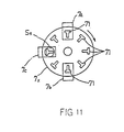
- the revolving cylindrical body 7x is intermittently revolved by a stepping motor 52 and is stopped by the output of a revolving-body-position sensor S5 (see Figure 11) which is positioned to face a spoke holding passage 71 not containing a spoke s for deciding the position of the revolving cylindrical body 7x.
- a revolving-body-position sensor S5 see Figure 11
- the revolving cylindrical body 7x has a spoke-receiving section 7a in the part containing the highest spoke holding passage 71, a spoke shooting section 7b position in the part containing the lowest spoke holding passage and a revolving cylindrical body position detecting section 7c positioned in the part between said spoke receiving section 7a and said spoke shooting section 7b.
- a spoke dropped from a chute 61 of a spoke supplying device 6 is received in a groove 3x which corresponds in shape with the groove 3 of the first embodiment and is provided on a fixed arm 162.
- An air cylinder 164 combined with a piston 163 is arranged at the base end of the fixed arm 162. The spoke received in the groove 3x is shifted to the spoke holding passage 71 of the revolving cylindrical body 7x by reciprocating of the piston 63.
- Valve V for supplying air to the air outlet 31, air cylinders 38, 51, 64 and the stepping motor 52, is operated by a predetermined timing program conditioned by the outputs of the spoke passing sensor S1 and revolving-cylindrical-body-position sensor S5.
- the apparatus of the second embodiment is operated as follows. Before shooting out of the spoke, nozzle N is advanced to a predetermined advanced position from its retracted position and stays there.
- the spoke holding passages 71 are positioned as shown in Figure 11 with the spoke holding passage 71 at the lowest part of the revolving cylindrical body 7x, being coaxial with the air outlet 31 and the spoke passing hole 35 of the nozzle N.
- the cylindrical air body T is contacted to the revolving cylindrical body 7x by the reverse-driven air cylinder 51.
- pressure air is blown into the spoke holding passage 71 from the air outlet 31 by opening of the valve V and the spoke s in the spoke holding passage 71 is shot out from the nozzle N into the spoke hole of the hub flange.
- the apparatus of the second embodiment has an advantage that the shooting-out of spokes is continuous. This is because the revolving cylindrical body 7x is intermittently revolved by the stepping motor 52 and each spoke s is shot out every one step of the stepping motor 52. Each time a spoke is shot out, a spoke in the groove 3x is shifted into the spoke holding passage 71 in registration therewith.
- Figures 12 and 13 show a third embodiment of the invention, wherein spoke receiving and holding grooves 3y are formed by recessing the surface of an intermittently revolving cylindrical body 7y at regular positions around the circumference.
- the cylindrical surface of the revolving cylindrical body 7y is covered by a cylindrical cover 73 having an opening part 74 (see Figure 13).
- the revolving cylindrical body 7y revolves inside the cylindrical cover 73.
- the opening part 74 of the cylindrical cover 73 positioned at the top part of the revolving cylindrical body 7y faces the lowest part of the chute 61 of the spoke supplying device 6.
- the spoke supplying device 6 is similar to that of the first-described embodiment.
- the groove 3y positioned at the lowest part of the revolving cylindrical body 7y becomes coaxial with the air outlet 31, whilst the groove positioned at the highest part of the revolving cylindrical body 7y just corresponds with the opening part 74 of the cylindrical cover 73. Consequently, the groove 3 positioned at the highest part of the revolving cylindrical body 7y faces the chute 61.
- the timings of the spoke shooting out and spoke receiving operations are the same as in the second embodiment described hereinbefore.
- the groove 3y has first to third groove parts 3a, 3b, 3c which are the same as in the first embodiment and as shown in Figures 4 to 6 but the third embodiment differs from the first embodiment in that both ends of the groove 3y are open in all positions except at the bottom of the cylindrical body 7y.
- the spoke shooting out and spoke receiving operations are made at the same time as in the second embodiment.
Landscapes
- Engineering & Computer Science (AREA)
- Mechanical Engineering (AREA)
- Feeding Of Articles To Conveyors (AREA)
- Vending Machines For Individual Products (AREA)
- Automatic Assembly (AREA)
- Steering Controls (AREA)
- Turbine Rotor Nozzle Sealing (AREA)
- Measuring Fluid Pressure (AREA)
Abstract
Description
- The present invention relates to a method and apparatus for inserting spokes into spoke holes of hub flanges.
- An example of the field of the invention is disclosed in U.S.Patent No. 4,538,332. The prior document is particularly concerned with inserting spokes into spoke holes provided in the flanges of a hub of a bicycle wheel. As disclosed therein the hub 1 is supported in a horizontal position, for example as shown in Fig. 14 attached hereto. A spoke is inserted into the
spoke holes 11, 12 of eachflange 10a, lob from spokeinserting devices 2 arranged respectively at both sides of the hub. Such spokeinserting devices 2 are mentioned in PCT Laid-Open Gazette No. WO/83/00032 (Japanese Patent Application Laid-Open Gazette No. Sho-58-50091) and are exemplified in Fig. 15 attached hereto. - In accordance with the above-stated prior art, a nozzle N and holder C are constructed in one body and an upwardly opening
groove 3 is provided in said holder C. Thegroove 3 has a means to thread spokes and the holder C reciprocates on a base B as shown in Fig. 15. The spoke received in thegroove 3 is removed from the rear end of thegroove 3 toward the nozzle N and along thegroove 3. Then, the holder C having thegroove 3 is advanced from the base B through a specified stroke and stays there. Like this, thespoke 5 in thegroove 3 automatically threads into the spoke hole in the time that the nozzle N is approaching towards the spoke hole. The said operation for setting position of the hub and said spoke threading operation are repeated thereafter until all the spoke holes are threaded. However, the prior art has the following problem. That is, the spoke-driving-forward means for threading the spoke, received in thegroove 3, from the nozzle N into the spoke hole of one of the flanges of the hub takes the form of a shiftingbody 20 in thegroove 3 and a driving mechanism for reciprocating the shiftingbody 20. Said driving mechanism is formed by abelt 21 winding between a pair of pulleys. - However, the speed of operation of the shifting
body 20 is restricted, because of limitations in the shifting speed of thebelt 21. - Accordingly, the object of the present invention is to provide a method and an apparatus for inserting spokes into the spoke holes in the flange of the hub which is more speedy than was possible in the prior art.
- In accordance with the present invention, the method thereof comprises receiving and holding the spoke in a spoke holding chamber arranged in a spoke shooting out device and aligned with the spoke hole, effectively sealing the spoke holding chamber and shooting the spoke out of the chamber into the spoke hole of the hub flange,via a nozzle, by means of pressure air blown into the chamber.
- In this process, if the point end of the spoke does not exactly coincide with the position of the spoke hole, the spoke is easily and precisely inserted into the spoke hole because micro vibrations perpendicular to the shooting out direction are occurring in the spoke when the latter is shot out by pressure air. By means of this method the spoke shooting operation can be made more speedy than in the case of the prior art, because pressure air shooting out the spokes moves the spokes rapidly.
- The position of the spoke hole does not need to coincide precisely with the point end of the spoke; the spoke is precisely inserted into the spoke hole, because micro vibrations are occurring in the transverse direction thereof.
- Apparatus according to one aspect of the invention includes a spoke-shooting-out device comprising a nozzle for shooting out the spoke from the device into the spoke hole of the hub flange, a holder provided with a groove for receiving the spoke, a groove cover for opening and shutting the groove, a groove cover driving device for opening the groove cover when the spoke is received and shutting the groove when the spoke is to be shot out, an air outlet for blowing out pressure air into the rear end of the groove and a pressure-air control device for enabling the blowing out of pressure air from said air outlet in the groove when the groove cover is shut.
- When, in the preferred embodiment of this apparatus, the spoke is received in the groove and the cover shuts the opening to the groove, pressure air is blown in the groove by operation of an air control means. The spoke is then shot out of the nozzle and the groove cover is reopened. A further spoke is received in the groove and the aforesaid operations are repeated.
- In a further aspect of the invention there is provided a spoke-shooting-out device comprising a nozzle facing the spoke hole of the hub flange, an intermittently revolving cylindrical body arranged at the rear end of the nozzle mounted on a base and having spoke holding passages through the body at regular intervals along a circle coaxial with the revolving cylindrical body, a spoke receiving groove for receiving a spoke dropped from a spoke supplying device and including means for shifting a spoke from the groove into the spoke holding passage at the highest position of the revolving cylindrical body, and an air outlet formed in a cylindrical air body arranged at the rear end of, the revolving cylindrical body for blowing out pressure air in the spoke holding passage rotated at the lowest position of the revolving cylindrical body.
- The operation of the preferred embodiment of this aspect of the invention is as follows. The spoke is shot out by pressure air blown out of the air outlet when the spoke holding passage rotated to the lowest part of the revolving cylindrical body itself becomes coaxial with the nozzle and the air outlet. At that time, the spoke passage rotated to the highest part of the revolving cylindrical body becomes coaxial with the receiving groove so that the spoke waiting in the groove is shifted to the spoke hole positioned at the highest part of the revolving cylindrical body simultaneously with the spoke in the bottom passage being shot out of the revolving cylindrical body. After that, the same operations are repeated.
- This embodiment has the following advantages. At the same time one spoke is shot out of the position at the lowest part of the revolving cylindrical body into the nozzle, the other spoke is shifted to the holding passage positioned at the highest part of the revolving cylindrical body from the groove. By this means the spoke shooting out operation is made continuous.
- In yet a further aspect of the invention there is provided a spoke-shooting-out device comprising a nozzle, facing one of the spoke holes of the hub flange, for shooting the spoke into the spoke hole, an intermittently revolving cylindrical body contacting the rear end of the nozzle, the body having spoke receiving grooves at regular intervals around the cylindrical surface of the revolving cylindrical body, each groove being open at both ends for receiving and shooting a spoke and being held in a predetermined position for shooting out the spoke into the spoke hole, a cylindrical cover having an opening in its top part, said cover sealing the grooves of the revolving cylindrical body except the one at the top, the opening of the cylindrical cover exposing the groove rotated to the highest position of the revolving cylindrical body, a spoke feeding and spoke supplying device for supplying a spoke to the open groove exposed through the cover, and an air outlet formed in a cylindrical air body arranged at the rear end of the revolving cylindrical body for blowing pressure air into the groove rotated to the lowest position of the revolving cylindrical body. The operation of the preferred embodiment of this aspect of the invention is as follows. First of all, the spoke dropped on the chute of the spoke supplying device positioned just overhead of the revolving cylindrical body is received in the groove positioned at the highest part of the revolving cylindrical body and is held in the attitude suitable for being shot out from the nozzle. When the groove is rotated to the lowest part of the revolving cylindrical body, the groove becomes coaxial with the air outlet and the nozzle, and the spoke is shot out. When the spoke is shot out, the other spoke is received in the groove positioned at the highest part of the revolving cylindrical body. This has the advantage that space for the apparatus may be small compared with the previously described arrangement, because the spoke supplying device is arranged just overhead to the revolving cylindrical body.
- Figure 1 is a diagrammatic view of an embodiment of a spoke-shooting-out device according to the invention;
- Figure 2 shows a vertical and longitudinal section of a part of the device of Figure 1 containing a nozzle.
- Figure 3 shows a side view of a part of the embodiment of Figure 1 containing a spoke-supplying chute.
- Figure 4 shows a sketch of a groove provided in the spoke-shooting-out device of Figure 1.
- Figures 4a, 4b show the manner by which a spoke having an attitude such that its head part is upside down is righted with its head uppermost, having been dropped from the chute into the groove.
- Figure 5 shows V-V section of the groove illustrated in Figure 4.
- Figure 6 shows VI-VI section of the groove illustrated in Figure 4.
- Figure 7 shows VII-VII section of the groove illustrated in Figure 4.
- Figure 8 shows a front view of the spoke-shooting-out device.
- Figure 9 shows a flow chart of a computer circuit for controlling the spoke-shooting-out device.
- Figure 10 shows a vertical and longitudinal section of a second embodiment of the present invention.
- Figure 11 shows a perpendicular section of the revolving cylindrical body of the embodiment illustrated in Figure 10.
- Figure 12 shows a vertical and longitudinal section of a third embodiment of a spoke-shooting-out device according to the invention.
- Figure 13 shows' a lateral section of the revolving cylindrical body of the embodiment illustrated in Figure 12.
- Figure 14 shows a sketch of a prior published threading apparatus.
- Figure 15 shows a longitudinal-section diagram of the spoke threading apparatus of Figure 4.
- As previously noted, the present invention involves a method and an apparatus for inserting a spoke into a spoke hole of a hub flange.
- Hereinafter, a first embodiment as shown in Figs. 1-9 is described. Referring to Figure 8, first to fourth spoke-shooting-out
devices hub flange 10a from the first spoke-shooting-out device 2a arranged at left side of the hub 1 and a second spoke s is inserted into a spoke hole from the second spoke-shooting-out device 2b at right side of the hub 1. A third spoke s is inserted into the spoke hole of thehub flange 10a from the third spoke-shooting-outdevice 2c arranged at right side of the hub 1 and the fourth spoke is inserted into the spoke hole from the fourth spoke-shooting-outdevice 2d at left side of the hub 1. The spoke-shooting-out directions are arranged not to intercept each other and the spoke-shooting-outdevices spoke hole 11, 12 in suitable condition. It is necessary that the spoke shooting direction from the spoke-shooting-out device is aligned with the position of thespoke holes 11, 12. - In the course of the spoke inserting operation the hub 1 is revolved by a friction roller driven by means of a stepping motor SM controlled by the output signal of a spoke hole
position detecting means 40. The motor indexes the hub so that the latter stops with the spoke holes 11, 12 coinciding with the trajectories of the spokes. The respective spoke hole position detecting means 40 are withdrawn to a predetermined position away from the detecting position by displacement means 4 prior to the insertion of the spokes into the spoke holes. - The spoke-shooting-out devices are described hereinafter in further detail. A spoke receiving and holding
groove 3 provided in a holder C extends along the length thereof. At the rear end of the holder, furthest from the spoke holes of the hub (labelled "rear end side" in the Figures) the groove widens from aslot portion 3c extending along most of the groove to curvedside wall portions 3b and anopen portion 3a. The groove is shut and opened by agroove cover 30 provided in the holder. On the holder, at the end of the groove (labelled "point end side" in the Figures), remote from theportion 3a, slidable nozzle N is provided. Nozzle N is supported by a connecting cylindrical body G mounted to the end of the holder C. Nozzle N is reciprocated along the connecting cylindrical body G by anair cylinder 38. Associated with thegroove 3 is achute 61, the bottom edge of which is to be aligned with thegroove 3. The length of thegroove 3 is greater than the length of a spoke s. - It is not necessary that the
groove cover 30 perfectly seals the opening of thegroove 3 when it is shut, but thrust-force for shooting-out the spoke s is increased with total sealing. Thechute 61 is provided with an inclined plate for guiding the spokes s by their self-weight into thegroove 3. The side width of thechute 61 is a little shorter than length of a spoke. - The
groove 3 has first, second andthird parts third groove part 3c is formed as T shape, as shown in Figure 5, to receive a spoke with its head part H uppermost in the recess X. Thesecond groove part 3b, as shown in Figure 4b, has bothside walls - Towards the front end of the widened
portion 3a the side walls approach each other to define a pointed end and become vertical, as shown in Figure 4, 4a, 4b. - By the above construction, the side walls are smoothly curved from the horizontal plane to the vertical plane, the width of the
first groove part 3a being larger than two times of the length of the head part H of the spoke s and thefirst groove part 3a being shaped asa rectangular dent or recess. - The
bottom plane 33 of thefirst groove part 3a smoothly slopes down from the front end of the opening to a verticalrear end plane 31a and from oneside wall 33a to the other side wall 33b as shown in Figure 5. - An
air outlet 31 opens into therear end plane 31a. Thegroove cover 30 formed by a rectangular plate reciprocates in a perpendicular direction with respect to the spoke shooting direction, being driven by a pair ofair cylinders 34x. The cylindrical body G mounted on the end of the holder C facing the spoke holes defines an internalspoke passing hole 35 shown in cross section in Figure 7. Nozzle N comprises a sleeve portion which is slidable on the cylindrical body G and a portion which projects beyond the cylindrical body G and has aninternal passage 35 having a cross-section shaped the same as said spoke passinghole 34. The upper end part of the nozzle N is cut away, being defined by aninclined plane 37a as shown in Figure 2. Apivoted covering plate 37 is mounted on the nozzle and is biased onto saidinclined plane 37a to partially close thespoke passing hole 35 while leaving the lower part thereof open. Theair cylinder 38 for reciprocating the nozzle N is mounted to the holder C. The nozzle N is advanced from a retracted position to a predetermined advanced position and stays at the advanced position when a hub 1 is set. In the advanced position the distance between the free end of the nozzle N and arespective flange 10a, 10b is smaller than the length of the spoke s. The nozzle N is retracted to the said retracted position after the spoke s is inserted into the spoke hole. After that, this operation is repeated for the next spoke hole. - As shown in Figure 1, an air valve v is inserted in a pneumatic circuit between an air source and
air outlet 31. Valve V is controlled by control means 5 including anair control device 50. Air valve V also controls the air supplied to theair cylinder 38. - A sensor S₁ for detecting the passage of the spoke through the nozzle is positioned on the nozzle at the inlet plane of the
nozzle passing hole 35. A sensor S₂ for detecting the presence of a spoke in the bottom of thegroove 3 is provided in an aperture in the holder C which intercepts the groove. Sensors S₃ and S₄ are provided for detecting theshutter 30 in its respective closed and open conditions. The sensor S₁ outputs a signal to indicate that a spoke S has passed by said sensor S₁ within an appointed time. If that time elapsed without the signal being produced the spoke shooting operation is stopped. - The
air cylinders air cylinder 38 and, at the same time, the hub 1 is stopped rotating at a predetermined position. Then thegroove cover 30 is opened and remains open until a spoke is received in thegroove 3 from thechute 61 of thespoke supplying device 6. When the spoke s is received in thegroove 3 thecover 30 is shut, theair cylinder 34 is being operated in response to the output signal of the sensor S₂. Theair cylinder 34 is stopped by the output signal of the sensor S₃, which detects that the shutter is closed. After that, air is blown out from theair outlet 31 by operation of the valve V, the latter being opened as a consequence of the signal from sensor S₃. - So, the spoke s is shifted to the end of the nozzle N and then is shot out into the spoke hole of the
hub flange 10a, 10b. - When the spoke has passed through the position of the sensor S₁ the
groove cover 30 is retracted to its opening position from the shutting position by reverse driving theair cylinder 34. The valve V is closed when a signal is received from sensor S₄ indicating that the groove cover is open. After the above process, the spoke inserting process is repeated for the next spoke hole in the hub. - In Figure 9, the dotted line refers to operation by the hub position deciding means. The hub position deciding means 40, as seen in Figure 8, is for detecting the fact that the positions of the nozzle N and the spoke hole are coincident and, when said means 40 detects the fact above-mentioned, the spoke inserting operation starts. The above-described step from the hub position deciding operation to the spoke inserting operation is repeated for each spoke hole.
- In the present embodiment, the inclined
plane bottom wall 33 of thefirst groove part 3a slopes down from oneside wall 33a to the other side wall 33b and slopes down from the front to back of the widened portion of the groove, as above-mentioned. Consequently, if the spoke s drops on theplane bottom wall 33 in an upside-down attitude, as shown in Figure 4a, so that the head part H is directed downward, the head part H lies on the inclinedplane bottom wall 33. The head part H is gradually uprighted as it moves along the surface of theplane bottom wall 33 as shown in Figure 4b. At the second groove part, the head part H is guided by theside walls - The outlet of the nozzle N is reduced by the presence of the covering
plate 37 pressed on theinclined plane 37a, so air pressure for shooting out the spoke s is sufficiently stored. - A
guide plate 62 is disposed on the holder C at and facing the bottom end of thechute 61, so that a spoke s dropped onto thechute 61 is surely directed in thegroove 3. - Figures 10 and 11 show a second embodiment of the present invention. The embodiment is characterised by an intermittently revolving
cylindrical body 7x supported on a base B. - The axis of the revolving
cylindrical body 7x is parallel to the spoke-shooting-out direction. The cylindrical body contains a plurality ofspoke holding passages 71 distributed at regular intervals parallel to the revolving cylindrical body's axis along a circle concentric with the revolving cylindrical body's axis. The cross-section of each spoke holdingpassage 71 is the same as thespoke passing hole 34 of the connecting cylindrical body G of the previously described embodiment, as shown in Figure 7. - Each spoke holding
passage 71 holding a spoke is rotated to a position of the lowest part of the revolvingcylindrical body 7x and faces to theair outlet 31 of a cylindrical air body T. Theair outlet 31, the revolvingcylindrical body 7x and the connecting cylindrical body G supporting nozzle N are mounted on a base B such that when a spoke s is shot out from the nozzle N, theair outlet 31, thespoke holding passage 71 positioned at the lowest part of the revolvingbody 7x and thespoke passing hole 35 of the connecting cylindrical body G are all coaxial. - The revolving
body 7x is biased towards the rear end of the connecting cylindrical body G, fixed to the base B, by aspring 72 disposed at the rear end of the revolvingcylindrical body 7x. - The cylindrical air body T containing the
air outlet 31 is mounted in the base B and is reciprocated by anair cylinder 51 fixed to the base B. - The revolving
cylindrical body 7x is intermittently revolved by a steppingmotor 52 and is stopped by the output of a revolving-body-position sensor S₅ (see Figure 11) which is positioned to face aspoke holding passage 71 not containing a spoke s for deciding the position of the revolvingcylindrical body 7x. Thus, when the position of said spoke holdingpassage 71 and said sensor S₅ are just met, driving of the steppingmotor 52 is stopped for an appointed time. - As shown in Figure 11, in every indexed position the revolving
cylindrical body 7x has a spoke-receivingsection 7a in the part containing the highestspoke holding passage 71, a spoke shooting section 7b position in the part containing the lowest spoke holding passage and a revolving cylindrical bodyposition detecting section 7c positioned in the part between said spoke receivingsection 7a and said spoke shooting section 7b. In registration with thespoke receiving section 7a, a spoke dropped from achute 61 of aspoke supplying device 6 is received in a groove 3x which corresponds in shape with thegroove 3 of the first embodiment and is provided on afixed arm 162. Anair cylinder 164 combined with apiston 163 is arranged at the base end of the fixedarm 162. The spoke received in the groove 3x is shifted to thespoke holding passage 71 of the revolvingcylindrical body 7x by reciprocating of the piston 63. - Valve V, for supplying air to the
air outlet 31,air cylinders motor 52, is operated by a predetermined timing program conditioned by the outputs of the spoke passing sensor S₁ and revolving-cylindrical-body-position sensor S₅. - The apparatus of the second embodiment is operated as follows. Before shooting out of the spoke, nozzle N is advanced to a predetermined advanced position from its retracted position and stays there. The
spoke holding passages 71 are positioned as shown in Figure 11 with thespoke holding passage 71 at the lowest part of the revolvingcylindrical body 7x, being coaxial with theair outlet 31 and thespoke passing hole 35 of the nozzle N. At that time, the cylindrical air body T is contacted to the revolvingcylindrical body 7x by the reverse-drivenair cylinder 51. After that, pressure air is blown into thespoke holding passage 71 from theair outlet 31 by opening of the valve V and the spoke s in thespoke holding passage 71 is shot out from the nozzle N into the spoke hole of the hub flange. After shooting out of the spoke s, the contact between the cylindrical air body T and revolvingcylindrical body 7x is released by the normally-driven air cylinder, based on the output of the spoke passing sensor S₁, and at the same time the revolvingcylindrical body 7x is revolved for one step by the operation of the steppingmotor 52. - When, as a result of revolving the
cylindrical body 7x, the following spoke holdingpassage 71 is aligned with the position of the revolving body position sensor S₅, the steppingmotor 52 is stopped by the output of the sensor S₅. Then, as thespoke holding passage 71 positioned at the highest part of the revolvingcylindrical body 7x does not have the spoke s, the spoke received in the groove 3x is shifted into thespoke holding passage 71 by thepiston 163 driven by theair cylinder 164. At the same time thespoke holding passage 71 positioned at the lowest part of the revolvingcylindrical body 7x becomes coaxial with theair outlet 31 and the spoke contained therein is shot out. The above operations are made by a micro computer in a similar manner to that of the first-described embodiment. - The apparatus of the second embodiment has an advantage that the shooting-out of spokes is continuous. This is because the revolving
cylindrical body 7x is intermittently revolved by the steppingmotor 52 and each spoke s is shot out every one step of the steppingmotor 52. Each time a spoke is shot out, a spoke in the groove 3x is shifted into thespoke holding passage 71 in registration therewith. - Figures 12 and 13 show a third embodiment of the invention, wherein spoke receiving and holding grooves 3y are formed by recessing the surface of an intermittently revolving
cylindrical body 7y at regular positions around the circumference. The cylindrical surface of the revolvingcylindrical body 7y is covered by acylindrical cover 73 having an opening part 74 (see Figure 13). The revolvingcylindrical body 7y revolves inside thecylindrical cover 73. The openingpart 74 of thecylindrical cover 73 positioned at the top part of the revolvingcylindrical body 7y faces the lowest part of thechute 61 of thespoke supplying device 6. The spoke supplyingdevice 6 is similar to that of the first-described embodiment. - When the revolving
cylindrical body 7y intermittently revolves and stops, the groove 3y positioned at the lowest part of the revolvingcylindrical body 7y becomes coaxial with theair outlet 31, whilst the groove positioned at the highest part of the revolvingcylindrical body 7y just corresponds with the openingpart 74 of thecylindrical cover 73. Consequently, thegroove 3 positioned at the highest part of the revolvingcylindrical body 7y faces thechute 61. The timings of the spoke shooting out and spoke receiving operations are the same as in the second embodiment described hereinbefore. - The groove 3y has first to
third groove parts cylindrical body 7y. In this embodiment the spoke shooting out and spoke receiving operations are made at the same time as in the second embodiment.
Claims (8)
Priority Applications (1)
| Application Number | Priority Date | Filing Date | Title |
|---|---|---|---|
| AT90311235T ATE100765T1 (en) | 1989-10-20 | 1990-10-12 | DEVICE FOR INSERTING WIRE SPOKES INTO THE HOLES OF A WHEEL HUB. |
Applications Claiming Priority (2)
| Application Number | Priority Date | Filing Date | Title |
|---|---|---|---|
| JP274452/89 | 1989-10-20 | ||
| JP1274452A JPH0692048B2 (en) | 1989-10-20 | 1989-10-20 | Spoke embossing method and apparatus for implementing the same |
Publications (2)
| Publication Number | Publication Date |
|---|---|
| EP0424050A1 true EP0424050A1 (en) | 1991-04-24 |
| EP0424050B1 EP0424050B1 (en) | 1994-01-26 |
Family
ID=17541889
Family Applications (1)
| Application Number | Title | Priority Date | Filing Date |
|---|---|---|---|
| EP90311235A Expired - Lifetime EP0424050B1 (en) | 1989-10-20 | 1990-10-12 | Method and apparatus for inserting spokes into spoke-receiving holes in a flange of a hub |
Country Status (6)
| Country | Link |
|---|---|
| US (1) | US5081755A (en) |
| EP (1) | EP0424050B1 (en) |
| JP (1) | JPH0692048B2 (en) |
| CN (1) | CN1023551C (en) |
| AT (1) | ATE100765T1 (en) |
| DE (1) | DE69006310T2 (en) |
Cited By (5)
| Publication number | Priority date | Publication date | Assignee | Title |
|---|---|---|---|---|
| NL1006988C2 (en) | 1997-09-10 | 1999-03-11 | Holland Mechanics Bv | Device and method for filling hubs of a spoked wheel. |
| WO1999012754A1 (en) * | 1997-09-10 | 1999-03-18 | Holland Mechanics B.V. | Apparatus and method for inserting spokes in holes of a hub flange |
| EP0933234A3 (en) * | 1998-01-29 | 2001-01-17 | Araya Kogyo Kabushiki-Kaisya | Spoke inserting apparatus |
| EP2386381A1 (en) * | 2010-05-10 | 2011-11-16 | silcoplan engineering GmbH | Stripping cartridge |
| WO2023017216A1 (en) | 2021-08-13 | 2023-02-16 | Bikebotix | Device for supplying spokes from a spoke-ejecting gun into holes in a hub of a spoked wheel |
Families Citing this family (2)
| Publication number | Priority date | Publication date | Assignee | Title |
|---|---|---|---|---|
| CN108032048B (en) * | 2017-11-29 | 2019-10-22 | 淮北市腾威机械设备有限公司 | A kind of automated machine equipment for spoke conveying installation |
| FR3115727B1 (en) * | 2020-11-02 | 2022-10-07 | Mach 1 | Installation and method for threading spokes in a hub with two flanges of a spoked wheel |
Citations (2)
| Publication number | Priority date | Publication date | Assignee | Title |
|---|---|---|---|---|
| FR2153077A1 (en) * | 1971-09-17 | 1973-04-27 | Meiklejohn Co Ltd I G | |
| DE3103552A1 (en) * | 1981-02-03 | 1982-09-23 | CPM France, Epagny, Annecy | Method and device for attaching wire spokes to the circles of holes on wheel hubs, in particular for bicycles |
Family Cites Families (4)
| Publication number | Priority date | Publication date | Assignee | Title |
|---|---|---|---|---|
| SE434717B (en) * | 1980-09-04 | 1984-08-13 | Monark Crescent Ab | DEVICE FOR AUTOMATIC ASSEMBLY OF WHEELS |
| FR2507969B1 (en) * | 1981-06-19 | 1985-07-19 | Carminati Julien | METHOD AND DEVICE FOR THREADING SPOKES ON A SPOKED WHEEL HUB |
| FR2508390A1 (en) * | 1981-06-24 | 1982-12-31 | Carminati Julien | DEVICE FOR POSITIONING AND INSERTING SPOKES IN THE HOLES OF A SPOKED WHEEL HUB |
| SE439276B (en) * | 1983-10-13 | 1985-06-10 | Monark Crescent Ab | SET AND DEVICE FOR POSSIBLE QUICK ATTENTION AND SUBSEQUENT FIXING OF SPREADS ASSEMBLED IN AN EXTRA WHEEL |
-
1989
- 1989-10-20 JP JP1274452A patent/JPH0692048B2/en not_active Expired - Fee Related
-
1990
- 1990-10-12 EP EP90311235A patent/EP0424050B1/en not_active Expired - Lifetime
- 1990-10-12 DE DE69006310T patent/DE69006310T2/en not_active Expired - Fee Related
- 1990-10-12 AT AT90311235T patent/ATE100765T1/en not_active IP Right Cessation
- 1990-10-19 CN CN90108575A patent/CN1023551C/en not_active Expired - Fee Related
- 1990-10-22 US US07/600,845 patent/US5081755A/en not_active Expired - Lifetime
Patent Citations (2)
| Publication number | Priority date | Publication date | Assignee | Title |
|---|---|---|---|---|
| FR2153077A1 (en) * | 1971-09-17 | 1973-04-27 | Meiklejohn Co Ltd I G | |
| DE3103552A1 (en) * | 1981-02-03 | 1982-09-23 | CPM France, Epagny, Annecy | Method and device for attaching wire spokes to the circles of holes on wheel hubs, in particular for bicycles |
Cited By (8)
| Publication number | Priority date | Publication date | Assignee | Title |
|---|---|---|---|---|
| NL1006988C2 (en) | 1997-09-10 | 1999-03-11 | Holland Mechanics Bv | Device and method for filling hubs of a spoked wheel. |
| WO1999012754A1 (en) * | 1997-09-10 | 1999-03-18 | Holland Mechanics B.V. | Apparatus and method for inserting spokes in holes of a hub flange |
| US6401337B1 (en) | 1997-09-10 | 2002-06-11 | Holland Mechanics B.V | Apparatus and method for inserting spokes in holes of a hub flange |
| EP0933234A3 (en) * | 1998-01-29 | 2001-01-17 | Araya Kogyo Kabushiki-Kaisya | Spoke inserting apparatus |
| CN1139500C (en) * | 1998-01-29 | 2004-02-25 | 新家工业株式会社 | Spok inserting apparatus |
| EP2386381A1 (en) * | 2010-05-10 | 2011-11-16 | silcoplan engineering GmbH | Stripping cartridge |
| WO2023017216A1 (en) | 2021-08-13 | 2023-02-16 | Bikebotix | Device for supplying spokes from a spoke-ejecting gun into holes in a hub of a spoked wheel |
| FR3126103A1 (en) * | 2021-08-13 | 2023-02-17 | Bikebotix | Device for feeding spokes from a spoke ejector gun into holes in a hub of a spoked wheel |
Also Published As
| Publication number | Publication date |
|---|---|
| DE69006310T2 (en) | 1994-09-01 |
| EP0424050B1 (en) | 1994-01-26 |
| JPH03202233A (en) | 1991-09-04 |
| JPH0692048B2 (en) | 1994-11-16 |
| CN1051016A (en) | 1991-05-01 |
| CN1023551C (en) | 1994-01-19 |
| ATE100765T1 (en) | 1994-02-15 |
| US5081755A (en) | 1992-01-21 |
| DE69006310D1 (en) | 1994-03-10 |
Similar Documents
| Publication | Publication Date | Title |
|---|---|---|
| US5911449A (en) | Semi-automated needle feed method and apparatus | |
| US5664404A (en) | Automatic zipper package winding and packaging machine | |
| EP0424050A1 (en) | Method and apparatus for inserting spokes into spoke-receiving holes in a flange of a hub | |
| US5661954A (en) | Needle feed wheel and needle transfer mechanism | |
| US5616082A (en) | Apparatus for assembling a fastener to a washer | |
| US6032343A (en) | Automated swage wind and packaging machine | |
| US20040148993A1 (en) | Wire rod-forming machine | |
| EP0667121A2 (en) | Needly threading and swaging system | |
| CN106270271B (en) | The full-automatic closing device of Closely locking nut | |
| US5323530A (en) | Apparatus for assembling rotors | |
| JPH0555405B2 (en) | ||
| CN107900640A (en) | A kind of commutator assembly automatic assembling machine | |
| JPH01288514A (en) | Molded form delivery device | |
| JP4282675B2 (en) | Electronic component inspection system | |
| US5479980A (en) | Method and device for forming drilled needle blanks | |
| US5937504A (en) | Stand alone swage dial assembly | |
| JPH0640544A (en) | Parts separating / conveying apparatus and method thereof | |
| US3563361A (en) | Setscrew feeding, orienting and driving system | |
| JPH10120147A (en) | Device and method for orientating parts | |
| CN113601041B (en) | Self-adjusting clamping alignment marking machine | |
| CN115741084A (en) | Safety valve handle assembly machine | |
| JP3273916B2 (en) | Analysis pretreatment system | |
| JPH11208206A (en) | Spoke insertion device | |
| US6948237B2 (en) | Methods for manufacturing film cartridge and for feeding plate material | |
| CN218821929U (en) | Dart automatic assembly device and dart automatic production equipment |
Legal Events
| Date | Code | Title | Description |
|---|---|---|---|
| PUAI | Public reference made under article 153(3) epc to a published international application that has entered the european phase |
Free format text: ORIGINAL CODE: 0009012 |
|
| AK | Designated contracting states |
Kind code of ref document: A1 Designated state(s): AT BE CH DE FR GB LI NL SE |
|
| 17P | Request for examination filed |
Effective date: 19910805 |
|
| 17Q | First examination report despatched |
Effective date: 19921207 |
|
| GRAA | (expected) grant |
Free format text: ORIGINAL CODE: 0009210 |
|
| AK | Designated contracting states |
Kind code of ref document: B1 Designated state(s): AT BE CH DE FR GB LI NL SE |
|
| PG25 | Lapsed in a contracting state [announced via postgrant information from national office to epo] |
Ref country code: BE Effective date: 19940126 Ref country code: CH Effective date: 19940126 Ref country code: SE Effective date: 19940126 Ref country code: LI Effective date: 19940126 Ref country code: AT Effective date: 19940126 |
|
| REF | Corresponds to: |
Ref document number: 100765 Country of ref document: AT Date of ref document: 19940215 Kind code of ref document: T |
|
| REF | Corresponds to: |
Ref document number: 69006310 Country of ref document: DE Date of ref document: 19940310 |
|
| ET | Fr: translation filed | ||
| REG | Reference to a national code |
Ref country code: CH Ref legal event code: PL |
|
| PLBE | No opposition filed within time limit |
Free format text: ORIGINAL CODE: 0009261 |
|
| STAA | Information on the status of an ep patent application or granted ep patent |
Free format text: STATUS: NO OPPOSITION FILED WITHIN TIME LIMIT |
|
| 26N | No opposition filed | ||
| REG | Reference to a national code |
Ref country code: GB Ref legal event code: IF02 |
|
| PGFP | Annual fee paid to national office [announced via postgrant information from national office to epo] |
Ref country code: DE Payment date: 20071004 Year of fee payment: 18 Ref country code: NL Payment date: 20071015 Year of fee payment: 18 |
|
| PGFP | Annual fee paid to national office [announced via postgrant information from national office to epo] |
Ref country code: FR Payment date: 20071009 Year of fee payment: 18 Ref country code: GB Payment date: 20071010 Year of fee payment: 18 |
|
| GBPC | Gb: european patent ceased through non-payment of renewal fee |
Effective date: 20081012 |
|
| NLV4 | Nl: lapsed or anulled due to non-payment of the annual fee |
Effective date: 20090501 |
|
| REG | Reference to a national code |
Ref country code: FR Ref legal event code: ST Effective date: 20090630 |
|
| PG25 | Lapsed in a contracting state [announced via postgrant information from national office to epo] |
Ref country code: NL Free format text: LAPSE BECAUSE OF NON-PAYMENT OF DUE FEES Effective date: 20090501 |
|
| PG25 | Lapsed in a contracting state [announced via postgrant information from national office to epo] |
Ref country code: DE Free format text: LAPSE BECAUSE OF NON-PAYMENT OF DUE FEES Effective date: 20090501 |
|
| PG25 | Lapsed in a contracting state [announced via postgrant information from national office to epo] |
Ref country code: FR Free format text: LAPSE BECAUSE OF NON-PAYMENT OF DUE FEES Effective date: 20081031 |
|
| PG25 | Lapsed in a contracting state [announced via postgrant information from national office to epo] |
Ref country code: GB Free format text: LAPSE BECAUSE OF NON-PAYMENT OF DUE FEES Effective date: 20081012 |