EP0423622A1 - Detector having self-calibration function - Google Patents
Detector having self-calibration function Download PDFInfo
- Publication number
- EP0423622A1 EP0423622A1 EP90119524A EP90119524A EP0423622A1 EP 0423622 A1 EP0423622 A1 EP 0423622A1 EP 90119524 A EP90119524 A EP 90119524A EP 90119524 A EP90119524 A EP 90119524A EP 0423622 A1 EP0423622 A1 EP 0423622A1
- Authority
- EP
- European Patent Office
- Prior art keywords
- detection means
- detector system
- stimulating
- signal
- calibration
- Prior art date
- Legal status (The legal status is an assumption and is not a legal conclusion. Google has not performed a legal analysis and makes no representation as to the accuracy of the status listed.)
- Granted
Links
Images


Classifications
-
- G—PHYSICS
- G01—MEASURING; TESTING
- G01D—MEASURING NOT SPECIALLY ADAPTED FOR A SPECIFIC VARIABLE; ARRANGEMENTS FOR MEASURING TWO OR MORE VARIABLES NOT COVERED IN A SINGLE OTHER SUBCLASS; TARIFF METERING APPARATUS; MEASURING OR TESTING NOT OTHERWISE PROVIDED FOR
- G01D5/00—Mechanical means for transferring the output of a sensing member; Means for converting the output of a sensing member to another variable where the form or nature of the sensing member does not constrain the means for converting; Transducers not specially adapted for a specific variable
- G01D5/12—Mechanical means for transferring the output of a sensing member; Means for converting the output of a sensing member to another variable where the form or nature of the sensing member does not constrain the means for converting; Transducers not specially adapted for a specific variable using electric or magnetic means
- G01D5/14—Mechanical means for transferring the output of a sensing member; Means for converting the output of a sensing member to another variable where the form or nature of the sensing member does not constrain the means for converting; Transducers not specially adapted for a specific variable using electric or magnetic means influencing the magnitude of a current or voltage
- G01D5/24—Mechanical means for transferring the output of a sensing member; Means for converting the output of a sensing member to another variable where the form or nature of the sensing member does not constrain the means for converting; Transducers not specially adapted for a specific variable using electric or magnetic means influencing the magnitude of a current or voltage by varying capacitance
- G01D5/241—Mechanical means for transferring the output of a sensing member; Means for converting the output of a sensing member to another variable where the form or nature of the sensing member does not constrain the means for converting; Transducers not specially adapted for a specific variable using electric or magnetic means influencing the magnitude of a current or voltage by varying capacitance by relative movement of capacitor electrodes
- G01D5/2417—Mechanical means for transferring the output of a sensing member; Means for converting the output of a sensing member to another variable where the form or nature of the sensing member does not constrain the means for converting; Transducers not specially adapted for a specific variable using electric or magnetic means influencing the magnitude of a current or voltage by varying capacitance by relative movement of capacitor electrodes by varying separation
-
- G—PHYSICS
- G01—MEASURING; TESTING
- G01D—MEASURING NOT SPECIALLY ADAPTED FOR A SPECIFIC VARIABLE; ARRANGEMENTS FOR MEASURING TWO OR MORE VARIABLES NOT COVERED IN A SINGLE OTHER SUBCLASS; TARIFF METERING APPARATUS; MEASURING OR TESTING NOT OTHERWISE PROVIDED FOR
- G01D18/00—Testing or calibrating apparatus or arrangements provided for in groups G01D1/00 - G01D15/00
- G01D18/002—Automatic recalibration
- G01D18/006—Intermittent recalibration
-
- G—PHYSICS
- G01—MEASURING; TESTING
- G01P—MEASURING LINEAR OR ANGULAR SPEED, ACCELERATION, DECELERATION, OR SHOCK; INDICATING PRESENCE, ABSENCE, OR DIRECTION, OF MOVEMENT
- G01P21/00—Testing or calibrating of apparatus or devices covered by the preceding groups
-
- G—PHYSICS
- G01—MEASURING; TESTING
- G01P—MEASURING LINEAR OR ANGULAR SPEED, ACCELERATION, DECELERATION, OR SHOCK; INDICATING PRESENCE, ABSENCE, OR DIRECTION, OF MOVEMENT
- G01P15/00—Measuring acceleration; Measuring deceleration; Measuring shock, i.e. sudden change of acceleration
- G01P15/02—Measuring acceleration; Measuring deceleration; Measuring shock, i.e. sudden change of acceleration by making use of inertia forces using solid seismic masses
- G01P15/08—Measuring acceleration; Measuring deceleration; Measuring shock, i.e. sudden change of acceleration by making use of inertia forces using solid seismic masses with conversion into electric or magnetic values
- G01P2015/0805—Measuring acceleration; Measuring deceleration; Measuring shock, i.e. sudden change of acceleration by making use of inertia forces using solid seismic masses with conversion into electric or magnetic values being provided with a particular type of spring-mass-system for defining the displacement of a seismic mass due to an external acceleration
- G01P2015/0822—Measuring acceleration; Measuring deceleration; Measuring shock, i.e. sudden change of acceleration by making use of inertia forces using solid seismic masses with conversion into electric or magnetic values being provided with a particular type of spring-mass-system for defining the displacement of a seismic mass due to an external acceleration for defining out-of-plane movement of the mass
- G01P2015/0825—Measuring acceleration; Measuring deceleration; Measuring shock, i.e. sudden change of acceleration by making use of inertia forces using solid seismic masses with conversion into electric or magnetic values being provided with a particular type of spring-mass-system for defining the displacement of a seismic mass due to an external acceleration for defining out-of-plane movement of the mass for one single degree of freedom of movement of the mass
- G01P2015/0828—Measuring acceleration; Measuring deceleration; Measuring shock, i.e. sudden change of acceleration by making use of inertia forces using solid seismic masses with conversion into electric or magnetic values being provided with a particular type of spring-mass-system for defining the displacement of a seismic mass due to an external acceleration for defining out-of-plane movement of the mass for one single degree of freedom of movement of the mass the mass being of the paddle type being suspended at one of its longitudinal ends
Definitions
- the present invention relates to a detector for detecting a physical quantity from a value of an electric signal converted from the physical quantity, and, more particularly, to a detector having a self-calibration function and a characteristic corrective function.
- a conventional detector has been, as disclosed in, for example, Japanese Patent Unexamined Publication No. 61-31952, arranged in such a manner that the measuring operation is stopped so as to start a calibrating operation which is performed as the offline work. Furthermore, there has been disclosed, in Japanese Patent Unexamination Publication No. 61-212753, an apparatus capable of diagnosing deterioration by analyzing the characteristics observed in the detector. However, the apparatus of this type also performs, as the offline work, the operation for diagnosing the deterioration.
- the conventional calibration has been realized for the purpose of automating the offline work. Further technicallymore, there has been a proposal that the reliability of a detector is improved by observing the line and giving an alarm if necessary as the online work. However, since no measure has been taken for performing the calibration as the online work, a problem takes place that the measurement is stopped for a relatively long time in comparison with the time in which the value of the measurement can be changed.
- An object of the present invention is to provide a detector capable of performing a self-calibration as the online work.
- Another object of the present invention is to provide a detector system which can subject a significantly wide portion or a multiplicity of portions to calibration and correction from a remote position and which can be easily maintained and safely operated.
- a still further object of the present invention is to provide a compact detector which is provided with self-calibration and corrective functions and which can be easily manufactured.
- the calibration or the corrective operation must be completed in a significantly short time in comparison with the time in which the value of the measurement can be changed.
- the reason for this lies in that the data of the measurement must be protected from a disorder or an error due to the calibration or the corrective operation performed during the measurement operation.
- the device for processing an electric signal significantly high speed semiconductor ICs are available recently due to the progress of the LSI technology. Therefore, the thus realized speed of processing the electric signal can cope with the time of several tens to 100 ⁇ s which is the value necessary to conduct measurements in automobile in which the values to be measured are varied in a relatively short time. Therefore, unsolved problem is to shorten the time taken to operate the detection means.
- the present invention employs stimulating means disposed adjacent to the detection means so as to stimulate and operate the detection means.
- a structure can be realized in which a small sensor or detector, the size of which is, for example, several hundreds of ⁇ m, and an actuator, that is, the stimulating device can be integrally formed by utilizing the micromachining technology for silicone or the like which has been remarkably progressed recently. Therefore, a compact and integrally formed stimulating device is able to apply a calibration signal, as a stimulation, to the detector without delay.
- a structure is employed in which a calibration signal is supplied to the detector by a signal processing circuit including an accurate and high resolution analog-to-digital converter. Then, a responding electric signal which is inherent to the detector is then processed. Furthermore, a suitable self-calibration algorithm is accurately and quickly performed by a microcomputer.
- a structure is employed according to an embodiment of the present invention, in which the processing device is provided with a communication function, the self-calibration and characteristics correction are instructed from a remote position by another communication device and the result of the self-calibration and the characteristic correction are confirmed.
- the detector according to the present invention is preferably structured such that the stimulating means is formed adjacent to and integrally with the detection means so that the calibration signal can be supplied through the stimulating means. Therefore, the delay of response from the detector can be significantly prevented. Furthermore, a high-speed signal processing circuit can be employed to shorten the time required for completing the self-calibration in comparison to the time in which the values to be measured are changed. Therefore, even if the self-calibration is performed during the measurement operation, the output from the detector can be protected from disorder. Therefore, a so-called "online calibration" can be realized.
- the characteristics obtained during operation are always corrected in accordance with a comparison made with the initial characteristics of the detector based on a calibration and corrective algorithm previously prepared in the processing means. Therefore, the initial performance can be maintained to significantly improve the reliability.
- Reference numeral 1 represents detection means and 2 represents stimulating means disposed adjacent to the detection means 2 and integrally therewith.
- Reference numeral 3 represents an assembly of the detection means 1 and the stimulating means 2.
- Reference numeral 4 represents a signal processing means structured as shown in Fig. 2 and arranged to supply a power supply voltage Ex for operating the detection means 1 and the stimulating means 2 and to process a calibrating signal to be supplied to the stimulating means 2. Furthermore, the signal processing means 4 has a so-called “signal adjustment function" capable of amplifying/converting a responding output signal from the detection means 1.
- the signal processing means 4 has a function of calibrating the input/output and a characteristic corrective function realized by digital-data processing performed by a microcomputer 44.
- Reference numeral 5 represents a detector including the above-described elements. Usually, the detector converts an input physical quantity such as a pressure, a discharge and an acceleration into a digital quantity of a certain number of bits so as to output it.
- Reference numeral 7 represents a communication device capable of transmitting/receiving a command signal and an output signal to and from the signal processing means 4, the communication device 7 further having a function of displaying the comnand signal and the output signal.
- Fig. 2 illustrates the specific structure of a circuit serving as the signal processing means 4.
- a multiplexer 411 is operated so as to cause the output signal transmitted from the detection means 1 to be received by an amplifier 412a and an analog-to-digital converter 42.
- the output signal thus received is converted into a digital signal.
- the signal processing means 4 supplies the power supply voltage Ex or supplies the calibration signal to the stimulating means 2 via another amplifier 421b. As a result, an accurate detection signal capable of correcting an error can be obtained.
- the electrostatic capacity type pressure sensor is constituted in such a manner that an electrode plate 2, which can be displaced by a differential pressure ⁇ P, is disposed between electrode plates 1a and 1b each of which has an area A.
- the distance between each pair of the electrode plates is X0 under no differential pressure.
- each of the spaces between the electrodes is filled with a substance having a dielectric constant ⁇ .
- the capacity difference ⁇ C due to the differential pressure can be detected by the following equation: where symbol E denotes excitation voltage, e denotes voltage to be detected and ⁇ C stands for C2 - C1.
- the voltage can be expressed by the loaded differential pressure ⁇ P as follows:
- detected voltage e max that is, the output span under the maximum differential pressure ⁇ P max is changed as the time proceeds if the compliance k is changed as the time proceeds.
- the voltage V of the intermediate electrode is applied so as to generate a displacement ⁇ xv due to the electrostatic force, so that the output voltage e generated at this time is measured for the purpose of calibrating the above-described span change based on the relationships thus obtained.
- the output voltage e at this time is of a level given by the following equation:
- Figs. 7A and 7B illustrate flow charts for a process to be performed in the microcomputer.
- Fig. 7A illustrates the main routine in which the ordinary measurement work flows along a route 1.
- the calibration voltage e which is the final detected value, is obtained.
- the above-described calibration coefficient d is calculated in a route 2.
- the program for the microcomputer is provided with a calibration measuring sub-routine shown in Fig. 7B, in which the differential value ⁇ e between the detection voltages e1 and e2 is calculated, the detection voltages e1 and e2 being obtained from measurements in which the calibrating pulse voltages V1 and V2 are applied.
- the calibration includes an initial calibration and an optional calibration.
- the initial calibration is performed at the delivery of the product from a manufacturing plant and conducted such that an initial differential value ( ⁇ e-init) is calculated and stored by the process of a route 3.
- the route 2 is performed as the optional calibration in which present differential value ( ⁇ e-present) is calculated so as to obtain the calibration coefficient d which is the ratio to ⁇ e-init.
- the calibration coefficient d thus obtained is stored so as to update the previous value.
- the pressure, the sensitivity drift of which is corrected by the calibration voltage obtained by multiplying the detection voltage e by the calibration coefficient d can be obtained.
- Figs. 8 and 9 respectively illustrate basic structures of semiconductor acceleration sensors of an electrostatic capacity type and of a piezoelectric resistance type, which are two typical types, the sensors being manufactured by a silicone micromachining technology.
- the acceleration sensor is for obtaining an acceleration by a measurement of an inertia force acting on a predetermined mass in the case where the acceleration exists.
- Each of the acceleration sensors shown in Figs. 8 and 9 is structured such that a load 53 and a cantilever 54 for supporting the load 53 are formed on an intermediate silicone substrate 51 by anisotropic etching.
- k a spring constant
- x the amount of displacement
- the acceleration ⁇ can be obtained from the displacement x.
- the electrostatic capacity type acceleration sensor shown in Fig. 8 includes an upper fixed electrode 55a and a lower fixed electrode 55a formed on the surfaces of the upper substrate 52a and the lower substrate 52b which face the intermediate silicone substrate 51.
- the electrostatic capacity type acceleration sensor acts to measure the acceleration by obtaining the displacement x of the Equation (I) from the electrostatic capacity between the fixed electrodes and the load (movable electrode).
- the piezoelectric resistance type acceleration sensor shown in Fig. 9 is structured such that a gauge portion 58 comprising an impurity diffusion region is formed on the cantilever 54.
- the cantilever 54 is deformed, causing the electric resistance of the gauge portion 58 to be changed by the piezoelectric resistance effect.
- the displacement can be obtained from the electric resistance of the gauge portion so that the acceleration is obtained.
- Equation (III) In the case where p(t) and q(t) are unknown in Equation (III), they can be obtained by generating two different accelerations ⁇ 1 and ⁇ 2 by some method so as to measure the outputs V( ⁇ 1, t) and V( ⁇ 2, t) which correspond to the two accelerations ⁇ 1 and ⁇ 2. Namely, P(t) and q(t) can be obtained from the following simultaneous equation.
- Equation (I) the acceleration ⁇ corresponds to the displacement x of the load in the relationship given by Equation (I). Therefore, determining the acceleration ⁇ 1 and ⁇ 2 becomes equivalent to determining the displacements x1 and x2 which correspond to the accelerations ⁇ 1 and ⁇ 2.
- the predetermined displacements x1 and x2 shown in Equation (5) can be relatively easily realized. That is, the structure may be such that the load is forcibly displaced by an actuator and the characteristics of the sensor output V(x, t) sharply varies at the predetermined certain displacements x1 and x2. As an alternative to this, the structure may be such that any further displacement is inhibited.
- Figs. 10 and 11 illustrate examples of the above-described structures, in which stoppers 60a and 60b are provided for the purpose of preventing any displacement which exceeds a predetermined degree even if an acceleration or an external force acts on the load. If the displacements x1 and x2 obtained when the loads are brought into contact with the stoppers 60a and 60b are previously know, p(t) and q(t) can be obtained from Equations (V) and (VI) by measuring the outputs V(x1, t) and V(x2, t) at this time.
- the displacement of the load is measured and the acceleration is obtained from the displacement thus measured.
- a servo type acceleration sensor is also known as a typical acceleration sensor.
- the servo type acceleration sensor is designed such that the displacement of the load due to an acceleration is measured and a signal representing the displacement is fed back. Furthermore, in response to the signal, the load is given, by some method, a force in the reverse direction in the sensor so that the load is restored to the original position. Since the quantity of the feedback corresponds to the magnitude of the acceleration, the acceleration is obtained from the quantity of the feedback. According to this method, the displacement is substantially constant regardless of the acceleration.
- the displacement is often measured by the electrostatic capacity method or the piezoelectric resistance method.
- force is applied to the load in accordance with the quantity of the feedback by using an electrostatic force or a magnetic force.
- Equation (II) the relationship between the final output signal and the acceleration is usually expressed by Equation (II). It is assumed that a second force F is applied to the load in addition to the force which corresponds to the quantity of the feedback in the servo system.
- Figs. 12 and 13 respectively illustrate specific examples of the structures of the sensor devices.
- Fig. 12 illustrates the structure for measuring a displacement by using the electrostatic capacity
- Fig. 13 illustrates the structure for measuring a displacement by using the piezoelectric resistance device.
- the force according to the quantity of the feedback and the second force are applied to the load by using the electrostatic force for the purpose of forming a servo system.
- Reference numerals 61a and 61b represent electrodes for detecting the electrostatic capacity which corresponds to the displacement.
- Reference numerals 62a and 62b represent electrodes for applying the electrostatic force for the servo effect.
- Reference numerals 63a and 63b represent electrodes for applying the electrostatic force for the purpose of applying the second force to the load. These electrodes can be used in a combined manner by arranging a circuit for the servo system and that for applying the electrostatic force to be of proper structures.
- Equation (VIII) the constant forces F1 and F2 shown in Equation (VIII) can be obtained simply by varying the level of the voltage to be applied to the electrostatic force applying electrodes 63a and 63b. Therefore, the magnitude of each of the forces F1 and F2 can be calculated if the areas of the electrodes, the sizes of the gaps and the level of the voltage to be applied are previously known.
- an advantage can be obtained that the change in the acceleration output characteristics of the servo type acceleration sensor as the time proceeds can be corrected.
- Fig. 14 illustrates the relationship between excess air factor ⁇ , the exhaust gas density and the electromotive force.
- the residual oxygen density is increased with the excess air factor ⁇ in the lean region ( ⁇ > 1), while the density of unburnt gases such as carbon monoxide and hydrogen is increased in the rich region ( ⁇ ⁇ 1) with the decrease in the excess air factor ⁇ .
- the O2 sensor cannot satisfactorily meet the desire of enlarging the output in the rich region and improving the purification of the exhaust gases at the stoichiometrical air-fuel ratio and the economical efficiency in the lean region since the O2 sensor is able to detect only the stoichiometrical air-fuel ratio. Therefore, there has been a demand for an air-fuel ratio sensor capable of continuously and accurately detecting the excess air factor ⁇ over a wide range from the rich region to the lean region in order to achieve a most suitable combustion control of the engine. Accordingly, there has been known an air-fuel ratio sensor which utilizes the diffusion controlling phenomenon of the above-described various gas components in a gas diffusion film and the oxygen pump phenomenon of a zirconia solid electrolyte.
- Fig. 15 illustrates an example of the V-I characteristics of an air-fuel ratio sensor of the type described above, wherein the relationship between exciting voltage E applied to a detection portion and pump electric current I P passing through the detection portion is shown.
- the pump electric current I P exhibits a predetermined value in a certain range of exciting voltage.
- the predetermined value is a value determined by diffusion resistance R in the gas diffusion film and the excess air factor ⁇ , the value being called a "critical current value".
- the excess air factor ⁇ is measured from the level of the critical current value I P .
- the diffusion resistance R varies depending upon the adhesion of dust to the gas diffusion film and microcracks formed in the gas diffusion film, causing the critical current value I P to be varied correspondingly.
- the critical current value is reduced since the diffusion resistance is increased.
- the diffusion resistance is reduced in the case of the microcracks, causing the critical current value to be increased. In either of the above-described two cases, the excess air factor ⁇ cannot be detected accurately.
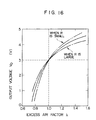
- Fig. 16 illustrates the characteristics obtained by converting the critical current value which corresponds to the excess air factor ⁇ into the output voltage V0.
- the initial characteristics of the air-fuel ratio sensor is shown in the drawing by a continuous or solid line.
- the output characteristics obtained when the diffusion resistance R of the gas diffusion apertures has been increased as the time proceeds are designated by a one-dot line, while the output characteristics obtained when the diffusion resistance R has been decreased are designated by a two-dot line.
- the reason for this lies in that the critical current value is, as shown in Fig. 15, zero at the stoichiometrical air-fuel ratio point.
- the output voltages are varied only in the rich region ( ⁇ ⁇ 1) and the lean region ( ⁇ > 1), that is, only the sensitivity of the air-fuel ratio sensor is changed.
- an air-fuel ratio sensor having a self-diagnosis function will be described with reference to Fig. 17, the air-fuel ratio sensor being designed such that the amount of the change in the characteristic variable of the sensor caused when the calibrating electric signal is applied, is measured and the change in the sensitivity as the time proceeds is corrected in accordance with the electric signal and the amount of the change in the characteristic variable of the sensor.
- the detection portion of the air-fuel ratio sensor comprises a zirconia solid electrolyte 100, porous electrodes 101 and 102 and a gas diffusion film 103.
- the zirconia solid electrolyte 100 is of a tubular shape with the porous electrode 101 formed on the inner surface thereof and the porous electrode 102 and the gas diffusion film 103 formed on the outer surface thereof.
- the porous electrode 101 is exposed to the atmosphere while the porous electrode 102 and the gas diffusion film 103 are exposed to the exhaust gases with the zirconia solid electrolyte 100 acting as a partition wall.
- the detection means comprises a switch 104 and a portion 105 for measuring critical current I P
- the stimulating means comprises a portion 106 for supplying a predetermined current I P *
- a processing means 107 has the self-calibration function and preferably comprises a microcomputer.
- Fig. 17 schematically illustrates that the switch 104 comprises contacts 108, 109 and 110 and is arranged such that the portion 106 for supplying the predetermined current I P * is operated when a connection between the contact 108 and the contact 109 is established and such that, when a connection between the contact 108 and the contact 110 is established, the portion 105 for measuring the critical current I P is operated.
- both the portion 105 for measuring the critical current I P and the portion 106 for supplying the predetermined current I P * are not operated.
- the critical current I P which corresponds to the content of the unburnt gas such as the residual oxygen and the carbon monoxide is measured by the portion 105 for measuring the critical current I P when the contacts 108 and the 110 are connected.
- the portion 106 for supplying the predetermined current I P * is operated.
- the portion 106 for supplying the predetermined current I P * forcibly supplies the calibrating electric signal I P * to the detection portion.
- oxygen of a predetermined quantity which corresponds to the predetermined current I P *, can be supplied from the porous electrode 101, which is exposed to the atmosphere, through the zirconia solid electrolyte 100 to the porous electrode 102, which is exposed to the exhaust gas.
- the oxygen thus supplied is discharged into the exhaust gas from the porous electrode 102 through the gas diffusion film 103. Since the rate of discharge of the oxygen is determined depending upon the diffusion resistance R of the gas diffusion film 103, the change in the sensitivity of the air-fuel ratio sensor as the time proceeds can be diagnosed by measuring the change in the content of the oxygen at the interface between the porous electrode 102 and the gas diffusion portion 103. In the case where the diffusion resistance R of the gas diffusion film 103 is large, the rate of discharge of the oxygen is low, while the discharge rate is high when the diffusion resistance R is small.
- the fact that the oxygen discharge rate is lowered than the initial one is an evidence that the sensitivity of the air-fuel ratio sensor has been deteriorated.
- the fact the rate is raised is an evidence that the sensitivity has been increased.
- the portion 106 for supplying the predetermined current I P * has been operated
- the portion 105 for measuring the critical current I P is intermittently operated in response to a command issued from the self-diagnosis function portion 107.
- the change in the oxygen discharge rate as the time proceeds that is, the change in the diffusion resistance R as the time proceeds
- an accurate output voltage V out corresponding to the excess air factor ⁇ can be obtained by correcting the sensitivity of the air-fuel ratio sensor by the self-diagnosis function portion 107.
- Graph (a) illustrates the output characteristics of the portion 105 for measuring the critical current I P
- (b) illustrates the state of the operation of the portion 105 for measuring the critical current I P
- (c) illustrates the state of the operation of the portion 106 for supplying the predetermined current I P *
- (d) illustrates a state in which the contact 108 is fully opened.
- the connection of the contact 108 in the switch 104 is changed from the contact 110 to the contact 109.
- the portion 106 for supplying the predetermined current I P* is operated for a certain time (to) so that oxygen of a predetermined quantity is forcibly supplied from the porous electrode 101 to the porous electrode 102.
- the portion 105 for measuring the critical current I P is intermittently operated so as to detect the change in the critical current I P caused in the detection portion.
- the current I P detected is gradually decreased as shown by a one-dot line in graph (a). It takes a time ⁇ for the current I P to be lowered to a predetermined level I PC .
- the reason for the decrease in the level of the current I P lies in that oxygen at the interface between the porous electrode 102 and the gas diffusion film 103 is discharged into the exhaust gas, causing the density of the oxygen at the interface to be lowered gradually.
- the self-diagnosis function portion 107 performs the switching correction in such a manner that the sensitivity of the air-fuel ratio sensor is decreased in the former case, while the same is improved in the latter case. As a result, an accurate output voltage V OUT can always be obtained.
- the change in the sensitivity as the time proceeds can be corrected in accordance with the amount of the change in the characteristic variable (I P ) of the air-fuel ratio sensor which is caused due to the calibrating electric signal (I P )* applied.
- the calibration operation can be performed in addition to the measuring operation. Therefore, an accurate output can be detected continuously.
Abstract
Description
- The present invention relates to a detector for detecting a physical quantity from a value of an electric signal converted from the physical quantity, and, more particularly, to a detector having a self-calibration function and a characteristic corrective function.
- Hitherto, a conventional detector has been, as disclosed in, for example, Japanese Patent Unexamined Publication No. 61-31952, arranged in such a manner that the measuring operation is stopped so as to start a calibrating operation which is performed as the offline work. Furthermore, there has been disclosed, in Japanese Patent Unexamination Publication No. 61-212753, an apparatus capable of diagnosing deterioration by analyzing the characteristics observed in the detector. However, the apparatus of this type also performs, as the offline work, the operation for diagnosing the deterioration.
- The conventional calibration has been realized for the purpose of automating the offline work. Furthermore, there has been a proposal that the reliability of a detector is improved by observing the line and giving an alarm if necessary as the online work. However, since no measure has been taken for performing the calibration as the online work, a problem takes place that the measurement is stopped for a relatively long time in comparison with the time in which the value of the measurement can be changed.
- An object of the present invention is to provide a detector capable of performing a self-calibration as the online work.
- Another object of the present invention is to provide a detector system which can subject a significantly wide portion or a multiplicity of portions to calibration and correction from a remote position and which can be easily maintained and safely operated.
- A still further object of the present invention is to provide a compact detector which is provided with self-calibration and corrective functions and which can be easily manufactured.
- In order to achieve the above-described objects, the calibration or the corrective operation must be completed in a significantly short time in comparison with the time in which the value of the measurement can be changed. The reason for this lies in that the data of the measurement must be protected from a disorder or an error due to the calibration or the corrective operation performed during the measurement operation. As for the device for processing an electric signal, significantly high speed semiconductor ICs are available recently due to the progress of the LSI technology. Therefore, the thus realized speed of processing the electric signal can cope with the time of several tens to 100 µs which is the value necessary to conduct measurements in automobile in which the values to be measured are varied in a relatively short time. Therefore, unsolved problem is to shorten the time taken to operate the detection means. Accordingly, the present invention employs stimulating means disposed adjacent to the detection means so as to stimulate and operate the detection means. A structure can be realized in which a small sensor or detector, the size of which is, for example, several hundreds of µm, and an actuator, that is, the stimulating device can be integrally formed by utilizing the micromachining technology for silicone or the like which has been remarkably progressed recently. Therefore, a compact and integrally formed stimulating device is able to apply a calibration signal, as a stimulation, to the detector without delay.
- In order to achieve the other object of the invention, it is necessary to supply an accurate calibration signal to the detector and to correctly measure the response of the detector. Therefore, according to an embodiment of the present invention, a structure is employed in which a calibration signal is supplied to the detector by a signal processing circuit including an accurate and high resolution analog-to-digital converter. Then, a responding electric signal which is inherent to the detector is then processed. Furthermore, a suitable self-calibration algorithm is accurately and quickly performed by a microcomputer.
- In order to achieve the other object of the invention, a structure is employed according to an embodiment of the present invention, in which the processing device is provided with a communication function, the self-calibration and characteristics correction are instructed from a remote position by another communication device and the result of the self-calibration and the characteristic correction are confirmed.
- The detector according to the present invention is preferably structured such that the stimulating means is formed adjacent to and integrally with the detection means so that the calibration signal can be supplied through the stimulating means. Therefore, the delay of response from the detector can be significantly prevented. Furthermore, a high-speed signal processing circuit can be employed to shorten the time required for completing the self-calibration in comparison to the time in which the values to be measured are changed. Therefore, even if the self-calibration is performed during the measurement operation, the output from the detector can be protected from disorder. Therefore, a so-called "online calibration" can be realized.
- Furthermore, the characteristics obtained during operation are always corrected in accordance with a comparison made with the initial characteristics of the detector based on a calibration and corrective algorithm previously prepared in the processing means. Therefore, the initial performance can be maintained to significantly improve the reliability.
- Other and further objects, features and advantages of the invention will be made more apparent by the following description.
-
- Fig. 1 illustrates the basic structure of an embodiment of the present invention;
- Fig. 2 is a circuit diagram for a signal processing means;
- Figs. 3 to 6 illustrate the operation of an electrostatic capacity type pressure sensor;
- Figs. 7A and 7B are flow charts of the operation of a microcomputer;
- Figs. 8 to 11 illustrate the operations of semiconductor acceleration sensors;
- Figs. 12 and 13 illustrate another embodiment of the acceleration sensor;
- Fig. 14 illustrates the characteristics of an air-fuel ratio sensor with respect to an excess air factor;
- Fig. 15 illustrates the voltage-electric current characteristics of the air-fuel ratio sensor;
- Fig. 16 illustrates the output characteristics of the air-fuel ratio sensor;
- Fig. 17 illustrates the structure of a sensor having a self-diagnosis function; and
- Fig. 18 illustrates the self-diagnosis operation.
- Referring to Fig. 1, the basic structure of an embodiment of the present invention will be described.
Reference numeral 1 represents detection means and 2 represents stimulating means disposed adjacent to the detection means 2 and integrally therewith.Reference numeral 3 represents an assembly of the detection means 1 and the stimulatingmeans 2.Reference numeral 4 represents a signal processing means structured as shown in Fig. 2 and arranged to supply a power supply voltage Ex for operating the detection means 1 and the stimulatingmeans 2 and to process a calibrating signal to be supplied to the stimulatingmeans 2. Furthermore, the signal processing means 4 has a so-called "signal adjustment function" capable of amplifying/converting a responding output signal from the detection means 1. In addition, the signal processing means 4 has a function of calibrating the input/output and a characteristic corrective function realized by digital-data processing performed by amicrocomputer 44.Reference numeral 5 represents a detector including the above-described elements. Usually, the detector converts an input physical quantity such as a pressure, a discharge and an acceleration into a digital quantity of a certain number of bits so as to output it.Reference numeral 7 represents a communication device capable of transmitting/receiving a command signal and an output signal to and from the signal processing means 4, thecommunication device 7 further having a function of displaying the comnand signal and the output signal. - Fig. 2 illustrates the specific structure of a circuit serving as the signal processing means 4. In response to a comnand issued from the
microprocessor 44 having amemory 45, amultiplexer 411 is operated so as to cause the output signal transmitted from the detection means 1 to be received by anamplifier 412a and an analog-to-digital converter 42. As a result, the output signal thus received is converted into a digital signal. In accordance with the value represented by the digital signal, the signal processing means 4 supplies the power supply voltage Ex or supplies the calibration signal to the stimulatingmeans 2 via another amplifier 421b. As a result, an accurate detection signal capable of correcting an error can be obtained. - Then, the principle of a span calibration operation will be described with reference to an electrostatic capacity type pressure sensor so as to specifically describe the invention.
- As shown in Fig. 3, the electrostatic capacity type pressure sensor is constituted in such a manner that an
electrode plate 2, which can be displaced by a differential pressure ΔP, is disposed betweenelectrode plates - When the differential pressure ΔP is applied, the intermediate electrode is, as shown in Fig. 4, displaced by ΔX. Since the displacement is substantially in proportion to the differential pressure, the relationship expressed by (ΔX = k · ΔP) is held, where symbol k denotes a compliance (the reciprocal of the spring constant).
- Assuming that K is varied as the time proceeds, it can be expressed as the function of time T, that is, k(T). As a result of the above-described displacement of the
intermediate electrode plate 2, there is generated a capacity difference ΔC between capacities C₁ and C₂, where the capacity C₁ is the capacity between theelectrodes electrodes - As a result of the arrangement of a circuit shown in Fig. 5, the capacity difference ΔC due to the differential pressure can be detected by the following equation:


- As can be seen from the above-described equation (2), detected voltage emax, that is, the output span under the maximum differential pressure ΔPmax is changed as the time proceeds if the compliance k is changed as the time proceeds.
- The voltage V of the intermediate electrode is applied so as to generate a displacement Δxv due to the electrostatic force, so that the output voltage e generated at this time is measured for the purpose of calibrating the above-described span change based on the relationships thus obtained.
- First, calibrating voltage V shown in Fig. 5 is selected in a manner expressed by the following Equation (3):
V = E/2 + v (3) - However, assuming that (v « E/2), the displacement due to the voltage V is of a value expressed by ΔX shown in Fig. 6 and given by the following Equation 4:

- The output voltage e at this time is of a level given by the following equation:

- Therefore, since k(T) can be known by varying V, the span can be calibrated.
- Then, the procedure will be described.
- It is defined that the outputs are e₁ and e₂ when calibrating voltages V₁ and V₂ are applied. In order to delete from Equation (5) the term which depends upon the pressure, the following calculation is performed:

- Then, the proportion to Δe with the initial T being 0 is given as follows:

- By using d thus obtained, calibrating outputcan be obtained from the following equation:

= d · e (where v = 0).
- Figs. 7A and 7B illustrate flow charts for a process to be performed in the microcomputer. Fig. 7A illustrates the main routine in which the ordinary measurement work flows along a
route 1. In theroute 1, the detection voltageat (v = 0) in Equation (5) is measured so as to obtain calibration voltage by multiplying calibration coefficient d. As a result, the calibration voltage e, which is the final detected value, is obtained. The above-described calibration coefficient d is calculated in a
route 2. The program for the microcomputer is provided with a calibration measuring sub-routine shown in Fig. 7B, in which the differential value Δe between the detection voltages e₁ and e₂ is calculated, the detection voltages e₁ and e₂ being obtained from measurements in which the calibrating pulse voltages V₁ and V₂ are applied. - The calibration includes an initial calibration and an optional calibration. The initial calibration is performed at the delivery of the product from a manufacturing plant and conducted such that an initial differential value (Δe-init) is calculated and stored by the process of a
route 3. Theroute 2 is performed as the optional calibration in which present differential value (Δe-present) is calculated so as to obtain the calibration coefficient d which is the ratio to Δe-init. The calibration coefficient d thus obtained is stored so as to update the previous value. - As described above, the pressure, the sensitivity drift of which is corrected by the calibration voltageobtained by multiplying the detection voltage e by the calibration coefficient d, can be obtained.

- Figs. 8 and 9 respectively illustrate basic structures of semiconductor acceleration sensors of an electrostatic capacity type and of a piezoelectric resistance type, which are two typical types, the sensors being manufactured by a silicone micromachining technology.
- The acceleration sensor is for obtaining an acceleration by a measurement of an inertia force acting on a predetermined mass in the case where the acceleration exists. Each of the acceleration sensors shown in Figs. 8 and 9 is structured such that a
load 53 and acantilever 54 for supporting theload 53 are formed on anintermediate silicone substrate 51 by anisotropic etching. When acceleration α is applied, inertia force (E₁ = mα) acts on the load (mass m), causing the load (mass m) to be displaced. On the other hand, the cantilever acts as a spring so that it gives to the load a restoring force expressed by (F₂ = kx) (where symbol k denotes a spring constant and x denotes the amount of displacement), the restoring force being given in the direction reverse to the direction of the displacement. As a result, the load is displaced to the position at which the above-described two forces are balanced. From the relationship expressed by (F₁ = F₂x), the displacement x is given by:
x = md/k (I) - Therefore, the acceleration α can be obtained from the displacement x.
- The electrostatic capacity type acceleration sensor shown in Fig. 8 includes an upper
fixed electrode 55a and a lower fixedelectrode 55a formed on the surfaces of theupper substrate 52a and thelower substrate 52b which face theintermediate silicone substrate 51. The electrostatic capacity type acceleration sensor acts to measure the acceleration by obtaining the displacement x of the Equation (I) from the electrostatic capacity between the fixed electrodes and the load (movable electrode). - On the other hand, the piezoelectric resistance type acceleration sensor shown in Fig. 9 is structured such that a
gauge portion 58 comprising an impurity diffusion region is formed on thecantilever 54. When theload 53 is displaced by an acceleration, thecantilever 54 is deformed, causing the electric resistance of thegauge portion 58 to be changed by the piezoelectric resistance effect. The displacement can be obtained from the electric resistance of the gauge portion so that the acceleration is obtained. - Thus, an output signal V(α) corresponding to the acceleration can be obtained by the signal processing circuit which processes the electrostatic capacity between the load and the fixed electrode or the electric resistance of the gauge portion. Since the output and the acceleration α are usually processed so as to keep a linear relationship, the output V(α) is expressed by the following equation:
V(α) = pα + q (II) - It is assumed that the acceleration sensor is changed as the time proceeds for some reason. If the change takes place with the linear relationship between the acceleration and the output (substantially) maintained, the output becomes the function of the time. Therefore, the output becomes as follows:
V(α, t) = p(t)α + q(t) (III) - If the span p(t) and the zero point q(t) of the acceleration-output characteristics (III) have been correctly known, the acceleration α can be accurately obtained by measuring the output V(α, t).
- In the case where p(t) and q(t) are unknown in Equation (III), they can be obtained by generating two different accelerations α₁ and α₂ by some method so as to measure the outputs V(α₁, t) and V(α₂, t) which correspond to the two accelerations α₁ and α₂. Namely, P(t) and q(t) can be obtained from the following simultaneous equation.

- On the other hand, the acceleration α corresponds to the displacement x of the load in the relationship given by Equation (I). Therefore, determining the acceleration α₁ and α₂ becomes equivalent to determining the displacements x₁ and x₂ which correspond to the accelerations α₁ and α₂. Thus, the following relationships are obtained from Equations (I) and (IV):

The predetermined displacements x₁ and x₂ shown in Equation (5) can be relatively easily realized. That is, the structure may be such that the load is forcibly displaced by an actuator and the characteristics of the sensor output V(x, t) sharply varies at the predetermined certain displacements x₁ and x₂. As an alternative to this, the structure may be such that any further displacement is inhibited. - Figs. 10 and 11 illustrate examples of the above-described structures, in which
stoppers stoppers - In order to displace the load at a desired time so as to bring it into contact with the stoppers in the case of the electrostatic capacity type sensor, voltage is applied between the load and the upper
fixed electrode 55a or the lower fixedelectrode 55b, which acts to obtain the electrostatic capacity, so as to apply the electrostatic force between them. Also in the case of the piezoelectric resistance type sensor, the upperfixed electrode 55a and the lower fixedelectrode 55b are formed and voltage is applied between the load and the upperfixed electrode 55a or the lower fixedelectrode 55b. - As described above, an advantage can be obtained that the change in the acceleration-output characteristics as the time proceeds can be corrected by a simple calculation from the output obtained by periodically applying a voltage between the fixed electrodes and the load. Furthermore, the correction can be performed even if the acceleration is being applied to the sensor.
- According to the above-described embodiments, the displacement of the load is measured and the acceleration is obtained from the displacement thus measured. A servo type acceleration sensor is also known as a typical acceleration sensor. The servo type acceleration sensor is designed such that the displacement of the load due to an acceleration is measured and a signal representing the displacement is fed back. Furthermore, in response to the signal, the load is given, by some method, a force in the reverse direction in the sensor so that the load is restored to the original position. Since the quantity of the feedback corresponds to the magnitude of the acceleration, the acceleration is obtained from the quantity of the feedback. According to this method, the displacement is substantially constant regardless of the acceleration.
- Similarly to the above-described embodiment, the displacement is often measured by the electrostatic capacity method or the piezoelectric resistance method. Furthermore, force is applied to the load in accordance with the quantity of the feedback by using an electrostatic force or a magnetic force.
- In the servo type sensor, the relationship between the final output signal and the acceleration is usually expressed by Equation (II). It is assumed that a second force F is applied to the load in addition to the force which corresponds to the quantity of the feedback in the servo system. The output from the sensor at this time can be expressed by the following equation:
V(α, F) = p(α + F/m) + q (VII) - In the case where forces F₁ and F₂ of predetermined magnitudes are applied, the following relationships are held:

V(α, F₁) - V(α, F₂) = p(F₁ - F₂)/m (IX)
If V(α, F₁), V(α, F₂), F₁, F₂ and m are known, p can be obtained. - When the sensor device is brought into upside down by an actuator such as a motor with the application of the force F (F may be 0) maintained, the direction of each of the acceleration and the second force applied to the sensor is inverted. Therefore, the output becomes as follows:
V(-α, - F) = p(-α - F/m) + q (X)
Adding Equations (7) and (10), the following relationship is obtained:
V(α, F) + V(-α, - F) = 2q (XI)
Therefore, q can be obtained from Equation (XI). - Figs. 12 and 13 respectively illustrate specific examples of the structures of the sensor devices. Fig. 12 illustrates the structure for measuring a displacement by using the electrostatic capacity, while Fig. 13 illustrates the structure for measuring a displacement by using the piezoelectric resistance device. In each of the two structures, the force according to the quantity of the feedback and the second force are applied to the load by using the electrostatic force for the purpose of forming a servo system. Reference numerals 61a and 61b represent electrodes for detecting the electrostatic capacity which corresponds to the displacement.
Reference numerals Reference numerals - Since the displacement of the load is substantially constant in the servo type sensor, the gap between each of the two electrostatic
force applying electrodes force applying electrodes - According to the above-described embodiment, an advantage can be obtained that the change in the acceleration output characteristics of the servo type acceleration sensor as the time proceeds can be corrected.
- Then, an embodiment in which the sensor having a self-diagnosis function is applied to an air-fuel ratio sensor for an automobile will be described below. Fig. 14 illustrates the relationship between excess air factor λ, the exhaust gas density and the electromotive force. As is well known, the residual oxygen density is increased with the excess air factor λ in the lean region (λ > 1), while the density of unburnt gases such as carbon monoxide and hydrogen is increased in the rich region (λ < 1) with the decrease in the excess air factor λ. Hitherto, an O₂ sensor utilizing electromotive force eλ showing step-wise output characteristics around the stoichiometrical air-fuel ratio (λ = 1) has been employed as the key sensor for controlling the engine in order to satisfy the automobile emission gas regulation. However, the O₂ sensor cannot satisfactorily meet the desire of enlarging the output in the rich region and improving the purification of the exhaust gases at the stoichiometrical air-fuel ratio and the economical efficiency in the lean region since the O₂ sensor is able to detect only the stoichiometrical air-fuel ratio. Therefore, there has been a demand for an air-fuel ratio sensor capable of continuously and accurately detecting the excess air factor λ over a wide range from the rich region to the lean region in order to achieve a most suitable combustion control of the engine. Accordingly, there has been known an air-fuel ratio sensor which utilizes the diffusion controlling phenomenon of the above-described various gas components in a gas diffusion film and the oxygen pump phenomenon of a zirconia solid electrolyte.
- Fig. 15 illustrates an example of the V-I characteristics of an air-fuel ratio sensor of the type described above, wherein the relationship between exciting voltage E applied to a detection portion and pump electric current IP passing through the detection portion is shown. As shown in this drawing, the pump electric current IP exhibits a predetermined value in a certain range of exciting voltage. The predetermined value is a value determined by diffusion resistance R in the gas diffusion film and the excess air factor λ, the value being called a "critical current value". The excess air factor λ is measured from the level of the critical current value IP.
- The diffusion resistance R varies depending upon the adhesion of dust to the gas diffusion film and microcracks formed in the gas diffusion film, causing the critical current value IP to be varied correspondingly. In the case of the adhesion of dust to the gas diffusion film, the critical current value is reduced since the diffusion resistance is increased. On the other hand, the diffusion resistance is reduced in the case of the microcracks, causing the critical current value to be increased. In either of the above-described two cases, the excess air factor λ cannot be detected accurately.
- Fig. 16 illustrates the characteristics obtained by converting the critical current value which corresponds to the excess air factor λ into the output voltage V₀. The initial characteristics of the air-fuel ratio sensor is shown in the drawing by a continuous or solid line. The output characteristics obtained when the diffusion resistance R of the gas diffusion apertures has been increased as the time proceeds are designated by a one-dot line, while the output characteristics obtained when the diffusion resistance R has been decreased are designated by a two-dot line. As shown in the drawing, the output voltages at the zero point of the air-fuel ratio sensor, that is, at the stoichiometrical air-fuel ratio point (λ = 1), are not varied. The reason for this lies in that the critical current value is, as shown in Fig. 15, zero at the stoichiometrical air-fuel ratio point. The output voltages are varied only in the rich region (λ < 1) and the lean region (λ > 1), that is, only the sensitivity of the air-fuel ratio sensor is changed.
- Then, an air-fuel ratio sensor having a self-diagnosis function will be described with reference to Fig. 17, the air-fuel ratio sensor being designed such that the amount of the change in the characteristic variable of the sensor caused when the calibrating electric signal is applied, is measured and the change in the sensitivity as the time proceeds is corrected in accordance with the electric signal and the amount of the change in the characteristic variable of the sensor.
- Referring to Fig. 17, the detection portion of the air-fuel ratio sensor comprises a zirconia
solid electrolyte 100,porous electrodes gas diffusion film 103. The zirconiasolid electrolyte 100 is of a tubular shape with theporous electrode 101 formed on the inner surface thereof and theporous electrode 102 and thegas diffusion film 103 formed on the outer surface thereof. Theporous electrode 101 is exposed to the atmosphere while theporous electrode 102 and thegas diffusion film 103 are exposed to the exhaust gases with the zirconiasolid electrolyte 100 acting as a partition wall. - The detection means comprises a
switch 104 and aportion 105 for measuring critical current IP, while the stimulating means comprises aportion 106 for supplying a predetermined current IP*. A processing means 107 has the self-calibration function and preferably comprises a microcomputer. Fig. 17 schematically illustrates that theswitch 104 comprisescontacts portion 106 for supplying the predetermined current IP* is operated when a connection between thecontact 108 and thecontact 109 is established and such that, when a connection between thecontact 108 and thecontact 110 is established, theportion 105 for measuring the critical current IP is operated. When no connection is established between thecontact 108 and any of thecontacts portion 105 for measuring the critical current IP and theportion 106 for supplying the predetermined current IP* are not operated. - The density of the gas contained in the exhaust gases is changed in accordance with the excess air factor λ. Therefore, the critical current IP which corresponds to the content of the unburnt gas such as the residual oxygen and the carbon monoxide is measured by the
portion 105 for measuring the critical current IP when thecontacts 108 and the 110 are connected. The output characteristics of the air-fuel ratio sensor is automatically diagnosed periodically (for example, about every month). That is, if the excess air factor λ continuously shows a predetermined value (preferably the stoichiometrical air-fuel ratio λ = 1) for a considerably long time, the self-diagnosis function portion 107 controls theswitch 104 so as to establish a connection between thecontacts portion 106 for supplying the predetermined current IP* is operated. Theportion 106 for supplying the predetermined current IP* forcibly supplies the calibrating electric signal IP* to the detection portion. As a result, oxygen of a predetermined quantity, which corresponds to the predetermined current IP*, can be supplied from theporous electrode 101, which is exposed to the atmosphere, through the zirconiasolid electrolyte 100 to theporous electrode 102, which is exposed to the exhaust gas. - The oxygen thus supplied is discharged into the exhaust gas from the
porous electrode 102 through thegas diffusion film 103. Since the rate of discharge of the oxygen is determined depending upon the diffusion resistance R of thegas diffusion film 103, the change in the sensitivity of the air-fuel ratio sensor as the time proceeds can be diagnosed by measuring the change in the content of the oxygen at the interface between theporous electrode 102 and thegas diffusion portion 103. In the case where the diffusion resistance R of thegas diffusion film 103 is large, the rate of discharge of the oxygen is low, while the discharge rate is high when the diffusion resistance R is small. - As described herein above, the fact that the oxygen discharge rate is lowered than the initial one is an evidence that the sensitivity of the air-fuel ratio sensor has been deteriorated. On the contrary, the fact the rate is raised is an evidence that the sensitivity has been increased. Immediately after the
portion 106 for supplying the predetermined current IP* has been operated, theportion 105 for measuring the critical current IP is intermittently operated in response to a command issued from the self-diagnosis function portion 107. As a result, the change in the oxygen discharge rate as the time proceeds (that is, the change in the diffusion resistance R as the time proceeds) is estimated. If the change in the diffusion resistance R as the time proceeds is known, an accurate output voltage Vout corresponding to the excess air factor λ can be obtained by correcting the sensitivity of the air-fuel ratio sensor by the self-diagnosis function portion 107. - Then, a method of diagnosing the change in the diffusion resistance R as the time proceeds will be described in detail with reference to Fig. 18. Graph (a) illustrates the output characteristics of the
portion 105 for measuring the critical current IP, (b) illustrates the state of the operation of theportion 105 for measuring the critical current IP, (c) illustrates the state of the operation of theportion 106 for supplying the predetermined current IP* and (d) illustrates a state in which thecontact 108 is fully opened. - As shown in graph (a), the excess air factor λ is controlled from λ′, through λ(= 1) to λ˝ in order to realize a proper air-fuel ratio which corresponds to the state in which the automobile is operated. After the operation at the stoichiometrical air-fuel ratio (λ = 1) has been continued for a certain time period, the connection of the
contact 108 in theswitch 104 is changed from thecontact 110 to thecontact 109. As a result, theportion 106 for supplying the predetermined current IP* is operated for a certain time (to) so that oxygen of a predetermined quantity is forcibly supplied from theporous electrode 101 to theporous electrode 102. Then, theportion 105 for measuring the critical current IP is intermittently operated so as to detect the change in the critical current IP caused in the detection portion. The current IP detected is gradually decreased as shown by a one-dot line in graph (a). It takes a time τ for the current IP to be lowered to a predetermined level IPC. The reason for the decrease in the level of the current IP lies in that oxygen at the interface between theporous electrode 102 and thegas diffusion film 103 is discharged into the exhaust gas, causing the density of the oxygen at the interface to be lowered gradually. - When the diffusion resistance R of the
gas diffusion film 103 is reduced, the above-described time τ becomes shorter than the initial value τ0. On the contrary, when the diffusion resistance has been increased, the time τ becomes larger than the initial value τ0. Therefore, the self-diagnosis function portion 107 performs the switching correction in such a manner that the sensitivity of the air-fuel ratio sensor is decreased in the former case, while the same is improved in the latter case. As a result, an accurate output voltage VOUT can always be obtained. - As described above, the change in the sensitivity as the time proceeds can be corrected in accordance with the amount of the change in the characteristic variable (IP) of the air-fuel ratio sensor which is caused due to the calibrating electric signal (IP)* applied.
- According to the present invention, the calibration operation can be performed in addition to the measuring operation. Therefore, an accurate output can be detected continuously.
Claims (12)
detection means;
means for stimulating said detection means; and
signal processing means operative to supply a calibrating signal to said detection means via said stimulating means so as to measure a specific response of said means whereby a self-calibration and a correction of the characteristics in accordance with an amount of a change in said response are performed.
supplying a calibrating signal from processing means to detection means via stimulating means;
measuring a signal denoting a characteristic response of said detection means so as to perform a self-calibration; and
subjecting the characteristics to a comparison with an initially measured characteristics so as to perform a characteristics correction in accordance with an amount of a change in the characteristics.
Priority Applications (1)
| Application Number | Priority Date | Filing Date | Title |
|---|---|---|---|
| EP94103628A EP0606115B1 (en) | 1989-10-20 | 1990-10-11 | Detector having self-calibration function |
Applications Claiming Priority (2)
| Application Number | Priority Date | Filing Date | Title |
|---|---|---|---|
| JP271666/89 | 1989-10-20 | ||
| JP1271666A JPH03134552A (en) | 1989-10-20 | 1989-10-20 | Detecting apparatus with self-calibration function |
Related Child Applications (2)
| Application Number | Title | Priority Date | Filing Date |
|---|---|---|---|
| EP94103628.7 Division-Into | 1990-10-11 | ||
| EP94103628A Division EP0606115B1 (en) | 1989-10-20 | 1990-10-11 | Detector having self-calibration function |
Publications (3)
| Publication Number | Publication Date |
|---|---|
| EP0423622A1 true EP0423622A1 (en) | 1991-04-24 |
| EP0423622B1 EP0423622B1 (en) | 1995-01-25 |
| EP0423622B2 EP0423622B2 (en) | 1999-06-02 |
Family
ID=17503194
Family Applications (2)
| Application Number | Title | Priority Date | Filing Date |
|---|---|---|---|
| EP94103628A Expired - Lifetime EP0606115B1 (en) | 1989-10-20 | 1990-10-11 | Detector having self-calibration function |
| EP90119524A Expired - Lifetime EP0423622B2 (en) | 1989-10-20 | 1990-10-11 | Detector having self-calibration function |
Family Applications Before (1)
| Application Number | Title | Priority Date | Filing Date |
|---|---|---|---|
| EP94103628A Expired - Lifetime EP0606115B1 (en) | 1989-10-20 | 1990-10-11 | Detector having self-calibration function |
Country Status (5)
| Country | Link |
|---|---|
| US (4) | US5174884A (en) |
| EP (2) | EP0606115B1 (en) |
| JP (1) | JPH03134552A (en) |
| KR (1) | KR0175300B1 (en) |
| DE (2) | DE69032031T2 (en) |
Cited By (8)
| Publication number | Priority date | Publication date | Assignee | Title |
|---|---|---|---|---|
| EP0376024A2 (en) * | 1988-12-30 | 1990-07-04 | Robert Bosch Gmbh | Process and device for correcting a signal-processing circuit with respect to deviations from its elements due to manufacturing tolerances |
| DE4318891A1 (en) * | 1993-06-07 | 1994-12-08 | Mannesmann Ag | Electrochemical gas trace measuring system with function control |
| GB2296328A (en) * | 1994-12-23 | 1996-06-26 | Lucas Ind Plc | Vehicle load measuring systems |
| WO1997031243A1 (en) * | 1996-02-23 | 1997-08-28 | Knorr-Bremse Electronic Gmbh | Method and device for checking a sensor |
| WO2001042806A1 (en) * | 1999-12-13 | 2001-06-14 | Optoplan As | Method and system for calibration of fiber optic sensor head |
| GB2381587A (en) * | 2001-10-31 | 2003-05-07 | Caterpillar Inc | Determining contact force of a work tool |
| WO2003052358A1 (en) * | 2001-12-18 | 2003-06-26 | Endress + Hauser Gmbh + Co.Kg | Field device and method for calibrating a field device |
| DE102010029903A1 (en) * | 2010-06-10 | 2011-12-15 | Robert Bosch Gmbh | Sensor arrangement for detecting e.g. pressure of micro electromechanical system of motor car, has sensor for detecting physical quantity, and device for online monitoring sensitivity of arrangement |
Families Citing this family (55)
| Publication number | Priority date | Publication date | Assignee | Title |
|---|---|---|---|---|
| JPH03134552A (en) * | 1989-10-20 | 1991-06-07 | Hitachi Ltd | Detecting apparatus with self-calibration function |
| US5461916A (en) | 1992-08-21 | 1995-10-31 | Nippondenso Co., Ltd. | Mechanical force sensing semiconductor device |
| JPH09505137A (en) * | 1993-08-24 | 1997-05-20 | アクティーゼルスカブ・ブリューエル・オグ・クヤー | Accelerometer malfunction detection device |
| US5450328A (en) * | 1994-03-21 | 1995-09-12 | Square D Company | System for measuring line to ground impedance |
| US5446682A (en) * | 1994-03-21 | 1995-08-29 | Square D Company | System for calibrating a line isolation monitor |
| US5448491A (en) * | 1994-03-21 | 1995-09-05 | Square D Company | Monitor for an ungrounded system |
| JP2586406B2 (en) * | 1994-10-27 | 1997-02-26 | 日本電気株式会社 | Capacitive acceleration sensor |
| US5565625A (en) * | 1994-12-01 | 1996-10-15 | Analog Devices, Inc. | Sensor with separate actuator and sense fingers |
| US5587518A (en) * | 1994-12-23 | 1996-12-24 | Ford Motor Company | Accelerometer with a combined self-test and ground electrode |
| JP3433401B2 (en) * | 1995-05-18 | 2003-08-04 | アイシン精機株式会社 | Capacitive acceleration sensor |
| US5621157A (en) * | 1995-06-07 | 1997-04-15 | Analog Devices, Inc. | Method and circuitry for calibrating a micromachined sensor |
| US5596144A (en) * | 1995-08-04 | 1997-01-21 | Delco Electronics Corporation | Piezoresistive force rebalance accelerometer |
| DE19601078C2 (en) * | 1996-01-13 | 2000-01-05 | Bosch Gmbh Robert | Pressure force sensor |
| JP3125675B2 (en) * | 1996-03-29 | 2001-01-22 | 三菱電機株式会社 | Capacitive sensor interface circuit |
| JPH10132848A (en) * | 1996-10-31 | 1998-05-22 | Akebono Brake Ind Co Ltd | Semiconductor acceleration sensor |
| AU745163B2 (en) * | 1997-07-14 | 2002-03-14 | Matsushita Electric Industrial Co., Ltd. | Sensor provided with adjusting function |
| DE19739903A1 (en) * | 1997-09-11 | 1999-04-01 | Bosch Gmbh Robert | Sensor device |
| US6758080B1 (en) | 1999-03-17 | 2004-07-06 | Input/Output, Inc. | Calibration of sensors |
| WO2000055652A1 (en) * | 1999-03-17 | 2000-09-21 | Input/Output, Inc. | Calibration of sensors |
| US6836238B1 (en) * | 2001-10-09 | 2004-12-28 | Escort Inc. | Police radar/laser detector with integral vehicle parameter display using a vehicle interface |
| WO2000077476A1 (en) * | 1999-06-15 | 2000-12-21 | Siemens Aktiengesellschaft | Measuring transducer |
| DE10046958B4 (en) * | 1999-09-27 | 2009-01-02 | Denso Corp., Kariya-shi | Capacitive device for detecting a physical quantity |
| DE10065833C2 (en) * | 2000-12-28 | 2002-11-14 | Balluff Gmbh | Parameterizable sensor and method for parameterizing a sensor |
| DE10131760B4 (en) * | 2001-06-30 | 2012-06-21 | Robert Bosch Gmbh | Method for testing a sensor |
| US7004030B2 (en) * | 2002-09-27 | 2006-02-28 | Oki Electric Industry Co., Ltd. | Acceleration sensor |
| DE10357870B4 (en) * | 2003-12-11 | 2013-02-07 | Robert Bosch Gmbh | Sensor with symmetrical limitation of a signal |
| US7043960B1 (en) * | 2004-06-17 | 2006-05-16 | The United States Of America As Represented By The Administrator Of The National Aeronautics And Space Administration | Self-calibrating pressure transducer |
| DE102004039463A1 (en) * | 2004-08-14 | 2006-02-23 | Hella Kgaa Hueck & Co. | Sensor e.g. light sensor, for automatic light switch, has sensor unit e.g. optical sensor, and calibration logic for calibrating sensor with calibration signal that is received by sensor unit |
| DE502005003978D1 (en) * | 2005-04-01 | 2008-06-19 | Mettler Toledo Ag | Method and device for functional control of a sensor |
| JP2008542619A (en) * | 2005-05-31 | 2008-11-27 | ボーグワーナー・インコーポレーテッド | Actuator control method |
| JP4758145B2 (en) * | 2005-06-03 | 2011-08-24 | シチズンホールディングス株式会社 | Contact combustion type gas sensor |
| US7293466B2 (en) * | 2005-07-19 | 2007-11-13 | Hitachi, Ltd. | Bolt with function of measuring strain |
| DE102006005835A1 (en) * | 2006-02-08 | 2007-08-16 | Logicdata Electronic & Software Entwicklungs Gmbh | Circuit arrangement and method for calibrating a sensor arrangement, in particular for motor-adjustable furniture, and measuring amplifier and sensor arrangement |
| JP2007212292A (en) * | 2006-02-09 | 2007-08-23 | Mitsubishi Electric Corp | Magnetic detection device |
| CN100514010C (en) * | 2006-03-28 | 2009-07-15 | 中国科学院声学研究所 | Hydrophone possessing on-line self calibrating function |
| CN101000249B (en) * | 2007-01-04 | 2011-01-26 | 钟胜 | Machine core of flexible hinge capaciance sensor and senser using the machine core |
| EP1962063B1 (en) | 2007-02-21 | 2010-11-17 | EM Microelectronic-Marin SA | Automatic test of an electronic circuit for a capacitive sensor, and electronic circuit for carrying out said test |
| DE102007051885A1 (en) * | 2007-10-30 | 2009-05-07 | Lucas Automotive Gmbh | Sensor i.e. hydraulic pressure sensor, testing or calibrating method for motor vehicle, involves evaluating sensor signals produced from sensor as response to test signals |
| DE102008040529B4 (en) * | 2008-07-18 | 2021-05-06 | Robert Bosch Gmbh | Error correction method and device for an acceleration sensor |
| JP4894840B2 (en) * | 2008-10-08 | 2012-03-14 | 株式会社デンソー | Physical quantity detection device |
| US8554615B2 (en) * | 2009-02-24 | 2013-10-08 | Board Of Trustees Of Michigan State University | Context-induced wireless network transport for content and profile information |
| US9065358B2 (en) * | 2011-07-11 | 2015-06-23 | Taiwan Semiconductor Manufacturing Company, Ltd. | MEMS structure and method of forming same |
| JP2013122380A (en) * | 2011-12-09 | 2013-06-20 | Seiko Instruments Inc | Acceleration signal processor |
| US9335396B2 (en) * | 2013-03-12 | 2016-05-10 | Freescale Semiconductor, Inc. | MCU-based compensation and calibration for MEMS devices |
| US20140361793A1 (en) * | 2013-05-30 | 2014-12-11 | Tech4Imaging Llc | Interactive and Adaptive Data Acquisition System for Use with Electrical Capacitance Volume Tomography |
| DE202014006185U1 (en) * | 2013-08-12 | 2014-11-26 | Horiba Ltd. | Fuel consumption calculation unit, fuel consumption calculation program, fuel consumption meter and exhaust gas meter |
| US9110115B2 (en) | 2013-08-13 | 2015-08-18 | Tech4Imaging Llc | Modular stretchable and flexible capacitance sensors for use with electrical capacitance volume tomography and capacitance sensing applications |
| US9901282B2 (en) | 2015-04-27 | 2018-02-27 | Tech4Imaging Llc | Multi-phase flow decomposition using electrical capacitance volume tomography sensors |
| US10488236B2 (en) | 2016-02-23 | 2019-11-26 | Tech4Imaging Llc | Velocity vector field mapping using electrical capacitance sensors |
| US9958408B2 (en) | 2016-05-11 | 2018-05-01 | Tech4Imaging Llc | Smart capacitance sensors for use with electrical capacitance volume tomography and capacitance sensing applications |
| KR101663815B1 (en) * | 2016-06-03 | 2016-10-10 | (주)테크윈시스템 | Device for measuring and calibrating ultrasonic level automatically |
| US10281422B2 (en) | 2016-09-12 | 2019-05-07 | Tech4Imaging Llc | Displacement current phase tomography for imaging of lossy medium |
| US10502655B2 (en) | 2017-03-07 | 2019-12-10 | Tech4Imaging Llc | Magnetic pressure sensors system for measurement and imaging of steel mass |
| DE102018111380A1 (en) * | 2017-05-24 | 2018-11-29 | HELLA GmbH & Co. KGaA | Method for calibrating at least one sensor |
| US10705043B2 (en) | 2017-05-31 | 2020-07-07 | Tech4Imaging Llc | Multi-dimensional approach to imaging, monitoring, or measuring systems and processes utilizing capacitance sensors |
Citations (5)
| Publication number | Priority date | Publication date | Assignee | Title |
|---|---|---|---|---|
| US4225851A (en) * | 1979-03-22 | 1980-09-30 | General Electric Company | Self-calibrated subcarrier telemetry system |
| EP0194953A1 (en) * | 1985-03-01 | 1986-09-17 | Metravib S.A. | Integrated capacitive sensor for mechanical quantities, and manufacturing method |
| US4673870A (en) * | 1985-08-07 | 1987-06-16 | The United States Of America As Represented By The Secretary Of The Army | Automated calibration technique for non-field perturbing (electrically small) electromagnetic field sensors |
| EP0254142A2 (en) * | 1986-07-24 | 1988-01-27 | NICOTRA SISTEMI S.p.A. | Single/multiple transducer for measuring one or more physical quantities of different kind or conventional electric variables |
| WO1989003019A1 (en) * | 1987-10-05 | 1989-04-06 | Kellett Michael A | An electronic controller unit |
Family Cites Families (15)
| Publication number | Priority date | Publication date | Assignee | Title |
|---|---|---|---|---|
| JPS562548A (en) * | 1979-06-22 | 1981-01-12 | Nissan Motor Co Ltd | Controller for air fuel ratio of internal combustion engine |
| US4556472A (en) * | 1982-04-19 | 1985-12-03 | Board Of Governors For Higher Education, State Of Ri | Computerized device for pulsed potential voltammetric measurement of oxygen using a membrance covered polarographic electrode |
| JPS6131952A (en) * | 1984-07-25 | 1986-02-14 | Horiba Ltd | Concentration meter with automatic calibrating function |
| JPS61212753A (en) * | 1985-03-18 | 1986-09-20 | Fujikura Ltd | Self-diagnosis of oxygen sensor |
| DE3609227A1 (en) * | 1985-03-19 | 1986-10-02 | Honda Motor Co Ltd | OXYGEN CONCENTRATION DETECTOR DEVICE |
| US4638669A (en) * | 1985-05-07 | 1987-01-27 | Massachusetts Institute Of Technology | Quantum tunneling cantilever accelerometer |
| US4679434A (en) * | 1985-07-25 | 1987-07-14 | Litton Systems, Inc. | Integrated force balanced accelerometer |
| DE3542397A1 (en) * | 1985-11-30 | 1987-06-04 | Philips Patentverwaltung | Arrangement for functional testing of piezoelectric acceleration pick-ups |
| DE3627241A1 (en) * | 1986-08-12 | 1988-02-18 | Bosch Gmbh Robert | CIRCUIT AND METHOD FOR CHECKING ELECTRONIC SENSORS |
| JPH0827247B2 (en) * | 1987-11-04 | 1996-03-21 | 株式会社豊田中央研究所 | Broadband air-fuel ratio sensor and detector |
| US5163325A (en) * | 1988-09-23 | 1992-11-17 | Automotive Systems Laboratory, Inc. | Self-compensating accelerometer |
| CA1330265C (en) * | 1988-09-23 | 1994-06-21 | Craig W. White | Self-calibrating accelerometer |
| JPH0623782B2 (en) * | 1988-11-15 | 1994-03-30 | 株式会社日立製作所 | Capacitance type acceleration sensor and semiconductor pressure sensor |
| US5103667A (en) * | 1989-06-22 | 1992-04-14 | Ic Sensors, Inc. | Self-testable micro-accelerometer and method |
| JPH03134552A (en) * | 1989-10-20 | 1991-06-07 | Hitachi Ltd | Detecting apparatus with self-calibration function |
-
1989
- 1989-10-20 JP JP1271666A patent/JPH03134552A/en active Pending
-
1990
- 1990-10-10 US US07/595,824 patent/US5174884A/en not_active Expired - Lifetime
- 1990-10-11 DE DE69032031T patent/DE69032031T2/en not_active Expired - Fee Related
- 1990-10-11 DE DE69016346T patent/DE69016346T3/en not_active Expired - Fee Related
- 1990-10-11 EP EP94103628A patent/EP0606115B1/en not_active Expired - Lifetime
- 1990-10-11 EP EP90119524A patent/EP0423622B2/en not_active Expired - Lifetime
- 1990-10-18 KR KR1019900016579A patent/KR0175300B1/en not_active IP Right Cessation
-
1992
- 1992-12-07 US US07/985,654 patent/US5391283A/en not_active Expired - Lifetime
-
1994
- 1994-11-14 US US08/339,709 patent/US5429736A/en not_active Expired - Lifetime
-
1995
- 1995-05-30 US US08/452,698 patent/US5574211A/en not_active Expired - Lifetime
Patent Citations (5)
| Publication number | Priority date | Publication date | Assignee | Title |
|---|---|---|---|---|
| US4225851A (en) * | 1979-03-22 | 1980-09-30 | General Electric Company | Self-calibrated subcarrier telemetry system |
| EP0194953A1 (en) * | 1985-03-01 | 1986-09-17 | Metravib S.A. | Integrated capacitive sensor for mechanical quantities, and manufacturing method |
| US4673870A (en) * | 1985-08-07 | 1987-06-16 | The United States Of America As Represented By The Secretary Of The Army | Automated calibration technique for non-field perturbing (electrically small) electromagnetic field sensors |
| EP0254142A2 (en) * | 1986-07-24 | 1988-01-27 | NICOTRA SISTEMI S.p.A. | Single/multiple transducer for measuring one or more physical quantities of different kind or conventional electric variables |
| WO1989003019A1 (en) * | 1987-10-05 | 1989-04-06 | Kellett Michael A | An electronic controller unit |
Cited By (16)
| Publication number | Priority date | Publication date | Assignee | Title |
|---|---|---|---|---|
| EP0376024A3 (en) * | 1988-12-30 | 1991-10-16 | Robert Bosch Gmbh | Process and device for correcting a signal-processing circuit with respect to deviations from its elements due to manufacturing tolerances |
| EP0376024A2 (en) * | 1988-12-30 | 1990-07-04 | Robert Bosch Gmbh | Process and device for correcting a signal-processing circuit with respect to deviations from its elements due to manufacturing tolerances |
| DE4318891A1 (en) * | 1993-06-07 | 1994-12-08 | Mannesmann Ag | Electrochemical gas trace measuring system with function control |
| DE19548390B4 (en) * | 1994-12-23 | 2007-04-26 | Meritor Technology, Llc | Device for measuring vehicle loads |
| GB2296328A (en) * | 1994-12-23 | 1996-06-26 | Lucas Ind Plc | Vehicle load measuring systems |
| US5710716A (en) * | 1994-12-23 | 1998-01-20 | Lucas Industries Public Limited Company | Vehicle load measuring systems |
| GB2296328B (en) * | 1994-12-23 | 1998-09-30 | Lucas Ind Plc | Vehicle load measuring systems |
| WO1997031243A1 (en) * | 1996-02-23 | 1997-08-28 | Knorr-Bremse Electronic Gmbh | Method and device for checking a sensor |
| US6076391A (en) * | 1996-02-23 | 2000-06-20 | Knorr-Bremse Electronic Gmbh | Method and apparatus for checking a sensor |
| WO2001042806A1 (en) * | 1999-12-13 | 2001-06-14 | Optoplan As | Method and system for calibration of fiber optic sensor head |
| US6655188B2 (en) | 1999-12-13 | 2003-12-02 | Optoplan As | Method and system for calibrating a conversion unit of a fiber optic sensor head |
| GB2381587B (en) * | 2001-10-31 | 2004-11-17 | Caterpillar Inc | Method and apparatus for determining a contact force of a work tool |
| GB2381587A (en) * | 2001-10-31 | 2003-05-07 | Caterpillar Inc | Determining contact force of a work tool |
| WO2003052358A1 (en) * | 2001-12-18 | 2003-06-26 | Endress + Hauser Gmbh + Co.Kg | Field device and method for calibrating a field device |
| CN1316234C (en) * | 2001-12-18 | 2007-05-16 | 恩德莱斯和豪瑟尔两合公司 | Field device and method for calibrating a field device |
| DE102010029903A1 (en) * | 2010-06-10 | 2011-12-15 | Robert Bosch Gmbh | Sensor arrangement for detecting e.g. pressure of micro electromechanical system of motor car, has sensor for detecting physical quantity, and device for online monitoring sensitivity of arrangement |
Also Published As
| Publication number | Publication date |
|---|---|
| DE69032031T2 (en) | 1998-10-01 |
| KR0175300B1 (en) | 1999-05-15 |
| JPH03134552A (en) | 1991-06-07 |
| DE69016346D1 (en) | 1995-03-09 |
| US5174884A (en) | 1992-12-29 |
| DE69016346T2 (en) | 1995-05-24 |
| US5429736A (en) | 1995-07-04 |
| DE69032031D1 (en) | 1998-03-12 |
| EP0423622B2 (en) | 1999-06-02 |
| KR910008380A (en) | 1991-05-31 |
| EP0423622B1 (en) | 1995-01-25 |
| EP0606115A1 (en) | 1994-07-13 |
| EP0606115B1 (en) | 1998-02-04 |
| US5391283A (en) | 1995-02-21 |
| DE69016346T3 (en) | 2000-02-03 |
| US5574211A (en) | 1996-11-12 |
Similar Documents
| Publication | Publication Date | Title |
|---|---|---|
| EP0423622A1 (en) | Detector having self-calibration function | |
| EP0543901B1 (en) | Monolithic accelerometer | |
| CA1330265C (en) | Self-calibrating accelerometer | |
| US7378837B2 (en) | Method and system for calibrating a micro-electromechanical system (MEMS) based sensor using tunneling current sensing | |
| US20020021119A1 (en) | High resolution current sensing apparatus | |
| EP0168489A1 (en) | Capacitive transducer and method | |
| EP1176390A2 (en) | Method of adjusting drive current of magnetism sensor and electronic azimuth meter | |
| EP0599582A2 (en) | Scanning apparatus linearization and calibration system | |
| EP1794598B1 (en) | Methods and apparatus for reducing vibration rectification errors in closed-loop accelerometers | |
| Yeh et al. | A low-voltage bulk-silicon tunneling-based microaccelerometer | |
| DeVoe et al. | A fully surface-micromachined piezoelectric accelerometer | |
| US6007728A (en) | Design of a novel tactile sensor | |
| JP3145040B2 (en) | Capacitive acceleration sensor | |
| US5287724A (en) | Method for calibrating an accelerometer | |
| Allen et al. | Self-testable accelerometer systems | |
| US5048319A (en) | Method for calibrating an acceleration sensor | |
| US6234032B1 (en) | Load measuring method and an apparatus therefor | |
| JP4873689B2 (en) | Surface potential meter and surface potential measurement method | |
| JP3173504B2 (en) | Acceleration detecting device and capacitance type acceleration detecting device | |
| JP2001264373A (en) | Apparatus and method for measurement of piezoelectric constant of piezoelectric thin film | |
| JPH04278464A (en) | Semiconductor acceleration sensor | |
| Wenk et al. | Thick-polysilicon-based surface micromachined capacitive accelerometer with force-feedback operation | |
| KR100677210B1 (en) | Silicon thin film cantilever with variable piezoresister | |
| Yoshida et al. | Development of a force sensor for minute load measurement | |
| JPH10282129A (en) | Semiconductor strain sensor and scanning probe microscope using it |
Legal Events
| Date | Code | Title | Description |
|---|---|---|---|
| PUAI | Public reference made under article 153(3) epc to a published international application that has entered the european phase |
Free format text: ORIGINAL CODE: 0009012 |
|
| 17P | Request for examination filed |
Effective date: 19901109 |
|
| AK | Designated contracting states |
Kind code of ref document: A1 Designated state(s): DE FR GB |
|
| 17Q | First examination report despatched |
Effective date: 19921030 |
|
| GRAA | (expected) grant |
Free format text: ORIGINAL CODE: 0009210 |
|
| AK | Designated contracting states |
Kind code of ref document: B1 Designated state(s): DE FR GB |
|
| REF | Corresponds to: |
Ref document number: 69016346 Country of ref document: DE Date of ref document: 19950309 |
|
| ET | Fr: translation filed | ||
| PLBI | Opposition filed |
Free format text: ORIGINAL CODE: 0009260 |
|
| 26 | Opposition filed |
Opponent name: ENDRESS + HAUSER GMBH + CO. Effective date: 19950915 |
|
| PLBF | Reply of patent proprietor to notice(s) of opposition |
Free format text: ORIGINAL CODE: EPIDOS OBSO |
|
| PLBF | Reply of patent proprietor to notice(s) of opposition |
Free format text: ORIGINAL CODE: EPIDOS OBSO |
|
| PLBQ | Unpublished change to opponent data |
Free format text: ORIGINAL CODE: EPIDOS OPPO |
|
| PLAB | Opposition data, opponent's data or that of the opponent's representative modified |
Free format text: ORIGINAL CODE: 0009299OPPO |
|
| R26 | Opposition filed (corrected) |
Opponent name: ENDRESS + HAUSER GMBH + CO. Effective date: 19950915 |
|
| PLAW | Interlocutory decision in opposition |
Free format text: ORIGINAL CODE: EPIDOS IDOP |
|
| PLAW | Interlocutory decision in opposition |
Free format text: ORIGINAL CODE: EPIDOS IDOP |
|
| PUAH | Patent maintained in amended form |
Free format text: ORIGINAL CODE: 0009272 |
|
| STAA | Information on the status of an ep patent application or granted ep patent |
Free format text: STATUS: PATENT MAINTAINED AS AMENDED |
|
| 27A | Patent maintained in amended form |
Effective date: 19990602 |
|
| AK | Designated contracting states |
Kind code of ref document: B2 Designated state(s): DE FR GB |
|
| ET3 | Fr: translation filed ** decision concerning opposition | ||
| REG | Reference to a national code |
Ref country code: GB Ref legal event code: IF02 |
|
| PGFP | Annual fee paid to national office [announced via postgrant information from national office to epo] |
Ref country code: GB Payment date: 20071031 Year of fee payment: 18 Ref country code: FR Payment date: 20071026 Year of fee payment: 18 |
|
| PGFP | Annual fee paid to national office [announced via postgrant information from national office to epo] |
Ref country code: DE Payment date: 20071206 Year of fee payment: 18 |
|
| GBPC | Gb: european patent ceased through non-payment of renewal fee |
Effective date: 20081011 |
|
| REG | Reference to a national code |
Ref country code: FR Ref legal event code: ST Effective date: 20090630 |
|
| PG25 | Lapsed in a contracting state [announced via postgrant information from national office to epo] |
Ref country code: DE Free format text: LAPSE BECAUSE OF NON-PAYMENT OF DUE FEES Effective date: 20090501 |
|
| PG25 | Lapsed in a contracting state [announced via postgrant information from national office to epo] |
Ref country code: FR Free format text: LAPSE BECAUSE OF NON-PAYMENT OF DUE FEES Effective date: 20081031 |
|
| PG25 | Lapsed in a contracting state [announced via postgrant information from national office to epo] |
Ref country code: GB Free format text: LAPSE BECAUSE OF NON-PAYMENT OF DUE FEES Effective date: 20081011 |