EP0423205B1 - Pressing apparatus - Google Patents
Pressing apparatus Download PDFInfo
- Publication number
- EP0423205B1 EP0423205B1 EP89908233A EP89908233A EP0423205B1 EP 0423205 B1 EP0423205 B1 EP 0423205B1 EP 89908233 A EP89908233 A EP 89908233A EP 89908233 A EP89908233 A EP 89908233A EP 0423205 B1 EP0423205 B1 EP 0423205B1
- Authority
- EP
- European Patent Office
- Prior art keywords
- iron
- ironing
- contacts
- ironing apparatus
- board
- Prior art date
- Legal status (The legal status is an assumption and is not a legal conclusion. Google has not performed a legal analysis and makes no representation as to the accuracy of the status listed.)
- Expired - Lifetime
Links
- XEEYBQQBJWHFJM-UHFFFAOYSA-N Iron Chemical compound [Fe] XEEYBQQBJWHFJM-UHFFFAOYSA-N 0.000 claims abstract description 275
- 229910052742 iron Inorganic materials 0.000 claims abstract description 137
- 238000010409 ironing Methods 0.000 claims abstract description 99
- 230000005484 gravity Effects 0.000 claims abstract description 3
- 210000002414 leg Anatomy 0.000 claims description 51
- 210000000629 knee joint Anatomy 0.000 claims description 12
- 230000007935 neutral effect Effects 0.000 claims description 9
- 230000015572 biosynthetic process Effects 0.000 claims description 3
- 238000005755 formation reaction Methods 0.000 claims description 3
- 238000002955 isolation Methods 0.000 claims description 3
- 230000035945 sensitivity Effects 0.000 claims description 2
- 238000005485 electric heating Methods 0.000 abstract 1
- 230000000712 assembly Effects 0.000 description 7
- 238000000429 assembly Methods 0.000 description 7
- 238000010438 heat treatment Methods 0.000 description 5
- 235000000396 iron Nutrition 0.000 description 5
- 229910000639 Spring steel Inorganic materials 0.000 description 3
- 239000004744 fabric Substances 0.000 description 3
- 238000003780 insertion Methods 0.000 description 3
- 230000037431 insertion Effects 0.000 description 3
- 230000001154 acute effect Effects 0.000 description 2
- 230000003628 erosive effect Effects 0.000 description 2
- 238000012423 maintenance Methods 0.000 description 2
- 239000000463 material Substances 0.000 description 2
- 239000000523 sample Substances 0.000 description 2
- 229920000742 Cotton Polymers 0.000 description 1
- 241000219146 Gossypium Species 0.000 description 1
- 230000002159 abnormal effect Effects 0.000 description 1
- 210000000080 chela (arthropods) Anatomy 0.000 description 1
- 238000004140 cleaning Methods 0.000 description 1
- 239000004020 conductor Substances 0.000 description 1
- 238000010586 diagram Methods 0.000 description 1
- 210000003195 fascia Anatomy 0.000 description 1
- 238000009499 grossing Methods 0.000 description 1
- 239000012528 membrane Substances 0.000 description 1
- 239000000203 mixture Substances 0.000 description 1
- 229920001778 nylon Polymers 0.000 description 1
- 230000003068 static effect Effects 0.000 description 1
- 239000004753 textile Substances 0.000 description 1
- 230000000007 visual effect Effects 0.000 description 1
Images


Classifications
-
- D—TEXTILES; PAPER
- D06—TREATMENT OF TEXTILES OR THE LIKE; LAUNDERING; FLEXIBLE MATERIALS NOT OTHERWISE PROVIDED FOR
- D06F—LAUNDERING, DRYING, IRONING, PRESSING OR FOLDING TEXTILE ARTICLES
- D06F81/00—Ironing boards
- D06F81/08—Ironing boards incorporating heating, steaming, or forced ventilation means
-
- D—TEXTILES; PAPER
- D06—TREATMENT OF TEXTILES OR THE LIKE; LAUNDERING; FLEXIBLE MATERIALS NOT OTHERWISE PROVIDED FOR
- D06F—LAUNDERING, DRYING, IRONING, PRESSING OR FOLDING TEXTILE ARTICLES
- D06F71/00—Apparatus for hot-pressing clothes, linen or other textile articles, i.e. wherein there is substantially no relative movement between pressing element and article while pressure is being applied to the article; Similar machines for cold-pressing clothes, linen or other textile articles
- D06F71/18—Apparatus for hot-pressing clothes, linen or other textile articles, i.e. wherein there is substantially no relative movement between pressing element and article while pressure is being applied to the article; Similar machines for cold-pressing clothes, linen or other textile articles specially adapted for pressing particular garments or parts thereof
- D06F71/28—Apparatus for hot-pressing clothes, linen or other textile articles, i.e. wherein there is substantially no relative movement between pressing element and article while pressure is being applied to the article; Similar machines for cold-pressing clothes, linen or other textile articles specially adapted for pressing particular garments or parts thereof for pressing sleeves, trousers, or other tubular garments or tubular parts of garments
- D06F71/29—Trousers
-
- D—TEXTILES; PAPER
- D06—TREATMENT OF TEXTILES OR THE LIKE; LAUNDERING; FLEXIBLE MATERIALS NOT OTHERWISE PROVIDED FOR
- D06F—LAUNDERING, DRYING, IRONING, PRESSING OR FOLDING TEXTILE ARTICLES
- D06F75/00—Hand irons
- D06F75/08—Hand irons internally heated by electricity
- D06F75/26—Temperature control or indicating arrangements
-
- D—TEXTILES; PAPER
- D06—TREATMENT OF TEXTILES OR THE LIKE; LAUNDERING; FLEXIBLE MATERIALS NOT OTHERWISE PROVIDED FOR
- D06F—LAUNDERING, DRYING, IRONING, PRESSING OR FOLDING TEXTILE ARTICLES
- D06F79/00—Accessories for hand irons
- D06F79/02—Stands or supports neither attached to, nor forming part of, the iron or ironing board
- D06F79/023—Stands or supports neither attached to, nor forming part of, the iron or ironing board with means for supplying current to the iron
- D06F79/026—Stands or supports neither attached to, nor forming part of, the iron or ironing board with means for supplying current to the iron for cordless irons
-
- D—TEXTILES; PAPER
- D06—TREATMENT OF TEXTILES OR THE LIKE; LAUNDERING; FLEXIBLE MATERIALS NOT OTHERWISE PROVIDED FOR
- D06F—LAUNDERING, DRYING, IRONING, PRESSING OR FOLDING TEXTILE ARTICLES
- D06F81/00—Ironing boards
- D06F81/003—Ironing boards with flat iron support
Definitions
- This invention relates to pressing apparatus including irons of the type for pressing or smoothing clothes, sheets or other articles made from fabric material, such pressing irons and their use being hereinafter referred to as “irons” and “ironing”, and also to ironing boards.
- ironing board or ironing table on which the article to be pressed is placed, in combination with a heated hand-held iron.
- the iron is generally self-heated by means of an internal electric heater element controlled to a predeterminable temperature by means of a thermostat and connected to a power socket by means of a flexible cable and plug.
- EP-A 0126530 discloses domestic laundry equipment in which an ironing board is heatable by means of an electrical heater element mounted in the board and controlled by a control circuit also mounted in the board, the control circuit including means for electrically connecting thereto an electrically-heated flat iron, whereby temperature control of the flat iron can be effected from the control circuit on the board. It is a stated preference that the iron has an electrical resistance heating element supplied from the same power supply as the electrical resistance element of the ironing board, so that control of both the iron and the board can be effected from the same circuit to maintain the required temperatures, preferably different temperatures, by a setting relating to the board temperature.
- cordless irons of the above type have attendant disadvantages, in that they need to be replaced frequently on the support for re-energisation of the heating elements. Since each re-energising period is required to be of short duration, typically while a pressed article is removed from the ironing board and replaced by an unpressed article, the rather slow and crude control exercised by a traditional thermostat militates against effective maintenance of the required operating temperature.
- GB-A-1,399 827 discloses folding supports for an ironing board and it is a further object to provide an improved arrangement of folding legs for ironing boards.
- ironing apparatus comprising:- a cordless iron comprising a sole plate, a heater element which can be electrically energised and a temperature sensor in thermal contact with the sole plate; a control module including a support platform for the iron and control circuitry including temperature selection means; and cooperative interengagement means on the iron and the support; characterised in that the cooperative interengagement means comprises: a tongue on the tail end of the iron, the tongue having electrical contacts on an upper surface thereof connected to said heater element; and an abutment means disposed in a recess in the support platform, wherein the mouth of the recess is formed with an undercut region, which undercut region can accommodate the tongue of the iron when the iron is interengaged in a rest position with the support platform, the abutment means comprising electrical contacts which can be connected to a source of electrical power; the arrangement being such that, in the rest position, the iron is disposed over-centre at a forwardly upwardly sloping angle such that the upper surface of the tongue engages the
- the use of feedback control from the temperature sensor enables a higher-rated element to be used with a greater degree of sensitivity in the control thereof, compared with thermostatically-controlled arrangements.
- control module is incorporated in an ironing board, the element of the iron being in electrical connection with the source of electrical power when the iron is positioned on the platform.
- temperature setting may be performed by means of a rotatable selector knob connected to a potentiometer, it is preferred that selection is by means of touch-pads or pressure switches and the circuitry is electronic. In particular, power switching is advantageously performed by triacs.
- the iron is fully interengaged with the support platform in a rest position in which it is connected to a source of electrical power and is locatable in or removable from its rest position via a disconnected position, the iron describing a forward pivotal movement with respect to the support platform on moving the iron from the disconnected position to the rest position, the mouth of the recess being defined by a slot and the recess being formed with an undercut region to one side to accommodate the tongue as the iron pivots between the location/removal and rest positions.
- the iron is held in an approximately vertical position with the tail downwards and is offered to the platform such that the tongue is received in the slot, preferably on inner side shoulders which define guide means, whereupon the iron may be released or may be allowed to pivot forwardly, for example about a pivot axis between the underside of the tongue and the edge of the slot remote from the undercut region, whereby the tongue performs a corresponding rearward arcuate movement within the undercut region, preferably guided by the guide means, until the upper side of the tongue is in engagement with abutment means to prevent further movement.
- the abutment means may be integrally formed as an extension of the guide means.
- the weight of the iron acting downwards thus urges the upper side of the tongue into continuing contact with the abutment means, thereby imparting stability to the iron in the rest position.
- Additional lateral stability may be provided whereby the undercut region has sidewalls which receive the tongue with marginal clearance and/or extend upwardly as raised upstanding formations to enhance the lateral stability of the iron in the rest position.
- the iron is stably held in the preferred forwardly sloping attitude at an acute angle to the horizontal, which is a convenient angle for the user to grip the handle of the iron to remove it from the support platform.
- respective contacts may be provided on the interengaging surfaces of the iron and the support platform, the contacts themselves being in engagement at least when the iron is in the rest position.
- the electrical contacts comprise live and neutral connections together with an earth connection, and temperature sensor contacts if the control circuitry is mounted in the support platform or control module.
- a secondary earth connection to the iron is included, to remove any accumulated static, the force field of which may otherwise destabilize the control circuitry, before the principal earth connection is made.
- Contacts for live and neutral connections on the iron are provided on the upper surface of the tongue and corresponding contacts on the support platform are resiliently mounted within the undercut region, whereby the respective iron and support platform contacts are facing each other immediately before they come into engagement as the iron is allowed to assume the rest position.
- mechanical and/or electrical isolation means are provided to prevent the user or an infant from accidentally touching live electrical contacts in the undercut recess when the iron is removed from the support platform.
- Such means may comprise a cut-out switch actuated by the presence of the iron on the support platform, or mechanical shrouds or shutters in the undercut region, said mechanical shrouds or shutters being biased in a closed position to cover the electrical contacts in the abutment means and movable to an open position when the iron is located in its rest position to permit the contacts on the iron to contact the electrical contacts on the abutment means thereby preventing accidental access to the contacts when the iron is not is position.
- the shutters may be moved, for example by sliding motion, to the open position against the bias by the act of offering the iron to the support platform.
- the tongue of the iron engages a shutter-opening mechanism thereby to move the mechanical shrouds or shutters to the open position, whereby the shutters provide protection until the tongue effectively blocks access to the contacts.
- the tongue of the iron to include a pin or probe which engages with a shutter-operating mechanism.
- the pin or probe is constituted by the earth connection.
- the electrical contacts in the abutment means are movably mounted and biased in a retracted position in which they are contained in a housing, said electrical contacts being movable against the bias to an extended position in which they protrude from the housing for engagement with contacts on the iron; the electrical contacts in the abutment means being movable from the retracted position to the extended position by the iron on location of the iron in its rest position.
- the iron-support platform combination includes means for preventing current flow across the contacts unless and until the contacts are engaged, said means preventing arcing between the electrical contacts on the iron and support platform on moving the iron between its rest and disconnected positions, thereby preventing contact erosion caused by making and breaking the circuit across live contacts.
- One way of providing such means is to arrange the contacts so that, on location or removal of the iron or from the support platform, the contacts make or break in a predetermined sequence. This sequence can allow the control circuitry to detect the location or removal of the iron and to control the power flow accordingly, before any arcing can occur.
- the contacts can be arranged so that earth contacts, live and neutral contacts and temperature sensor contacts are provided, the latter forming part of a switching circuit to control the supply of power to the live contact: the arrangement being such that on location of the iron in the support platform in the rest position, the sequence of engagement is firstly the earth contact, secondly the live and neutral contacts, and thirdly the power sensor contacts, whereby the live and neutral contacts are engaged before power is permitted to flow to the live contact. On removal of the iron, the power is isolated before the live and neutral contacts are disengaged, the disengagement sequence being the reverse of the engagement sequence.
- the electrical contacts or at least the power and temperature sensor contacts are preferably in the form of pads rather than pins, at least in the case of those provided on the tongue of the iron, and may be recessed, flush with or raised relative to the surface of the tongue. Particularly when flush or raised, they are thereby to a certain extent self-cleaning and in any event may readily be purposely cleaned if necessary. Furthermore they cannot become bent or otherwise mis-aligned. They also provide a larger contact area for engaging with the corresponding contacts on the support platform, so allowing a positional tolerance for the iron on the support platform.
- power switching is performed by triacs rather than relays, and power switching can occur only at zero crossing of the mains supply.
- the longest possible switching time is 10m.sec., and in consequence it is important that the contacts engagement/disengagement sequence should not be completed in less than 10m.secs. This can be determined by the physical spacing of the contacts and in practice a minimum sequence time of approximately 40m.secs. can be achieved.
- power flow to the element may be permitted only if the temperature sensor is in circuit and within the correct range. Abnormal sensor readings due to short or open circuit, or excess temperature, cause the power supply to be isolated. Furthermore, a thermal fuse may be provided in the iron that will blow to cause an open circuit condition should the temperature of the iron reach a dangerous level.
- the support platform is connected to a power source via a flexible cable which may optionally be retractable into the platform.
- the support platform may be incorporated into an ironing board or may be free-standing, to enable the iron to be used on a table or any other working surface. If incorporated into or otherwise associated with an ironing board, the board itself may be heated and the temperature of the board as well as of the iron may be controlled simultaneously by the same circuitry, in the manner envisaged in EP-A-0126530, i.e ironing board includes a heater element, the iron and board heater elements being controlled by the same control circuitry, typically by means of a common microprocessor.
- control circuitry for such a system uses a common electronic device for simultaneous temperature control of both the iron and the board.
- Such circuitry may also be used for switching controls, timer and indicator lights.
- the user may make a particular temperature selection, according to the nature of the fabric to be ironed, and, from this single selection, both the iron and the board will be caused to be heated to pre-set and preferably different temperatures.
- the use of steam as an aid to achieving a high quality ironed product is rendered unnecessary.
- the power rating of the heater element in the iron is greater than that in the board, to facilitate initial heating and subsequent maintenance of the selected temperature.
- control circuitry is activated by means of push-buttons, membrane switches or touch-pads, suitable indications or codes being included to indicate the intended use of allowable temperature selections. Audible or visual indicators may be incorporated to indicate selections made, error states and the like. Additionally a time-delay cutout may be incorporated to isolate the electrical power if the iron is absent from the support platform for longer than a pre-determined time. Furthermore the iron-receiving part of the support platform may be rotatably mounted thereon, for the added convenience of the user.
- the plate which constitutes the ironing surface of the board may cooperate with another plate to exert mutual pressure therebetween, whereby the board may be used as a trousers press.
- the other plate may underly the ironing plate and may be attached to the legs of the ironing board with the support platform at one end thereof, and the plate which constitutes the ironing surface may be hinged to the underlying plate at or towards one end, whereby they may be parted at the other end for insertion of a pair of trousers to be pressed and closed together to grip, tension and exert pressure on the trousers, at least one of the plates including a heater element, also controlled by the circuitry as aforesaid.
- Opening and closing of the plates may be controlled by a lever arrangement in which for example the arms of a frame pivotally attached to the underside of the underlying plate towards the end remote from the hinge slidingly cooperate with rollers or other bearing means carried at the sides of the ironing plate, whereby pivotal movement of the arms causes opening or closing action of the plates via a sliding pincer action.
- the pivoted ends of the arms may be formed to receive and retain the bearing means in the closed position against inadvertent opening.
- the legs, which support the ironing surface of the board in a substantially horizontal position above ground level during ironing and are foldable for storage, may be further characterised in that they are openable to an intermediate position in which the board is freely standable with the plates substantially vertical, for use in the trousers press mode as more fully explained hereinafter.
- the invention also includes, in a further aspect, therefore, pressing apparatus comprising a heatable ironing board adaptable as a trousers press, in which the ironing surface of the board comprises a plate which cooperates with an underlying plate to form a trousers press, the underlying plate being connected to a support system for maintaining the plates above ground level either substantially horizontally disposed for use in the ironing mode or substantially vertically disposed for use in the trousers press mode.
- a lower plate assembly comprises an upper pressing surface and an upper plate assembly comprises an upper ironing surface and a lower pressing surface cooperable with the said upper pressing surface to form a trousers press
- the lower plate assembly being connected to a support system for maintaining the working surfaces above ground level, either substantially horizontally disposed for use in the ironing mode or substantially vertically disposed for use in the trousers press mode.
- such a board includes electrical circuitry to pre-heat the element to a desired temperature and to maintain the said temperature.
- the assemblies are hingeably connected by a displaceable hinge which permits the pressing surfaces to be moved apart in the pressing mode while remaining substantially mutually parallel, to accommodate different thicknesses of items to be pressed while maintaining even overall pressing pressure thereon.
- Such an ironing board preferably includes a support platform for a cordless iron and the control circuitry therefor controls the heating element or elements in the board as well as the iron to independently-programmable temperatures from a common electronic circuit, as described above.
- the ironing board has a heatable surface and includes a separate pressure plate hingeably connected to the ironing platform to form a trousers press.
- the separate pressure plate has a heater element controlled by the same control circuitry as and to independently-programmable temperatures relative to the heater element in the ironing plate.
- the folded closed position may comprise an intermediate position in which the board is free-standing with the ironing platform substantially vertical, for either free-standing storage or, additionally and when a separate pressure plate is included, for use in the trousers press mode, and a fully closed position for storage against a wall or other support.
- an ironing board including an ironing surface and two foldable legs for supporting the ironing surface above ground level in service; wherein each leg is pivotably attached at an upper end of the leg towards a respective end of an underside of the ironing surface and has a foot at a lower end of the leg, the legs being pivoted one to the other at a pivot point intermediate the upper and lower ends of each leg, a first leg having a knee joint means intermediate the upper end of the first leg and the pivot point; the arrangement being such that in an open position, with the knee joint means locked, the legs describe an X configuration in which the ironing surface is supported in a generally horizontal plane above ground level, and with the knee joint means in a broken position the legs can be pivoted one with respect to the other about the pivot point to a fully closed position in which upper and lower parts of the first leg above the pivot point are folded together and the feet of the legs are disposed adjacent one another in juxtaposition with one end of the ironing surface.
- a first leg is pivotably attached to the underside of the ironing platform and is provided with a knee joint between the said attachment point and its pivot axis to the other leg, whereby the knee joint is locked open when the legs are in the open position but is broken to allow the legs to assume the intermediate or fully closed positions, whereby the parts of the said first leg above and below the knee joint fold towards each other so that the foot end of the said first leg pivots towards the foot end of the other leg.
- the upper and lower parts of the first leg above the pivot point can be folded together to lower the one end of the ironing surface with respect to the other end in an intermediate position, while maintaining sufficient spacing between the feet of the legs to support the ironing board on the ground in a free-standing position.
- the other leg may be slidably as well as pivotally attached to the underside of the ironing platform, to act as a lost motion linkage on opening or closing of the legs and optionally to provide for height adjustment of the board.
- a cordless iron 10 including a body portion 11 in which is carried a heater element and a temperature sensor, a sole plate 12 and a handle 13, is shown engaged in the rest position on a support platform 14 manufactured as an integral part of an ironing board, the heel of the ironing surface of which is shown at 15.
- the support platform includes a fascia plate 10 having control panels 17 equipped with control buttons and warning lights, and a parking dock comprising a turntable 18.
- the iron is stably held within a recess in the turntable and sloping forwardly at an acute angle to the horizontal, the mouth of the recess being defined by a slot the ends of which have upstanding formations 19 for imparting additional lateral stability to the iron.
- the tail end of the iron shown in Figure 1 includes a tongue 20 having a central cut-away region 21 in which is carried an earth pin 22. Electrical contacts are provided on either side of the cut-away region; as shown those for providing power to the heater element are designated 23 and those for providing connection to the temperature sensor are designated 24.
- the contacts 23 are slightly higher than contacts 24, considered in relation to the plane of the tongue.
- the turntable 18 of the support platform 14 is formed with a diametrical slot 25 which defines the mouth of a recess 26 which includes an undercut region 27.
- Electrical contacts 28 are provided in the undercut region, resiliently mounted at an angle to the horizontal on support plate 29.
- the contacts are concealed from view and from touch through the slot 25 by shutters 30 which are slidingly downwardly displaceable in arcuate channels (not shown) against a spring bias, to the position shown in dashed outline at 30a.
- the opening and closing of the shutters is controlled by an arm 31 centrally mounted in the slot 25 within an open-topped housing 32 which effectively divides the slot into two halves.
- the lower regions of the slot are formed at each end with arcuate shoulders 33.
- the arm 31 is electrically connected to the earth conductor of the power cable (not shown) attached to the support platform.
- the iron In use, the iron is held approximately vertically with the tail pointing downwards and the tail is offered to the slot 25 so that the earth pin 22 enters the housing 32 and engages the arm 31, thereby starting to displace the shutters 30.
- the shutters When the tongue 20 is at the position where it effectively blocks the mouth of the recess, the shutters are sufficiently open to permit the tongue to enter the recess until the lower corners of the tongue engage the shoulders 33.
- the iron is then allowed to fall forwardly allowing the tongue to perform a rearward arcuate movement, within the recess, guided by the shoulders 33, until the electrical contacts on the tongue engage the fixed contacts 28, the relative spacing of the contacts ensuring that the power contacts 23 are in engagement with their corresponding contacts 28 before the temperature sensor contacts 24.
- the tail of the iron is shown in dashed outline in the rest position with the contacts engaged.
- the shutters 30 are shown in the closed position, although in practice, with the iron so located, the shutters would be at the position indicated 30a.
- a turntable housing 51 as part of an ironing board parking dock has a slot 52 formed therein defining the mouth of a recess having sloping front and rear walls 53 and 54 respectively, rear wall 54 having a greater slope and forming an undercut region for receiving the tail 55 of an iron when interengaged in the rest position, as shown in Figure 6.
- the slot includes a central open-topped housing 56.
- T plate 61 which is slidably mounted and biassed by spring 62 to the left, as shown in the drawings.
- the contacts are aligned with apertures formed in wall 54. Under biassing pressure, the contacts are fully retracted behind wall 54.
- the leg of the T plate 61 carries a longitudinal operating arm 63 with a sloping end 64. This end is below the slit defined by the open-topped housing 56.
- the earth pin On offering the tail of the iron to the slot 52, the earth pin enters the slit defined by the open-topped housing and displaces the operating arm 63 to the right, thereby bringing the contacts 57-60 forward against the bias and into contact, through the apertures in wall 54, with the electrical contacts on the iron.
- the contacts 57-60 are themselves individually displaceable against a bias, relative to their mountings, by springs 57a-60a, to provide substantially the same pressure between each respective pair of contacts.
- an ironing board 71 consists of a lower plate assembly 72 having an upper pressing surface 73, and an upper plate assembly 74 the top surface 75 of which constitutes an ironing surface and the lower surface 76 of which constitutes a pressing surface which cooperates with surface 73 to form a trousers press, cooperable grippers being provided at the opening ends (one only being illustrated at 77).
- a support platform 14 for a cordless iron is provided at the upper end of the board (in the position shown in Figures 7 and 8) and the plate assemblies are hinged together at their lower ends at 78 by means of a displaceable hinge, in which the hinge pivot may be mounted on the upper plate assembly to be resiliently displaceable away from the lower plate assembly, for example by means of a spring steel mounting bracket attached to the lower plate assembly (see Figure 10), to accommodate trousers, or other items to be pressed, of different thickness while maintaining even pressure along the board between the pressing surfaces. Movement of the plate assemblies is controlled by a lever 79 which is hingeably mounted on the rear of lower plate assembly 72.
- the arms of the lever are in engagement with rollers 80 mounted on the sides of the upper plate assembly 74, so that pivoting the lever 59 forwardly permits the rollers to roll along the arms and the upper plate assembly to swing open to the position shown in Figure 8, while pivoting the lever upwardly causes the upper plate assembly to close to the position shown in Figure 7.
- the ends of the arms at 81 are deformed to provide a notch to accommodate the rollers and retain the plate assemblies in the closed position against unintentional opening.
- the supporting legs of the ironing board are open to an intermediate position in which the board is free-standing with the plate assemblies substantially vertical.
- the board is illustrated in Figure 9 with the legs open to permit the board to be used for ironing.
- the leg 82 is hingeably connected to the underside of the lower plate assembly at 83 and is lockably jointed at a knee joint 84 for placing in a storage position (not shown) or for use in the trousers press mode;
- the leg 85 is pivotally attached to leg 82 at 86 and pivotally and slidably to the underside of the lower plate assembly at 87.
- the upper ends of the legs are relatively slidable towards and away from each other for the purpose of height adjustment, controlled by lever 88 which releases the legs or locks them at a desired height position.
- the lower ends of the legs terminate in ground-engaging pads 89 at least one of which may comprise a roller, for facilitating height adjustment.
- plate assembly is meant to include body or chassis components, heater elements, electrical connections thereto, padding, surface covering material, grippers for trousers, and the like, as required.
- FIG 10 illustrates an expanding hinge for use at position 78 in Figure 7.
- the hinge consists of a spring steel bracket 101 attached to the lower plate assembly at 102 and to the upper plate assembly at 103.
- the upper and lower plate assemblies 74 and 72 are shown closed, but the open position for insertion of a garment to be pressed is shown in dashed outline and it will be understood that the thickness of the garment in the nip of the pressing surfaces is accommodated by the flexion of the bracket by virtue of the U bend formed therein at 104, in that the distance between the mounting points 102 and 103 can be expanded.
- the end of the lower plate pressing surface is supported with a degree of resilience by spring steel bracket 105.
- Figure 11 illustrates a control circuit for controlling the temperature of an iron and an ironing board from a single setting on a control panel.
Landscapes
- Engineering & Computer Science (AREA)
- Textile Engineering (AREA)
- Irons (AREA)
- Diaphragms For Electromechanical Transducers (AREA)
- Battery Mounting, Suspending (AREA)
- Formation And Processing Of Food Products (AREA)
- Confectionery (AREA)
- Press Drives And Press Lines (AREA)
Abstract
Description
- This invention relates to pressing apparatus including irons of the type for pressing or smoothing clothes, sheets or other articles made from fabric material, such pressing irons and their use being hereinafter referred to as "irons" and "ironing", and also to ironing boards.
- It is conventional ironing practice, particularly in the domestic situation, to employ an unheated padded ironing surface, commonly referred to as an ironing board or ironing table, on which the article to be pressed is placed, in combination with a heated hand-held iron. The iron is generally self-heated by means of an internal electric heater element controlled to a predeterminable temperature by means of a thermostat and connected to a power socket by means of a flexible cable and plug.
- EP-A 0126530 discloses domestic laundry equipment in which an ironing board is heatable by means of an electrical heater element mounted in the board and controlled by a control circuit also mounted in the board, the control circuit including means for electrically connecting thereto an electrically-heated flat iron, whereby temperature control of the flat iron can be effected from the control circuit on the board. It is a stated preference that the iron has an electrical resistance heating element supplied from the same power supply as the electrical resistance element of the ironing board, so that control of both the iron and the board can be effected from the same circuit to maintain the required temperatures, preferably different temperatures, by a setting relating to the board temperature.
- It is also known to provide a so-called "cordless" iron, such as that disclosed in patent specification GB-A-1,399827 in which the cable to the iron is dispensed with and the iron includes electrical contacts by means of which the heating element is energised when the iron is placed on a support which includes pins connected to a power source, whereby the pins are in electrical connection with the contacts and the iron is thereby heated to its operating temperature when correctly positioned on the support. The advantage of this arrangement to the user is that the cable connection is attached only to the support, thereby affording optimum freedom of movement to the user of the iron, unencumbered by the cable. However, cordless irons of the above type have attendant disadvantages, in that they need to be replaced frequently on the support for re-energisation of the heating elements. Since each re-energising period is required to be of short duration, typically while a pressed article is removed from the ironing board and replaced by an unpressed article, the rather slow and crude control exercised by a traditional thermostat militates against effective maintenance of the required operating temperature.
- This problem can in part be overcome by raising the power rating of the iron, thereby improving the rate of temperature increase. However, this does not cure the fundamental problem of slow response and hysteresis associated with the thermostat control and in any event a greater risk of contact arcing and consequent erosion is presented, due to the higher currents used, unless a microswitch or other power isolation device is included in the circuitry.
- Yet a further disadvantage of existing cordless irons is that they are not sufficiently stable, when in position on the support, to withstand accidental knocks or sudden movement of the support without becoming dislodged. They are therefore potentially dangerous, particularly when the support is placed in use on a traditional ironing board which may itself be somewhat unstable, particularly to lateral forces. The device of patent specification DE-U-8 706 411 attempts to overcome this by providing an iron support which includes cooperative engagement means between the iron and support, thereby improving stability.
- It is an object of the present invention to provide pressing apparatus, preferably involving a cordless iron, which overcomes the problems referred to above and improves upon the prior art. GB-A-1,399 827 discloses folding supports for an ironing board and it is a further object to provide an improved arrangement of folding legs for ironing boards.
- According to the present invention, we provide ironing apparatus comprising:-
a cordless iron comprising a sole plate, a heater element which can be electrically energised and a temperature sensor in thermal contact with the sole plate;
a control module including a support platform for the iron and control circuitry including temperature selection means; and
cooperative interengagement means on the iron and the support;
characterised in that the cooperative interengagement means comprises:
a tongue on the tail end of the iron, the tongue having electrical contacts on an upper surface thereof connected to said heater element; and
an abutment means disposed in a recess in the support platform, wherein the mouth of the recess is formed with an undercut region, which undercut region can accommodate the tongue of the iron when the iron is interengaged in a rest position with the support platform, the abutment means comprising electrical contacts which can be connected to a source of electrical power;
the arrangement being such that, in the rest position, the iron is disposed over-centre at a forwardly upwardly sloping angle such that the upper surface of the tongue engages the abutment means of the support platform in the undercut region and the iron is maintained in the rest position under the influence of gravity such that the electrical contacts on the tongue are maintained in contact with the contacts in the abutment means; wherein the supply of electrical power to the heater element is varied by the control circuitry according to the perceived temperature of the sole plate in relation to a temperature set by the temperature selection means. - The use of feedback control from the temperature sensor enables a higher-rated element to be used with a greater degree of sensitivity in the control thereof, compared with thermostatically-controlled arrangements.
- Preferably, the control module is incorporated in an ironing board, the element of the iron being in electrical connection with the source of electrical power when the iron is positioned on the platform.
- Although temperature setting may be performed by means of a rotatable selector knob connected to a potentiometer, it is preferred that selection is by means of touch-pads or pressure switches and the circuitry is electronic. In particular, power switching is advantageously performed by triacs.
- In this position, it is convenient for the user to remove the iron from the platform and furthermore the stability of the iron is enhanced in that the interengagement gives superior resistance to accidental knocks compared with the mere placing of the iron on a support. Preferably, the iron is fully interengaged with the support platform in a rest position in which it is connected to a source of electrical power and is locatable in or removable from its rest position via a disconnected position, the iron describing a forward pivotal movement with respect to the support platform on moving the iron from the disconnected position to the rest position, the mouth of the recess being defined by a slot and the recess being formed with an undercut region to one side to accommodate the tongue as the iron pivots between the location/removal and rest positions. Thus, to position the iron on the platform, the iron is held in an approximately vertical position with the tail downwards and is offered to the platform such that the tongue is received in the slot, preferably on inner side shoulders which define guide means, whereupon the iron may be released or may be allowed to pivot forwardly, for example about a pivot axis between the underside of the tongue and the edge of the slot remote from the undercut region, whereby the tongue performs a corresponding rearward arcuate movement within the undercut region, preferably guided by the guide means, until the upper side of the tongue is in engagement with abutment means to prevent further movement. The abutment means may be integrally formed as an extension of the guide means. The weight of the iron acting downwards thus urges the upper side of the tongue into continuing contact with the abutment means, thereby imparting stability to the iron in the rest position. Additional lateral stability may be provided whereby the undercut region has sidewalls which receive the tongue with marginal clearance and/or extend upwardly as raised upstanding formations to enhance the lateral stability of the iron in the rest position. Thus, the iron is stably held in the preferred forwardly sloping attitude at an acute angle to the horizontal, which is a convenient angle for the user to grip the handle of the iron to remove it from the support platform.
- To enable the element to be electrically connected to the power source, respective contacts may be provided on the interengaging surfaces of the iron and the support platform, the contacts themselves being in engagement at least when the iron is in the rest position. The electrical contacts comprise live and neutral connections together with an earth connection, and temperature sensor contacts if the control circuitry is mounted in the support platform or control module. Preferably, a secondary earth connection to the iron is included, to remove any accumulated static, the force field of which may otherwise destabilize the control circuitry, before the principal earth connection is made.
- Contacts for live and neutral connections on the iron are provided on the upper surface of the tongue and corresponding contacts on the support platform are resiliently mounted within the undercut region, whereby the respective iron and support platform contacts are facing each other immediately before they come into engagement as the iron is allowed to assume the rest position. Preferably, mechanical and/or electrical isolation means are provided to prevent the user or an infant from accidentally touching live electrical contacts in the undercut recess when the iron is removed from the support platform. Such means may comprise a cut-out switch actuated by the presence of the iron on the support platform, or mechanical shrouds or shutters in the undercut region, said mechanical shrouds or shutters being biased in a closed position to cover the electrical contacts in the abutment means and movable to an open position when the iron is located in its rest position to permit the contacts on the iron to contact the electrical contacts on the abutment means thereby preventing accidental access to the contacts when the iron is not is position. The shutters may be moved, for example by sliding motion, to the open position against the bias by the act of offering the iron to the support platform. For example on locating the iron in the rest position, said tongue engages a shutter-opening mechanism thereby to move the mechanical shrouds or shutters to the open position, whereby the shutters provide protection until the tongue effectively blocks access to the contacts. One way of achieving this is for the tongue of the iron to include a pin or probe which engages with a shutter-operating mechanism. Conveniently, the pin or probe is constituted by the earth connection. In a preferred arrangement, however, the electrical contacts in the abutment means are movably mounted and biased in a retracted position in which they are contained in a housing, said electrical contacts being movable against the bias to an extended position in which they protrude from the housing for engagement with contacts on the iron; the electrical contacts in the abutment means being movable from the retracted position to the extended position by the iron on location of the iron in its rest position.
- It is also preferred that the iron-support platform combination includes means for preventing current flow across the contacts unless and until the contacts are engaged, said means preventing arcing between the electrical contacts on the iron and support platform on moving the iron between its rest and disconnected positions, thereby preventing contact erosion caused by making and breaking the circuit across live contacts. One way of providing such means is to arrange the contacts so that, on location or removal of the iron or from the support platform, the contacts make or break in a predetermined sequence. This sequence can allow the control circuitry to detect the location or removal of the iron and to control the power flow accordingly, before any arcing can occur. The contacts can be arranged so that earth contacts, live and neutral contacts and temperature sensor contacts are provided, the latter forming part of a switching circuit to control the supply of power to the live contact: the arrangement being such that on location of the iron in the support platform in the rest position, the sequence of engagement is firstly the earth contact, secondly the live and neutral contacts, and thirdly the power sensor contacts, whereby the live and neutral contacts are engaged before power is permitted to flow to the live contact. On removal of the iron, the power is isolated before the live and neutral contacts are disengaged, the disengagement sequence being the reverse of the engagement sequence.
- The electrical contacts or at least the power and temperature sensor contacts are preferably in the form of pads rather than pins, at least in the case of those provided on the tongue of the iron, and may be recessed, flush with or raised relative to the surface of the tongue. Particularly when flush or raised, they are thereby to a certain extent self-cleaning and in any event may readily be purposely cleaned if necessary. Furthermore they cannot become bent or otherwise mis-aligned. They also provide a larger contact area for engaging with the corresponding contacts on the support platform, so allowing a positional tolerance for the iron on the support platform.
- As already stated, it is preferred that power switching is performed by triacs rather than relays, and power switching can occur only at zero crossing of the mains supply. By way of example, at 50Hz, as in the mains United Kingdom supply, the longest possible switching time is 10m.sec., and in consequence it is important that the contacts engagement/disengagement sequence should not be completed in less than 10m.secs. This can be determined by the physical spacing of the contacts and in practice a minimum sequence time of approximately 40m.secs. can be achieved.
- As an additional safety feature, power flow to the element may be permitted only if the temperature sensor is in circuit and within the correct range. Abnormal sensor readings due to short or open circuit, or excess temperature, cause the power supply to be isolated. Furthermore, a thermal fuse may be provided in the iron that will blow to cause an open circuit condition should the temperature of the iron reach a dangerous level.
- The support platform is connected to a power source via a flexible cable which may optionally be retractable into the platform. The support platform may be incorporated into an ironing board or may be free-standing, to enable the iron to be used on a table or any other working surface. If incorporated into or otherwise associated with an ironing board, the board itself may be heated and the temperature of the board as well as of the iron may be controlled simultaneously by the same circuitry, in the manner envisaged in EP-A-0126530, i.e ironing board includes a heater element, the iron and board heater elements being controlled by the same control circuitry, typically by means of a common microprocessor.
- An alternative form of control circuitry for such a system uses a common electronic device for simultaneous temperature control of both the iron and the board. Such circuitry may also be used for switching controls, timer and indicator lights. Using such a circuit, the user may make a particular temperature selection, according to the nature of the fabric to be ironed, and, from this single selection, both the iron and the board will be caused to be heated to pre-set and preferably different temperatures. By this means, the use of steam as an aid to achieving a high quality ironed product is rendered unnecessary. Preferably the power rating of the heater element in the iron is greater than that in the board, to facilitate initial heating and subsequent maintenance of the selected temperature.
- Conveniently, the control circuitry is activated by means of push-buttons, membrane switches or touch-pads, suitable indications or codes being included to indicate the intended use of allowable temperature selections. Audible or visual indicators may be incorporated to indicate selections made, error states and the like. Additionally a time-delay cutout may be incorporated to isolate the electrical power if the iron is absent from the support platform for longer than a pre-determined time. Furthermore the iron-receiving part of the support platform may be rotatably mounted thereon, for the added convenience of the user.
- Optionally, and particularly where the support platform is incorporated in the board as an integral part thereof, the plate which constitutes the ironing surface of the board may cooperate with another plate to exert mutual pressure therebetween, whereby the board may be used as a trousers press. For example, the other plate may underly the ironing plate and may be attached to the legs of the ironing board with the support platform at one end thereof, and the plate which constitutes the ironing surface may be hinged to the underlying plate at or towards one end, whereby they may be parted at the other end for insertion of a pair of trousers to be pressed and closed together to grip, tension and exert pressure on the trousers, at least one of the plates including a heater element, also controlled by the circuitry as aforesaid. Opening and closing of the plates may be controlled by a lever arrangement in which for example the arms of a frame pivotally attached to the underside of the underlying plate towards the end remote from the hinge slidingly cooperate with rollers or other bearing means carried at the sides of the ironing plate, whereby pivotal movement of the arms causes opening or closing action of the plates via a sliding pincer action. The pivoted ends of the arms may be formed to receive and retain the bearing means in the closed position against inadvertent opening. The legs, which support the ironing surface of the board in a substantially horizontal position above ground level during ironing and are foldable for storage, may be further characterised in that they are openable to an intermediate position in which the board is freely standable with the plates substantially vertical, for use in the trousers press mode as more fully explained hereinafter.
- The invention also includes, in a further aspect, therefore, pressing apparatus comprising a heatable ironing board adaptable as a trousers press, in which the ironing surface of the board comprises a plate which cooperates with an underlying plate to form a trousers press, the underlying plate being connected to a support system for maintaining the plates above ground level either substantially horizontally disposed for use in the ironing mode or substantially vertically disposed for use in the trousers press mode. In such an arrangement, a lower plate assembly comprises an upper pressing surface and an upper plate assembly comprises an upper ironing surface and a lower pressing surface cooperable with the said upper pressing surface to form a trousers press, at least the upper plate assembly including a heater element and the plate assemblies being hingeably connected together for example at one end and relatively movable between a closed position for pressing or ironing and an open position for insertion or removal of items to be pressed, the lower plate assembly being connected to a support system for maintaining the working surfaces above ground level, either substantially horizontally disposed for use in the ironing mode or substantially vertically disposed for use in the trousers press mode.
- Preferably, such a board includes electrical circuitry to pre-heat the element to a desired temperature and to maintain the said temperature. Preferably also the assemblies are hingeably connected by a displaceable hinge which permits the pressing surfaces to be moved apart in the pressing mode while remaining substantially mutually parallel, to accommodate different thicknesses of items to be pressed while maintaining even overall pressing pressure thereon.
- Such an ironing board preferably includes a support platform for a cordless iron and the control circuitry therefor controls the heating element or elements in the board as well as the iron to independently-programmable temperatures from a common electronic circuit, as described above.
- Preferably the ironing board has a heatable surface and includes a separate pressure plate hingeably connected to the ironing platform to form a trousers press. Optionally the separate pressure plate has a heater element controlled by the same control circuitry as and to independently-programmable temperatures relative to the heater element in the ironing plate.
- The folded closed position may comprise an intermediate position in which the board is free-standing with the ironing platform substantially vertical, for either free-standing storage or, additionally and when a separate pressure plate is included, for use in the trousers press mode, and a fully closed position for storage against a wall or other support.
- In a further aspect of this invention an ironing board is provided, including an ironing surface and two foldable legs for supporting the ironing surface above ground level in service; wherein each leg is pivotably attached at an upper end of the leg towards a respective end of an underside of the ironing surface and has a foot at a lower end of the leg, the legs being pivoted one to the other at a pivot point intermediate the upper and lower ends of each leg, a first leg having a knee joint means intermediate the upper end of the first leg and the pivot point; the arrangement being such that in an open position, with the knee joint means locked, the legs describe an X configuration in which the ironing surface is supported in a generally horizontal plane above ground level, and with the knee joint means in a broken position the legs can be pivoted one with respect to the other about the pivot point to a fully closed position in which upper and lower parts of the first leg above the pivot point are folded together and the feet of the legs are disposed adjacent one another in juxtaposition with one end of the ironing surface.
- According to one embodiment of this aspect of the invention, a first leg is pivotably attached to the underside of the ironing platform and is provided with a knee joint between the said attachment point and its pivot axis to the other leg, whereby the knee joint is locked open when the legs are in the open position but is broken to allow the legs to assume the intermediate or fully closed positions, whereby the parts of the said first leg above and below the knee joint fold towards each other so that the foot end of the said first leg pivots towards the foot end of the other leg. Thus, with the knee joint means in the broken position, the upper and lower parts of the first leg above the pivot point can be folded together to lower the one end of the ironing surface with respect to the other end in an intermediate position, while maintaining sufficient spacing between the feet of the legs to support the ironing board on the ground in a free-standing position. The other leg may be slidably as well as pivotally attached to the underside of the ironing platform, to act as a lost motion linkage on opening or closing of the legs and optionally to provide for height adjustment of the board.
- Embodiments of the invention will now be described by way of example with reference to the accompanying drawings, of which:
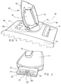
- Figure 1 is a perspective part cut-away view showing an iron in the rest position in a parking dock at one end of an ironing board;
- Figure 2 is a perspective part cut-away view of the tail of the iron depicted in Figure 1;
- Figure 3 is a plan view, partly cut away, of the parking dock depicted in Figure 1;
- Figure 4 is a section view along the line IV-IV of Figure 3, also showing in dashed outline the tail of an iron in the rest position;
- Figure 5 is a fragmentary plan view of another parking dock arrangement;
- Figure 6 is a sectional view through the arrangement of Figure 5, also showing the tail of an iron in the rest position;
- Figure 7 is a side elevation showing an ironing board according to the invention in the trousers press mode with the pressing surfaces closed;
- Figure 8 is a side elevation of the board of Figure 7 with the pressing surfaces open;
- Figure 9 is a side elevation of the board of Figures 7 and 8 in the normal ironing position;
- Figure 10 is a detail of the expanding hinge of the board of Figures 7 to 9;
- Figure 11 is a circuit diagram of an electronic circuit for controlling the temperature of an iron and an ironing board; and
- Figure 12 is a graph showing the performance of the electronic control circuitry.
- Referring first to Figure 1, a
cordless iron 10 including abody portion 11 in which is carried a heater element and a temperature sensor, asole plate 12 and ahandle 13, is shown engaged in the rest position on asupport platform 14 manufactured as an integral part of an ironing board, the heel of the ironing surface of which is shown at 15. The support platform includes afascia plate 10 havingcontrol panels 17 equipped with control buttons and warning lights, and a parking dock comprising aturntable 18. As shown in the rest position and as more fully described with reference to Figures 2-4, the iron is stably held within a recess in the turntable and sloping forwardly at an acute angle to the horizontal, the mouth of the recess being defined by a slot the ends of which haveupstanding formations 19 for imparting additional lateral stability to the iron. - Referring to Figure 2, the tail end of the iron shown in Figure 1 includes a
tongue 20 having a central cut-awayregion 21 in which is carried anearth pin 22. Electrical contacts are provided on either side of the cut-away region; as shown those for providing power to the heater element are designated 23 and those for providing connection to the temperature sensor are designated 24. Thecontacts 23 are slightly higher thancontacts 24, considered in relation to the plane of the tongue. - Referring to Figures 3 and 4, the
turntable 18 of thesupport platform 14 is formed with adiametrical slot 25 which defines the mouth of arecess 26 which includes an undercutregion 27.Electrical contacts 28 are provided in the undercut region, resiliently mounted at an angle to the horizontal onsupport plate 29. The contacts are concealed from view and from touch through theslot 25 byshutters 30 which are slidingly downwardly displaceable in arcuate channels (not shown) against a spring bias, to the position shown in dashed outline at 30a. The opening and closing of the shutters is controlled by anarm 31 centrally mounted in theslot 25 within an open-toppedhousing 32 which effectively divides the slot into two halves. The lower regions of the slot are formed at each end witharcuate shoulders 33. Thearm 31 is electrically connected to the earth conductor of the power cable (not shown) attached to the support platform. - In use, the iron is held approximately vertically with the tail pointing downwards and the tail is offered to the
slot 25 so that theearth pin 22 enters thehousing 32 and engages thearm 31, thereby starting to displace theshutters 30. When thetongue 20 is at the position where it effectively blocks the mouth of the recess, the shutters are sufficiently open to permit the tongue to enter the recess until the lower corners of the tongue engage theshoulders 33. The iron is then allowed to fall forwardly allowing the tongue to perform a rearward arcuate movement, within the recess, guided by theshoulders 33, until the electrical contacts on the tongue engage the fixedcontacts 28, the relative spacing of the contacts ensuring that thepower contacts 23 are in engagement with theircorresponding contacts 28 before thetemperature sensor contacts 24. In Figure 4, the tail of the iron is shown in dashed outline in the rest position with the contacts engaged. In this Figure, theshutters 30 are shown in the closed position, although in practice, with the iron so located, the shutters would be at the position indicated 30a. - An alternative arrangement is shown in Figures 5 and 6. A
turntable housing 51 as part of an ironing board parking dock has aslot 52 formed therein defining the mouth of a recess having sloping front andrear walls rear wall 54 having a greater slope and forming an undercut region for receiving thetail 55 of an iron when interengaged in the rest position, as shown in Figure 6. The slot includes a central open-toppedhousing 56. - Electrical contacts 57-60 (57 and 60 being for power and 58 and 59 for the temperature sensor) within the parking dock are carried on a
T plate 61 which is slidably mounted and biassed byspring 62 to the left, as shown in the drawings. The contacts are aligned with apertures formed inwall 54. Under biassing pressure, the contacts are fully retracted behindwall 54. The leg of theT plate 61 carries alongitudinal operating arm 63 with asloping end 64. This end is below the slit defined by the open-toppedhousing 56. - On offering the tail of the iron to the
slot 52, the earth pin enters the slit defined by the open-topped housing and displaces theoperating arm 63 to the right, thereby bringing the contacts 57-60 forward against the bias and into contact, through the apertures inwall 54, with the electrical contacts on the iron. The contacts 57-60 are themselves individually displaceable against a bias, relative to their mountings, bysprings 57a-60a, to provide substantially the same pressure between each respective pair of contacts. - Referring now to Figures 7, 8 and 9, an ironing
board 71 consists of alower plate assembly 72 having an upperpressing surface 73, and anupper plate assembly 74 thetop surface 75 of which constitutes an ironing surface and thelower surface 76 of which constitutes a pressing surface which cooperates withsurface 73 to form a trousers press, cooperable grippers being provided at the opening ends (one only being illustrated at 77). Asupport platform 14 for a cordless iron is provided at the upper end of the board (in the position shown in Figures 7 and 8) and the plate assemblies are hinged together at their lower ends at 78 by means of a displaceable hinge, in which the hinge pivot may be mounted on the upper plate assembly to be resiliently displaceable away from the lower plate assembly, for example by means of a spring steel mounting bracket attached to the lower plate assembly (see Figure 10), to accommodate trousers, or other items to be pressed, of different thickness while maintaining even pressure along the board between the pressing surfaces. Movement of the plate assemblies is controlled by alever 79 which is hingeably mounted on the rear oflower plate assembly 72. The arms of the lever are in engagement withrollers 80 mounted on the sides of theupper plate assembly 74, so that pivoting thelever 59 forwardly permits the rollers to roll along the arms and the upper plate assembly to swing open to the position shown in Figure 8, while pivoting the lever upwardly causes the upper plate assembly to close to the position shown in Figure 7. The ends of the arms at 81 are deformed to provide a notch to accommodate the rollers and retain the plate assemblies in the closed position against unintentional opening. - As shown in Figures 7 and 8, the supporting legs of the ironing board are open to an intermediate position in which the board is free-standing with the plate assemblies substantially vertical. The board is illustrated in Figure 9 with the legs open to permit the board to be used for ironing. The
leg 82 is hingeably connected to the underside of the lower plate assembly at 83 and is lockably jointed at a knee joint 84 for placing in a storage position (not shown) or for use in the trousers press mode; theleg 85 is pivotally attached toleg 82 at 86 and pivotally and slidably to the underside of the lower plate assembly at 87. The upper ends of the legs are relatively slidable towards and away from each other for the purpose of height adjustment, controlled bylever 88 which releases the legs or locks them at a desired height position. The lower ends of the legs terminate in ground-engaging pads 89 at least one of which may comprise a roller, for facilitating height adjustment. - By "plate assembly" is meant to include body or chassis components, heater elements, electrical connections thereto, padding, surface covering material, grippers for trousers, and the like, as required.
- In Figure 9, a
cordless iron 10 is shown in the rest position on thesupport platform turntable 18. - Figure 10 illustrates an expanding hinge for use at
position 78 in Figure 7. The hinge consists of aspring steel bracket 101 attached to the lower plate assembly at 102 and to the upper plate assembly at 103. The upper andlower plate assemblies points spring steel bracket 105. - Figure 11 illustrates a control circuit for controlling the temperature of an iron and an ironing board from a single setting on a control panel.
- Referring now to Figure 12, the performance of a cordless iron fitted with control circuitry as hereinbefore described is compared with a commercially-available cordless iron controlled by a traditional thermostat. In the graph, the temperatures of 120oC, 160oC and 210oC are recommended by the Home Laundry Consultative Council as being suitable for pressing for example nylons; other man-made textile fabrics and mixtures; and linens and cottons respectively. The prior art iron was tested at all three settings and is seen to fluctuate widely below the set temperatures, (curves 1, 2 and 3 respectively), whereas the inventive iron, which was tested only at the highest setting, was controlled to within a narrow temperature band on either side of the set temperature (curve 4).
Claims (23)
- Ironing apparatus comprising:-
a cordless iron (10) comprising a sole plate (12), a heater element which can be electrically energised and a temperature sensor in thermal contact with the sole plate;
a control module including a support platform (14) for the iron and control circuitry including temperature selection means; and
cooperative interengagement means on the iron and the support;
characterised in that the cooperative interengagement means comprises:
a tongue (20) on the tail end of the iron, the tongue having electrical contacts (22, 24) on an upper surface thereof connected to said heater element; and
an abutment means (54) disposed in a recess in the support platform, wherein the mouth of the recess is formed with an undercut region (26, 27), which undercut region can accommodate the tongue of the iron when the iron is interengaged in a rest position with the support platform, the abutment means comprising electrical contacts (28) which can be connected to a source of electrical power;
the arrangement being such that, in the rest position, the iron is disposed over-centre at a forwardly upwardly sloping angle such that the upper surface of the tongue engages the abutment means of the support platform in the undercut region and the iron is maintained in the rest position under the influence of gravity such that the electrical contacts on the tongue are maintained in contact with the contacts in the abutment means; wherein the supply of electrical power to the heater element is varied by the control circuitry according to the perceived temperature of the sole plate in relation to a temperature set by the temperature selection means. - Ironing apparatus as claimed in claim 1 characterised in that the iron is locatable in or removable from its rest position via a disconnected position, the iron describing a forward pivotal movement with respect to the support platform on moving the iron from the disconnected position to the rest position.
- Ironing apparatus as claimed in claim 1 or claim 2 characterised in that the undercut region has sidewalls which receive the tongue with marginal clearance and/or extend upwardly as raised upstanding formations (19) to enhance the lateral stability of the iron in the rest position.
- Ironing apparatus as claimed in any preceding claim, further including mechanical and/or electrical isolation means to prevent access to live electrical contacts in the undercut region when the iron is removed therefrom.
- Ironing apparatus as claimed in any preceding claim characterised by mechanical shrouds or shutters (30) in the undercut region, said mechanical shrouds or shutters being biased in a closed position to cover the electrical contacts (28) in the abutment means and movable to an open position when the iron is located in its rest position to permit the contacts on the iron to contact the electrical contacts on the abutment means.
- Ironing apparatus as claimed in claim 5 characterised in that on locating the iron in the rest position, said tongue engages a shutter-opening mechanism (31, 32) thereby to move the mechanical shrouds or shutters to the open position, whereby the shutters provide protection until the tongue effectively blocks access to the contacts.
- Ironing apparatus as claimed in any preceding claim characterised in that the electrical contacts in the abutment means are movably mounted and biased in a retracted position in which they are contained in a housing, said electrical contacts being movable against the bias to an extended position in which they protrude from the housing for engagement with contacts on the iron; the electrical contacts in the abutment means being movable from the retracted position to the extended position by the iron on location of the iron in its rest position.
- Ironing apparatus as claimed in any preceding claim, further including means to prevent arcing between the electrical contacts on the iron and support platform on moving the iron between its rest and disconnected positions.
- Ironing apparatus as claimed in any preceding claim characterised in that the contacts on the iron and/or the abutment means are arranged such that on location of the iron in the support platform in the rest position, the contacts are connected in a predetermined sequence to avoid arcing across live contacts.
- Ironing apparatus as claimed in claim 9 characterised by earth contacts (22), live and neutral contacts (23) and temperature sensor contacts (24), the latter forming part of a switching circuit to control the supply of power to the live contact; the arrangement being such that on location of the iron in the support platform in the rest position, the sequence of engagement is firstly the earth contact, secondly the live and neutral contacts, and thirdly the power sensor contacts, whereby the live and neutral contacts are engaged before power is permitted to flow to the live contact.
- Ironing apparatus as claimed in claim 9 or claim 10 characterised in that power switching is perfomed by triacs.
- Ironing apparatus as claimed in any of claims 9 to 11, characterised in that the engagement sequence of the contacts is not completed in less than 10 m.secs.
- Ironing apparatus as claimed in any preceding claim, characterised by the use of feedback control from the temperature sensor thereby to enable a higher-rated element to be used with a greater degree of sensitivity in the control thereof as compared with thermostatically-controlled arrangements.
- Ironing apparatus as claimed in any preceding claim, in which the control module is incorporated in an ironing board (71).
- Ironing apparatus as claimed in claim 14, in which the ironing board includes a heater element, the iron and board heater elements being controlled by the same control circuitry, typically by means of a common microprocessor.
- Ironing apparatus as claimed in claim 15, in which the ironing surface of the board comprises a plate (74) which cooperates with an underlying plate (72) to form a trousers press, the underlying plate being connected to a support system for maintaining the plates above ground level either substantially horizontally disposed for use in an ironing mode or substantially upright disposed for use in a trousers pressing mode.
- Ironing apparatus as claimed in claim 16, in which the plates are hingeably connected together by a displaceable hinge (101) which permits the plates to move apart one from the other in the trousers pressing mode while remaining substantially mutually parallel, thereby to accommodate different thicknesses of items to be pressed while maintaining an even overall pressure thereon.
- Ironing apparatus as claimed in 16 or claim 17, in which the underlying plate has a heater element controlled by the same control circuitry as and to independently-programmable temperatures relative to the heater element in the ironing plate.
- Ironing apparatus as claimed in any preceding claim characterised by an ironing board including an ironing surface and two foldable legs for supporting the ironing surface above ground level in service; wherein each leg is pivotably attached at an upper end of the leg towards a respective end of an underside of the ironing surface and has a foot (89) at a lower end of the leg, the legs being pivoted one to the other at a pivot point (86) intermediate the upper and lower ends of each leg, a first leg (82) having a knee joint means (84) intermediate the upper end of the first leg and the pivot point; the arrangement being such that in an open position, with the knee joint means locked, the legs describe an X configuration in which the ironing surface is supported in a generally horizontal plane above ground level, and with the knee joint means in a broken position the legs can be pivotted one with respect to the other about the pivot point to a fully closed position in which upper and lower parts of the first leg above the pivot point are folded together and the feet of the legs are disposed adjacent one another in juxtaposition with one end of the ironing surface.
- Ironing apparatus as claimed in claim 19 characterised in that, with the knee joint means in the broken position, upper and lower parts of the first leg above the pivot point can be folded together to lower the one end of the ironing surface with respect to the other end in an intermediate position, while maintaining sufficient spacing between the feet of the legs to support the ironing board on the ground in a free-standing position.
- Ironing apparatus as claimed in claim 19 or claim 20 characterised in that the other leg (85) is slidably attached (87) to the underside of the ironing surface to act as a lost-motion linkage on opening or closing of the legs thereby to allow height adjustment of the board.
- Ironing apparatus as claimed in any of claims 19 to 21, in which the ironing board has a heatable ironing surface.
- Ironing apparatus as claimed in any of claims 19 to 22, in which the ironing board includes a separate pressure plate to enable the apparatus to form a trousers press.
Applications Claiming Priority (3)
| Application Number | Priority Date | Filing Date | Title |
|---|---|---|---|
| GB888816089A GB8816089D0 (en) | 1988-07-06 | 1988-07-06 | Pressing apparatus |
| GB8816089 | 1988-07-06 | ||
| PCT/GB1989/000765 WO1990000642A1 (en) | 1988-07-06 | 1989-07-06 | Pressing apparatus |
Publications (2)
| Publication Number | Publication Date |
|---|---|
| EP0423205A1 EP0423205A1 (en) | 1991-04-24 |
| EP0423205B1 true EP0423205B1 (en) | 1995-09-20 |
Family
ID=10639962
Family Applications (1)
| Application Number | Title | Priority Date | Filing Date |
|---|---|---|---|
| EP89908233A Expired - Lifetime EP0423205B1 (en) | 1988-07-06 | 1989-07-06 | Pressing apparatus |
Country Status (8)
| Country | Link |
|---|---|
| US (1) | US5290998A (en) |
| EP (1) | EP0423205B1 (en) |
| JP (1) | JPH04500466A (en) |
| AT (1) | ATE128199T1 (en) |
| AU (1) | AU3877289A (en) |
| DE (1) | DE68924348T2 (en) |
| GB (1) | GB8816089D0 (en) |
| WO (1) | WO1990000642A1 (en) |
Cited By (1)
| Publication number | Priority date | Publication date | Assignee | Title |
|---|---|---|---|---|
| WO2026043365A1 (en) | 2024-08-20 | 2026-02-26 | Brabantia Nederland B.V. | Ironing table |
Families Citing this family (34)
| Publication number | Priority date | Publication date | Assignee | Title |
|---|---|---|---|---|
| GB2238182B (en) * | 1989-10-12 | 1994-05-25 | Gemini Clothescare Ltd | Isolatable contact |
| DE9000832U1 (en) * | 1990-01-25 | 1990-04-12 | Krause-Werk Gmbh & Co Kg, 6320 Alsfeld | Iron rest device |
| DE69113771D1 (en) * | 1990-12-26 | 1995-11-16 | Matsushita Electric Industrial Co Ltd | Ironing device. |
| GB9503250D0 (en) * | 1995-02-20 | 1995-04-12 | Numatic Int Ltd | Improvements in and relating to ironing and pressing apparatus |
| US5844203A (en) * | 1995-10-06 | 1998-12-01 | Black & Decker Inc. | Combined switch actuator and signal light transmitter for an iron |
| US20070266740A9 (en) * | 2000-07-25 | 2007-11-22 | Kendall James W | Vertical laundry module |
| US7624600B2 (en) | 2000-07-25 | 2009-12-01 | Whirlpool Corporation | Modular laundry system with horizontally arranged cabinet module |
| US7628043B2 (en) * | 2000-07-25 | 2009-12-08 | Whirlpool Corporation | Modular laundry system with horizontal modules |
| US7617702B2 (en) | 2000-07-25 | 2009-11-17 | Whirlpool Corporation | Modular laundry system with cabinet module |
| US6402547B1 (en) | 2001-01-18 | 2002-06-11 | Courtesy Products, Llc | Anti-theft ironing system |
| ITPN20010006U1 (en) * | 2001-02-23 | 2002-08-23 | Euro Star Srl | IRONING SUCTION AND / OR BLOWER |
| SG92796A1 (en) * | 2001-04-04 | 2002-11-19 | Koninkl Philips Electronics Nv | Steamer arrangement |
| EP1436455A4 (en) * | 2001-09-12 | 2005-02-09 | Basuki Muljadi | An ironing board |
| US6883257B2 (en) * | 2002-03-15 | 2005-04-26 | Kenneth J. Couch | Ironing board |
| DE10235652B4 (en) * | 2002-08-02 | 2005-12-22 | Carl Freudenberg Kg | Ironing board with ironing board |
| GB2397072B (en) * | 2003-01-10 | 2006-02-22 | George Docker | Trouser Press / Ironing Board |
| GB0403296D0 (en) * | 2004-02-16 | 2004-03-17 | Vale Mill Rochdale Ltd | A support for an iron |
| US20070151303A1 (en) * | 2005-12-30 | 2007-07-05 | Doyle Colleen M | Modular laundry system with work surface having a functional element |
| US20070151306A1 (en) * | 2005-12-30 | 2007-07-05 | Gilboe Kevin J | Modular laundry system with work surface |
| US20060117810A1 (en) * | 2004-10-22 | 2006-06-08 | Kendall James W | Modular Laundry system with segmented work surface |
| US20070151304A1 (en) * | 2005-12-30 | 2007-07-05 | Kendall James W | Modular laundry system with work surface having a functional insert |
| US20070151300A1 (en) * | 2005-12-30 | 2007-07-05 | Sunshine Richard A | Modular laundry system with horizontal module spanning two laundry appliances |
| KR200403190Y1 (en) * | 2005-09-09 | 2005-12-09 | 김성백 | Wireless flatiron custody box |
| US20070151305A1 (en) * | 2005-12-30 | 2007-07-05 | Kendall James W | Modular laundry system with vertical module |
| US7562543B2 (en) * | 2005-12-30 | 2009-07-21 | Whirlpool Corporation | Vertical laundry module with backsplash |
| US20070151309A1 (en) * | 2005-12-30 | 2007-07-05 | Kendall James W | Laundry module for modular laundry system |
| US7587917B2 (en) * | 2005-12-30 | 2009-09-15 | Whirlpool Corporation | Modular laundry system with shelf module |
| US7555856B2 (en) * | 2005-12-30 | 2009-07-07 | Whirlpool Corporation | Ironing station |
| US8033038B2 (en) * | 2005-12-30 | 2011-10-11 | Whirlpool Corporation | Ironing station |
| AU2010316585B2 (en) * | 2009-11-04 | 2013-01-17 | Panasonic Corporation | Cordless iron |
| JP4735754B2 (en) * | 2009-11-04 | 2011-07-27 | パナソニック株式会社 | Cordless iron |
| KR101952052B1 (en) * | 2014-11-22 | 2019-02-25 | 포샨 순더 메이디 일렉트리컬 히팅 어플라이언시스 메뉴팩쳐링 코., 리미티드 | Control method and control sysem for wash aid, and wash aid |
| IT201700019433A1 (en) * | 2017-02-21 | 2018-08-21 | De Longhi Appliances Srl | SUPPORT BASE |
| CN112442826B (en) * | 2019-08-27 | 2023-12-22 | 博西华电器(江苏)有限公司 | Laundry equipment and control method thereof |
Family Cites Families (9)
| Publication number | Priority date | Publication date | Assignee | Title |
|---|---|---|---|---|
| US2339495A (en) * | 1942-10-02 | 1944-01-18 | Carl R Mcmann | Electrical appliance switch |
| NL72719C (en) * | 1946-11-07 | |||
| GB1399827A (en) * | 1971-10-01 | 1975-07-02 | British Domestic Appliances | Electric smoothing irons and to stands therefor |
| US3745676A (en) * | 1972-08-04 | 1973-07-17 | J Dikoff | Cordless iron apparatus |
| EP0328727B1 (en) * | 1983-03-28 | 1993-11-10 | Numatic International Limited | Laundry ironing or pressing apparatus |
| DE3486244T2 (en) * | 1983-03-28 | 1995-02-02 | Numatic Int Ltd | Device for ironing or pressing laundry. |
| US4827104A (en) * | 1986-10-16 | 1989-05-02 | Dart Industries Inc. | Phototransistor relay electronic temperature control for cordless irons |
| EP0268722A1 (en) * | 1986-11-21 | 1988-06-01 | ELETTRODOMUS S.p.A. | An electric resistance iron of the so-called cordless type |
| CH678866A5 (en) * | 1987-02-10 | 1991-11-15 | Jura Elektroapparate Fab |
-
1988
- 1988-07-06 GB GB888816089A patent/GB8816089D0/en active Pending
-
1989
- 1989-07-06 WO PCT/GB1989/000765 patent/WO1990000642A1/en not_active Ceased
- 1989-07-06 EP EP89908233A patent/EP0423205B1/en not_active Expired - Lifetime
- 1989-07-06 AT AT89908233T patent/ATE128199T1/en not_active IP Right Cessation
- 1989-07-06 US US07/663,895 patent/US5290998A/en not_active Expired - Fee Related
- 1989-07-06 AU AU38772/89A patent/AU3877289A/en not_active Abandoned
- 1989-07-06 JP JP1507872A patent/JPH04500466A/en active Pending
- 1989-07-06 DE DE68924348T patent/DE68924348T2/en not_active Expired - Fee Related
Cited By (2)
| Publication number | Priority date | Publication date | Assignee | Title |
|---|---|---|---|---|
| WO2026043365A1 (en) | 2024-08-20 | 2026-02-26 | Brabantia Nederland B.V. | Ironing table |
| NL2038465B1 (en) | 2024-08-20 | 2026-03-02 | Brabantia Nederland Bv | Ironing table |
Also Published As
| Publication number | Publication date |
|---|---|
| AU3877289A (en) | 1990-02-05 |
| EP0423205A1 (en) | 1991-04-24 |
| ATE128199T1 (en) | 1995-10-15 |
| DE68924348T2 (en) | 1996-05-09 |
| JPH04500466A (en) | 1992-01-30 |
| DE68924348D1 (en) | 1995-10-26 |
| WO1990000642A1 (en) | 1990-01-25 |
| US5290998A (en) | 1994-03-01 |
| GB8816089D0 (en) | 1988-08-10 |
Similar Documents
| Publication | Publication Date | Title |
|---|---|---|
| US5290998A (en) | Cordless iron and electrically heated ironing board combination | |
| US7406783B2 (en) | Self lifting iron | |
| EP0311003B1 (en) | Cordless iron assembly | |
| CA2008647C (en) | Electric kettle | |
| US7121024B1 (en) | Creaser steam iron | |
| US6307182B1 (en) | Electric appliance having a proximity sensor | |
| US20060191299A1 (en) | Garment steamer | |
| EP0126530B1 (en) | Laundry ironing or pressing apparatus | |
| WO1988003579A1 (en) | Ironing apparatus | |
| GB2297982A (en) | Ironing apparatus | |
| KR900008497B1 (en) | Electric kettle consisting of a vessel supported on a base-plate wich is connected electrically to the power supply system | |
| US2527775A (en) | Electric iron with signaling means | |
| US2149251A (en) | Electric flatiron with self-acting safety device | |
| US3366776A (en) | Holder for an electrically heated cooking vessel | |
| JPH01314600A (en) | Power supply apparatus for codeless heat accumulation iron | |
| EP0328727B1 (en) | Laundry ironing or pressing apparatus | |
| GB2318502A (en) | Electric toasting machine with timing circuit | |
| US5730396A (en) | Cord guide for appliance caddy | |
| US2511309A (en) | Electric iron and iron elevating means | |
| JPS603840Y2 (en) | Cordless ironing device | |
| JP3451610B2 (en) | Ironing equipment | |
| US5790009A (en) | Thermostat reset with additional electrical switch | |
| KR101071496B1 (en) | A apparatus for removing rumple of clothes | |
| RU2074917C1 (en) | Hand-held electric iron | |
| US1983974A (en) | Pressing machine |
Legal Events
| Date | Code | Title | Description |
|---|---|---|---|
| PUAI | Public reference made under article 153(3) epc to a published international application that has entered the european phase |
Free format text: ORIGINAL CODE: 0009012 |
|
| 17P | Request for examination filed |
Effective date: 19910102 |
|
| AK | Designated contracting states |
Kind code of ref document: A1 Designated state(s): AT BE CH DE FR GB IT LI LU NL SE |
|
| 17Q | First examination report despatched |
Effective date: 19921019 |
|
| RAP1 | Party data changed (applicant data changed or rights of an application transferred) |
Owner name: NUMATIC INTERNATIONAL LIMITED |
|
| GRAA | (expected) grant |
Free format text: ORIGINAL CODE: 0009210 |
|
| AK | Designated contracting states |
Kind code of ref document: B1 Designated state(s): AT BE CH DE FR GB IT LI LU NL SE |
|
| REF | Corresponds to: |
Ref document number: 128199 Country of ref document: AT Date of ref document: 19951015 Kind code of ref document: T |
|
| ITF | It: translation for a ep patent filed | ||
| ET | Fr: translation filed | ||
| REF | Corresponds to: |
Ref document number: 68924348 Country of ref document: DE Date of ref document: 19951026 |
|
| PLBE | No opposition filed within time limit |
Free format text: ORIGINAL CODE: 0009261 |
|
| STAA | Information on the status of an ep patent application or granted ep patent |
Free format text: STATUS: NO OPPOSITION FILED WITHIN TIME LIMIT |
|
| 26N | No opposition filed | ||
| PGFP | Annual fee paid to national office [announced via postgrant information from national office to epo] |
Ref country code: GB Payment date: 20010628 Year of fee payment: 13 |
|
| PGFP | Annual fee paid to national office [announced via postgrant information from national office to epo] |
Ref country code: SE Payment date: 20010709 Year of fee payment: 13 |
|
| PGFP | Annual fee paid to national office [announced via postgrant information from national office to epo] |
Ref country code: BE Payment date: 20010718 Year of fee payment: 13 |
|
| PGFP | Annual fee paid to national office [announced via postgrant information from national office to epo] |
Ref country code: LU Payment date: 20010724 Year of fee payment: 13 |
|
| PGFP | Annual fee paid to national office [announced via postgrant information from national office to epo] |
Ref country code: AT Payment date: 20010725 Year of fee payment: 13 |
|
| PGFP | Annual fee paid to national office [announced via postgrant information from national office to epo] |
Ref country code: FR Payment date: 20010727 Year of fee payment: 13 Ref country code: CH Payment date: 20010727 Year of fee payment: 13 |
|
| PGFP | Annual fee paid to national office [announced via postgrant information from national office to epo] |
Ref country code: NL Payment date: 20010731 Year of fee payment: 13 |
|
| PGFP | Annual fee paid to national office [announced via postgrant information from national office to epo] |
Ref country code: DE Payment date: 20010830 Year of fee payment: 13 |
|
| REG | Reference to a national code |
Ref country code: GB Ref legal event code: IF02 |
|
| PG25 | Lapsed in a contracting state [announced via postgrant information from national office to epo] |
Ref country code: LU Free format text: LAPSE BECAUSE OF NON-PAYMENT OF DUE FEES Effective date: 20020706 Ref country code: GB Free format text: LAPSE BECAUSE OF NON-PAYMENT OF DUE FEES Effective date: 20020706 Ref country code: AT Free format text: LAPSE BECAUSE OF NON-PAYMENT OF DUE FEES Effective date: 20020706 |
|
| PG25 | Lapsed in a contracting state [announced via postgrant information from national office to epo] |
Ref country code: SE Free format text: LAPSE BECAUSE OF NON-PAYMENT OF DUE FEES Effective date: 20020707 |
|
| PG25 | Lapsed in a contracting state [announced via postgrant information from national office to epo] |
Ref country code: LI Free format text: LAPSE BECAUSE OF NON-PAYMENT OF DUE FEES Effective date: 20020731 Ref country code: CH Free format text: LAPSE BECAUSE OF NON-PAYMENT OF DUE FEES Effective date: 20020731 Ref country code: BE Free format text: LAPSE BECAUSE OF NON-PAYMENT OF DUE FEES Effective date: 20020731 |
|
| BERE | Be: lapsed |
Owner name: *NUMATIC INTERNATIONAL LTD Effective date: 20020731 |
|
| PG25 | Lapsed in a contracting state [announced via postgrant information from national office to epo] |
Ref country code: NL Free format text: LAPSE BECAUSE OF NON-PAYMENT OF DUE FEES Effective date: 20030201 Ref country code: DE Free format text: LAPSE BECAUSE OF NON-PAYMENT OF DUE FEES Effective date: 20030201 |
|
| GBPC | Gb: european patent ceased through non-payment of renewal fee |
Effective date: 20020706 |
|
| EUG | Se: european patent has lapsed | ||
| REG | Reference to a national code |
Ref country code: CH Ref legal event code: PL |
|
| PG25 | Lapsed in a contracting state [announced via postgrant information from national office to epo] |
Ref country code: FR Free format text: LAPSE BECAUSE OF NON-PAYMENT OF DUE FEES Effective date: 20030331 |
|
| NLV4 | Nl: lapsed or anulled due to non-payment of the annual fee |
Effective date: 20030201 |
|
| REG | Reference to a national code |
Ref country code: FR Ref legal event code: ST |
|
| PG25 | Lapsed in a contracting state [announced via postgrant information from national office to epo] |
Ref country code: IT Free format text: LAPSE BECAUSE OF NON-PAYMENT OF DUE FEES;WARNING: LAPSES OF ITALIAN PATENTS WITH EFFECTIVE DATE BEFORE 2007 MAY HAVE OCCURRED AT ANY TIME BEFORE 2007. THE CORRECT EFFECTIVE DATE MAY BE DIFFERENT FROM THE ONE RECORDED. Effective date: 20050706 |