EP0422870A2 - Méthode pour l'impression de plusieurs tons - Google Patents
Méthode pour l'impression de plusieurs tons Download PDFInfo
- Publication number
- EP0422870A2 EP0422870A2 EP90311001A EP90311001A EP0422870A2 EP 0422870 A2 EP0422870 A2 EP 0422870A2 EP 90311001 A EP90311001 A EP 90311001A EP 90311001 A EP90311001 A EP 90311001A EP 0422870 A2 EP0422870 A2 EP 0422870A2
- Authority
- EP
- European Patent Office
- Prior art keywords
- channels
- channel
- printing
- ink
- pulses
- Prior art date
- Legal status (The legal status is an assumption and is not a legal conclusion. Google has not performed a legal analysis and makes no representation as to the accuracy of the status listed.)
- Granted
Links
Images


Classifications
-
- H—ELECTRICITY
- H04—ELECTRIC COMMUNICATION TECHNIQUE
- H04N—PICTORIAL COMMUNICATION, e.g. TELEVISION
- H04N1/00—Scanning, transmission or reproduction of documents or the like, e.g. facsimile transmission; Details thereof
- H04N1/40—Picture signal circuits
- H04N1/40025—Circuits exciting or modulating particular heads for reproducing continuous tone value scales
- H04N1/40031—Circuits exciting or modulating particular heads for reproducing continuous tone value scales for a plurality of reproducing elements simultaneously
-
- B—PERFORMING OPERATIONS; TRANSPORTING
- B41—PRINTING; LINING MACHINES; TYPEWRITERS; STAMPS
- B41J—TYPEWRITERS; SELECTIVE PRINTING MECHANISMS, i.e. MECHANISMS PRINTING OTHERWISE THAN FROM A FORME; CORRECTION OF TYPOGRAPHICAL ERRORS
- B41J2/00—Typewriters or selective printing mechanisms characterised by the printing or marking process for which they are designed
- B41J2/005—Typewriters or selective printing mechanisms characterised by the printing or marking process for which they are designed characterised by bringing liquid or particles selectively into contact with a printing material
- B41J2/01—Ink jet
- B41J2/135—Nozzles
- B41J2/14—Structure thereof only for on-demand ink jet heads
- B41J2/14201—Structure of print heads with piezoelectric elements
- B41J2/14209—Structure of print heads with piezoelectric elements of finger type, chamber walls consisting integrally of piezoelectric material
-
- B—PERFORMING OPERATIONS; TRANSPORTING
- B41—PRINTING; LINING MACHINES; TYPEWRITERS; STAMPS
- B41J—TYPEWRITERS; SELECTIVE PRINTING MECHANISMS, i.e. MECHANISMS PRINTING OTHERWISE THAN FROM A FORME; CORRECTION OF TYPOGRAPHICAL ERRORS
- B41J2/00—Typewriters or selective printing mechanisms characterised by the printing or marking process for which they are designed
- B41J2/005—Typewriters or selective printing mechanisms characterised by the printing or marking process for which they are designed characterised by bringing liquid or particles selectively into contact with a printing material
- B41J2/01—Ink jet
- B41J2/21—Ink jet for multi-colour printing
- B41J2/2121—Ink jet for multi-colour printing characterised by dot size, e.g. combinations of printed dots of different diameter
- B41J2/2128—Ink jet for multi-colour printing characterised by dot size, e.g. combinations of printed dots of different diameter by means of energy modulation
Definitions
- This invention relates to multi-tone printing employing drop-on-demand printing apparatus. More particularly the invention relates to such apparatus for printing droplets on printing element areas on a substrate which is movable relatively to said apparatus and comprises an array of parallel, uniformly spaced channels provided with respective droplet ejection nozzles, a liquid supply means common to said channels and electrically operated means for applying pulses of energy to droplet liquid in said channels to effect droplet ejection there from.
- the types of printing apparatus disclosed in the references quoted are of the kind in which energy pulses are imparted to droplet liquid by displacement of wall portions of the respective droplet liquid channels.
- the present invention is, however, also applicable to drop-on-demand printing apparatus having an array of channels such as is known from US-A 3,179,042, GB-A-2,007,162 and GB-A-2,106,039 in which droplet ejection is effected from the channels by applying a pulse of, thermal energy to droplet liquid therein.
- the second and subsequent drop volumes are each connected to the preceding drop volume emitted and the drop volumes join together to form an enlarged droplet which is deposited on the print medium.
- the known method of droplet ejection severely limits, to only a few, the number of droplet volumes which can be added to the droplet volume initially ejected from any particular channel. This number diminishes rapidly with increase of channel density. It follows that the number of greyscale gradations which can be achieved by this known method is limited in the achievable number of different drop volumes which can be deposited at a pixel of the printed image.
- an object of the present invention to provide an improved method of greyscale printing which employs a drop-on-demand printer having an array of parallel channels which enables printing of a substantially greater number of greyscale gradations than has been achievable hitherto.
- the present invention consists in the method of multi-tone printing employing drop-on-demand printing apparatus for depositing ink droplets on printing element areas of a substrate which is movable relatively to said apparatus, comprising an array of parallel uniformly spaced channels provided with respective droplet ejection nozzles, an ink supply common to said channels, and electrically actuable means for applying pulses of energy to ink in said channels to effect droplet ejection therefrom, characterised by choosing the length of said channels and the dimensions and location of said nozzles to afford channels of high longitudinal acoustic resonant frequency and applying in successive periods to ink in respective numbers of channels selected for actuation in each of said periods, by said electrically actuable means, respective sequences of pulses of energy of amplitude and frequency to cause droplet ejection from the selected channels at or near the resonant frequency of the channels, each sequence of pulses containing a number of pulses to eject a corresponding number of discrete droplets, said number being determined by the tone of printing required to be
- said electrically actuable means effect droplet ejection from said channels by displacement of respective side wall portions thereof.
- said electrically actuable means effect droplet ejection from said channels by causing thermal stress in the ink therein.
- droplet deposition from each channel takes place over a length of said substrate which is within a printing element area traversed during printing by the channels.
- droplet deposition on said substrate from each channel takes place over approximately two thirds of the pitch of the printing element areas in the direction of relative motion of the apparatus and substrate and is symmetrically disposed with respect thereto.
- the pitch in the direction of relative motion between the subs trate and the printing apparatus of the printing element areas is suitably made equal to the ink channel pitch.
- the method of the invention is practised with a printhead comprising a body of piezo-electric material in which said channels are formed and opposed channel dividing side walls of each of said channels have respective piezo-electric portions which are displaceable in shear mode by operation of said electrically actuable means to effect droplet ejection from said channel.
- the channels are divided into a plurality of groups of interleaved channels and droplet ejection is enabled in each group simultaneously from selected channels, the channels selected in such group being actuated in successive phases of the frequency of the applied energy pulses.
- the channels are arranged in two groups and selected channels of said two groups are enabled for droplet ejection at intervals of half a cycle of the frequency of pulses applied by said electrically actuable means to the channels selected for droplet ejection.
- the method of the invention consists in arranging the array of channels in a set or sets of four rows of channels, the rows of each set being respectively supplied with black ink and ink of the three primary colours and disposing the rows of each set for printing a row of printing element areas extending transversely to the direction of relative motion of the array and the substrate so that each area printed can be printed in black ink or ink of one of the three primary colours.
- the invention is not however restricted to array apparatus.
- the invention also consists in the method of multi-tone printing employing drop-on-demand printing apparatus for depositing liquid droplets on a printing element area of a substrate, comprising a liquid channel provided with an ejection nozzle, droplet liquid supply means connected with said channel and electrically actuable means for applying pulses of energy to liquid in said channel to effect droplet ejection therefrom, characterised by choosing the channel dimensions and the dimensions and location of the nozzle so that said channel has a high longitudinal acoustic resonant frequency and applying to liquid in said channel by said electrically actuable means, one or a sequence of pulses of energy of amplitude and frequency to cause droplet ejection from the nozzle of said channel at or near the resonant frequency of said channel thereby to eject a number of droplets from said nozzle corresponding to the number of pulses applied to the liquid in said channel, said number of pulses being determined by the tone of printing required to be effected in said printing element area.
- colour printing can be effected by providing four channels respectively supplied with black ink and ink of the three primary colours, the nozzles of said channels being arranged so that each printing element area can be printed with any one of said inks.
- the invention further consists in a multi-channel array, electrically pulsed droplet deposition apparatus.
- a multiplicity of parallel channels comprising a multiplicity of parallel channels, mutually spaced in an array direction normal to the length of the channels, said channels having respective side walls which extend in the lengthwise direction of the channels, and in a direction which is both normal to said lengthwise direction and normal to the array direction, respective nozzles communicating with said channels for ejection of droplets of liquid, connection means for connecting said channels to a source of droplet deposition liquid and electrically actuable means located in relation to said channels to effect, upon actuation of any selected channel, application of pulses of energy to droplet liquid in said selected channel to effect droplet ejection from the nozzle communicating therewith, characterised in that said channels have length dimensions and nozzle dimensions and locations to afford channels of high longitudinal acoustic resonant frequency and said electrically actuable means are adapted to apply in successive periods to droplet liquid in respective numbers of channels selected for actuation in each of said periods respective sequences of
- said channels include respective displaceable side wall portions and said electrically actuable means are adapted to effect displacement of said side wall portions to impart said energy pulses to droplet liquid in the channels.
- Said channels are advantageously arranged in a plurality of groups of interleaved channels, the channels of the respective groups being disposed in repeated sequences and said electrically actuable means are adapted to cause selected channels of each group to be enabled for actuation simultaneously and to effect enabling of the groups of channels in successive intervals of duration to allow ejection of several drops from the enabled channels.
- the channel length, channel nozzle diameter and channel density of the apparatus lie respectively in the range 10 to 1mm, 20 to 10 ⁇ m and 2 to 12 per mm.
- the said dimensions are chosen to provide channel resonant frequencies of above 25 KHz.
- the chosen resonant frequency is in the range 50 KHz to 250 KHz.
- the invention further consists in an electrically pulsed droplet deposition apparatus, comprising a liquid channel having an ink ejection nozzle, droplet liquid supply means connected with said channel and electrically actuable means for supplying pulses of energy to liquid in said channel to effect droplet ejection therefrom, characterised in that the dimensions of the channel and the dimensions and location of the nozzle are adapted to provide the channel with a high longitudinal acoustic resonant frequency so that application to ink in the channel of one or a sequence of pulses of energy of amplitude and frequency at or near the resonant frequency of the channel causes ejection of droplets corresponding in number to said applied pulses whereby the number of droplets deposited from the nozzle can be selected to correspond with a desired tone of printing.
- translating means are provided for moving the channel or group of channels relatively to a substrate to be printed.
- the invention consists in a drop-on-demand printing apparatus for depositing ink droplets on a substrate comprising an array of printing channels provided with respective nozzles for depositing ink droplets on respective printing element areas of said substrate, ink supply means connected with said channels and electrically actuable means for applying pulses of energy to ink in said channels to effect droplet ejection therefrom, characterised in that the length of the channels and the location and dimensions of the nozzles provide the channels with high longitudinal resonant frequency so that application to ink in the channels of a pulse or sequence of pulses of energy of amplitude and frequency to cause droplet ejection from the channels at or near the resonant frequency of the channels causes ejection of droplets from the channels corresponding in number to the number of energy pulses applied to the ink therein whereby the number of droplets deposited from each nozzle can be selected to correspond with a desired tone of printing and effect printing with the substrate stationary relatively to the apparatus.
- the method of the invention can be performed by a drop-on-demand ink jet printing apparatus comprising an array, preferably a high density array, of parallel uniformly spaced channels provided with respective droplet ejection nozzles, an ink supply common to said channels and electrically actuable means for displacing respective piezo-electric side wall portions of said channels to effect droplet ejection from the channels.
- a drop-on-demand ink jet printing apparatus comprising an array, preferably a high density array, of parallel uniformly spaced channels provided with respective droplet ejection nozzles, an ink supply common to said channels and electrically actuable means for displacing respective piezo-electric side wall portions of said channels to effect droplet ejection from the channels.
- each of the channel dividing side walls is shared between the channels which it separates so that in a first of successive phases of operation it can be deflected together with the facing wall of one of the channels which it separates to eject a droplet from said one of the channels whilst in a succeeding phase of the operation the said channel dividing wall together with the facing side wall of the other of the channels which it separates can be deflected to eject a droplet from said other of the channels.
- the channel densities of such printheads can be from 2 to 16 per mm.
- the operation of this form of printhead has been limited to the application of a voltage waveform pulse which acts to eject a single drop of ink from the channel to which the pulse is applied.
- the present invention calls for droplet ejection from the channels at high frequency at or near the longitudinal acoustic resonant frequency of the channels. Accordingly the channel length and nozzle dimensions have to be chosen to that end.
- Printheads of the kind described can also be employed according to this invention as greyscale and, therefore, colour printers.
- An acceptable range of resolution of printing element areas or pixels on a paper subs trate for a printhead as described in our co-pending European patent application referred to would be 6 to 12 per mm.
- a variable number of droplets in the range 1 to 64 is made available as hereinafter described.
- Typical values of ink drop parameters at each channel nozzle and on the paper substrate area are as follows:- Resolution of Printhead Pitch of Nozzles Full 64 Droplet Volume Single Drop Volume Single Droplet Diameter Droplet Frequency -/mm ⁇ m pl pl ⁇ m kHz 12 83 33 0.51 10 180 6 167 130 2.04 15.7 90
- the full size drop volume which forms a pool of 64 single ejected small droplets on the paper substrate is chosen to form contiguous dots at full tone.
- Figure 1 shows the effect of depositing a variable number of ink droplets between 1 and 64 in successive pixels as the paper moves past the nozzle.
- the maximum droplet production frequency is sufficient to generate 100 droplets per pixel, so that if 64 droplets are generated, these are deposited in a line occupying approximately 2/3 of the pixel pitch "p".
- p the pixel pitch
- the spacing between droplets deposited longitudinally in each pixel, for twelve pixels per mm, is 0.83 ⁇ m and for six pixels per mm is 1.67 ⁇ m.
- the nozzle pitch is equal to the pixel pitch.
- the spacing in the lines in which they are deposited of the small droplets is small compared with the diameter of the small droplets, 0.83 ⁇ m compared with 10 ⁇ m for twelve pixels per mm and 1. 67 ⁇ m compared with 15.7 ⁇ m for six pixels per mm.
- the period during which a droplet sequence is ejected, i.e. for 12 pixels per mm and for six pixels per mm is short compared with the time, of a few milliseconds, that ink takes to be absorbed into the paper substrate.
- the printhead 100 comprises a sheet of piezo-electric material poled in a direction normal thereto and formed with parallel channels 104 at a density of two or more per millimetre having channel dividing side walls 106.
- the channels 104 are each lined with a metal electrode layer (not shown).
- the channels which are arranged in three groups of interleaved channels with the channels of the groups disposed successively, are actuated in shear mode by applying an electric potential difference between the electrode layer of an actuated channel and the electrode layers of the channels on either side of the actuated channel.
- the potential difference applied is a signal of frequency at or near the longitudinal acoustic resonant frequency of the channels and is applied for the duration of a number of pulses of the signal corresponding to the number of droplets which it is desired to eject from the actuated channel.
- the channels are supplied with printing liquid from a common supply duct 108 connected with each channel at the end thereof opposite that at which is located a nozzle plate 107 formed with respective nozzles 109 which terminate the channels.
- the nozzles of each group are co-linearly disposed transversely to the direction of movement of a substrate (111), e.g. paper and the groups of nozzles are spaced in the direction of substrate movement.
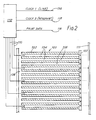
- FIG. 2 illustrates circuitry for operating channels of one of the three channel groups. This comprises connections 110 to the electrodes of the channels of the group, like connections (not shown) being made to the electrodes of each of the channels of the other two groups.
- connections 110 lead to the channels 104 from a processor 112 which is supplied with clock pulses from a conductor 114, the pulses on which in sequence enable the connections 110 to the respective groups of channels.
- a further clock line conductor 116 provides the processor with clock pulses at a frequency at or near that of the longitudinal acoustic resonant frequency of the channels.
- Print data in the form of multi-bit words (a) instructs the processor as to which channels of the group of channels which are enabled by the pulse on the conductor 114 are to be selected for actuation, (b) activates the selected channels each with a number from 1 to 64 of pulses at the frequency supplied by way of the conductor 116, and (c) locates the pulses activating the selected channels centrally in the period during which the connections 110 of the group are enabled.
- the frequency of pulses supplied by way of the conductor 114 is one-hundredth that of the pulse frequency supplied by way of conductor 116 and the period of the pulses at the frequency supplied via conductor 116 is equal to the time taken for successive pixels on the substrate to pass the channel nozzles. It will be apparent that clock line conductor 114 is not strictly necessary since the processor can be arranged to afford pulses, divided from the pulses supplied by way of conductor 116, for enabling the connections 110 to the channels of each group at a frequency of one-hundredth that of the frequency supplied by way of the conductor 116.
- an actuated channel is separated from the next nearest actuated channel by at least two inactive channels. Because of this crosstalk between channels is reduced and risk of spurious droplet ejection from inactive channels adjacent actuated channels is avoided.
- the spacing, referred to above, of channel nozzles of each group in the direction of printing subs trate movement compensates for the time interval between the actuation of the selected channels of the groups so that printed spots deposited at the pixels of each row thereof transverse to substrate movement appear substantially collinear
- Figure 3 illustrates diagrammatically an alternative manner in which the droplets are ejected from the nozzles of ten channels of a segment of a high density array printhead of the type described in our co-pending European patent application No. 88300146.3, for example, with respect to Figure 2(a) to (d) thereof.
- the channels here are arranged in two groups of interleaved odd and even numbered channels.
- the selected channels of one group are activated by applying a resonant waveform in alternating phase with the channels of the other group.
- drops are ejected from channels of the two groups in numbers depending on the number of waveforms applied in alternating phases of the resonant waveform as the dividing walls pressurise channels of the interleved groups alternately.
- the densities at pixels opposite the ten channel nozzles are for channels 1 to 10 respectively 64, 64, 60, 55, 40, 32, 17, 8, 5 and 1 droplets.
- a single pixel in the direction of relative motion between the printhead and paper subs trate is traversed in a period which is equal to the period of 100 cycles of the resonant frequency of the channels, i.e. for the frequencies 180 kHz and 90 KHz of the table set out above of typical values, respectively, 0.55 and 1.11 msecs. These times are those which it would take to emit 100 droplets from each channel.
- the dots in the drawing represent droplets a maximum of 64 of which are deposited from any particular channel per pixel and the actuation of the channels is preferably arranged so that the droplets deposited from any particular channel are symmetrically deposited with respect to the pixel being printed, that is to say the centre of the pixel is traversed after the elapse of fifty of the hundred cycles allocated to that pixel
- the lateral pitch of the channel nozzles is made equal to the longitudinal pitch of the pixels traversed by each nozzle
- each pixel period i.e. the period in which, if supplied to the electrodes of any particular channel, the applied voltage pulses would generate 100 droplets
- the number of droplets from each channel would be between one and sixtyfour in the numbers stated earlier.
- the droplets are ejected from the selected odd numbered channels as a result of actuation of the channels during the positive parts of the cycles and the selected even numbered channels are actuated one half cycle following, that is to say, out of phase with, activation of the selected odd numbered channels.
- Channel No. 1 thus deposits drops every cycle from cycle 19 to cycle 82, channel No. 2 every half cycle from cycle 19 1/2 to 82 1/2 , channel No. 3 every cycle from cycle 21 to cycle 80, channel No. 4 every half cycle from cycle 23 1/2 to cycle 79 1/2 , channel 5 every cycle from cycle 31 to cycle 70, channel 6 every half cycle from cycle 35 1/2 to cycle 66 1/2 , channel 7 every cycle from cycle 42 to cycle 58, channel 8 every half cycle from cycle 47 1/2 to 54 1/2 , channel 9 every half cycle from cycle 49 to cycle 53, and channel 10 at half cycle 50 1/2 .
- the frequency of operation which may be in the range 25 to 250 KHz, and the small size of nozzle employed tend to ensure that the drop sequences emitted from the nozzles comprise separate drops, there may be an inclination for the first few drops of a sequence to merge. This can be avoided by applying initial sub-threshold resonant waveforms or by increasing the energy content of the first few pulses applied by the electrically operated means of the printhead to the channel selected for droplet ejection.
- the embodiment of Figure 3 represents a higher speed (x3) embodiment of printhead. However it is limited in the range of patterns it will print, to a maximum spatial frequency. It will print "white, black, white” but not “black, white, black” across the row of channels. Differently expressed, the embodiment of Figure 3 with a density of nozzles at 12 per mm. prints any pattern at spatial frequencies of and below 4 lines per mm: but is restricted in the patterns that can be printed at spatial frequency of 6 lines per mm. The embodiment of Figure 2 does not have such a restriction but operates more slowly.
- the pulses of energy applied to the printing liquid in the channels of the array are obtained by the use of electrically displaceable channel side walls. Fluid resonance in the channels of the printhead can however be accomplished in other ways.
- thermal energy pulses can be imparted to liquid in the channels for droplet ejection.
- the pulses would be applied at or near the natural longitudinal resonant frequency of the channels, the length and channel dimensions of which would be made such as to provide the requisite high resonant frequency above 25KHz.
- the energy coupling to the liquid in the channels involves thermal expansion and contraction of the liquid and, above a specific energy threshold, the energy input to the channel liquid would cause bubble nucleation and collapse.
- actuation which might possibly be considered involve a fluid which swells in the presence of a field or which becomes solid and thus inhibits displacement in the presence of a field, the resonant energy being applied externally.
Applications Claiming Priority (4)
| Application Number | Priority Date | Filing Date | Title |
|---|---|---|---|
| GB8922821 | 1989-10-10 | ||
| GB898922821A GB8922821D0 (en) | 1989-10-10 | 1989-10-10 | Method of multi-tone printing |
| GB9001493 | 1990-01-23 | ||
| GB909001493A GB9001493D0 (en) | 1990-01-23 | 1990-01-23 | Method of multi-tone printing |
Publications (3)
| Publication Number | Publication Date |
|---|---|
| EP0422870A2 true EP0422870A2 (fr) | 1991-04-17 |
| EP0422870A3 EP0422870A3 (en) | 1991-07-03 |
| EP0422870B1 EP0422870B1 (fr) | 1995-01-11 |
Family
ID=26296027
Family Applications (1)
| Application Number | Title | Priority Date | Filing Date |
|---|---|---|---|
| EP90311001A Expired - Lifetime EP0422870B1 (fr) | 1989-10-10 | 1990-10-08 | Méthode pour l'impression de plusieurs tons |
Country Status (8)
| Country | Link |
|---|---|
| US (1) | US5361084A (fr) |
| EP (1) | EP0422870B1 (fr) |
| JP (2) | JP2800065B2 (fr) |
| AT (1) | ATE116908T1 (fr) |
| CA (1) | CA2027161C (fr) |
| DE (1) | DE69015953T2 (fr) |
| DK (1) | DK0422870T3 (fr) |
| ES (1) | ES2066149T3 (fr) |
Cited By (15)
| Publication number | Priority date | Publication date | Assignee | Title |
|---|---|---|---|---|
| EP0517543A3 (fr) * | 1991-06-07 | 1992-12-23 | Canon Kabushiki Kaisha | Méthode d'enregistrement par jet d'encre |
| US5394181A (en) * | 1992-07-29 | 1995-02-28 | Eastman Kodak Company | Air bubble removal in a drop on demand ink jet print head |
| WO1996010488A1 (fr) * | 1994-09-30 | 1996-04-11 | Xaar Limited | Procede d'impression multi-teintes |
| EP0827838A2 (fr) * | 1996-09-09 | 1998-03-11 | Seiko Epson Corporation | Imprimante à jet d'encre et méthode d'impression à jet d'encre |
| WO1998051504A1 (fr) | 1997-05-15 | 1998-11-19 | Xaar Technology Limited | Fonctionnement d'un appareil a depot de gouttelettes |
| WO1999012738A1 (fr) * | 1997-09-08 | 1999-03-18 | Xaar Technology Limited | Impression multi-teintes par jet d'encre goutte a la demande |
| WO1999041084A1 (fr) | 1998-02-12 | 1999-08-19 | Xaar Technology Limited | Procede de mise en service d'un dispositif servant a deposer une gouttelette |
| EP0953451A3 (fr) * | 1998-04-28 | 1999-11-10 | Xerox Corporation | Procédé d'impression avec décalage de phase d'impression pour réducir la charge de pointe de consommation |
| WO2000011971A2 (fr) | 1998-08-26 | 2000-03-09 | Fuisz Technologies Ltd. | Boisson et composition pour boisson a teneur renforcee en vitamines et en fibres |
| EP1213145A2 (fr) | 1996-03-15 | 2002-06-12 | Xaar Technology Limited | Fonctionnement d'un appareil de dépot de gouttelettes |
| US6655798B2 (en) | 1998-11-20 | 2003-12-02 | Xaar Technology Limited | Methods of inkjet printing |
| WO2010055344A1 (fr) | 2008-11-12 | 2010-05-20 | Xaar Technology Limited | Procédé et appareil pour dépôt de gouttelettes |
| WO2010055345A1 (fr) | 2008-11-12 | 2010-05-20 | Xaar Technology Limited | Procédé et appareil pour dépôt de gouttelettes |
| US7722157B2 (en) | 2002-08-30 | 2010-05-25 | Xaar Technology Limited | Ink jet printing method and printer |
| US10889110B2 (en) | 2017-06-06 | 2021-01-12 | Xaar Technology Limited | Method and apparatus for droplet deposition |
Families Citing this family (34)
| Publication number | Priority date | Publication date | Assignee | Title |
|---|---|---|---|---|
| JP3339724B2 (ja) * | 1992-09-29 | 2002-10-28 | 株式会社リコー | インクジェット記録方法及びその装置 |
| US5880758A (en) * | 1994-04-28 | 1999-03-09 | Hewlett-Packard Company | Printer with pen containing a low dot spread black ink and a high dot spread color ink |
| JP3753767B2 (ja) * | 1995-12-21 | 2006-03-08 | 富士写真フイルム株式会社 | 画像形成装置 |
| US5901425A (en) | 1996-08-27 | 1999-05-11 | Topaz Technologies Inc. | Inkjet print head apparatus |
| US6352328B1 (en) | 1997-07-24 | 2002-03-05 | Eastman Kodak Company | Digital ink jet printing apparatus and method |
| US6102513A (en) * | 1997-09-11 | 2000-08-15 | Eastman Kodak Company | Ink jet printing apparatus and method using timing control of electronic waveforms for variable gray scale printing without artifacts |
| JP3561398B2 (ja) | 1997-09-24 | 2004-09-02 | 大日本スクリーン製造株式会社 | 画素の階調再現を利用した網点画像記録方法および装置 |
| US6046822A (en) * | 1998-01-09 | 2000-04-04 | Eastman Kodak Company | Ink jet printing apparatus and method for improved accuracy of ink droplet placement |
| US6402823B1 (en) | 2000-01-07 | 2002-06-11 | Ferro Corporation | Individual inks and an ink set for use in the color ink jet printing of glazed ceramic tiles and surfaces |
| US6561607B1 (en) | 2000-10-05 | 2003-05-13 | Eastman Kodak Company | Apparatus and method for maintaining a substantially constant closely spaced working distance between an inkjet printhead and a printing receiver |
| US6450602B1 (en) | 2000-10-05 | 2002-09-17 | Eastman Kodak Company | Electrical drive waveform for close drop formation |
| US6428135B1 (en) | 2000-10-05 | 2002-08-06 | Eastman Kodak Company | Electrical waveform for satellite suppression |
| JP4205849B2 (ja) * | 2000-11-01 | 2009-01-07 | 東芝テック株式会社 | カラーインクジェットヘッド |
| US6435666B1 (en) | 2001-10-12 | 2002-08-20 | Eastman Kodak Company | Thermal actuator drop-on-demand apparatus and method with reduced energy |
| US6460972B1 (en) | 2001-11-06 | 2002-10-08 | Eastman Kodak Company | Thermal actuator drop-on-demand apparatus and method for high frequency |
| US6896346B2 (en) * | 2002-12-26 | 2005-05-24 | Eastman Kodak Company | Thermo-mechanical actuator drop-on-demand apparatus and method with multiple drop volumes |
| US8251471B2 (en) * | 2003-08-18 | 2012-08-28 | Fujifilm Dimatix, Inc. | Individual jet voltage trimming circuitry |
| US7281778B2 (en) | 2004-03-15 | 2007-10-16 | Fujifilm Dimatix, Inc. | High frequency droplet ejection device and method |
| US8491076B2 (en) | 2004-03-15 | 2013-07-23 | Fujifilm Dimatix, Inc. | Fluid droplet ejection devices and methods |
| US7907298B2 (en) * | 2004-10-15 | 2011-03-15 | Fujifilm Dimatix, Inc. | Data pump for printing |
| US7911625B2 (en) * | 2004-10-15 | 2011-03-22 | Fujifilm Dimatrix, Inc. | Printing system software architecture |
| US8068245B2 (en) | 2004-10-15 | 2011-11-29 | Fujifilm Dimatix, Inc. | Printing device communication protocol |
| US7722147B2 (en) * | 2004-10-15 | 2010-05-25 | Fujifilm Dimatix, Inc. | Printing system architecture |
| US8085428B2 (en) | 2004-10-15 | 2011-12-27 | Fujifilm Dimatix, Inc. | Print systems and techniques |
| US8199342B2 (en) * | 2004-10-29 | 2012-06-12 | Fujifilm Dimatix, Inc. | Tailoring image data packets to properties of print heads |
| US7234788B2 (en) * | 2004-11-03 | 2007-06-26 | Dimatix, Inc. | Individual voltage trimming with waveforms |
| US7556327B2 (en) * | 2004-11-05 | 2009-07-07 | Fujifilm Dimatix, Inc. | Charge leakage prevention for inkjet printing |
| US8708441B2 (en) | 2004-12-30 | 2014-04-29 | Fujifilm Dimatix, Inc. | Ink jet printing |
| JP4224076B2 (ja) * | 2006-04-03 | 2009-02-12 | シャープ株式会社 | 画像形成装置 |
| US7988247B2 (en) | 2007-01-11 | 2011-08-02 | Fujifilm Dimatix, Inc. | Ejection of drops having variable drop size from an ink jet printer |
| EP2072259A1 (fr) | 2007-12-21 | 2009-06-24 | Agfa Graphics N.V. | Système et procédé pour impression par jet d'encre à grande vitesse et fiable |
| US8393702B2 (en) | 2009-12-10 | 2013-03-12 | Fujifilm Corporation | Separation of drive pulses for fluid ejector |
| US8797373B2 (en) | 2010-03-18 | 2014-08-05 | Ricoh Company, Ltd. | Liquid droplet ejecting method, liquid droplet ejection apparatus, inkjet recording apparatus, production method of fine particles, fine particle production apparatus, and toner |
| DE102013006106A1 (de) | 2013-04-09 | 2014-10-09 | Delo Industrie Klebstoffe Gmbh & Co. Kgaa | Dosiervorrichtung |
Citations (4)
| Publication number | Priority date | Publication date | Assignee | Title |
|---|---|---|---|---|
| EP0124190A2 (fr) * | 1983-04-29 | 1984-11-07 | Hewlett-Packard Company | Procédé produisant une échelle de gris à N-tons à l'aide d'un dispositif d'impression thermique à jet d'encre et appareil pour celui-ci |
| US4513299A (en) * | 1983-12-16 | 1985-04-23 | International Business Machines Corporation | Spot size modulation using multiple pulse resonance drop ejection |
| US4536097A (en) * | 1983-02-22 | 1985-08-20 | Siemens Aktiengesellschaft | Piezoelectrically operated print head with channel matrix and method of manufacture |
| GB2157623A (en) * | 1984-04-16 | 1985-10-30 | Exxon Research Engineering Co | Method of operating an ink jet apparatus to control dot size |
Family Cites Families (7)
| Publication number | Priority date | Publication date | Assignee | Title |
|---|---|---|---|---|
| JPS61293863A (ja) * | 1985-06-21 | 1986-12-24 | Sharp Corp | インクジエツト印刷装置の階調表現方法 |
| US4746935A (en) * | 1985-11-22 | 1988-05-24 | Hewlett-Packard Company | Multitone ink jet printer and method of operation |
| US4887100A (en) * | 1987-01-10 | 1989-12-12 | Am International, Inc. | Droplet deposition apparatus |
| JPH0729421B2 (ja) * | 1987-04-24 | 1995-04-05 | 松下電器産業株式会社 | インクジエツトプリンタ |
| JPS63290768A (ja) * | 1987-05-25 | 1988-11-28 | Ricoh Co Ltd | サ−マルヘッドの駆動方法 |
| JP2690327B2 (ja) * | 1988-07-25 | 1997-12-10 | 株式会社リコー | オンデマンド型インクジェットヘッド |
| GB8824014D0 (en) * | 1988-10-13 | 1988-11-23 | Am Int | High density multi-channel array electrically pulsed droplet deposition apparatus |
-
1990
- 1990-10-08 ES ES90311001T patent/ES2066149T3/es not_active Expired - Lifetime
- 1990-10-08 DK DK90311001.3T patent/DK0422870T3/da active
- 1990-10-08 EP EP90311001A patent/EP0422870B1/fr not_active Expired - Lifetime
- 1990-10-08 AT AT90311001T patent/ATE116908T1/de not_active IP Right Cessation
- 1990-10-08 DE DE69015953T patent/DE69015953T2/de not_active Expired - Lifetime
- 1990-10-09 US US07/594,772 patent/US5361084A/en not_active Expired - Lifetime
- 1990-10-09 CA CA002027161A patent/CA2027161C/fr not_active Expired - Lifetime
- 1990-10-11 JP JP2270645A patent/JP2800065B2/ja not_active Expired - Lifetime
-
1995
- 1995-10-25 JP JP7277381A patent/JP2881566B2/ja not_active Expired - Lifetime
Patent Citations (4)
| Publication number | Priority date | Publication date | Assignee | Title |
|---|---|---|---|---|
| US4536097A (en) * | 1983-02-22 | 1985-08-20 | Siemens Aktiengesellschaft | Piezoelectrically operated print head with channel matrix and method of manufacture |
| EP0124190A2 (fr) * | 1983-04-29 | 1984-11-07 | Hewlett-Packard Company | Procédé produisant une échelle de gris à N-tons à l'aide d'un dispositif d'impression thermique à jet d'encre et appareil pour celui-ci |
| US4513299A (en) * | 1983-12-16 | 1985-04-23 | International Business Machines Corporation | Spot size modulation using multiple pulse resonance drop ejection |
| GB2157623A (en) * | 1984-04-16 | 1985-10-30 | Exxon Research Engineering Co | Method of operating an ink jet apparatus to control dot size |
Cited By (27)
| Publication number | Priority date | Publication date | Assignee | Title |
|---|---|---|---|---|
| US5384587A (en) * | 1991-06-07 | 1995-01-24 | Canon Kabushiki Kaisha | Multi-drop ink-jet recording method with compensation for image density non-uniformities |
| EP0517543A3 (fr) * | 1991-06-07 | 1992-12-23 | Canon Kabushiki Kaisha | Méthode d'enregistrement par jet d'encre |
| US5394181A (en) * | 1992-07-29 | 1995-02-28 | Eastman Kodak Company | Air bubble removal in a drop on demand ink jet print head |
| CN1074359C (zh) * | 1994-09-30 | 2001-11-07 | 萨尔有限公司 | 多阶调打印方法 |
| WO1996010488A1 (fr) * | 1994-09-30 | 1996-04-11 | Xaar Limited | Procede d'impression multi-teintes |
| EP1213145A2 (fr) | 1996-03-15 | 2002-06-12 | Xaar Technology Limited | Fonctionnement d'un appareil de dépot de gouttelettes |
| EP0827838A2 (fr) * | 1996-09-09 | 1998-03-11 | Seiko Epson Corporation | Imprimante à jet d'encre et méthode d'impression à jet d'encre |
| EP0827838A3 (fr) * | 1996-09-09 | 1999-08-04 | Seiko Epson Corporation | Imprimante à jet d'encre et méthode d'impression à jet d'encre |
| US6328395B1 (en) | 1996-09-09 | 2001-12-11 | Seiko Epson Corporation | Ink jet printer and ink jet printing method |
| WO1998051504A1 (fr) | 1997-05-15 | 1998-11-19 | Xaar Technology Limited | Fonctionnement d'un appareil a depot de gouttelettes |
| WO1999012738A1 (fr) * | 1997-09-08 | 1999-03-18 | Xaar Technology Limited | Impression multi-teintes par jet d'encre goutte a la demande |
| US6402278B1 (en) | 1997-09-08 | 2002-06-11 | Xaar Technology Limited | Drop-on-demand multi-tone printing |
| AU751421B2 (en) * | 1997-09-08 | 2002-08-15 | Xaar Technology Limited | Drop-on-demand multi-tone printing |
| CN1090090C (zh) * | 1997-09-08 | 2002-09-04 | 萨尔技术有限公司 | 按需喷墨的多色打印的方法和装置 |
| WO1999041084A1 (fr) | 1998-02-12 | 1999-08-19 | Xaar Technology Limited | Procede de mise en service d'un dispositif servant a deposer une gouttelette |
| EP0953451A3 (fr) * | 1998-04-28 | 1999-11-10 | Xerox Corporation | Procédé d'impression avec décalage de phase d'impression pour réducir la charge de pointe de consommation |
| US6644766B1 (en) | 1998-04-28 | 2003-11-11 | Xerox Corporation | Printing system with phase shift printing to reduce peak power consumption |
| WO2000011971A2 (fr) | 1998-08-26 | 2000-03-09 | Fuisz Technologies Ltd. | Boisson et composition pour boisson a teneur renforcee en vitamines et en fibres |
| US6655798B2 (en) | 1998-11-20 | 2003-12-02 | Xaar Technology Limited | Methods of inkjet printing |
| US7722157B2 (en) | 2002-08-30 | 2010-05-25 | Xaar Technology Limited | Ink jet printing method and printer |
| WO2010055344A1 (fr) | 2008-11-12 | 2010-05-20 | Xaar Technology Limited | Procédé et appareil pour dépôt de gouttelettes |
| WO2010055345A1 (fr) | 2008-11-12 | 2010-05-20 | Xaar Technology Limited | Procédé et appareil pour dépôt de gouttelettes |
| US8567889B2 (en) | 2008-11-12 | 2013-10-29 | Xaar Technology Limited | Method and apparatus for droplet deposition |
| US8567923B2 (en) | 2008-11-12 | 2013-10-29 | Xaar Technology Limited | Method and apparatus for droplet deposition |
| US10889110B2 (en) | 2017-06-06 | 2021-01-12 | Xaar Technology Limited | Method and apparatus for droplet deposition |
| EP4049843A1 (fr) | 2017-06-06 | 2022-08-31 | Xaar Technology Limited | Procédé et appareil de dépôt de gouttelettes |
| US11498327B2 (en) | 2017-06-06 | 2022-11-15 | Xaar Technology Limited | Method and apparatus for droplet deposition |
Also Published As
| Publication number | Publication date |
|---|---|
| DK0422870T3 (da) | 1995-03-27 |
| CA2027161A1 (fr) | 1991-04-11 |
| JP2800065B2 (ja) | 1998-09-21 |
| US5361084A (en) | 1994-11-01 |
| EP0422870B1 (fr) | 1995-01-11 |
| JP2881566B2 (ja) | 1999-04-12 |
| EP0422870A3 (en) | 1991-07-03 |
| ES2066149T3 (es) | 1995-03-01 |
| DE69015953T2 (de) | 1995-05-11 |
| JPH08207319A (ja) | 1996-08-13 |
| ATE116908T1 (de) | 1995-01-15 |
| JPH03173655A (ja) | 1991-07-26 |
| CA2027161C (fr) | 2004-02-24 |
| DE69015953D1 (de) | 1995-02-23 |
Similar Documents
| Publication | Publication Date | Title |
|---|---|---|
| EP0422870A2 (fr) | Méthode pour l'impression de plusieurs tons | |
| US5512922A (en) | Method of multi-tone printing | |
| EP0960026B1 (fr) | Fonctionnement d'un appareil de depot de gouttelettes | |
| US6402282B1 (en) | Operation of droplet deposition apparatus | |
| EP0609997A2 (fr) | Méthode pour réduire l'énergie de commande dans une imprimante thermique par jet d'encre à haute vitesse | |
| KR100926001B1 (ko) | 액체 토출 장치 및 액체 토출 방법 | |
| US4901093A (en) | Method and apparatus for printing with ink jet chambers utilizing a plurality of orifices | |
| JP3475067B2 (ja) | インクジェットプリンタヘッドの駆動方法 | |
| KR100469010B1 (ko) | 펄스형비말도포장치의작동방법 | |
| WO1995025011A1 (fr) | Ameliorations apportees a un appareil a impulsions de depot de gouttelettes | |
| US5801732A (en) | Piezo impulse ink jet pulse delay to reduce mechanical and fluidic cross-talk | |
| JPH07276794A (ja) | 図形像のプリンティング方法及びそのプリンティング装置 | |
| JPH09501622A (ja) | 小滴デポジット装置 | |
| EP0225169B1 (fr) | Appareil à jet d'encre | |
| US6655769B2 (en) | Image recording method and a printer using the same | |
| EP0897804A2 (fr) | Tête d'impression par encre liquide | |
| CA2249221C (fr) | Fonctionnement d'un appareil de depot de gouttelettes | |
| JPS59190861A (ja) | インクジエツトヘツドおよびインクジエツトの階調記録法 | |
| WO1999022942A1 (fr) | Imprimante | |
| JPH10157101A (ja) | インクジェット記録装置 |
Legal Events
| Date | Code | Title | Description |
|---|---|---|---|
| PUAI | Public reference made under article 153(3) epc to a published international application that has entered the european phase |
Free format text: ORIGINAL CODE: 0009012 |
|
| 17P | Request for examination filed |
Effective date: 19901220 |
|
| AK | Designated contracting states |
Kind code of ref document: A2 Designated state(s): AT BE CH DE DK ES FR GB GR IT LI LU NL SE |
|
| PUAL | Search report despatched |
Free format text: ORIGINAL CODE: 0009013 |
|
| AK | Designated contracting states |
Kind code of ref document: A3 Designated state(s): AT BE CH DE DK ES FR GB GR IT LI LU NL SE |
|
| 17Q | First examination report despatched |
Effective date: 19930324 |
|
| GRAA | (expected) grant |
Free format text: ORIGINAL CODE: 0009210 |
|
| AK | Designated contracting states |
Kind code of ref document: B1 Designated state(s): AT BE CH DE DK ES FR GB GR IT LI LU NL SE |
|
| PG25 | Lapsed in a contracting state [announced via postgrant information from national office to epo] |
Ref country code: GR Free format text: LAPSE BECAUSE OF FAILURE TO SUBMIT A TRANSLATION OF THE DESCRIPTION OR TO PAY THE FEE WITHIN THE PRESCRIBED TIME-LIMIT Effective date: 19950111 |
|
| REF | Corresponds to: |
Ref document number: 116908 Country of ref document: AT Date of ref document: 19950115 Kind code of ref document: T |
|
| ITF | It: translation for a ep patent filed |
Owner name: ING. A. GIAMBROCONO & C. S.R.L. |
|
| EAL | Se: european patent in force in sweden |
Ref document number: 90311001.3 |
|
| REF | Corresponds to: |
Ref document number: 69015953 Country of ref document: DE Date of ref document: 19950223 |
|
| REG | Reference to a national code |
Ref country code: ES Ref legal event code: FG2A Ref document number: 2066149 Country of ref document: ES Kind code of ref document: T3 |
|
| ET | Fr: translation filed | ||
| REG | Reference to a national code |
Ref country code: DK Ref legal event code: T3 |
|
| PG25 | Lapsed in a contracting state [announced via postgrant information from national office to epo] |
Ref country code: LU Free format text: LAPSE BECAUSE OF NON-PAYMENT OF DUE FEES Effective date: 19951031 |
|
| PLBE | No opposition filed within time limit |
Free format text: ORIGINAL CODE: 0009261 |
|
| STAA | Information on the status of an ep patent application or granted ep patent |
Free format text: STATUS: NO OPPOSITION FILED WITHIN TIME LIMIT |
|
| 26N | No opposition filed | ||
| REG | Reference to a national code |
Ref country code: GB Ref legal event code: IF02 |
|
| PGFP | Annual fee paid to national office [announced via postgrant information from national office to epo] |
Ref country code: BE Payment date: 20021219 Year of fee payment: 13 |
|
| PG25 | Lapsed in a contracting state [announced via postgrant information from national office to epo] |
Ref country code: BE Free format text: LAPSE BECAUSE OF NON-PAYMENT OF DUE FEES Effective date: 20031031 |
|
| BERE | Be: lapsed |
Owner name: *XAAR LTD Effective date: 20031031 |
|
| REG | Reference to a national code |
Ref country code: CH Ref legal event code: PCAR Free format text: ISLER & PEDRAZZINI AG;POSTFACH 1772;8027 ZUERICH (CH) |
|
| PGFP | Annual fee paid to national office [announced via postgrant information from national office to epo] |
Ref country code: DE Payment date: 20091001 Year of fee payment: 20 Ref country code: DK Payment date: 20091014 Year of fee payment: 20 Ref country code: ES Payment date: 20091117 Year of fee payment: 20 Ref country code: AT Payment date: 20091013 Year of fee payment: 20 Ref country code: SE Payment date: 20091007 Year of fee payment: 20 Ref country code: CH Payment date: 20091014 Year of fee payment: 20 |
|
| PGFP | Annual fee paid to national office [announced via postgrant information from national office to epo] |
Ref country code: NL Payment date: 20091004 Year of fee payment: 20 |
|
| PGFP | Annual fee paid to national office [announced via postgrant information from national office to epo] |
Ref country code: FR Payment date: 20091029 Year of fee payment: 20 Ref country code: GB Payment date: 20091007 Year of fee payment: 20 Ref country code: IT Payment date: 20091016 Year of fee payment: 20 |
|
| REG | Reference to a national code |
Ref country code: CH Ref legal event code: PL |
|
| REG | Reference to a national code |
Ref country code: NL Ref legal event code: V4 Effective date: 20101008 |
|
| REG | Reference to a national code |
Ref country code: DK Ref legal event code: EUP |
|
| REG | Reference to a national code |
Ref country code: GB Ref legal event code: PE20 Expiry date: 20101007 |
|
| EUG | Se: european patent has lapsed | ||
| PG25 | Lapsed in a contracting state [announced via postgrant information from national office to epo] |
Ref country code: NL Free format text: LAPSE BECAUSE OF EXPIRATION OF PROTECTION Effective date: 20101008 |
|
| REG | Reference to a national code |
Ref country code: ES Ref legal event code: FD2A Effective date: 20110228 |
|
| PG25 | Lapsed in a contracting state [announced via postgrant information from national office to epo] |
Ref country code: GB Free format text: LAPSE BECAUSE OF EXPIRATION OF PROTECTION Effective date: 20101007 |
|
| PG25 | Lapsed in a contracting state [announced via postgrant information from national office to epo] |
Ref country code: ES Free format text: LAPSE BECAUSE OF EXPIRATION OF PROTECTION Effective date: 20101009 |
|
| PG25 | Lapsed in a contracting state [announced via postgrant information from national office to epo] |
Ref country code: DE Free format text: LAPSE BECAUSE OF EXPIRATION OF PROTECTION Effective date: 20101008 |