EP0421801B1 - Resin transfer moulding equipment - Google Patents
Resin transfer moulding equipment Download PDFInfo
- Publication number
- EP0421801B1 EP0421801B1 EP19900310907 EP90310907A EP0421801B1 EP 0421801 B1 EP0421801 B1 EP 0421801B1 EP 19900310907 EP19900310907 EP 19900310907 EP 90310907 A EP90310907 A EP 90310907A EP 0421801 B1 EP0421801 B1 EP 0421801B1
- Authority
- EP
- European Patent Office
- Prior art keywords
- mould
- shell
- carriage
- halves
- frame
- Prior art date
- Legal status (The legal status is an assumption and is not a legal conclusion. Google has not performed a legal analysis and makes no representation as to the accuracy of the status listed.)
- Expired - Lifetime
Links
Images





Classifications
-
- B—PERFORMING OPERATIONS; TRANSPORTING
- B29—WORKING OF PLASTICS; WORKING OF SUBSTANCES IN A PLASTIC STATE IN GENERAL
- B29C—SHAPING OR JOINING OF PLASTICS; SHAPING OF MATERIAL IN A PLASTIC STATE, NOT OTHERWISE PROVIDED FOR; AFTER-TREATMENT OF THE SHAPED PRODUCTS, e.g. REPAIRING
- B29C70/00—Shaping composites, i.e. plastics material comprising reinforcements, fillers or preformed parts, e.g. inserts
- B29C70/04—Shaping composites, i.e. plastics material comprising reinforcements, fillers or preformed parts, e.g. inserts comprising reinforcements only, e.g. self-reinforcing plastics
- B29C70/28—Shaping operations therefor
- B29C70/40—Shaping or impregnating by compression not applied
- B29C70/42—Shaping or impregnating by compression not applied for producing articles of definite length, i.e. discrete articles
- B29C70/46—Shaping or impregnating by compression not applied for producing articles of definite length, i.e. discrete articles using matched moulds, e.g. for deforming sheet moulding compounds [SMC] or prepregs
- B29C70/48—Shaping or impregnating by compression not applied for producing articles of definite length, i.e. discrete articles using matched moulds, e.g. for deforming sheet moulding compounds [SMC] or prepregs and impregnating the reinforcements in the closed mould, e.g. resin transfer moulding [RTM], e.g. by vacuum
-
- B—PERFORMING OPERATIONS; TRANSPORTING
- B29—WORKING OF PLASTICS; WORKING OF SUBSTANCES IN A PLASTIC STATE IN GENERAL
- B29C—SHAPING OR JOINING OF PLASTICS; SHAPING OF MATERIAL IN A PLASTIC STATE, NOT OTHERWISE PROVIDED FOR; AFTER-TREATMENT OF THE SHAPED PRODUCTS, e.g. REPAIRING
- B29C33/00—Moulds or cores; Details thereof or accessories therefor
- B29C33/20—Opening, closing or clamping
- B29C33/202—Clamping means operating on closed or nearly closed mould parts, the clamping means being independently movable of the opening or closing means
-
- B—PERFORMING OPERATIONS; TRANSPORTING
- B29—WORKING OF PLASTICS; WORKING OF SUBSTANCES IN A PLASTIC STATE IN GENERAL
- B29C—SHAPING OR JOINING OF PLASTICS; SHAPING OF MATERIAL IN A PLASTIC STATE, NOT OTHERWISE PROVIDED FOR; AFTER-TREATMENT OF THE SHAPED PRODUCTS, e.g. REPAIRING
- B29C33/00—Moulds or cores; Details thereof or accessories therefor
- B29C33/20—Opening, closing or clamping
- B29C33/22—Opening, closing or clamping by rectilinear movement
- B29C33/24—Opening, closing or clamping by rectilinear movement using hydraulic or pneumatic means
-
- B—PERFORMING OPERATIONS; TRANSPORTING
- B29—WORKING OF PLASTICS; WORKING OF SUBSTANCES IN A PLASTIC STATE IN GENERAL
- B29C—SHAPING OR JOINING OF PLASTICS; SHAPING OF MATERIAL IN A PLASTIC STATE, NOT OTHERWISE PROVIDED FOR; AFTER-TREATMENT OF THE SHAPED PRODUCTS, e.g. REPAIRING
- B29C33/00—Moulds or cores; Details thereof or accessories therefor
- B29C33/56—Coatings, e.g. enameled or galvanised; Releasing, lubricating or separating agents
-
- B—PERFORMING OPERATIONS; TRANSPORTING
- B30—PRESSES
- B30B—PRESSES IN GENERAL
- B30B15/00—Details of, or accessories for, presses; Auxiliary measures in connection with pressing
- B30B15/007—Means for maintaining the press table, the press platen or the press ram against tilting or deflection
-
- B—PERFORMING OPERATIONS; TRANSPORTING
- B30—PRESSES
- B30B—PRESSES IN GENERAL
- B30B15/00—Details of, or accessories for, presses; Auxiliary measures in connection with pressing
- B30B15/16—Control arrangements for fluid-driven presses
- B30B15/24—Control arrangements for fluid-driven presses controlling the movement of a plurality of actuating members to maintain parallel movement of the platen or press beam
-
- B—PERFORMING OPERATIONS; TRANSPORTING
- B29—WORKING OF PLASTICS; WORKING OF SUBSTANCES IN A PLASTIC STATE IN GENERAL
- B29C—SHAPING OR JOINING OF PLASTICS; SHAPING OF MATERIAL IN A PLASTIC STATE, NOT OTHERWISE PROVIDED FOR; AFTER-TREATMENT OF THE SHAPED PRODUCTS, e.g. REPAIRING
- B29C33/00—Moulds or cores; Details thereof or accessories therefor
- B29C33/34—Moulds or cores; Details thereof or accessories therefor movable, e.g. to or from the moulding station
- B29C33/36—Moulds or cores; Details thereof or accessories therefor movable, e.g. to or from the moulding station continuously movable in one direction, e.g. in a closed circuit
Definitions
- This invention relates to moulding equipment, particularly resin transfer moulding equipment.
- a mould cavity is formed from two separable mould halves. Plastics material is introduced into the mould cavity and allowed to cure. The two mould halves are then separated to allow removal of the cured moulding.
- resin transfer moulding a dry preform of fibrous material, such as glass fibre, is first loaded into the mould cavity and liquid thermosetting resin is used to impregnate the preform and to form the final product.
- EP-A-285046 (cf. the preamble of claim 1) discloses a device for use in the production of a trough-shaped moulded item, which device comprises a frame in which mould halves are mounted. Means are provided for moving the moulds into and out of a closed position defining a mould cavity into which resin may be introduced.
- One mould half is movable towards and away from another mould half by means of a carriage at either end and from which centrally positioned support arms for the mould half extend.
- the carriages are located on guide columns forming part of a frame and are each moved by two screw devices straddling the support arms all of which screw devices are driven by a single motor driven chain.
- resin transfer moulding equipment comprising a frame having a plurality of pillars (1a-d) on each of which is mounted a carriage (15a-d), first and second mould halves (8,12) mounted in the frame, the second mould half (12) being connected to carriages (15a-d) and moveable into and out of a closed position in which the mould halves (8,12) define a mould cavity into which resin may be introduced, characterised in that each carriage (15a-d) is raised and lowered by a respective one of a plurality of lifting jacks (50a-d), and in that a separate drive mechanism (60a-d) is provided for transferring movement from one lifting jack (50a-d) to the other lifting jack or jacks.
- the lifting jacks facilitate the separation of the mould halves, and the drive mechanism ensures that the separation occurs evenly, which protects the moulding and the equipment from damage during separation and also contributes to a reduction in cycle time for the moulding process.
- the frame preferably comprises a plurality of upright pillars on each of which is mounted a carriage capable of travelling along the pillar, and each carriage is connected to the second mould and to a respective one of the lifting jacks.
- the drive mechanism preferably comprises chain drives mounted on the frame and interconnecting the carriages.
- each mould half comprises a shell defining a mould surface and a support for the shell, the support being sufficiently rigid to prevent deformation of the shell during the moulding process.
- the shells may be removably mounted on the supports so that the same equipment can be used to produce different mouldings simply by interchanging the shells.
- the first mould half may be mounted on one or more stands the height of which is adjustable.
- the first mould half may be mounted for movement out of the frame, for example on rollers, for replacement by another mould half carrying a different shell.
- the shells of at least one mould half comprises means for heating the mould surface, for example in the form of a plurality of heating elements and means for controlling individually the temperatures of the heating elements.
- the mould halves are preferably clamped together in the closed position, the means for moving mould halves being disengagable therefrom when the clamping means is engaged.
- the means for moving the mould halves offers no resistance to the clamping means, thereby facilitating an accurate alignment of the mould halves in their closed position.
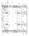
- resin transfer moulding equipment comprises a frame defined by four hollow rolled steel upright pillars la-d of rectangular cross-section secured at their feet to a concrete bed 5 and bolted at their upper ends to an H-frame composed of four hollow rolled steel cross-members 6a-d.
- a first mould half 8 is fixed to the bed 5 by four stands 10a-d.
- Each stand comprises two X-section beams bolted together and upright L-section locating element mounted on the top of each of the upper beams 10.
- the height of the first mould half 8 above the bed 5 can be adjusted by removing one or both the beams in each stand, or by inserting shims (not shown) between the stands and the first mould half 8.
- a second mould half 12 is housed within the frame for vertical movement towards and away from the first mould half, as indicated by solid and broken lines in Figures 1 and 2.
- Each corner of the second mould half 12 carries a mounting bracket 13a-d.
- Carriage pins 14a-d project laterally from each bracket and rest in a respective one of four carriages 15a-d, each of which can travel up and down the pillars 1a-d.
- Each carriage is retained in its raised position by a latch mechanism, one of which is illustrated in detail in Figure 18, comprising a bolt 3 mounted within the upright pillar 1 for movement between an extended position, in which it projects through an aperture in the pillar 1 to engage the lower edge of the carriage 15, and a retracted position.
- the bolt 3 is biased into the extended position by a spring 4, and may be retracted by a pneumatic cylinder 7.
- the lower leading edge of the bolt 3 is chamfered so that upward movement of the carriage 15 past the bolt drives the bolt into the retracted position.
- the two mould halves 8,12 are of similar construction, each comprising a series of vertical metal plates arranged in a rectangular grid which forms a rigid support 9,11 for a shell 17,18, which are illustrated in more detail in Figures 4 to 9.
- the shell 17 of the first mould half is illustrated in Figures 4 to 7.
- the shell is a rectangular plaque mould suitable for producing flat panels of fibre-reinforced plastics material measuring 4mm x 100cm x 150cm.
- Other configurations of shell can of course be used to produce articles of different shapes.
- Non-planar shells would be mounted on a supporting structure preferably in the form of a frame complementary in shape to the reverse face of the shell, and secured to the support 9,11.
- the shell 17 has chromium-plated upper moulding surface 19 and a peripheral rectangular recesses or gallery for receiving a spacer element 20, and a seal 21, as best seen in Figure 5.
- the peripheral recess is provided with apertures 22 (see Figure 6) through the shell at regular intervals, and the spacer and seal 20,21 are configured to expose one or more of the apertures to permit venting of the mould in use.
- Further apertures 23,23 along the centre lines of the shell 17 are provided for the injection of resin into the mould or for measuring instruments, such as thermocouples or transducers.
- the rear surface of the shell 17 is provided with a series of parallel grooves 24 each of which receives a tubular heating element (not shown) through which heated fluid, such as oil, at a predetermined temperature can be passed.
- the heating elements are secured in the recesses by heat-conducting adhesive, such as an aluminium-filled epoxy resin. The flow of heating or cooling fluid through the heating elements can be controlled so that any required temperature gradient can be established across the shell.
- the shell 18 for the second mould half 12 is illustrated in Figures 8 and 9.
- This shell is also a rectangular plaque mould having a plane chromium-plated lower moulding surface 25 and a rear surface having parallel recesses 26 for tubular heating elements.
- a series of apertures 27 arranged on the lateral and longitudinal centre line of the shell are provided for the injection of resin.
- Sensors such as thermocouples and pressure transducers (not shown) may be attached to the shells to enable the progress of the injection process to be monitored.
- Both shells 17,18 are provided with bolt holes to permit the shells to be bolted to the supports.
- the heating system for the shells 17 is illustrated in more detail in Figure 20.
- a similar system is provided for the other shell 18.
- oil is held in a reservoir 150 which contains a heat exchange element 151 through which cooling water can be circulated.
- the flow of water through the heat exchange element is regulated by a thermostatically-controlled valve 153.
- Oil is pumped from the reservoir by a pump 155 along a supply line 156 over an electrically-operated immersion heater 157 and into the array of heating elements 158 in the shell 17. Each element may be opened and closed by a valve 159 so that a desired temperature gradient may be established across the mould surface. Oil emerging from the heating elements is returned to the pump for re-circulation along a return line 160, excess oil being returned via a pump relief line 161. Both the return line 160 and the pump relief line 161 contain check valves 163,164. Hot oil may be returned to the reservoir from the return line through a cooling valve 165.
- the cooling valve is opened and closed by an electronic temperature controller 166, operable in response to a thermostat 169 in the supply line immediately downstream of the heater 157.
- the temperature controller 166 also controls the heater 157 so that the temperature of the oil circulating in the system is either increased, by switching on the heater 157, or decreased by returning hot oil the reservoir through the valve 165.
- the carriages 15a-d are of similar construction, which is illustrated in detail in Figure 12.
- Each carriage comprises two parallel side plates 30,30' disposed on two opposite sides of the upright pillar 1 along which it travels.
- Each plate carries two bearing plates 32,32' each of which overlies one of the other two sides of the pillar 1 so that the side plates and bearing plates embrace opposite sides of the pillar.
- the bearing plates 32,32' each carry an upper roller 34,34' and a lower roller 36,36', which guide the carriage 15 along the pillar. Further guidance for the carriage is provided by two further vertically-spaced rollers mounted in bearing blocks on each of the side plates 30.
- the side plates 30 are bolted to upper and lower spacer bars 42,43 ( Figure 12) on one side of the pillar, and to upper and lower anchor blocks on the other side of the pillar.
- the inwardly-facing edges of the side plates 30,31 are also bolted to a bracket 46 ( Figure 13) which is provided with a semi-circular recess for receiving one of the carriage pins 14 on the second mould half 12.
- Each carriage 15a-d may be moved along the upright pillar 1 by one of four lifting jacks 50a-d of similar construction.
- the lower end of each jack is pivotally connected to the foot of the pillar 1 (as illustrated in detail with respect to one jack 50a in Figure 15), the upper end of each jack is bolted to the bottom of the bracket 46 on the carriage 15.
- All four lifting jacks 50a-d are operable hydraulically from a conventional hydraulic control system (not illustrated).
- the carriages 15a-d are interconnected by a drive mechanism which transfers the movement of one lifting jack to the others.
- the drive mechanism comprises four drive chains 60a-d indicated in broken lines in the drawings. Each drive chain 60a-d is connected at each end to the upper and lower anchor blocks of one of the carriages 15a-d.
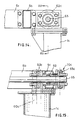
- Each drive chain 60a-d passes upwardly alongside one of the upright pillars 1a-d, over one of four first gear wheels 62a-d mounted in adjustable bearings on top of the pillars 1a-d (illustrated in detail in Figures 14 and 15), down the hollow interior of the pillar, around an idler wheel 64 mounted for rotation in the foot of the pillar 1 (illustrated in detail in Figure 16), through an aperture in the foot of the pillar and upwardly alongside the inner wall of the pillar to the lower anchor block 46 on the carriage 15. Adjustment of the bearings of the gear wheels 62a-d sets the tension in the chains 60a-d to a required level.
- the four first gear wheels 62a-d are coupled together in pairs by two drive shafts 65,66 ( Figures 1 and 2) mounted in self-aligning bearings 69 ( Figure 15) adjacent the cross members 6b and 6d and extending along opposite sides of the frame.
- the ends of the drive shafts 65,66 carry second gear wheels 68a-d.
- Each of the second gear wheels is connected by a drive chains 70a-d to one of four transfer wheels 71a-d (illustrated in detail in Figure 17) which are fixed to shafts 72 a-d mounted for rotation in needle bearings towards the centres of the front and rear crossmembers 6a and 6d.
- the inner ends of the shafts 72a-d carry gear wheels 73a-d which mesh with the gear wheel on the adjacent drive shaft.
- the upper and lower mould halves 12 and 18 may be clamped together in their closed position by six clamps 80, two of which are mounted on each of the longer sides of the mould halves, one further clamp being mounted on each of the shorter sides of the mould halves, as illustrated in Figures 1 and 2.
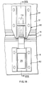
- One clamp 80 is illustrated in more detail in Figures 19 and 21.
- the clamp comprises an upper part 81 and a lower part 82 bolted to the upper and lower mould halves 12,8 respectively.
- the lower part 82 comprises an hydraulic cylinder 85 from which a piston rod 86 projects vertically upwardly through a hollow cylindrical seat 87, which has a conical upper surface 88.
- the upper surface of the seat 87 is received within a collar 90 secured to the upper part 81 of the clamp.
- the lower surface of the collar 90 has a conical surface complementary to the upper surface of the seat 87 so that, as the mould halves close, the two parts of the clamp are guided into alignment.
- the upper end of the piston rod 86 carries a dolly 95 having a spherical head 96 and a cylindrical body 97.
- the head 96 extends into a locking ring 100 which rests on the upper part of the body 97.
- the locking ring can slide partially into the upper end of the collar 90 until a shoulder formed on the external surface of the locking ring engages the upper edge of the collar 90.
- the internal surface of the locking ring is tapered to form a conical seat.
- the upper part 81 of the clamp carries a pneumatic cylinder 110 having a piston rod that carries a collet 112.
- the lower end of the collet 112 is tapered externally to match the seat formed by the internal surface of the locking ring 100, and has a spherical internal recess for receiving the head of the dolly 95.
- Four axial slots in the end of the collet allow the collet to expand whilst the head 96 of the dolly is inserted into the collet 112.
- the shells 17, 18 are bolted to their respective supports and, depending upon the nature of the resin to be used in the moulding process, heated to an operating temperature.
- a preform of fibrous reinforcing material is loaded into the shell 17b of the first mould half.
- the pneumatic cylinders 7 of the latch mechanisms for the carriages 15a-d are then operated to retract the bolts 7, and the lifting jacks are operated to lower the carriages and the second mould half 12 so that the moulding surface 25 of the shell of the second mould half contacts the spacers and seals 20,21 of the shell 17 on the lower mould half.
- the seats 87 of the clamps 80 engage with their respective collars 90 and align the two mould halves accurately.
- the clamps 80 are actuated.
- the hydraulic cylinder 85 is initially actuated to extend the dolly 95.
- the pneumatic piston 110 on the upper part of the clamp is actuated so that the collet 112 engages the head 96 of the dolly and the seat of the locking ring 100.
- the hydraulic cylinder 85 on the lower part of the clamp is then actuated to withdraw the piston 86 so that the locking ring slides into collar 90.
- Liquid resin is then injected into the cavity formed by the two shells 17,18 through one or more of the apertures 23 or 27 of the shells.
- Relatively low pressure is used to inject the resin, for example 2-10 bar, typically 5 bar.
- the rigidity of the supports of the shells is sufficient to prevent distortion of the shells 17,18 during the injection of resin.
- the quality of the moulding is therefore maintained.
- the resin is allowed to cure and the lifting jacks are operated to raise the second mould half 12.
- the upward movement of each carriage 15a-d is transmitted to all the other carriages through the drive chains 60a-d and 70a-d, the drive shafts 65,66 and the gear wheels 62a-d, 68a-d and 73a-d. Consequently, even if the second mould half should stick to the first mould half during separation of the mould halves, the second mould half will be maintained in a horizontal orientation, thereby reducing the risk of damage to the moulding when the two mould halves are separated.
Landscapes
- Engineering & Computer Science (AREA)
- Mechanical Engineering (AREA)
- Chemical & Material Sciences (AREA)
- Composite Materials (AREA)
- Moulds For Moulding Plastics Or The Like (AREA)
- Injection Moulding Of Plastics Or The Like (AREA)
Description
- This invention relates to moulding equipment, particularly resin transfer moulding equipment.
- In many moulding processes, a mould cavity is formed from two separable mould halves. Plastics material is introduced into the mould cavity and allowed to cure. The two mould halves are then separated to allow removal of the cured moulding. In resin transfer moulding, a dry preform of fibrous material, such as glass fibre, is first loaded into the mould cavity and liquid thermosetting resin is used to impregnate the preform and to form the final product.
- Automatic moulding machines are known in which two mould halves are mounted in a frame for movement into and out of a closed position in which they define the mould cavity. For example, US-3380117 and US-3473196 disclose machines of this type in which one of the mould halves may be moved vertically with respect to the other; GB-1541160, GB-2158389 and GB-2064415 disclose moulding equipment in which one of the mould halves is slidable horizontally with respect to the other.
- Problems can arise in maintaining the two mould halves parallel to each other during separation since the two mould halves tend to stick together. Such misalignment can result in damage to the moulding or the equipment. These problems are particularly acute in the production of large generally flat moulding such as vehicle body panels, where more than one actuator is required to separate the mould halves, and the actuators are widely spaced from each other. Japanese patent publications Nos 63-132018, 63-125312 and 63-63-199614 disclose moulding machines in which an equalising mechanism in the form of four inter-connected ball-screws or racks-and-pinions positioned at each corner of the mould half is used to transmit irregularities of movements from any one one corner to the other three. However, all the machines include a single central hydraulic actuator to raise and lower a mould half which is inadequate for large-scale mouldings such as vehicle body panels.
- More particularly, EP-A-285046 (cf. the preamble of claim 1) discloses a device for use in the production of a trough-shaped moulded item, which device comprises a frame in which mould halves are mounted. Means are provided for moving the moulds into and out of a closed position defining a mould cavity into which resin may be introduced. One mould half is movable towards and away from another mould half by means of a carriage at either end and from which centrally positioned support arms for the mould half extend. The carriages are located on guide columns forming part of a frame and are each moved by two screw devices straddling the support arms all of which screw devices are driven by a single motor driven chain.
- According to the present invention there is provided resin transfer moulding equipment comprising a frame having a plurality of pillars (1a-d) on each of which is mounted a carriage (15a-d), first and second mould halves (8,12) mounted in the frame, the second mould half (12) being connected to carriages (15a-d) and moveable into and out of a closed position in which the mould halves (8,12) define a mould cavity into which resin may be introduced, characterised in that each carriage (15a-d) is raised and lowered by a respective one of a plurality of lifting jacks (50a-d), and in that a separate drive mechanism (60a-d) is provided for transferring movement from one lifting jack (50a-d) to the other lifting jack or jacks.
- The lifting jacks facilitate the separation of the mould halves, and the drive mechanism ensures that the separation occurs evenly, which protects the moulding and the equipment from damage during separation and also contributes to a reduction in cycle time for the moulding process.
- The frame preferably comprises a plurality of upright pillars on each of which is mounted a carriage capable of travelling along the pillar, and each carriage is connected to the second mould and to a respective one of the lifting jacks. With such a construction, the drive mechanism preferably comprises chain drives mounted on the frame and interconnecting the carriages.
- Preferably, each mould half comprises a shell defining a mould surface and a support for the shell, the support being sufficiently rigid to prevent deformation of the shell during the moulding process. The shells may be removably mounted on the supports so that the same equipment can be used to produce different mouldings simply by interchanging the shells. In order to accommodate shells of different sizes, the first mould half may be mounted on one or more stands the height of which is adjustable. Alternatively, the first mould half may be mounted for movement out of the frame, for example on rollers, for replacement by another mould half carrying a different shell.
- In the preferred embodiment of the invention, the shells of at least one mould half, and preferably both, comprises means for heating the mould surface, for example in the form of a plurality of heating elements and means for controlling individually the temperatures of the heating elements.
- The mould halves are preferably clamped together in the closed position, the means for moving mould halves being disengagable therefrom when the clamping means is engaged. By separating the operation of the clamping means from the means for moving the mould halves, the means for moving the mould halves offers no resistance to the clamping means, thereby facilitating an accurate alignment of the mould halves in their closed position.
- A preferred embodiment of the invention will now be described, by way of example only, with reference to the accompanying drawings, in which:-
- Figure 1 is a front elevation of resin transfer moulding equipment in accordance with the invention;
- Figure 2 is a side elevation of the equipment of Figure 1 in the direction of the arrow X;
- Figure 3 is a plan of the equipment of Figures 1 and 2;
- Figure 4 is a plan of a mould shell incorporated in the equipment of Figures 1 to 3;
- Figure 5 is a partial cross-section of the mould shell of Figure 4, taken along the line V-V;
- Figure 6 is a plan of the opposite surface of the mould shell of Figure 4;
- Figure 7 is a cross-section through the mould shell taken along line VII-VII of Figure 6;
- Figure 8 is a plan of one side of another mould shell incorporated in the equipment of Figures 1 to 3;
- Figure 9 is a cross-section through the mould shell of Figure 8, taken along line IX-IX of Figure 8;
- Figure 12 is a cross-section of a carriage forming part of the equipment of Figures 1 to 3;
- Figure 13 is a cross-section of the carriage of Figure 4, taken along line XIII-XIII;
- Figure 14 is a cross-section through part of the equipment of Figures 1 to 3, taken along line XIV-XIV in Figure 2;
- Figure 15 is a cross-section taken along line XV-XV of Figure 14;
- Figure 16 is a cross-section through part of the equipment of Figures 1 to 3, taken along line XV-XV in Figure 2;
- Figure 17 is a plan, on an enlarged scale, of the part of the equipment in the circle XVIII in Figure 3;
- Figure 18 is a partial cross-section taken through a carriage latch mechanism employed in the equipment shown in Figure 1;
- Figure 19 is a cross-section along the line XIX of Figure 21;
- Figure 20 is a diagram illustrating a heating system for the mould shells of Figures 4 to 9; and
- Figure 21 is an elevation of clamp used in the equipment of Figure 1;
- Referring to the drawings, resin transfer moulding equipment comprises a frame defined by four hollow rolled steel upright pillars la-d of rectangular cross-section secured at their feet to a
concrete bed 5 and bolted at their upper ends to an H-frame composed of four hollow rolledsteel cross-members 6a-d. - A
first mould half 8 is fixed to thebed 5 by fourstands 10a-d. Each stand comprises two X-section beams bolted together and upright L-section locating element mounted on the top of each of theupper beams 10. The height of thefirst mould half 8 above thebed 5 can be adjusted by removing one or both the beams in each stand, or by inserting shims (not shown) between the stands and thefirst mould half 8. - A
second mould half 12 is housed within the frame for vertical movement towards and away from the first mould half, as indicated by solid and broken lines in Figures 1 and 2. Each corner of thesecond mould half 12 carries a mounting bracket 13a-d.Carriage pins 14a-d project laterally from each bracket and rest in a respective one of fourcarriages 15a-d, each of which can travel up and down thepillars 1a-d. Each carriage is retained in its raised position by a latch mechanism, one of which is illustrated in detail in Figure 18, comprising abolt 3 mounted within theupright pillar 1 for movement between an extended position, in which it projects through an aperture in thepillar 1 to engage the lower edge of thecarriage 15, and a retracted position. Thebolt 3 is biased into the extended position by aspring 4, and may be retracted by apneumatic cylinder 7. The lower leading edge of thebolt 3 is chamfered so that upward movement of thecarriage 15 past the bolt drives the bolt into the retracted position. - The two
mould halves rigid support 9,11 for ashell - The
shell 17 of the first mould half is illustrated in Figures 4 to 7. In the embodiment illustrated, the shell is a rectangular plaque mould suitable for producing flat panels of fibre-reinforced plastics material measuring 4mm x 100cm x 150cm. Other configurations of shell can of course be used to produce articles of different shapes. Non-planar shells would be mounted on a supporting structure preferably in the form of a frame complementary in shape to the reverse face of the shell, and secured to thesupport 9,11. - The
shell 17 has chromium-platedupper moulding surface 19 and a peripheral rectangular recesses or gallery for receiving aspacer element 20, and aseal 21, as best seen in Figure 5. The peripheral recess is provided with apertures 22 (see Figure 6) through the shell at regular intervals, and the spacer andseal Further apertures shell 17 are provided for the injection of resin into the mould or for measuring instruments, such as thermocouples or transducers. The rear surface of theshell 17 is provided with a series ofparallel grooves 24 each of which receives a tubular heating element (not shown) through which heated fluid, such as oil, at a predetermined temperature can be passed. The heating elements are secured in the recesses by heat-conducting adhesive, such as an aluminium-filled epoxy resin. The flow of heating or cooling fluid through the heating elements can be controlled so that any required temperature gradient can be established across the shell. - The
shell 18 for thesecond mould half 12 is illustrated in Figures 8 and 9. This shell is also a rectangular plaque mould having a plane chromium-platedlower moulding surface 25 and a rear surface having parallel recesses 26 for tubular heating elements. A series of apertures 27 arranged on the lateral and longitudinal centre line of the shell are provided for the injection of resin. Sensors such as thermocouples and pressure transducers (not shown) may be attached to the shells to enable the progress of the injection process to be monitored. Bothshells - The heating system for the
shells 17 is illustrated in more detail in Figure 20. A similar system is provided for theother shell 18. As illustrated in Figure 20, oil is held in areservoir 150 which contains a heat exchange element 151 through which cooling water can be circulated. The flow of water through the heat exchange element is regulated by a thermostatically-controlledvalve 153. - Oil is pumped from the reservoir by a
pump 155 along asupply line 156 over an electrically-operatedimmersion heater 157 and into the array ofheating elements 158 in theshell 17. Each element may be opened and closed by avalve 159 so that a desired temperature gradient may be established across the mould surface. Oil emerging from the heating elements is returned to the pump for re-circulation along areturn line 160, excess oil being returned via apump relief line 161. Both thereturn line 160 and thepump relief line 161 contain check valves 163,164. Hot oil may be returned to the reservoir from the return line through a coolingvalve 165. The cooling valve is opened and closed by anelectronic temperature controller 166, operable in response to athermostat 169 in the supply line immediately downstream of theheater 157. Thetemperature controller 166 also controls theheater 157 so that the temperature of the oil circulating in the system is either increased, by switching on theheater 157, or decreased by returning hot oil the reservoir through thevalve 165. Thecarriages 15a-d are of similar construction, which is illustrated in detail in Figure 12. Each carriage comprises twoparallel side plates 30,30' disposed on two opposite sides of theupright pillar 1 along which it travels. Each plate carries two bearingplates 32,32' each of which overlies one of the other two sides of thepillar 1 so that the side plates and bearing plates embrace opposite sides of the pillar. The bearingplates 32,32' each carry anupper roller 34,34' and alower roller 36,36', which guide thecarriage 15 along the pillar. Further guidance for the carriage is provided by two further vertically-spaced rollers mounted in bearing blocks on each of theside plates 30. - The
side plates 30 are bolted to upper and lower spacer bars 42,43 (Figure 12) on one side of the pillar, and to upper and lower anchor blocks on the other side of the pillar. The inwardly-facing edges of theside plates 30,31 are also bolted to a bracket 46 (Figure 13) which is provided with a semi-circular recess for receiving one of the carriage pins 14 on thesecond mould half 12. Eachcarriage 15a-d may be moved along theupright pillar 1 by one of fourlifting jacks 50a-d of similar construction. The lower end of each jack is pivotally connected to the foot of the pillar 1 (as illustrated in detail with respect to onejack 50a in Figure 15), the upper end of each jack is bolted to the bottom of the bracket 46 on thecarriage 15. All four liftingjacks 50a-d are operable hydraulically from a conventional hydraulic control system (not illustrated). - In order to ensure that the four carriages always move in unison, even in the event of failure of one of the jacks, the
carriages 15a-d are interconnected by a drive mechanism which transfers the movement of one lifting jack to the others. The drive mechanism comprises fourdrive chains 60a-d indicated in broken lines in the drawings. Eachdrive chain 60a-d is connected at each end to the upper and lower anchor blocks of one of thecarriages 15a-d. - Each
drive chain 60a-d passes upwardly alongside one of theupright pillars 1a-d, over one of fourfirst gear wheels 62a-d mounted in adjustable bearings on top of thepillars 1a-d (illustrated in detail in Figures 14 and 15), down the hollow interior of the pillar, around anidler wheel 64 mounted for rotation in the foot of the pillar 1 (illustrated in detail in Figure 16), through an aperture in the foot of the pillar and upwardly alongside the inner wall of the pillar to the lower anchor block 46 on thecarriage 15. Adjustment of the bearings of thegear wheels 62a-d sets the tension in thechains 60a-d to a required level. - The four
first gear wheels 62a-d are coupled together in pairs by twodrive shafts 65,66 (Figures 1 and 2) mounted in self-aligning bearings 69 (Figure 15) adjacent thecross members drive shafts second gear wheels 68a-d. Each of the second gear wheels is connected by adrive chains 70a-d to one of fourtransfer wheels 71a-d (illustrated in detail in Figure 17) which are fixed to shafts 72 a-d mounted for rotation in needle bearings towards the centres of the front andrear crossmembers carry gear wheels 73a-d which mesh with the gear wheel on the adjacent drive shaft. As a result, the movement of any onejack 50a-d is transmitted to all four carriages. - The upper and lower mould halves 12 and 18 may be clamped together in their closed position by six
clamps 80, two of which are mounted on each of the longer sides of the mould halves, one further clamp being mounted on each of the shorter sides of the mould halves, as illustrated in Figures 1 and 2. Oneclamp 80 is illustrated in more detail in Figures 19 and 21. - Referring to Figures 19 and 21, the clamp comprises an
upper part 81 and alower part 82 bolted to the upper and lower mould halves 12,8 respectively. Thelower part 82 comprises anhydraulic cylinder 85 from which apiston rod 86 projects vertically upwardly through a hollowcylindrical seat 87, which has a conicalupper surface 88. In the closed position of the mould halves illustrated, the upper surface of theseat 87 is received within acollar 90 secured to theupper part 81 of the clamp. The lower surface of thecollar 90 has a conical surface complementary to the upper surface of theseat 87 so that, as the mould halves close, the two parts of the clamp are guided into alignment. - The upper end of the
piston rod 86 carries adolly 95 having aspherical head 96 and a cylindrical body 97. When thepiston rod 86 is fully extended, as illustrated in Figures 19 and 21, thehead 96 extends into alocking ring 100 which rests on the upper part of the body 97. The locking ring can slide partially into the upper end of thecollar 90 until a shoulder formed on the external surface of the locking ring engages the upper edge of thecollar 90. The internal surface of the locking ring is tapered to form a conical seat. - The
upper part 81 of the clamp carries apneumatic cylinder 110 having a piston rod that carries acollet 112. The lower end of thecollet 112 is tapered externally to match the seat formed by the internal surface of thelocking ring 100, and has a spherical internal recess for receiving the head of thedolly 95. Four axial slots in the end of the collet allow the collet to expand whilst thehead 96 of the dolly is inserted into thecollet 112. - In use, the
shells second mould half 12 in its raised position, a preform of fibrous reinforcing material is loaded into the shell 17b of the first mould half. Thepneumatic cylinders 7 of the latch mechanisms for thecarriages 15a-d are then operated to retract thebolts 7, and the lifting jacks are operated to lower the carriages and thesecond mould half 12 so that themoulding surface 25 of the shell of the second mould half contacts the spacers and seals 20,21 of theshell 17 on the lower mould half. Theseats 87 of theclamps 80 engage with theirrespective collars 90 and align the two mould halves accurately. - Continued downward movement of the carriages causes the brackets 46 to disengage from the carriage pins 14. After the brackets 46 have disengaged from the
pins 14, theclamps 80 are actuated. In each clamp, thehydraulic cylinder 85 is initially actuated to extend thedolly 95. When the mould halves 12, 8 are closed, thepneumatic piston 110 on the upper part of the clamp is actuated so that thecollet 112 engages thehead 96 of the dolly and the seat of thelocking ring 100. Thehydraulic cylinder 85 on the lower part of the clamp is then actuated to withdraw thepiston 86 so that the locking ring slides intocollar 90. In this position, the collet is locked over the head of the dolly, and further actuation of thehydraulic cylinder 85 applies a clamping force to the mould halves 12, 8. In this way the full force of theclamps 80 is applied to the mould halves, and, since the lifting jacks are disengaged from the moulds, none of the clamping force is transmitted to the lifting jacks or the frame. - Liquid resin is then injected into the cavity formed by the two
shells apertures 23 or 27 of the shells. Relatively low pressure is used to inject the resin, for example 2-10 bar, typically 5 bar. The rigidity of the supports of the shells is sufficient to prevent distortion of theshells second mould half 12. The upward movement of eachcarriage 15a-d is transmitted to all the other carriages through thedrive chains 60a-d and 70a-d, thedrive shafts gear wheels 62a-d, 68a-d and 73a-d. Consequently, even if the second mould half should stick to the first mould half during separation of the mould halves, the second mould half will be maintained in a horizontal orientation, thereby reducing the risk of damage to the moulding when the two mould halves are separated.
Claims (5)
- Resin transfer moulding equipment comprising a frame having a plurality of pillars (1a-d) on each of which is movably mounted a carriage (15a-d), first and second mould halves (8,12) mounted in the frame, the second mould half (12) being connected to carriages (15a-d) and moveable into and out of a closed position in which the mould halves (8,12) define a mould cavity into which resin may be introduced, characterised in that each carriage (15a-d) is raised and lowered by a respective one of a plurality of lifting jacks (50a-d), and in that a separate drive mechanism (60a-d) is provided for transferring movement from one lifting jack (50a-d) to the other lifting jack or jacks.
- Equipment according to Claim 1, wherein the drive mechanism comprises chain drives (70a-d) mounted on the frame and interconnecting the carriages (15a-d).
- Equipment according to Claim 1, wherein each mould half (8,12) comprises a shell (17,18) defining the mould surface and a support (9,11) for the shell, the support being sufficiently rigid to prevent deformation of the shell during the moulding process and further comprising means (80) for clamping the mould halves together in the closed position, the means (50a-d) for moving the mould halves (8,12) being disengageable therefrom when the clamping means is engaged.
- Equipment according to Claim 3, wherein at least one shell (17,18) comprises means (24,26,158) for heating the mould surface.
- Equipment according to Claim 5, wherein the means for heating the mould surface comprises a plurality of heating elements (158) and means (157,166) for controlling the temperature of the heating elements.
Applications Claiming Priority (2)
| Application Number | Priority Date | Filing Date | Title |
|---|---|---|---|
| GB8922584 | 1989-10-06 | ||
| GB898922584A GB8922584D0 (en) | 1989-10-06 | 1989-10-06 | Resin transfer moulding equipment |
Publications (3)
| Publication Number | Publication Date |
|---|---|
| EP0421801A2 EP0421801A2 (en) | 1991-04-10 |
| EP0421801A3 EP0421801A3 (en) | 1991-12-11 |
| EP0421801B1 true EP0421801B1 (en) | 1995-09-06 |
Family
ID=10664191
Family Applications (3)
| Application Number | Title | Priority Date | Filing Date |
|---|---|---|---|
| EP19900310906 Expired - Lifetime EP0421800B1 (en) | 1989-10-06 | 1990-10-04 | Resin transfer moulding equipment and method |
| EP90310905A Expired - Lifetime EP0421799B1 (en) | 1989-10-06 | 1990-10-04 | Resin transfer moulding equipment |
| EP19900310907 Expired - Lifetime EP0421801B1 (en) | 1989-10-06 | 1990-10-04 | Resin transfer moulding equipment |
Family Applications Before (2)
| Application Number | Title | Priority Date | Filing Date |
|---|---|---|---|
| EP19900310906 Expired - Lifetime EP0421800B1 (en) | 1989-10-06 | 1990-10-04 | Resin transfer moulding equipment and method |
| EP90310905A Expired - Lifetime EP0421799B1 (en) | 1989-10-06 | 1990-10-04 | Resin transfer moulding equipment |
Country Status (4)
| Country | Link |
|---|---|
| EP (3) | EP0421800B1 (en) |
| DE (3) | DE69022156T2 (en) |
| ES (3) | ES2077651T3 (en) |
| GB (1) | GB8922584D0 (en) |
Families Citing this family (2)
| Publication number | Priority date | Publication date | Assignee | Title |
|---|---|---|---|---|
| US5234332A (en) * | 1991-04-01 | 1993-08-10 | The Dow Chemical Company | Molding process for multiple molds |
| GB9510496D0 (en) * | 1995-05-24 | 1995-07-19 | Ford Motor Co | Resin transfer moulding |
Family Cites Families (4)
| Publication number | Priority date | Publication date | Assignee | Title |
|---|---|---|---|---|
| US3956058A (en) * | 1974-09-13 | 1976-05-11 | Heinrich Wemhoener | Multiple-piston press for synthetic-resin coating of large surface-area workpieces |
| IT1108148B (en) * | 1978-07-11 | 1985-12-02 | Descrovi Mario | STRUCTURE OF MOLDING MACHINE |
| FR2555496A1 (en) * | 1983-11-30 | 1985-05-31 | Gruet Michel | Moulding process using a lost mould |
| DE3712959A1 (en) * | 1987-04-02 | 1988-10-20 | Schock & Co Gmbh | TOWEL-PLASTIC PLASTIC SANITATION OBJECT, IN PARTICULAR BATHTUB |
-
1989
- 1989-10-06 GB GB898922584A patent/GB8922584D0/en active Pending
-
1990
- 1990-10-04 DE DE69022156T patent/DE69022156T2/en not_active Expired - Fee Related
- 1990-10-04 EP EP19900310906 patent/EP0421800B1/en not_active Expired - Lifetime
- 1990-10-04 ES ES90310905T patent/ES2077651T3/en not_active Expired - Lifetime
- 1990-10-04 ES ES90310907T patent/ES2076332T3/en not_active Expired - Lifetime
- 1990-10-04 DE DE69022153T patent/DE69022153T2/en not_active Expired - Fee Related
- 1990-10-04 EP EP90310905A patent/EP0421799B1/en not_active Expired - Lifetime
- 1990-10-04 EP EP19900310907 patent/EP0421801B1/en not_active Expired - Lifetime
- 1990-10-04 DE DE69022154T patent/DE69022154T2/en not_active Expired - Fee Related
- 1990-10-04 ES ES90310906T patent/ES2076331T3/en not_active Expired - Lifetime
Also Published As
| Publication number | Publication date |
|---|---|
| DE69022153T2 (en) | 1996-02-15 |
| ES2076331T3 (en) | 1995-11-01 |
| EP0421800A3 (en) | 1991-12-11 |
| EP0421801A3 (en) | 1991-12-11 |
| DE69022154T2 (en) | 1996-02-15 |
| EP0421800B1 (en) | 1995-09-06 |
| ES2077651T3 (en) | 1995-12-01 |
| EP0421799B1 (en) | 1995-09-06 |
| DE69022154D1 (en) | 1995-10-12 |
| ES2076332T3 (en) | 1995-11-01 |
| EP0421799A3 (en) | 1992-04-15 |
| DE69022156D1 (en) | 1995-10-12 |
| DE69022153D1 (en) | 1995-10-12 |
| GB8922584D0 (en) | 1989-11-22 |
| DE69022156T2 (en) | 1996-02-15 |
| EP0421800A2 (en) | 1991-04-10 |
| EP0421801A2 (en) | 1991-04-10 |
| EP0421799A2 (en) | 1991-04-10 |
Similar Documents
| Publication | Publication Date | Title |
|---|---|---|
| US6613262B1 (en) | Molding system with movable mold modules | |
| KR0155224B1 (en) | Tire vulcanizing system | |
| DE69225351T2 (en) | Mold changing device for tire vulcanizing device | |
| CN1675054B (en) | Apparatus and method for locking a tire curing press | |
| EP1270116B1 (en) | Casting machine and method using horizontally split type metal molds | |
| CN100572021C (en) | A kind of hydraulic tyre vulcanizing machine in column type strap clamp locked mould mode and method for adjusting mould thereof | |
| US9446542B2 (en) | Small footprint apparatus, method, and tooling for molding large thermoplastic parts | |
| EP0421800B1 (en) | Resin transfer moulding equipment and method | |
| EP2590790B1 (en) | Method of loading and unloading a mold on a foam plastics molding machine | |
| CA1096121A (en) | Injection molding divers articles in selectably ordered sequence | |
| CN106427011B (en) | Composite material forming machine | |
| CN110355923B (en) | Compression molding production system of foam composite board | |
| CN113146940A (en) | Quick die change mechanism for injection molding machine | |
| US3936032A (en) | Apparatus with a working platform and adjustable legs therefor | |
| CN211868416U (en) | A round PU air filter production line | |
| CN210758773U (en) | Pressure forming production system of foam composite board | |
| US3266094A (en) | Molding apparatus | |
| EP0311547B1 (en) | Double carriage for automatic tool change in core making machines for casting | |
| JP2000334741A (en) | Apparatus and method for changing mold | |
| CN223960508U (en) | Modularized rapid die change molding machine | |
| CN119635901B (en) | Automatic core stripping device and method | |
| CN213704205U (en) | Frame plate type vulcanizing machine | |
| CN116922670A (en) | Self-consistent opening and closing system of circulation mould | |
| CN224103366U (en) | Full-automatic EVA vertical disc injection molding machine | |
| GB2108895A (en) | Compression moulding reinforced plastics sheet |
Legal Events
| Date | Code | Title | Description |
|---|---|---|---|
| PUAI | Public reference made under article 153(3) epc to a published international application that has entered the european phase |
Free format text: ORIGINAL CODE: 0009012 |
|
| AK | Designated contracting states |
Kind code of ref document: A2 Designated state(s): BE CH DE ES FR GB IT LI NL SE |
|
| PUAL | Search report despatched |
Free format text: ORIGINAL CODE: 0009013 |
|
| AK | Designated contracting states |
Kind code of ref document: A3 Designated state(s): BE CH DE ES FR GB IT LI NL SE |
|
| 17P | Request for examination filed |
Effective date: 19920527 |
|
| 17Q | First examination report despatched |
Effective date: 19930721 |
|
| GRAA | (expected) grant |
Free format text: ORIGINAL CODE: 0009210 |
|
| AK | Designated contracting states |
Kind code of ref document: B1 Designated state(s): BE CH DE ES FR GB IT LI NL SE |
|
| REF | Corresponds to: |
Ref document number: 69022156 Country of ref document: DE Date of ref document: 19951012 |
|
| ITF | It: translation for a ep patent filed | ||
| ET | Fr: translation filed | ||
| REG | Reference to a national code |
Ref country code: ES Ref legal event code: FG2A Ref document number: 2076332 Country of ref document: ES Kind code of ref document: T3 |
|
| PLBE | No opposition filed within time limit |
Free format text: ORIGINAL CODE: 0009261 |
|
| STAA | Information on the status of an ep patent application or granted ep patent |
Free format text: STATUS: NO OPPOSITION FILED WITHIN TIME LIMIT |
|
| 26N | No opposition filed | ||
| REG | Reference to a national code |
Ref country code: GB Ref legal event code: 746 Effective date: 19960907 |
|
| REG | Reference to a national code |
Ref country code: FR Ref legal event code: D6 |
|
| PGFP | Annual fee paid to national office [announced via postgrant information from national office to epo] |
Ref country code: NL Payment date: 19980914 Year of fee payment: 9 |
|
| PGFP | Annual fee paid to national office [announced via postgrant information from national office to epo] |
Ref country code: SE Payment date: 19980918 Year of fee payment: 9 |
|
| PGFP | Annual fee paid to national office [announced via postgrant information from national office to epo] |
Ref country code: BE Payment date: 19980925 Year of fee payment: 9 |
|
| PGFP | Annual fee paid to national office [announced via postgrant information from national office to epo] |
Ref country code: CH Payment date: 19980929 Year of fee payment: 9 |
|
| PGFP | Annual fee paid to national office [announced via postgrant information from national office to epo] |
Ref country code: ES Payment date: 19981020 Year of fee payment: 9 |
|
| PG25 | Lapsed in a contracting state [announced via postgrant information from national office to epo] |
Ref country code: ES Free format text: LAPSE BECAUSE OF NON-PAYMENT OF DUE FEES Effective date: 19991005 |
|
| PG25 | Lapsed in a contracting state [announced via postgrant information from national office to epo] |
Ref country code: SE Free format text: THE PATENT HAS BEEN ANNULLED BY A DECISION OF A NATIONAL AUTHORITY Effective date: 19991030 |
|
| PG25 | Lapsed in a contracting state [announced via postgrant information from national office to epo] |
Ref country code: BE Free format text: LAPSE BECAUSE OF NON-PAYMENT OF DUE FEES Effective date: 19991031 Ref country code: LI Free format text: LAPSE BECAUSE OF NON-PAYMENT OF DUE FEES Effective date: 19991031 Ref country code: CH Free format text: LAPSE BECAUSE OF NON-PAYMENT OF DUE FEES Effective date: 19991031 |
|
| BERE | Be: lapsed |
Owner name: FORD MOTOR CY LTD Effective date: 19991031 |
|
| PG25 | Lapsed in a contracting state [announced via postgrant information from national office to epo] |
Ref country code: NL Free format text: LAPSE BECAUSE OF NON-PAYMENT OF DUE FEES Effective date: 20000501 |
|
| REG | Reference to a national code |
Ref country code: FR Ref legal event code: CD Ref country code: FR Ref legal event code: TP |
|
| REG | Reference to a national code |
Ref country code: CH Ref legal event code: PL |
|
| EUG | Se: european patent has lapsed |
Ref document number: 90310907.2 |
|
| NLV4 | Nl: lapsed or anulled due to non-payment of the annual fee |
Effective date: 20000501 |
|
| REG | Reference to a national code |
Ref country code: GB Ref legal event code: IF02 |
|
| REG | Reference to a national code |
Ref country code: ES Ref legal event code: FD2A Effective date: 20001113 |
|
| PGFP | Annual fee paid to national office [announced via postgrant information from national office to epo] |
Ref country code: GB Payment date: 20050914 Year of fee payment: 16 |
|
| PG25 | Lapsed in a contracting state [announced via postgrant information from national office to epo] |
Ref country code: IT Free format text: LAPSE BECAUSE OF NON-PAYMENT OF DUE FEES;WARNING: LAPSES OF ITALIAN PATENTS WITH EFFECTIVE DATE BEFORE 2007 MAY HAVE OCCURRED AT ANY TIME BEFORE 2007. THE CORRECT EFFECTIVE DATE MAY BE DIFFERENT FROM THE ONE RECORDED. Effective date: 20051004 |
|
| PGFP | Annual fee paid to national office [announced via postgrant information from national office to epo] |
Ref country code: FR Payment date: 20051006 Year of fee payment: 16 |
|
| PGFP | Annual fee paid to national office [announced via postgrant information from national office to epo] |
Ref country code: DE Payment date: 20051031 Year of fee payment: 16 |
|
| REG | Reference to a national code |
Ref country code: FR Ref legal event code: CD Ref country code: FR Ref legal event code: CA |
|
| PG25 | Lapsed in a contracting state [announced via postgrant information from national office to epo] |
Ref country code: DE Free format text: LAPSE BECAUSE OF NON-PAYMENT OF DUE FEES Effective date: 20070501 |
|
| GBPC | Gb: european patent ceased through non-payment of renewal fee |
Effective date: 20061004 |
|
| REG | Reference to a national code |
Ref country code: FR Ref legal event code: ST Effective date: 20070629 |
|
| PG25 | Lapsed in a contracting state [announced via postgrant information from national office to epo] |
Ref country code: GB Free format text: LAPSE BECAUSE OF NON-PAYMENT OF DUE FEES Effective date: 20061004 |
|
| PG25 | Lapsed in a contracting state [announced via postgrant information from national office to epo] |
Ref country code: FR Free format text: LAPSE BECAUSE OF NON-PAYMENT OF DUE FEES Effective date: 20061031 |