EP0421547A1 - Method and device for folding sheets - Google Patents
Method and device for folding sheets Download PDFInfo
- Publication number
- EP0421547A1 EP0421547A1 EP90202639A EP90202639A EP0421547A1 EP 0421547 A1 EP0421547 A1 EP 0421547A1 EP 90202639 A EP90202639 A EP 90202639A EP 90202639 A EP90202639 A EP 90202639A EP 0421547 A1 EP0421547 A1 EP 0421547A1
- Authority
- EP
- European Patent Office
- Prior art keywords
- folding
- pliable material
- roller
- rollers
- feeding plane
- Prior art date
- Legal status (The legal status is an assumption and is not a legal conclusion. Google has not performed a legal analysis and makes no representation as to the accuracy of the status listed.)
- Granted
Links
Images

Classifications
-
- B—PERFORMING OPERATIONS; TRANSPORTING
- B65—CONVEYING; PACKING; STORING; HANDLING THIN OR FILAMENTARY MATERIAL
- B65H—HANDLING THIN OR FILAMENTARY MATERIAL, e.g. SHEETS, WEBS, CABLES
- B65H45/00—Folding thin material
- B65H45/12—Folding articles or webs with application of pressure to define or form crease lines
- B65H45/14—Buckling folders
Definitions
- the invention relates to a method of folding pliable material in the form of assembled or single sheets of paper or similar relatively rigid material which may vary in quality and length, the folding taking place by means of folding rollers arranged approximately diametrically opposite to each other, substantially on either side of a feeding plane, starting from a position of the pliable material in which a part thereof lies in the feeding plane and a part is bent out of said plane and wherein an arcuate part of the portion of the pliable material bent out of the plane is bent further and is conducted to a folding/nipping area between the folding rollers where the folding rollers make the fold and wherein a trailing portion of the pliable material is fed in controlled fashion from the feeding plane.
- the position of the fold can be accurately set relatively to the trailing edge of the pliable material and the position of the folding line can be readily changed by chosing a different length for the portion bent out of the feeding plane in the above mentioned starting position of the pliable material.
- a set of pliable material comprising stacked sheets of different size, can be folded as a whole, and the trailing portion of the pliable material fed from the feeding plane, in which no fold is to be made, may comprise relatively rigid material, such as cardboard or plastic, in virtue of the fact that the trailing portion of the pliable material traverses a substantially straight path during folding.
- a problem involved in such a method is the magnitude of the force required to press the knife against the pliable material for the pliable material to be folded accurately. In particular this is the case when thicker stacks of sheets are being folded, consisting, for example, of eight sheets on top of each other.
- the knife must be controlled with great precision and it forms a long lever whose free end exerts a pressure.
- Such great forces to be exerted by and on the knife and the accurate control of the knife require a robust construction of the knife and its suspension, and, on account of the great mass of the construction, a great power for driving the operations of the knife.
- this method can only be carried out by means of an expensive, powerful and heavily-built machine.
- the invention aims to overcome the above mentioned problems while retaining the advantages of the known method referred to.
- the folding roller By the rotation of the folding roller, against whose outer surface the portion of the pliable material bent out of the supply plane is pressed, the radius of the curve of that bent portion of the pliable material is reduced and that portion of the pliable material is pressed against the folding rollers at the location of the folding nip.
- the curved portion is carried between the folding rollers to a sufficient extent and is pressed against the folding rollers, it is carried along by the folding rollers and conducted through the folding/nipping area, the fold thus being formed.
- Pressing the pliable material against one of the folding rollers can be effected by means of a hold-down roller.
- the hold-down roller can be permanently pressed towards the folding roller, so that no provisions are necessary for lifting the hold-down roller off the outer surface of the folding roller.
- the pliable material Before it is clamped against the folding roller, the pliable material can also be displaced relatively to the outer surface of that folding roller, so that the desired starting position of the pliable material can be achieved independently of the instantaneous direction of rotation of the folding roller.
- the hold-down roller which is pressed towards the folding roller can be driven by means other than the outer surface of the folding roller, at a peripheral velocity which is equal to the peripheral velocity of the folding roller.
- sheets can be prevented from sliding relatively to each other, in particular in the case of pliable material consisting of greater numbers of sheets.
- Such portions of the part of the pliable material that is bent out of the feeding plane as are folded away from the folding roller can be guided to the folding/nipping area by means of guide means which pivot along with the area where the pliable material is clamped against the folding roller.
- guide means which pivot along with the area where the pliable material is clamped against the folding roller.
- the controlled feeding of the trailing portion can be accomplished by pushing against the trailing edge of the pliable material, with the location of said trailing edge being signalled to a control system, which starts the further bending and feeding of the bent portion between the folding rollers depending on the location of said trailing edge and the required distance between said trailing edge and the fold.
- a control system which starts the further bending and feeding of the bent portion between the folding rollers depending on the location of said trailing edge and the required distance between said trailing edge and the fold.
- the location on the pliable material where the fold is made can be set very readily and optionally automatically in virtue of the fact that a portion of the pliable material contiguous to the trailing edge is driven by means of coacting rollers on opposite sides of the pliable material, while the angular displacement of the rollers is signalled to a control system which starts the further folding over and conducting of the bent portion between the folding rollers, depending on the location of the said trailing edge and the required distance between the said trailing edge and the fold.
- the invention also relates to a folding device for folding pliable material in the form of assembled or single sheets of paper or similar relatively rigid material, which may vary in quality and length, comprising a feeding plane for the pliable material, at least one pair of folding rollers arranged approximately diametrically opposite each other, substantially on either side of the feeding plane, said folding rollers having opposite outer surface portions forming a folding/nipping area in a position substantially in the feeding plane, a movable feeding guide adapted to intersect the feeding plane, and means for bending and conducting a bent portion of the pliable material towards the folding/nipping area.
- the means for conducting the bent portion of the pliable material towards the folding/nipping area are formed as at least one hold-down element adapted to exert a pressure force on one of said folding rollers.
- the invention provides a device which can be used for carrying out the method according to the invention and which may be of relatively light construction.
- the embodiment of the invention shown in Fig. 1 comprises a pliable material table 1 for supporting a portion 3 of the pliable material 2 in a position at least approximately in the feeding plane 17.
- a portion 4 of the pliable material 2 is bent out of the feeding plane 17.
- the portion 4 of the pliable material 2 rests against an upper folding roller 5.
- a lower folding roller 6 Arranged opposite the upper folding roller 5 is a lower folding roller 6. Rollers 5 and 6 are arranged on opposite sides of the feeding plane 17 and opposite outer surface portions of the folding rollers 5 and 6 form a folding nip 7 disposed in the feeding plane 17.
- a hold-down element Arranged on the supply side opposite a segment of the upper folding roller 5, remote from the feeding plane 17, is a hold-down element which is formed as a hold-down roller 8.
- the hold-down roller 8 is suspended by means of a rocker 9, a control rod 10 engaging the rocker 9, which rod in turn is connected to an electromagnet 11.
- the hold-down roller 8 is in a position where it is lifted off the upper folding roller 5.
- a feeding guide 12 is arranged between the pliable material table 1 and the folding nip 7 in a position where it intersects the feeding plane 17, in which position the feeding guide 12 can be used for guiding the pliable material 2 to a starting position as shown in Fig. 1.
- the folding rollers 5 and 6 rotate in the direction as shown by the arrows 13 and 14.
- the edge of the pliable material 2 which is remote from the folding nip 7 abuts against a slide 15.
- the hold-down roller 8 is lifted off the folding roller 5, optionally further pliable material can be added to the pliable material 2, without the folding roller 5 engaging the pliable material resting against it. Because the hold-down roller 8 is lifted off the folding roller 5, no provisions are required for interrupting the drive of the folding roller 5, for example by means of a clutch.
- the position of the slide 15 in the starting position determines the distance between the fold to be made and the trailing edge of the pliable material 2 which rests against the slide 15.
- the folding rollers 5 and 6 can each form a roller of a conveyor belt, in which case the folding/nipping area 7 is formed by the outer surface portions oppositely arranged between the two conveyor belts.
- Fig. 2 shows the hold-down roller 8 in a position where it is pressed against the folding roller 5 by means of the electromagnet 11.
- the folding roller 5 engages the pliable material 2 so that the pliable material 2 is carried along by the rotation of the folding roller 5 and the portion 4 of the pliable material 2 which is bent out of the feeding plane 17 is further folded over.
- the feeding guide 12 is in a position where it is swung down so that it does not prevent the portion 4 of the pliable material 2 which is bent out of the feeding plane 17 from being folded over further.
- the curve of the pliable material 2 is flattened so that a fold 16 is made therein. Then the pliable material 2 is conveyed further, as shown in Fig. 4. It is observed that the portion 3 of the pliable material 2, which is disposed in the feeding plane 17 at the stage shown in Fig. 2 is hardly bent, if at all, during the folding, so that relatively rigid elements, such as plastic identification cards and flat cardboard objects may be incorporated therein.
- the hold-down element is formed as a hold-down roller 8
- the pliable material 2 can be kept fixated against that folding roller 5 upon displacement of the folding roller 5 without the hold-down element rotating along with the folding roller 5.
- the slide 15 may be coupled to a control system which is adapted to operate the electromagnet 11 and the feeding guide 12 depending on the location of the slide 15 relative to the folding rollers 5 and 6 and on the required distance between the fold and the edge of the pliable material 2 remote from the folding rollers 5 and 6.
- a further improved control of the location where the fold is made can be achieved by mounting the hold-down element for rotation about the centerline of the folding roller 5 along a path on the supply side of the folding roller 5 between a position where the hold-down element is opposite a segment of the folding roller 5 that is turned away from the feeding plane 17 and a position where the hold-down element is opposite a segment of that folding roller 5 that is turned towards that feeding plane 17, as shown in Fig. 5.
- Fig. 7 shows the embodiment according to Fig. 5 in which the folding roller 5 comprises a shaft 35 and the clutch between the rocker 21 and the shaft 35 of the folding roller 5 is formed as a helical spring 33 clamped about said shaft.
- the hold-down roller 8 is pressed against the folding roller 5 by means of springs 36 and 36′ and the direction of rotation of at least the folding roller 5 corresponding with that hold-down roller 8 is reversible.
- the hold-down roller 8 is pressed against the folding roller 5, with the folding roller 5 rotating in such a direction that the outer surface in the folding nip 7 moves in a direction opposite to the direction of supply.
- the pliable material can be carried along between and by the rotating folding roller 5 and the hold-down roller 8 rotating along with it. Accordingly, it is not necessary to provide means for lifting the folding roller 5 off the hold-down roller 8, while at the same time the simultaneous rotation of the two oppositely arranged rollers facilitates the introduction of the pliable material between them.
- the hold-down roller 8 By adapting the hold-down roller 8 to be driven by means other than its outer surface, sheets can be prevented from sliding relatively to each other, particularly when the pliable material is composed of greater numbers of sheets.
- the hold-down roller 8 is connected, under restraint from rotation, with a toothed driving wheel 25 which is driven in a fixed ratio corresponding with the effective circumference of the respective rollers 5 and 8.
- the toothed driving wheel 25 meshes with a correspondingly toothed driving wheel 26 which is connected, under restraint from rotation, with the folding roller 5, driving wheel 26 in turn meshing with a toothed driving wheel 27 which is connected, under restraint from rotation, with the folding roller 6.
- the folding rollers 5 and 6 are connected with toothed driving wheels 30 and 31, respectively, via couplings 28 and 29, respectively, said driving wheels being driven in one and the same direction.
- the direction of rotation of the folding rollers 5 and 6 can be set for the introduction or the folding of the pliable material.
- One embodiment particularly advantageous for reversing sheets, comprises a feed-through guide 23 mounted on the rocker 21, which guide 23 extends on the side of the hold-down element that is proximal to the feeding plane 17 (Fig. 5). It is adapted to conduct the initially trailing edge of the pliable material as a new leading edge to the folding/nipping area, there to be caught by the folding rollers. Further, when a fold is to be made in pliable material of which a portion is already folded, the feed-through guide 23 can prevent the portion already folded over from being bent back along the portion of the pliable material that is bent out of the feeding plane 17 when the latter portion is being folded over.
- This flap guide 24 can prevent an already folded-over portion of pliable material to be further folded from being folded back when a free end thereof passes the hold-down element in the direction of the feeding plane 17.
- the embodiment shown in Fig. 5 further comprises feeding rollers 18 and 19 on opposite sides of the feeding plane 17 for supplying the pliable material 2 to the folding nip 7.
- an eye 20 arranged above the feeding plane 17 is an eye 20 adapted to detect the passage of the edge of the pliable material remote from the folding rollers 5 and 6 for operating the drive of the folding rollers which carry along the pliable material.
- the location of the eye 20 can be adjustable.
- the eye 20 as well as the drive of the feeding rollers 18 and 19 is coupled to a control means which operates the drive of the folding rollers 5 and 6 after the feeding rollers 18 and 19 have gone through an angular displacement which is dependent upon the required distance between the fold to be made and the edge of the pliable material remote from the folding rollers 5 and 6.
- the embodiment shown in Fig. 6 comprises two sets of folding rollers 5 and 6 as well as 5′ and 6′.
- the folding rollers 5 and 6 arranged on opposite sides of the feeding plane upstream of the folding rollers 5′ and 6′ are at the same time feeding rollers for feeding pliable material into a subsequent starting position for a next fold to be made or for the pliable material to be reversed by means of the folding rollers 5′ and 6′.
- the feeding guide 32 is so constructed that it can be brought into two positions intersecting the extension of the feeding plane 17 and being substantially mirror-symmetrical relatively to that plane, there being provide at least one hold-down element on both one side of the feeding plane 17 and on the other side thereof.
- a portion of the pliable material is bent out of the feeding plane 17 in the direction of that folding roller 5′ or 6′ which the feeding guide 32 is directed at.
Landscapes
- Folding Of Thin Sheet-Like Materials, Special Discharging Devices, And Others (AREA)
Abstract
Description
- The invention relates to a method of folding pliable material in the form of assembled or single sheets of paper or similar relatively rigid material which may vary in quality and length, the folding taking place by means of folding rollers arranged approximately diametrically opposite to each other, substantially on either side of a feeding plane, starting from a position of the pliable material in which a part thereof lies in the feeding plane and a part is bent out of said plane and wherein an arcuate part of the portion of the pliable material bent out of the plane is bent further and is conducted to a folding/nipping area between the folding rollers where the folding rollers make the fold and wherein a trailing portion of the pliable material is fed in controlled fashion from the feeding plane.
- Such a method is known from Dutch laid-open patent application 8702456. In this method the curve of the portion of the pliable material that is bent out of the feeding plane is rendered more acute by pressing a so-called folding knife against it until the bent portion has a small radius and is pressed between the folding rollers. The portion pressed between the folding rollers and, subsequently, the remaining portions of the pliable material are conducted through the folding nip by the folding rollers, so that the fold is made. This folding method can be used very universally. The position of the fold can be accurately set relatively to the trailing edge of the pliable material and the position of the folding line can be readily changed by chosing a different length for the portion bent out of the feeding plane in the above mentioned starting position of the pliable material. A set of pliable material, comprising stacked sheets of different size, can be folded as a whole, and the trailing portion of the pliable material fed from the feeding plane, in which no fold is to be made, may comprise relatively rigid material, such as cardboard or plastic, in virtue of the fact that the trailing portion of the pliable material traverses a substantially straight path during folding.
- A problem involved in such a method, however, is the magnitude of the force required to press the knife against the pliable material for the pliable material to be folded accurately. In particular this is the case when thicker stacks of sheets are being folded, consisting, for example, of eight sheets on top of each other. Further, the knife must be controlled with great precision and it forms a long lever whose free end exerts a pressure. Such great forces to be exerted by and on the knife and the accurate control of the knife require a robust construction of the knife and its suspension, and, on account of the great mass of the construction, a great power for driving the operations of the knife. As a result, this method can only be carried out by means of an expensive, powerful and heavily-built machine.
- The invention aims to overcome the above mentioned problems while retaining the advantages of the known method referred to.
- This object is accomplished in accordance with the invention in virtue of the fact that the arcuate part of the pliable material is bent further and conducted to the folding/nipping area between the folding rollers by pressing the portion of the pliable material bent out of the feeding plane in at least one place against the closest folding roller and rotating said folding roller.
- By the rotation of the folding roller, against whose outer surface the portion of the pliable material bent out of the supply plane is pressed, the radius of the curve of that bent portion of the pliable material is reduced and that portion of the pliable material is pressed against the folding rollers at the location of the folding nip. When the curved portion is carried between the folding rollers to a sufficient extent and is pressed against the folding rollers, it is carried along by the folding rollers and conducted through the folding/nipping area, the fold thus being formed.
- Owing to the fact that the pliable material, to prevent it from sliding along the folding roller, is kept fixated in the vicinity of the folding/nipping area, an accurate control of the formation of the curve with the reduced radius is achieved and, accordingly, an accurate control of the position of the fold. The forces required to further bend the portion of the pliable material that is bent out of the feeding plane are relatively small in virtue of the fact that when the portion bent out of the feeding plane is further bent, portions thereof are pressed towards each other.
- Pressing the pliable material against one of the folding rollers can be effected by means of a hold-down roller. This offers the advantage that the position of the hold-down element may, in circumferential direction relative to the folding roller, by independent of the rotation of that folding roller.
- The hold-down roller can be permanently pressed towards the folding roller, so that no provisions are necessary for lifting the hold-down roller off the outer surface of the folding roller.
- Before it is clamped against the folding roller, the pliable material can also be displaced relatively to the outer surface of that folding roller, so that the desired starting position of the pliable material can be achieved independently of the instantaneous direction of rotation of the folding roller.
- The hold-down roller which is pressed towards the folding roller can be driven by means other than the outer surface of the folding roller, at a peripheral velocity which is equal to the peripheral velocity of the folding roller. Thus, sheets can be prevented from sliding relatively to each other, in particular in the case of pliable material consisting of greater numbers of sheets.
- Accurate control of the position where the fold is made is accomplished in virtue of the fact that the area where the pliable material is clamped against the folding roller when the arcuate portion of the pliable material is further bent and fed between the folding rollers is pivoted about the axis of rotation and in the direction of rotation of the folding roller. The pliable material is retained between the folding roller and the hold-down element close to that location.
- Such portions of the part of the pliable material that is bent out of the feeding plane as are folded away from the folding roller can be guided to the folding/nipping area by means of guide means which pivot along with the area where the pliable material is clamped against the folding roller. Thus, those parts of the pliable material that are already folded over can be prevented from being pressed towards the pliable material so that upon their passage between the folding rollers they do not unfold or are double-folded in undesirable locations.
- The controlled feeding of the trailing portion can be accomplished by pushing against the trailing edge of the pliable material, with the location of said trailing edge being signalled to a control system, which starts the further bending and feeding of the bent portion between the folding rollers depending on the location of said trailing edge and the required distance between said trailing edge and the fold. By the operation of this control system the location on the pliable material where the fold is made can then be set very readily and optionally automatically.
- According to an alternative embodiment of the invention, the location on the pliable material where the fold is made can be set very readily and optionally automatically in virtue of the fact that a portion of the pliable material contiguous to the trailing edge is driven by means of coacting rollers on opposite sides of the pliable material, while the angular displacement of the rollers is signalled to a control system which starts the further folding over and conducting of the bent portion between the folding rollers, depending on the location of the said trailing edge and the required distance between the said trailing edge and the fold.
- For several mutually parallel folds to be made in the pliable material, with portions of the material to be folded being folded over in successive directions to be randomly determined, after the first fold at least one subsequent fold can be made, with the direction in which the leading portion of the pliable material is folded over relatively to the trailing portion of the pliable material being determined by the bending of said leading edge and a contiguous portion of the pliable material out of the feeding plane in a direction corresponding with the folding over direction, while the direction in which the leading edge and the contiguous portion of the pliable material are bent out of the feeding plane is determined by bringing a guide member in a position in which it intersects the feeding plane obliquely in the folding over direction, as viewed in the direction of transport.
- The invention also relates to a folding device for folding pliable material in the form of assembled or single sheets of paper or similar relatively rigid material, which may vary in quality and length, comprising a feeding plane for the pliable material, at least one pair of folding rollers arranged approximately diametrically opposite each other, substantially on either side of the feeding plane, said folding rollers having opposite outer surface portions forming a folding/nipping area in a position substantially in the feeding plane, a movable feeding guide adapted to intersect the feeding plane, and means for bending and conducting a bent portion of the pliable material towards the folding/nipping area.
- According to the invention, the means for conducting the bent portion of the pliable material towards the folding/nipping area are formed as at least one hold-down element adapted to exert a pressure force on one of said folding rollers.
- Thus the invention provides a device which can be used for carrying out the method according to the invention and which may be of relatively light construction.
- The invention will now be further explained and illustrated with reference to a number of embodiments as shown in the accompanying drawings, in which
- Figs. 1-4 are schematic representations of side-elevational views of a device according to the invention in successive stages of the processing of a sheet.
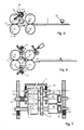
- Figs. 5 and 6 are schematic side-elevational views of further embodiments of the invention; and
- Fig. 7 is a schematic sectional view taken on the line VII-VII of Fig. 5.
- Like parts in the various Figures are designated by like reference numerals.
- The embodiment of the invention shown in Fig. 1 comprises a pliable material table 1 for supporting a
portion 3 of thepliable material 2 in a position at least approximately in thefeeding plane 17. Aportion 4 of thepliable material 2 is bent out of thefeeding plane 17. Theportion 4 of thepliable material 2 rests against anupper folding roller 5. Arranged opposite theupper folding roller 5 is alower folding roller 6.Rollers feeding plane 17 and opposite outer surface portions of thefolding rollers nip 7 disposed in thefeeding plane 17. Arranged on the supply side opposite a segment of theupper folding roller 5, remote from thefeeding plane 17, is a hold-down element which is formed as a hold-down roller 8. The hold-down roller 8 is suspended by means of arocker 9, acontrol rod 10 engaging therocker 9, which rod in turn is connected to anelectromagnet 11. The hold-down roller 8 is in a position where it is lifted off theupper folding roller 5. Arranged between the pliable material table 1 and thefolding nip 7 is afeeding guide 12 in a position where it intersects thefeeding plane 17, in which position thefeeding guide 12 can be used for guiding thepliable material 2 to a starting position as shown in Fig. 1. Thefolding rollers arrows pliable material 2 which is remote from the foldingnip 7 abuts against aslide 15. - Because the hold-
down roller 8 is lifted off the foldingroller 5, optionally further pliable material can be added to thepliable material 2, without the foldingroller 5 engaging the pliable material resting against it. Because the hold-down roller 8 is lifted off the foldingroller 5, no provisions are required for interrupting the drive of thefolding roller 5, for example by means of a clutch. - The position of the
slide 15 in the starting position determines the distance between the fold to be made and the trailing edge of thepliable material 2 which rests against theslide 15. - Optionally, the
folding rollers nipping area 7 is formed by the outer surface portions oppositely arranged between the two conveyor belts. - Fig. 2 shows the hold-
down roller 8 in a position where it is pressed against thefolding roller 5 by means of theelectromagnet 11. Thefolding roller 5 engages thepliable material 2 so that thepliable material 2 is carried along by the rotation of thefolding roller 5 and theportion 4 of thepliable material 2 which is bent out of thefeeding plane 17 is further folded over. Thefeeding guide 12 is in a position where it is swung down so that it does not prevent theportion 4 of thepliable material 2 which is bent out of thefeeding plane 17 from being folded over further. - When said
portion 4 of thepliable material 2 is folding over, theslide 15 is displaced towards the foldingnip 7 so that the curve of thepliable material 2, whose radius is gradually reduced, is pressed against thefolding rollers nip 7 between thefolding rollers - Upon passing the folding
nip 7, the curve of thepliable material 2 is flattened so that afold 16 is made therein. Then thepliable material 2 is conveyed further, as shown in Fig. 4. It is observed that theportion 3 of thepliable material 2, which is disposed in thefeeding plane 17 at the stage shown in Fig. 2 is hardly bent, if at all, during the folding, so that relatively rigid elements, such as plastic identification cards and flat cardboard objects may be incorporated therein. - In virtue of the fact that the hold-down element is formed as a hold-
down roller 8, thepliable material 2 can be kept fixated against that foldingroller 5 upon displacement of thefolding roller 5 without the hold-down element rotating along with thefolding roller 5. - The
slide 15 may be coupled to a control system which is adapted to operate theelectromagnet 11 and thefeeding guide 12 depending on the location of theslide 15 relative to thefolding rollers pliable material 2 remote from thefolding rollers - A further improved control of the location where the fold is made can be achieved by mounting the hold-down element for rotation about the centerline of the
folding roller 5 along a path on the supply side of thefolding roller 5 between a position where the hold-down element is opposite a segment of thefolding roller 5 that is turned away from thefeeding plane 17 and a position where the hold-down element is opposite a segment of thatfolding roller 5 that is turned towards thatfeeding plane 17, as shown in Fig. 5. - Preferably the
rocker 21 is coupled to a shaft of thecorresponding folding roller 5. Thus, the pivoting movement of therocker 21, which is to take place each time the direction of rotation of the folding roller is reversed, can be driven in an easy manner. Fig. 7 shows the embodiment according to Fig. 5 in which thefolding roller 5 comprises ashaft 35 and the clutch between therocker 21 and theshaft 35 of thefolding roller 5 is formed as ahelical spring 33 clamped about said shaft. - According to the embodiments of the invention shown in Figs. 5 and 7 the hold-down
roller 8 is pressed against thefolding roller 5 by means ofsprings folding roller 5 corresponding with that hold-downroller 8 is reversible. When the pliable material is introduced, the hold-downroller 8 is pressed against thefolding roller 5, with thefolding roller 5 rotating in such a direction that the outer surface in the folding nip 7 moves in a direction opposite to the direction of supply. The pliable material can be carried along between and by therotating folding roller 5 and the hold-downroller 8 rotating along with it. Accordingly, it is not necessary to provide means for lifting thefolding roller 5 off the hold-downroller 8, while at the same time the simultaneous rotation of the two oppositely arranged rollers facilitates the introduction of the pliable material between them. - By adapting the hold-down
roller 8 to be driven by means other than its outer surface, sheets can be prevented from sliding relatively to each other, particularly when the pliable material is composed of greater numbers of sheets. According to the embodiment of the invention shown in Fig. 7, the hold-downroller 8 is connected, under restraint from rotation, with atoothed driving wheel 25 which is driven in a fixed ratio corresponding with the effective circumference of therespective rollers toothed driving wheel 25 meshes with a correspondinglytoothed driving wheel 26 which is connected, under restraint from rotation, with thefolding roller 5, drivingwheel 26 in turn meshing with atoothed driving wheel 27 which is connected, under restraint from rotation, with thefolding roller 6. Thefolding rollers toothed driving wheels couplings coupling 30 or theother coupling 31, the direction of rotation of thefolding rollers - One embodiment, particularly advantageous for reversing sheets, comprises a feed-through
guide 23 mounted on therocker 21, which guide 23 extends on the side of the hold-down element that is proximal to the feeding plane 17 (Fig. 5). It is adapted to conduct the initially trailing edge of the pliable material as a new leading edge to the folding/nipping area, there to be caught by the folding rollers. Further, when a fold is to be made in pliable material of which a portion is already folded, the feed-throughguide 23 can prevent the portion already folded over from being bent back along the portion of the pliable material that is bent out of the feedingplane 17 when the latter portion is being folded over. - Provided at the side of the
rocker 21 remote from the feedingplane 17 is aflap guide 24. This flap guide 24 can prevent an already folded-over portion of pliable material to be further folded from being folded back when a free end thereof passes the hold-down element in the direction of the feedingplane 17. - The embodiment shown in Fig. 5 further comprises feeding
rollers plane 17 for supplying thepliable material 2 to the folding nip 7. Arranged above the feedingplane 17 is aneye 20 adapted to detect the passage of the edge of the pliable material remote from thefolding rollers folding rollers eye 20 can be adjustable. Preferably, however, theeye 20 as well as the drive of the feedingrollers folding rollers feeding rollers folding rollers - The embodiment shown in Fig. 6 comprises two sets of
folding rollers folding rollers folding rollers 5′ and 6′ are at the same time feeding rollers for feeding pliable material into a subsequent starting position for a next fold to be made or for the pliable material to be reversed by means of thefolding rollers 5′ and 6′. - To provide the possibility of making folds in different directions, the feeding
guide 32 is so constructed that it can be brought into two positions intersecting the extension of the feedingplane 17 and being substantially mirror-symmetrical relatively to that plane, there being provide at least one hold-down element on both one side of the feedingplane 17 and on the other side thereof. In accordance with the position of the feedingguide 32, a portion of the pliable material is bent out of the feedingplane 17 in the direction of thatfolding roller 5′ or 6′ which the feedingguide 32 is directed at.
Claims (23)
Applications Claiming Priority (2)
| Application Number | Priority Date | Filing Date | Title |
|---|---|---|---|
| NL8902476A NL8902476A (en) | 1989-10-05 | 1989-10-05 | METHOD AND DEVICE FOR FOLDING SHEETS. |
| NL8902476 | 1989-10-05 |
Publications (2)
| Publication Number | Publication Date |
|---|---|
| EP0421547A1 true EP0421547A1 (en) | 1991-04-10 |
| EP0421547B1 EP0421547B1 (en) | 1995-06-21 |
Family
ID=19855403
Family Applications (1)
| Application Number | Title | Priority Date | Filing Date |
|---|---|---|---|
| EP90202639A Expired - Lifetime EP0421547B1 (en) | 1989-10-05 | 1990-10-04 | Method and device for folding sheets |
Country Status (4)
| Country | Link |
|---|---|
| US (1) | US5090671A (en) |
| EP (1) | EP0421547B1 (en) |
| DE (1) | DE69020291T2 (en) |
| NL (1) | NL8902476A (en) |
Cited By (5)
| Publication number | Priority date | Publication date | Assignee | Title |
|---|---|---|---|---|
| EP0556922A1 (en) * | 1992-02-18 | 1993-08-25 | Hadewe B.V. | A method for assembling a postal item as well as a system and an aligning station for carrying out this method |
| EP0623543A1 (en) * | 1993-05-03 | 1994-11-09 | Secap | Folding device for documents with a pivotable guide |
| EP2210844A1 (en) | 2009-01-26 | 2010-07-28 | Neopost Technologies | Method and apparatus for feeding and folding sheets |
| CN111703236A (en) * | 2020-06-23 | 2020-09-25 | 范德霞 | Simple brochure binding machine |
| US11225391B2 (en) | 2018-09-11 | 2022-01-18 | Hewlett-Packard Development Company, L.P. | Sheet folding device with conveying roller capable of partially rotating around folding roller |
Families Citing this family (19)
| Publication number | Priority date | Publication date | Assignee | Title |
|---|---|---|---|---|
| US5183246A (en) * | 1991-10-21 | 1993-02-02 | Pitney Bowes Inc. | Diverting apparatus and method for in-line inserting equipment |
| US5425696A (en) * | 1992-02-19 | 1995-06-20 | Fuji Xerox Co., Ltd. | Swing chute paper folding apparatus with active guide |
| US5876027A (en) * | 1995-06-15 | 1999-03-02 | Canon Aptex Inc. | Sheet bundle folding apparatus |
| US5743517A (en) * | 1996-05-14 | 1998-04-28 | Bergeron; Eugene John | Loose signature ejector assembly in a folding apparatus |
| US6746389B2 (en) * | 1997-10-31 | 2004-06-08 | Cmd Corporation | Method and apparatus for folding or separating bags |
| JP3744234B2 (en) * | 1998-11-10 | 2006-02-08 | コニカミノルタホールディングス株式会社 | Sheet post-processing apparatus and image forming apparatus |
| NL1014000C2 (en) | 1999-12-31 | 2001-07-09 | Neopost Bv | Method and device for assembling mail items with selective envelope selection. |
| GB0107883D0 (en) * | 2001-03-29 | 2001-05-23 | Morgana Systems Ltd | Folding machine |
| US6663551B2 (en) * | 2001-10-26 | 2003-12-16 | Pitney Bowes Inc. | Buckle chute folding machine with a deflector control mechanism |
| GB2397816B (en) * | 2002-12-20 | 2005-03-16 | Pfe Internat Ltd | Document folding apparatus |
| US6981938B2 (en) * | 2003-08-15 | 2006-01-03 | Xerox Corporation | Booklet maker with crease rolls having a slip clutch |
| US7407161B2 (en) * | 2003-10-01 | 2008-08-05 | Fpna Acquisition Corporation | Method of and assembly for lapping consecutive sheets of web material |
| US20060180970A1 (en) * | 2004-09-13 | 2006-08-17 | Nisca Corporation | Sheet finishing apparatus and image forming apparatus equipped with the same |
| NL1027939C2 (en) * | 2004-12-31 | 2006-07-03 | Neopost Sa | Method and device for folding sheets of paper. |
| EP2202190B1 (en) | 2008-12-24 | 2012-02-01 | Neopost Technologies | Apparatus and method for gathering documents |
| EP2216282B1 (en) | 2009-02-09 | 2012-07-04 | Neopost Technologies | Method and apparatus for preparing mail pieces |
| US8617040B2 (en) * | 2010-12-17 | 2013-12-31 | Kimberly-Clark Worldwide, Inc. | Folding apparatus and method of folding a product |
| JP7312987B2 (en) * | 2019-11-26 | 2023-07-24 | デュプロ精工株式会社 | paper folding device |
| JP7762893B2 (en) * | 2022-04-27 | 2025-10-31 | デュプロ精工株式会社 | Paper folding device |
Citations (3)
| Publication number | Priority date | Publication date | Assignee | Title |
|---|---|---|---|---|
| DE2757182A1 (en) * | 1977-12-22 | 1979-06-28 | Baeuerle Gmbh Mathias | Sheet folding machine - has friction restrictors halting and deflecting sheet for folding, controlled by programmable regulator |
| EP0312178A1 (en) * | 1987-10-14 | 1989-04-19 | Hadewe B.V. | A method and an apparatus for folding pliable material, such as documents, which may differ in quality and length and which are conveyed in assembled form or successively |
| EP0312177A1 (en) * | 1987-10-14 | 1989-04-19 | Hadewe B.V. | A method and an apparatus for folding paperlike material, such as documents, which may differ in quality and length and which are conveyed in assembled form or successively |
Family Cites Families (5)
| Publication number | Priority date | Publication date | Assignee | Title |
|---|---|---|---|---|
| US3572688A (en) * | 1968-11-06 | 1971-03-30 | Dan D Mazzolla | Final folder for flatwork |
| US4279611A (en) * | 1980-01-07 | 1981-07-21 | Labombarde Raymond A | Apparatus and method for folding blanks with an unusually elongated wall |
| DE3618921A1 (en) * | 1986-06-05 | 1987-12-10 | Frankenthal Ag Albert | FOLDING APPARATUS |
| JPH0641345B2 (en) * | 1986-11-26 | 1994-06-01 | 株式会社サン精機製作所 | Sheet folding device |
| FR2626564A1 (en) * | 1988-01-29 | 1989-08-04 | Alcatel Satmam | UNIVERSAL FOLDER |
-
1989
- 1989-10-05 NL NL8902476A patent/NL8902476A/en not_active Application Discontinuation
-
1990
- 1990-10-04 DE DE69020291T patent/DE69020291T2/en not_active Expired - Fee Related
- 1990-10-04 EP EP90202639A patent/EP0421547B1/en not_active Expired - Lifetime
- 1990-10-05 US US07/593,876 patent/US5090671A/en not_active Expired - Lifetime
Patent Citations (3)
| Publication number | Priority date | Publication date | Assignee | Title |
|---|---|---|---|---|
| DE2757182A1 (en) * | 1977-12-22 | 1979-06-28 | Baeuerle Gmbh Mathias | Sheet folding machine - has friction restrictors halting and deflecting sheet for folding, controlled by programmable regulator |
| EP0312178A1 (en) * | 1987-10-14 | 1989-04-19 | Hadewe B.V. | A method and an apparatus for folding pliable material, such as documents, which may differ in quality and length and which are conveyed in assembled form or successively |
| EP0312177A1 (en) * | 1987-10-14 | 1989-04-19 | Hadewe B.V. | A method and an apparatus for folding paperlike material, such as documents, which may differ in quality and length and which are conveyed in assembled form or successively |
Non-Patent Citations (1)
| Title |
|---|
| IBM TECHNICAL DISCLOSURE BULLETIN. vol. 30, no. 4, 4 September 1987, NEW YORK US pages 1637 - 1638; "Prefold Mechanism" * |
Cited By (9)
| Publication number | Priority date | Publication date | Assignee | Title |
|---|---|---|---|---|
| EP0556922A1 (en) * | 1992-02-18 | 1993-08-25 | Hadewe B.V. | A method for assembling a postal item as well as a system and an aligning station for carrying out this method |
| EP0679539A3 (en) * | 1992-02-18 | 1996-03-06 | Hadewe Bv | Scanning documents in a method and in systems for assembling postal items. |
| US5556086A (en) * | 1992-02-18 | 1996-09-17 | Hadewe B.V. | Method for assembling a postal item as well as a system and an aligning station for carrying out this method |
| EP0623543A1 (en) * | 1993-05-03 | 1994-11-09 | Secap | Folding device for documents with a pivotable guide |
| FR2704846A1 (en) * | 1993-05-03 | 1994-11-10 | Secap | Folding document folder. |
| US5490829A (en) * | 1993-05-03 | 1996-02-13 | Secap | Document folding machine employing a flap |
| EP2210844A1 (en) | 2009-01-26 | 2010-07-28 | Neopost Technologies | Method and apparatus for feeding and folding sheets |
| US11225391B2 (en) | 2018-09-11 | 2022-01-18 | Hewlett-Packard Development Company, L.P. | Sheet folding device with conveying roller capable of partially rotating around folding roller |
| CN111703236A (en) * | 2020-06-23 | 2020-09-25 | 范德霞 | Simple brochure binding machine |
Also Published As
| Publication number | Publication date |
|---|---|
| DE69020291D1 (en) | 1995-07-27 |
| EP0421547B1 (en) | 1995-06-21 |
| NL8902476A (en) | 1991-05-01 |
| US5090671A (en) | 1992-02-25 |
| DE69020291T2 (en) | 1996-03-14 |
Similar Documents
| Publication | Publication Date | Title |
|---|---|---|
| EP0421547B1 (en) | Method and device for folding sheets | |
| US5169376A (en) | Device for folding sheets | |
| US4078789A (en) | Document inverter | |
| US3934868A (en) | Top loading, continuous suction feeder attachment for printing apparatus | |
| JPH07215580A (en) | Method and device for lowering and guiding stackable strips | |
| CA1280775C (en) | Apparatus for selecting and feeding web material | |
| EP0448257B2 (en) | Sheet feed and aligning system for a printer | |
| JPH0637256B2 (en) | A loader for signatures, sheets and similar products, suitable for feeders such as packaging machines and bookbinding machines. | |
| AU649590B2 (en) | Paper sheet feeding apparatus | |
| JPH11506719A (en) | Knife folder | |
| EP0417868A1 (en) | Paper feeding device | |
| EP1373115B1 (en) | Folding apparatus and method | |
| EP0590359B1 (en) | Machine for folding sheets of paper | |
| EP0376754A2 (en) | Continuous paper sheet tearing-up apparatus | |
| US5350170A (en) | Roller gap setting system | |
| US4109902A (en) | Apparatus for the continuous zigzag folding of a material web | |
| US4504259A (en) | Folding machine | |
| US3127165A (en) | Folding apparatus | |
| US4900002A (en) | Sheet folding apparatus | |
| US3178173A (en) | Sheet-feeding apparatus | |
| EP1425239B1 (en) | Creasing and folding apparatus and method | |
| US6042105A (en) | Method and apparatus for rotating an advancing sheet | |
| US4010598A (en) | Device for folding the closure flap of envelopes | |
| EP0037650A1 (en) | Zig-zag folding machines | |
| EP0846639A2 (en) | Method and apparatus for rotating an advancing sheet |
Legal Events
| Date | Code | Title | Description |
|---|---|---|---|
| PUAI | Public reference made under article 153(3) epc to a published international application that has entered the european phase |
Free format text: ORIGINAL CODE: 0009012 |
|
| 17P | Request for examination filed |
Effective date: 19901219 |
|
| AK | Designated contracting states |
Kind code of ref document: A1 Designated state(s): DE FR GB NL |
|
| 17Q | First examination report despatched |
Effective date: 19930402 |
|
| GRAA | (expected) grant |
Free format text: ORIGINAL CODE: 0009210 |
|
| AK | Designated contracting states |
Kind code of ref document: B1 Designated state(s): DE FR GB NL |
|
| ET | Fr: translation filed | ||
| REF | Corresponds to: |
Ref document number: 69020291 Country of ref document: DE Date of ref document: 19950727 |
|
| PLBE | No opposition filed within time limit |
Free format text: ORIGINAL CODE: 0009261 |
|
| STAA | Information on the status of an ep patent application or granted ep patent |
Free format text: STATUS: NO OPPOSITION FILED WITHIN TIME LIMIT |
|
| 26N | No opposition filed | ||
| PGFP | Annual fee paid to national office [announced via postgrant information from national office to epo] |
Ref country code: NL Payment date: 19990921 Year of fee payment: 10 |
|
| NLT1 | Nl: modifications of names registered in virtue of documents presented to the patent office pursuant to art. 16 a, paragraph 1 |
Owner name: NEOPOST B.V. |
|
| PG25 | Lapsed in a contracting state [announced via postgrant information from national office to epo] |
Ref country code: NL Free format text: LAPSE BECAUSE OF NON-PAYMENT OF DUE FEES Effective date: 20010501 |
|
| NLV4 | Nl: lapsed or anulled due to non-payment of the annual fee |
Effective date: 20010501 |
|
| REG | Reference to a national code |
Ref country code: GB Ref legal event code: IF02 |
|
| PGFP | Annual fee paid to national office [announced via postgrant information from national office to epo] |
Ref country code: GB Payment date: 20050930 Year of fee payment: 16 |
|
| PGFP | Annual fee paid to national office [announced via postgrant information from national office to epo] |
Ref country code: DE Payment date: 20051014 Year of fee payment: 16 |
|
| PGFP | Annual fee paid to national office [announced via postgrant information from national office to epo] |
Ref country code: FR Payment date: 20051027 Year of fee payment: 16 |
|
| PG25 | Lapsed in a contracting state [announced via postgrant information from national office to epo] |
Ref country code: DE Free format text: LAPSE BECAUSE OF NON-PAYMENT OF DUE FEES Effective date: 20070501 |
|
| GBPC | Gb: european patent ceased through non-payment of renewal fee |
Effective date: 20061004 |
|
| REG | Reference to a national code |
Ref country code: FR Ref legal event code: ST Effective date: 20070629 |
|
| PG25 | Lapsed in a contracting state [announced via postgrant information from national office to epo] |
Ref country code: GB Free format text: LAPSE BECAUSE OF NON-PAYMENT OF DUE FEES Effective date: 20061004 |
|
| PG25 | Lapsed in a contracting state [announced via postgrant information from national office to epo] |
Ref country code: FR Free format text: LAPSE BECAUSE OF NON-PAYMENT OF DUE FEES Effective date: 20061031 |