EP0421518B1 - Device for the supply of weft threads in weaving machines - Google Patents
Device for the supply of weft threads in weaving machines Download PDFInfo
- Publication number
- EP0421518B1 EP0421518B1 EP90202547A EP90202547A EP0421518B1 EP 0421518 B1 EP0421518 B1 EP 0421518B1 EP 90202547 A EP90202547 A EP 90202547A EP 90202547 A EP90202547 A EP 90202547A EP 0421518 B1 EP0421518 B1 EP 0421518B1
- Authority
- EP
- European Patent Office
- Prior art keywords
- bobbin
- bobbin support
- blow
- suction
- entry
- Prior art date
- Legal status (The legal status is an assumption and is not a legal conclusion. Google has not performed a legal analysis and makes no representation as to the accuracy of the status listed.)
- Expired - Lifetime
Links
- 238000009941 weaving Methods 0.000 title claims description 6
- 238000005192 partition Methods 0.000 claims description 5
- 238000004804 winding Methods 0.000 description 8
- 230000003213 activating effect Effects 0.000 description 2
- 238000010276 construction Methods 0.000 description 2
- 239000000428 dust Substances 0.000 description 2
- 230000007246 mechanism Effects 0.000 description 2
- 238000009825 accumulation Methods 0.000 description 1
- 230000015572 biosynthetic process Effects 0.000 description 1
- 238000000034 method Methods 0.000 description 1
Images



Classifications
-
- D—TEXTILES; PAPER
- D03—WEAVING
- D03D—WOVEN FABRICS; METHODS OF WEAVING; LOOMS
- D03D47/00—Looms in which bulk supply of weft does not pass through shed, e.g. shuttleless looms, gripper shuttle looms, dummy shuttle looms
- D03D47/34—Handling the weft between bulk storage and weft-inserting means
-
- B—PERFORMING OPERATIONS; TRANSPORTING
- B65—CONVEYING; PACKING; STORING; HANDLING THIN OR FILAMENTARY MATERIAL
- B65H—HANDLING THIN OR FILAMENTARY MATERIAL, e.g. SHEETS, WEBS, CABLES
- B65H49/00—Unwinding or paying-out filamentary material; Supporting, storing or transporting packages from which filamentary material is to be withdrawn or paid-out
- B65H49/02—Methods or apparatus in which packages do not rotate
- B65H49/04—Package-supporting devices
- B65H49/10—Package-supporting devices for one operative package and one or more reserve packages
- B65H49/12—Package-supporting devices for one operative package and one or more reserve packages the reserve packages being mounted to permit manual or automatic transfer to operating position
-
- B—PERFORMING OPERATIONS; TRANSPORTING
- B65—CONVEYING; PACKING; STORING; HANDLING THIN OR FILAMENTARY MATERIAL
- B65H—HANDLING THIN OR FILAMENTARY MATERIAL, e.g. SHEETS, WEBS, CABLES
- B65H2701/00—Handled material; Storage means
- B65H2701/30—Handled filamentary material
- B65H2701/31—Textiles threads or artificial strands of filaments
Definitions
- This invention concerns a device for the supply of weft threads in weaving machines.
- the invention concerns a device which allows the end of yarn of the weft thread of a bobbin to be automatically carried to the entry of a prewinder situated at some distance, without the intervention of complicated mechanisms being required to grip and convey this end of yarn.
- the present invention concerns a device for the supply of weft threads in weaving machines, characterized in that it is made up of a combination of at least one bobbin support over which it is possible to slip a bobbin; a thread guide duct which stretches out axially through the bobbin support and which gives out into the environment at the top of the bobbin support, to which the end of yarn of a bobbin can be supplied; blow means which can work in conjunction with the thread guide duct, providing an airstream towards the top of the bobbin support; a prewinder; a suction and blow device mounted at the entry of the prewinder; and means which make it possible that at least the blow means that can work in conjunction with the thread guide duct as well as the blow and suction device at the entry of the prewinder can be switched on simultaneously, such that an airstream is created, as a result of which the end of yarn of a bobbin situated in the thread guide duct is carried to the prewinder.
- an extra suction and blow device has been mounted in between said bobbin support and prewinder, such that relatively large distances can be bridged by the weft thread.
- guide plates for the airstream are preferably mounted at the entries of said suction and blow devices, made in the shape of flat discs having a central passage.
- the device is built such that the bobbin supports can be easily reached by the weaver, such that it is relatively easy to place a new bobbin, and such that the end of yarn can be sucked up relatively easily in the bobbin support.
- the device according to the invention consists essentially of at least one bobbin support 1 over which it is possible to slip a bobbin 2; a thread guide duct 3 which stretches out axially through the bobbin support 1 and which gives out into the environment at the top 4 of the bobbin support 1, to which the end of yarn 5 of a bobbin 2 can be supplied; blow means 6 which can work in conjunction with the thread guide duct 3, providing an airstream towards the top 4 of the bobbin support; a prewinder 7 and a suction and blow device 9 mounted at the entry 8 of the prewinder 7. At the top 4, the exit of the thread guide duct 3 is directed precisely towards the entry 10 of the suction and blow device 9.
- the bobbin support 1 is tube-shaped.
- a bobbin 2 is mounted on the bobbin support 1 by sliding it over the latter from the top 4, whereby the bobbin 2 is clamped in the known way by means of clamping elements 11 mounted on the bobbin support 1 and which work in conjunction with the sleeve 12 of the bobbin 2.
- blow means 6 which can work in conjunction with the thread guide duct 3 are in preference composed of a nozzle, provided at the far end 13 situated opposite the top 4, and connected onto a compressed air source 15 via a compressed air connection 14.
- the prewinder 7 consists of, as is known, a winding tube 16 driven by means of a motor 17 on the one hand, and a fixed accumulator drum 18 on the other hand.
- the winding tube 16 may contain a thread brake 19, as well as a thread detector 20. In order to check the angle position of the winding tube 16, use can be made of an angle detector 21 or something similar.
- the above-mentioned suction and blow device 9 consists of a jet nozzle formed by a continuous duct 22 for the guidance of a weft thread 23 and at least one duct 24 which ends in it slantways and which has been provided with a compressed air connection 25 onto the compressed air source 15, such that, on the one hand, a sucking action is created at the entry 10, while, on the other hand, air is blown into the winding tube 16.
- a guide plate 26 is mounted at the entry 10 of the suction and blow device 9 to guide the sucked-up air, such that an end of yarn 5 presented at the guide plate 26 automatically moves in the direction of the suction and blow device 9.
- the guide plate 26 preferably has a circle-shaped section in which a central opening 27 has been formed, as shown in fig. 2.
- the construction as a whole contains means which make it possible to simultaneously switch on the blow means 6 and the suction and blow device 9.
- these are composed of electrically controlled, pneumatic valves 28 and 29, mounted in the compressed air connections 14 and 25, which are either opened by activating a push button 30, or which are automatically controlled by means of a control unit 31.
- the device is also provided with suction means 32 which work in conjunction with the bobbin support 1, such that, at the top 4, the end of yarn 5 can be sucked up.
- suction means 32 consist of, for example, at least one duct 33 ending slantways in the thread guide duct 3, which, by means of a compressed air connection 34, can be fed by the compressed air source via a mechanically operated valve 35.
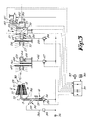
- the working of the device can be easily derived from fig. 1.
- the weaver removes the empty sleeve 12 and places a new bobbin 2 on the bobbin support 1. Further, the working is analogous if the previous bobbin 2 is empty and a break occurs at the height of the bobbin 2 in question.
- the end of yarn 5 is presented either manually or automatically to the top 4 of the bobbin support 1, whereas the suction means 32 are activated by opening the valve 35. It is possible to check whether the end of yarn 5 is situated far enough in the thread guide duct 3 by means of a built-in thread detector 36 which may, for example, transmit a signal to an indicator 37 by means of the above-mentioned control unit 31.
- blow means 6 and the suction and blow device 9 are excited simultaneously, either by activating the push button 30, or automatically by means of the control unit 31, such that the valves 28 and 29 open up.
- the end of yarn 5 is catapulted out of the thread guide duct 3 so to speak, to be conveyed by the suction and blow action of the suction and blow device 9 into the winding tube 16.
- the arrival of the thread can hereby be detected by means of the thread detector 20.
- fig. 1 shows a possibility, in particular in which a method and device as known from US patent 4.832.091 are being applied.
- the winding tube 16 is put in a particular position by means of the motor 17, the angle detector 21 and the control unit 31, such that the far end of the winding tube 16 is placed in front of a suction element 40 presented to the prewinder 7.
- the end of yarn automatically finds its way to this suction element 40.
- a second suction element 41 the thread remainder 39 is taken up, after which the end of yarn 5, which stretches out into the second suction element 41 at that moment, is connected to the thread remainder 39 by means of a connecting device 42, such as a tying-in device or a tool to form a splice.
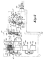
- Fig. 3 shows a variant whereby an extra suction and blow device 43 has been mounted in between the bobbin support 1 and the prewinder 7, also composed of a continuous duct 44 and a duct 45 ending slantways in it, whereby the latter has been provided with a compressed air connection 46 in which an electrically controlled valve 47 has been applied.
- a guide plate 49 analogous to the guide plate 26, has been applied at the entry 48 of the suction and blow device 43, and possibly also a thread eye 50.
- the working can be easily derived from fig. 3.
- the difference with the embodiment shown in fig. 1 lies in that larger distances can be bridged, and that, when the valves 28 and 29 are switched on, the valve 47 is also switched on.
- Figs. 4 and 5 show how, in the case where several yarn supply ducts have been provided for, the above-mentioned parts can be mounted and combined into, for example, a bobbinstand 51 on wheels, the frame 52 of which is represented separately in fig.6 for clarity's sake.
- the frame 52 hereby has a number of supporting bars 53, 54 and 55-56 which, as shown in fig. 5, are respectively designed for the mounting of the bobbin supports 1, the suction and blow devices 43 and the prewinders 7, as well as a supporting bar 57 upon which a number of bobbin supports have been mounted, upon which reserve thread bobbins 58 can be provided.
- the prewinders 7, the suction and blow devices 43 as well as the bobbin supports 1 form a separate bobbinstand 51, which can be partly presented over the weaving machine 59, such that the weft threads 23 find their way to the main nozzles 60, it is also possible, according to a variant, that one, several or all of these parts are mounted fixedly onto the weaving machine 59.
- the valves 28 and 35 have been built in in junction pieces 61 mounted on the supporting bar 53.
- the valves 47 and 29 are situated immediately next to the suction and blow devices 9 and 43 in question, and are attached onto the supporting bars 54, 55 and 56.
- the supporting bars 53-56 are made hollow and are connected onto the compressed air source 15, as is schematically represented in fig. 6. This makes it possible, as shown in fig. 5, to supply all the above-mentioned valves with compressed air by means of very short pipes 62, which offers the advantage that said pipes 62 cannot form any hindrance to the transport of the weft threads 23.
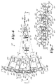
- these bobbins are in preference arranged according to a configuration as shown in fig. 7, where the different bobbins have been separately marked with references 2A to 2F for clarity's sake.
- the bobbins are arranged in two rows, one situated on top of the other.
- the bobbin supports 1 are preferably mounted horizontally in order to avoid dust accumulation on the head faces 63 of the bobbins 2A-2F.
- the bobbin supports 1 are preferably moveable, such that the bobbins 2A-2F can be moved between a position A from which the weft thread 23 can be unspooled, and a position B in which the bobbin 2A-2F in question can be easily reached in order to place another bobbin or in order to present the end of yarn 5 to the top 4 of the bobbin support 1. In this position B, the end of yarn 23 is taken up in the bobbin support 1.
- the bobbin supports 1 are therefore part of rotatable stands 64 which, as shown in fig. 7, are alternately situated above and under the junction pieces 61.
- each stand 64 when viewed from above, is preferably L-shaped, whereby the stand 64 can be rotated at one far end of this L-shape into one of the above-mentioned junction pieces 61 by means of a vertical pivot 70.
- each bobbin support 1 has a horizontal part 71 and a vertical part 72, whereby the vertical part 72 is connected to the pivot 70 by means of a horizontal arm 73.
- the bottommost end of the part 72 hereby works in conjunction with a second junction piece 61 which is situated at a certain distance from the junction piece 61 in which the pivot 70 of the bobbin 2 in question is mounted.
- the whole has first switch means 74 which switch on the suction means 32 when the bobbin support 1 in question is in position B.
- These switch means 74 are formed, as indicated in figs. 9 to 11, as the above-mentioned valve 35 has been built in in the pivot 70 and is therefore connected to the thread guide duct 3 via a duct 75 through the horizontal arm 73.
- the duct 75 ends slantways in the thread guide duct 3, such that blow air supplied via this way can escape via the far end 13, as a result of which a suction movement is created at the top 4.
- the valve 35 is formed by an entry 76 stretching radially out through the junction piece 61 with respect to the pivot 70, and a duct 77 coming out in the side wall of the pivot 70, in which the above-mentioned duct 75 comes out, such that in position A the situation is as shown in fig. 11.
- the construction has second switch means 78 which prevent that a blow movement can be provided for in the thread guide duct 3 as long as the bobbin support 1 in question is not in position A.
- these second switch means 78 are preferably made up of a fixed exit 79 for the compressed air, connected to the valve 28 and an entry 80, communicating with the thread guide duct 3, in particular with the far end of the part 72, which, in said position A, is situated opposite the exit 79.
- the stand 64 is equipped with a stop 81 which makes contact with the side wall of any of the junction piece 61, and which can possibly be held against it by means of a permanent magnet 82 or another locking mechanism.
- a stop 81 which makes contact with the side wall of any of the junction piece 61, and which can possibly be held against it by means of a permanent magnet 82 or another locking mechanism.
Landscapes
- Engineering & Computer Science (AREA)
- Textile Engineering (AREA)
- Looms (AREA)
- Replacing, Conveying, And Pick-Finding For Filamentary Materials (AREA)
Description
- This invention concerns a device for the supply of weft threads in weaving machines.
- In particular, the invention concerns a device which allows the end of yarn of the weft thread of a bobbin to be automatically carried to the entry of a prewinder situated at some distance, without the intervention of complicated mechanisms being required to grip and convey this end of yarn.
- To this aim, the present invention concerns a device for the supply of weft threads in weaving machines, characterized in that it is made up of a combination of at least one bobbin support over which it is possible to slip a bobbin; a thread guide duct which stretches out axially through the bobbin support and which gives out into the environment at the top of the bobbin support, to which the end of yarn of a bobbin can be supplied; blow means which can work in conjunction with the thread guide duct, providing an airstream towards the top of the bobbin support; a prewinder; a suction and blow device mounted at the entry of the prewinder; and means which make it possible that at least the blow means that can work in conjunction with the thread guide duct as well as the blow and suction device at the entry of the prewinder can be switched on simultaneously, such that an airstream is created, as a result of which the end of yarn of a bobbin situated in the thread guide duct is carried to the prewinder.
- As the end of yarn of a bobbin placed on the aforesaid bobbin support is blown towards the prewinder from a central position with respect to this bobbin, the end of yarn will be conveyed very evenly and in the shape of a loop, whereby this loop will also unroll evenly, which offers the advantage that the weft thread will be carried to the desired place with great certainty.
- In a preferred embodiment, an extra suction and blow device has been mounted in between said bobbin support and prewinder, such that relatively large distances can be bridged by the weft thread.
- In order to assure an optimum guidance of the end of yarn which is moved by the airstream, guide plates for the airstream are preferably mounted at the entries of said suction and blow devices, made in the shape of flat discs having a central passage.
- According to a preferred embodiment, the device is built such that the bobbin supports can be easily reached by the weaver, such that it is relatively easy to place a new bobbin, and such that the end of yarn can be sucked up relatively easily in the bobbin support.
- In order to better explain the characteristics of the invention, by way of example only and without being limitative in any way, the following preferred embodiments are described with reference to the accompanying drawings where:
- fig. 1 is a schematic representation of the device according to the invention;
- fig. 2 shows a view according to arrow F2 in fig. 1;
- fig. 3 shows a variant of the device according to the invention;
- fig. 4 shows a view from above of a practical embodiment according to the invention;
- fig. 5 is a cross-section according to line V-V in fig. 4, whereby the frame of the device is represented only schematically for the sake of clarity;
- fig. 6 shows a practical embodiment of the frame that can be used in the configuration according to fig. 5;
- fig. 7 shows a view according to line VII-VII in fig. 4;
- fig. 8 shows a part of the device in perspective, in particular the part indicated in fig. 4 by F8;
- fig. 9 is a cross-section according to line IX-IX in fig. 8;
- figs. 10 and 11 are cross-sections according to lines X-X and XI-XI respectively in fig. 9;
- fig. 12 shows a view according to arrow F12 in fig. 9;
- fig. 13 shows the part indicated in fig. 9 by F13, but for another position.
- As indicated in fig. 1, the device according to the invention consists essentially of at least one
bobbin support 1 over which it is possible to slip abobbin 2; athread guide duct 3 which stretches out axially through thebobbin support 1 and which gives out into the environment at the top 4 of thebobbin support 1, to which the end ofyarn 5 of abobbin 2 can be supplied;blow means 6 which can work in conjunction with thethread guide duct 3, providing an airstream towards the top 4 of the bobbin support; aprewinder 7 and a suction and blow device 9 mounted at theentry 8 of theprewinder 7. At the top 4, the exit of thethread guide duct 3 is directed precisely towards theentry 10 of the suction and blow device 9. - The
bobbin support 1 is tube-shaped. Abobbin 2 is mounted on thebobbin support 1 by sliding it over the latter from the top 4, whereby thebobbin 2 is clamped in the known way by means ofclamping elements 11 mounted on thebobbin support 1 and which work in conjunction with thesleeve 12 of thebobbin 2. - The above-mentioned blow means 6 which can work in conjunction with the
thread guide duct 3 are in preference composed of a nozzle, provided at the farend 13 situated opposite the top 4, and connected onto acompressed air source 15 via acompressed air connection 14. - The
prewinder 7 consists of, as is known, awinding tube 16 driven by means of amotor 17 on the one hand, and afixed accumulator drum 18 on the other hand. Thewinding tube 16 may contain athread brake 19, as well as athread detector 20. In order to check the angle position of thewinding tube 16, use can be made of anangle detector 21 or something similar. - The above-mentioned suction and blow device 9 consists of a jet nozzle formed by a
continuous duct 22 for the guidance of aweft thread 23 and at least oneduct 24 which ends in it slantways and which has been provided with acompressed air connection 25 onto thecompressed air source 15, such that, on the one hand, a sucking action is created at theentry 10, while, on the other hand, air is blown into thewinding tube 16. - In preference, a
guide plate 26 is mounted at theentry 10 of the suction and blow device 9 to guide the sucked-up air, such that an end ofyarn 5 presented at theguide plate 26 automatically moves in the direction of the suction and blow device 9. Theguide plate 26 preferably has a circle-shaped section in which acentral opening 27 has been formed, as shown in fig. 2. - The construction as a whole contains means which make it possible to simultaneously switch on the blow means 6 and the suction and blow device 9. In the embodiment according to fig. 1, these are composed of electrically controlled,
pneumatic valves compressed air connections push button 30, or which are automatically controlled by means of acontrol unit 31. - In preference, the device is also provided with suction means 32 which work in conjunction with the
bobbin support 1, such that, at the top 4, the end ofyarn 5 can be sucked up. These suction means 32 consist of, for example, at least oneduct 33 ending slantways in thethread guide duct 3, which, by means of acompressed air connection 34, can be fed by the compressed air source via a mechanically operatedvalve 35. - The working of the device can be easily derived from fig. 1. In case the
previous bobbin 2 is empty, the weaver removes theempty sleeve 12 and places anew bobbin 2 on thebobbin support 1. Further, the working is analogous if theprevious bobbin 2 is empty and a break occurs at the height of thebobbin 2 in question. The end ofyarn 5 is presented either manually or automatically to the top 4 of thebobbin support 1, whereas the suction means 32 are activated by opening thevalve 35. It is possible to check whether the end ofyarn 5 is situated far enough in thethread guide duct 3 by means of a built-inthread detector 36 which may, for example, transmit a signal to anindicator 37 by means of the above-mentionedcontrol unit 31. - Further, the blow means 6 and the suction and blow device 9 are excited simultaneously, either by activating the
push button 30, or automatically by means of thecontrol unit 31, such that thevalves yarn 5 is catapulted out of thethread guide duct 3 so to speak, to be conveyed by the suction and blow action of the suction and blow device 9 into thewinding tube 16. The arrival of the thread can hereby be detected by means of thethread detector 20. Of course, attention is paid to it, for example by means of thecontrol unit 31, that thethread brake 19 which has possibly been provided is put in open position. - It is important that the end of
yarn 5 is blown away from a central position with regard to thebobbin 2, as this offers the advantage that the relativelyshort loop 38 moves and unrolls very evenly, as a result of which theweft thread 23 will move in the direction of theprewinder 7 with great certainty. - After the end of
yarn 5 has found its way to thewinding tube 16, it can be further processed in various ways. For example, it is possible to connect this end of yarn to athread remainder 39 on theaccumulator drum 18. Although the further treatment of the ends ofyarn 5 does not fall within the scope of the present invention, fig. 1 shows a possibility, in particular in which a method and device as known from US patent 4.832.091 are being applied. Hereby, preliminary to the threading, thewinding tube 16 is put in a particular position by means of themotor 17, theangle detector 21 and thecontrol unit 31, such that the far end of thewinding tube 16 is placed in front of asuction element 40 presented to theprewinder 7. - When said threading is executed, the end of yarn automatically finds its way to this
suction element 40. By means of asecond suction element 41, thethread remainder 39 is taken up, after which the end ofyarn 5, which stretches out into thesecond suction element 41 at that moment, is connected to thethread remainder 39 by means of a connectingdevice 42, such as a tying-in device or a tool to form a splice. - Fig. 3 shows a variant whereby an extra suction and
blow device 43 has been mounted in between thebobbin support 1 and theprewinder 7, also composed of acontinuous duct 44 and aduct 45 ending slantways in it, whereby the latter has been provided with acompressed air connection 46 in which an electrically controlledvalve 47 has been applied. - A
guide plate 49, analogous to theguide plate 26, has been applied at theentry 48 of the suction andblow device 43, and possibly also athread eye 50. - The working can be easily derived from fig. 3. The difference with the embodiment shown in fig. 1 lies in that larger distances can be bridged, and that, when the
valves valve 47 is also switched on. - Figs. 4 and 5 show how, in the case where several yarn supply ducts have been provided for, the above-mentioned parts can be mounted and combined into, for example, a
bobbinstand 51 on wheels, theframe 52 of which is represented separately in fig.6 for clarity's sake. Theframe 52 hereby has a number of supportingbars blow devices 43 and theprewinders 7, as well as a supportingbar 57 upon which a number of bobbin supports have been mounted, upon whichreserve thread bobbins 58 can be provided. Although, as indicated in fig. 5, theprewinders 7, the suction andblow devices 43 as well as the bobbin supports 1 form aseparate bobbinstand 51, which can be partly presented over theweaving machine 59, such that theweft threads 23 find their way to themain nozzles 60, it is also possible, according to a variant, that one, several or all of these parts are mounted fixedly onto theweaving machine 59. - The
valves junction pieces 61 mounted on the supportingbar 53. Thevalves blow devices 9 and 43 in question, and are attached onto the supportingbars compressed air source 15, as is schematically represented in fig. 6. This makes it possible, as shown in fig. 5, to supply all the above-mentioned valves with compressed air by means of veryshort pipes 62, which offers the advantage that saidpipes 62 cannot form any hindrance to the transport of theweft threads 23. - It is obvious that the control of the different parts is carried out as shown in fig. 3. For clarity's sake, the connections to the
control unit 31 are not shown in figs. 4 and 5. - If several bobbins are implied, these bobbins are in preference arranged according to a configuration as shown in fig. 7, where the different bobbins have been separately marked with
references 2A to 2F for clarity's sake. Hereby, the bobbins are arranged in two rows, one situated on top of the other. - As shown in fig. 5, the bobbin supports 1 are preferably mounted horizontally in order to avoid dust accumulation on the head faces 63 of the
bobbins 2A-2F. - As shown in fig. 4, the bobbin supports 1 are preferably moveable, such that the
bobbins 2A-2F can be moved between a position A from which theweft thread 23 can be unspooled, and a position B in which thebobbin 2A-2F in question can be easily reached in order to place another bobbin or in order to present the end ofyarn 5 to the top 4 of thebobbin support 1. In this position B, the end ofyarn 23 is taken up in thebobbin support 1. In preference, the bobbin supports 1 are therefore part of rotatable stands 64 which, as shown in fig. 7, are alternately situated above and under thejunction pieces 61. -
Vertical partitions 65 andhorizontal partitions 66 have been applied in between thebobbins 2A-2F so as to avoid that dust is carried from one bobbin to the other, and so as to avoid too large a balloon formation during the unspooling. In order to keep the whole as compact as possible, and to nevertheless enable thebobbins 2A-2F to welter easily from their position A into position B, bobbin supports 1, as shown in the view from above, have been arranged according to adirection 67 at angle with the connectingline 68 between the centre of thebobbin 2A-2F in question and thethread removal point 69 situated downstream to theprewinder 7, whereby thebobbin support 1 and thebobbin 2A-2F placed on it are closer to the one adjacentvertical partition 65 than to the otheradjacent partition 65. - It is clear that said arrangement of the
bobbins 2 has for a result that theweft threads 23 are merely bent over small angles X, Y and Z as they are carried to theirthread removal point 69. - As shown in particular in fig. 8, each stand 64, when viewed from above, is preferably L-shaped, whereby the
stand 64 can be rotated at one far end of this L-shape into one of the above-mentionedjunction pieces 61 by means of avertical pivot 70. Hereby, eachbobbin support 1 has ahorizontal part 71 and avertical part 72, whereby thevertical part 72 is connected to thepivot 70 by means of ahorizontal arm 73. The bottommost end of thepart 72 hereby works in conjunction with asecond junction piece 61 which is situated at a certain distance from thejunction piece 61 in which thepivot 70 of thebobbin 2 in question is mounted. - The whole has first switch means 74 which switch on the suction means 32 when the
bobbin support 1 in question is in position B. These switch means 74 are formed, as indicated in figs. 9 to 11, as the above-mentionedvalve 35 has been built in in thepivot 70 and is therefore connected to thethread guide duct 3 via aduct 75 through thehorizontal arm 73. Theduct 75 ends slantways in thethread guide duct 3, such that blow air supplied via this way can escape via thefar end 13, as a result of which a suction movement is created at the top 4. - The
valve 35 is formed by anentry 76 stretching radially out through thejunction piece 61 with respect to thepivot 70, and aduct 77 coming out in the side wall of thepivot 70, in which the above-mentionedduct 75 comes out, such that in position A the situation is as shown in fig. 11. - Further, the construction has second switch means 78 which prevent that a blow movement can be provided for in the
thread guide duct 3 as long as thebobbin support 1 in question is not in position A. - As shown in figs. 9 and 12, these second switch means 78 are preferably made up of a fixed
exit 79 for the compressed air, connected to thevalve 28 and anentry 80, communicating with thethread guide duct 3, in particular with the far end of thepart 72, which, in said position A, is situated opposite theexit 79. - The
stand 64 is equipped with astop 81 which makes contact with the side wall of any of thejunction piece 61, and which can possibly be held against it by means of apermanent magnet 82 or another locking mechanism. When thestand 64 is turned back, theentry 80 moves away from theexit 79 and the above-mentionedvalve 35 finally moves into a position as indicated in fig. 13. From that moment on, compressed air is blown through theduct 75 to thefar end 13, such that a suction movement is created at the top 4. A yarn supplied by the weaver at the top 4 of the bobbin support will then also be sucked up automatically, whereby anindicator 37 lights up as soon as said yarn reaches thethread detector 36. Consequently, thestand 64 rotates back into position A, after which the above-mentioned valves, required for the conveyance of the yarn into theprewinder 7, can be excited.
Claims (22)
- Device for the supply of weft threads in weaving machines, characterized in that it consists of the combination of at least one bobbin support (1) over which it is possible to slip a bobbin (2); a thread guide duct (3) which stretches out axially through the bobbin support (1) and which gives out into the environment at the top (4) of the bobbin support (1) to which the end of yarn (5) of a bobbin (2) can be supplied; blow means (6) which can work in conjunction with the thread guide duct (3), providing an airstream towards the top of the bobbin support (1); a prewinder (7); a suction and blow device (9) mounted at the entry of the prewinder (7); and means which make it possible that at least said blow means (6) and said suction and blow device (9) can be switched on simultaneously, such that an airstream is created, as a result of which the end of yarn (5) of a bobbin (2) situated in the thread guide duct (3) is carried to the prewinder (7).
- Device according to claim 1, characterized in that the thread guide duct (3) near the top (4) of the bobbin support (1) is directed towards the entry (10) of the suction and blow device (9) situated in front of the prewinder (7).
- Device according to claim 1 or 2, characterized in that the means for simultaneously switching on the blow means (6) which work in conjunction with the thread guide duct (3) and the suction and blow device (9) situated in front of the prewinder (7) are composed of valves (28,29) connected to a compressed air source (15) and a common push button (30) to operate said valves.
- Device according to claim 1 or 2, characterized in that an extra suction and blow device (43) has been provided between the bobbin support (1) and the prewinder (7).
- Device according to claim 4, characterized in that the entry (48) of the intermediate suction and blow device (43) is mainly an extension of the thread guide duct (3) situated in the bobbin support (1).
- Device according to claim 4 or 5, characterized in that the entry (10) of the suction and blow device (9) situated at the entry of the prewinder (7) is positioned as an extension of the exit of the intermediate suction and blow device (43).
- Device according to any of claims 4 to 6, characterized in that it has means which make it possible to simultaneously switch on the blow means (6) at the bobbin support (1), the suction and blow device (9) at the entry of the prewinder (7) as well as the intermediate suction and blow device (43).
- Device according to claim 7, characterized in that the means for simultaneously switching on said elements mainly consist of valves (28,29,47) which are connected to a compressed ain source (15) and a common push button (30) to operate said valves.
- Device according to any of claims 4 to 8, characterized in that a guide plate (49) is mounted immediately in front of the intermediate suction and blow device (43).
- Device according to any of the above claims, characterized in that a guide plate (26) is mounted in front of the entry of the suction and blow device (9) which is situated at the prewinder (7).
- Device according to claim 9 or 10, characterized in that the guide plate (26,49) is made up of a flat, circle-shaped plate with a central opening (27).
- Device according to any of the above claims, characterized in that the bobbin support (1) is equipped with suction means (32).
- Device according to claim 12, characterized in that the bobbin support (1) can be moved between a position (A) from which the bobbin (2) can be unspooled and a position (B) which allows for the end of yarn (5) to be presented to the top (4) of a bobbin support (1) respectively, whereby it has first switch means (74) which automatically provide a suction movement as soon as the bobbin support (1) is placed in said second position (B).
- Device according to claim 13, characterized in that it is equipped with two switch means (78) which make it impossible for the blow means (6) to provide an airstream in the thread guide duct (3) when the bobbin support (1) is in a position different from the position (A) from where the weft thread (23) is unspooled.
- Device according to claim 12, 13 or 14, characterized in that a thread detector (36) has been applied in the thread guide duct (3) to check the presence of a sucked-up end of yarn (5).
- Device according to any of claims 13, 14 or 15, characterized in that the bobbin support (1) can rotate around a pivot (70), and that the first switch means (74) consist of a duct (77) giving out into the side wall of the pivot (70), an entry (76) connected to a compressed air source (15) giving out into the side wall of the seating of the pivot (70), and a duct (75) which, from the first duct (77), forms a connection with the thread guide duct (3), whereby the duct (77) which gives out into the side wall of the pivot (70) can only be put out of its normal position opposite the entry (76) by turning the bobbin support (1), and whereby the duct (75) which connects the pivot (70) to the thread guide duct (3) gives out at angle in the thread guide duct (3) according to a direction such that a suction movement is created at the top (4) of the bobbin support (1).
- Device according to any of claims 12 to 16, characterized in that the device has second switch means (78) which prevent that a blow movement can be provided for at the top of the bobbin support (1) when the bobbin support (1) is removed from its normal position (A), whereby these second switch means (78) are mainly composed of a fixed exit (79) for the compressed air; an entry (80) communicating with the thread guide duct (3), which in the normal position of the bobbin support (1) is situated opposite the above-mentioned exit (79), such that when the bobbin support (1) is removed, the entry (80) is placed next to the exit (79); and a stop (81) which allows for an exact positioning between the exit (79) and the entry (80).
- Device according to any of claims 14 to 17, characterized in that it has several bobbin supports (1); that these bobbin supports are arranged according to at least two rows situated one on top of the other; that the above-mentioned first gnd second switch means (74,78) are built in in junction pieces (61) arranged at certain distances, whereby one and the same junction piece (61) is equipped both with first and with second switch means (74,78); that each bobbin support (1) is part of an L-shaped stand (64) which can rotate in a horizontal field by means of a pivot (70) in a junction piece (61), whereby this stand (64), in the position (A) of the bobbin support (1) whereby a weft thread can be unspooled, also makes contact with a second, adjacent junction piece (61); and that for each bobbin support the first switch means are situated in the junction piece (61) in which said pivot (70) is placed, whereas the second switch means (78) are situated in the aforesaid adjacent junction piece (61).
- Device according to claim 18, characterized in that the above-mentioned rotatable stands (64) for the respective bobbins (2A-2F) are alternately situated above and under the junction piece (61).
- Device according to any of the above claims, characterized in that the compressed air supply for the different operations goes via pipes (62) which are connected to hollow supporting bars (53-56) which communicate with a compressed air source (15).
- Device according to any of the above claims, characterized in that each bobbin support (1) is positioned precisely horizontally.
- Device according to any of the above claims, in particular in which use is made of several bobbin supports (1), characterized in that partitions (65,66) are mounted in between the respective bobbin supports (1) and the bobbins (2A-2F) which are possibly placed upon them.
Applications Claiming Priority (2)
| Application Number | Priority Date | Filing Date | Title |
|---|---|---|---|
| BE8901055A BE1008048A3 (en) | 1989-10-04 | 1989-10-04 | Device for supplying weft thread in weaving machines. |
| BE8901055 | 1989-10-04 |
Publications (2)
| Publication Number | Publication Date |
|---|---|
| EP0421518A1 EP0421518A1 (en) | 1991-04-10 |
| EP0421518B1 true EP0421518B1 (en) | 1994-02-02 |
Family
ID=3884328
Family Applications (1)
| Application Number | Title | Priority Date | Filing Date |
|---|---|---|---|
| EP90202547A Expired - Lifetime EP0421518B1 (en) | 1989-10-04 | 1990-09-26 | Device for the supply of weft threads in weaving machines |
Country Status (4)
| Country | Link |
|---|---|
| US (1) | US5107905A (en) |
| EP (1) | EP0421518B1 (en) |
| BE (1) | BE1008048A3 (en) |
| DE (1) | DE69006443T2 (en) |
Families Citing this family (2)
| Publication number | Priority date | Publication date | Assignee | Title |
|---|---|---|---|---|
| US5329962A (en) * | 1991-09-03 | 1994-07-19 | Nissan Motor Co., Ltd. | Weft supply changing and threading apparatus |
| IT1265071B1 (en) * | 1993-05-18 | 1996-10-30 | Nuovo Pignone Spa | DEVICE FOR CONTINUOUS ADJUSTMENT OF THE KEY SENSITIVITY, IN THE WEFT INSERTION CONTROL IN A TEXTILE FRAME |
Family Cites Families (5)
| Publication number | Priority date | Publication date | Assignee | Title |
|---|---|---|---|---|
| US3180368A (en) * | 1962-01-23 | 1965-04-27 | Prince Jidosha Kogyo Kabushiki | Device for projecting weft yarns in fluid jet type shuttleless loom |
| FR1344809A (en) * | 1962-01-23 | 1963-11-29 | Prince Jidosha Kogyo Kabushiki | Device for projecting weft threads in a fluid jet type shuttle-less loom |
| JPS5777174A (en) * | 1980-10-31 | 1982-05-14 | Kuraray Co Ltd | Winder magazine |
| NL8602724A (en) * | 1986-10-29 | 1988-05-16 | Picanol Nv | METHOD AND APPARATUS FOR RESTORING THE WIRE FEED IN WEAVING MACHINES IN THE INTERRUPTION BETWEEN THE BOBBIN AND THE WIRE STOCK. |
| US4969489A (en) * | 1988-07-14 | 1990-11-13 | Nissan Motor Co., Ltd. | Weft threading system for fluid jet loom using the storage drum winding arm |
-
1989
- 1989-10-04 BE BE8901055A patent/BE1008048A3/en not_active IP Right Cessation
-
1990
- 1990-09-26 EP EP90202547A patent/EP0421518B1/en not_active Expired - Lifetime
- 1990-09-26 DE DE90202547T patent/DE69006443T2/en not_active Expired - Fee Related
- 1990-10-04 US US07/592,524 patent/US5107905A/en not_active Expired - Fee Related
Also Published As
| Publication number | Publication date |
|---|---|
| US5107905A (en) | 1992-04-28 |
| EP0421518A1 (en) | 1991-04-10 |
| DE69006443D1 (en) | 1994-03-17 |
| DE69006443T2 (en) | 1994-05-11 |
| BE1008048A3 (en) | 1996-01-03 |
Similar Documents
| Publication | Publication Date | Title |
|---|---|---|
| JPH03206155A (en) | Dust removing device in weaving machine | |
| JP2023539939A (en) | thread handling system | |
| ITMI940578A1 (en) | OPEN-END FILATOIO PRODUCING CROSSED COILS | |
| EP0269140B1 (en) | Method and mechanism for repairing the weft supply on weaving machines in case of an interruption between the supply package and the weft accumulator | |
| US5293739A (en) | Method and apparatus for supplying a sliver to a spinning position of a spinning machine | |
| EP0421518A1 (en) | Device for the supply of weft threads in weaving machines | |
| US5396758A (en) | Method of respinning-in on open-end spinning machines and a device for carrying out the method | |
| JP3720911B2 (en) | Thread end search device | |
| US4998566A (en) | Liquid warp splicing system for a warp in a loom | |
| US4951718A (en) | Repair of broken weft threads using plural yarn supply packages | |
| US5105855A (en) | Apparatus and method for clearing a warp yarn break in a loom | |
| US5016680A (en) | Weft processing and releasing apparatus in a jet loom | |
| EP0291486B1 (en) | Method for threading a pick insertion device on weaving machines and a device which uses this method | |
| ITMI960509A1 (en) | DEVICE FOR DETACHING THE END OF THE THREAD FROM THE SURFACE OF A SPOOL | |
| US5526634A (en) | Robot device for piled-package type double twister | |
| US5485967A (en) | Yarn winding apparatus with manifold assembly movable between blowing and standby positions relative to a pair of bobbin carrying spindles | |
| EP0310690A1 (en) | Process for splicing fibres in strips, and a machine for feeding a textile machine incorporating such a process | |
| KR100231524B1 (en) | Actual storage and supply | |
| US5772137A (en) | Yarn monitor for automatic cross winding and assembly machines | |
| JP2584991Y2 (en) | Yarn feed processing equipment in jet looms | |
| JPH02277853A (en) | Weft feeding apparatus for loom without shuttle | |
| EP0311169B1 (en) | Method for positioning of auxiliary mechanisms for weaving machines, and a device which uses this method | |
| JP3319091B2 (en) | Yarn supply processing method in jet loom | |
| JPH086060Y2 (en) | Yarn supply processing equipment in jet loom | |
| JPH0738293Y2 (en) | Relay pipe of the yarn spinning machine |
Legal Events
| Date | Code | Title | Description |
|---|---|---|---|
| PUAI | Public reference made under article 153(3) epc to a published international application that has entered the european phase |
Free format text: ORIGINAL CODE: 0009012 |
|
| AK | Designated contracting states |
Kind code of ref document: A1 Designated state(s): CH DE FR GB IT LI |
|
| 17P | Request for examination filed |
Effective date: 19910528 |
|
| 17Q | First examination report despatched |
Effective date: 19930507 |
|
| GRAA | (expected) grant |
Free format text: ORIGINAL CODE: 0009210 |
|
| AK | Designated contracting states |
Kind code of ref document: B1 Designated state(s): CH DE FR GB IT LI |
|
| PG25 | Lapsed in a contracting state [announced via postgrant information from national office to epo] |
Ref country code: FR Effective date: 19940202 |
|
| ITF | It: translation for a ep patent filed | ||
| REF | Corresponds to: |
Ref document number: 69006443 Country of ref document: DE Date of ref document: 19940317 |
|
| EN | Fr: translation not filed | ||
| PG25 | Lapsed in a contracting state [announced via postgrant information from national office to epo] |
Ref country code: GB Effective date: 19940926 |
|
| PLBE | No opposition filed within time limit |
Free format text: ORIGINAL CODE: 0009261 |
|
| STAA | Information on the status of an ep patent application or granted ep patent |
Free format text: STATUS: NO OPPOSITION FILED WITHIN TIME LIMIT |
|
| 26N | No opposition filed | ||
| GBPC | Gb: european patent ceased through non-payment of renewal fee |
Effective date: 19940926 |
|
| PGFP | Annual fee paid to national office [announced via postgrant information from national office to epo] |
Ref country code: DE Payment date: 19970905 Year of fee payment: 8 |
|
| PGFP | Annual fee paid to national office [announced via postgrant information from national office to epo] |
Ref country code: CH Payment date: 19971204 Year of fee payment: 8 |
|
| PG25 | Lapsed in a contracting state [announced via postgrant information from national office to epo] |
Ref country code: LI Free format text: LAPSE BECAUSE OF NON-PAYMENT OF DUE FEES Effective date: 19980930 Ref country code: CH Free format text: LAPSE BECAUSE OF NON-PAYMENT OF DUE FEES Effective date: 19980930 |
|
| REG | Reference to a national code |
Ref country code: CH Ref legal event code: PL |
|
| PG25 | Lapsed in a contracting state [announced via postgrant information from national office to epo] |
Ref country code: DE Free format text: LAPSE BECAUSE OF NON-PAYMENT OF DUE FEES Effective date: 19990701 |
|
| PG25 | Lapsed in a contracting state [announced via postgrant information from national office to epo] |
Ref country code: IT Free format text: LAPSE BECAUSE OF NON-PAYMENT OF DUE FEES;WARNING: LAPSES OF ITALIAN PATENTS WITH EFFECTIVE DATE BEFORE 2007 MAY HAVE OCCURRED AT ANY TIME BEFORE 2007. THE CORRECT EFFECTIVE DATE MAY BE DIFFERENT FROM THE ONE RECORDED. Effective date: 20050926 |