EP0421165A1 - Method for taring a conveyor-type dispensing scale - Google Patents
Method for taring a conveyor-type dispensing scale Download PDFInfo
- Publication number
- EP0421165A1 EP0421165A1 EP90117617A EP90117617A EP0421165A1 EP 0421165 A1 EP0421165 A1 EP 0421165A1 EP 90117617 A EP90117617 A EP 90117617A EP 90117617 A EP90117617 A EP 90117617A EP 0421165 A1 EP0421165 A1 EP 0421165A1
- Authority
- EP
- European Patent Office
- Prior art keywords
- belt
- weighing
- taring
- signals
- band
- Prior art date
- Legal status (The legal status is an assumption and is not a legal conclusion. Google has not performed a legal analysis and makes no representation as to the accuracy of the status listed.)
- Granted
Links
Images
Classifications
-
- G—PHYSICS
- G01—MEASURING; TESTING
- G01G—WEIGHING
- G01G11/00—Apparatus for weighing a continuous stream of material during flow; Conveyor belt weighers
- G01G11/006—Special taring or checking devices therefor
Definitions
- the invention relates to a method for taring a dosing belt weigher with continuous dosing, in which a weighing signal generated by a load cell and a belt circulation signal generated by a sensor device are fed to a taring device, which detects the weighing signal in sections and corrects them for the local band influence assigned to each section of the band.
- Belt weighers are special belt conveyors with which bulk goods can be added to a process with an adjustable conveying force.
- the load and the speed of the belt are measured to determine the conveying strength.
- the product of the net belt load and the belt speed corresponds to the delivery rate that is to be metered and thus controlled.
- the belt load measured as a weighing signal is made up of the proportion of the bulk material, the belt loading, and the belt influence resulting from the weight and the deformation forces of the belt. If you consider a complete band circulation, the band influence can be averaged over it and the band load signal can be corrected by this mean value.
- the belt load corresponding to the bulk material on the belt per belt circulation is then obtained as a net value.
- a constant metering ie a constant delivery rate at the discharge edge of the belt, which is caused by a correction of the belt related to the number of belt revolutions flow can not be achieved, since the influence of the band is only constant on average, but is subject to considerable fluctuations during a band circulation.
- the band influence quantities determined in sections are subtracted from the weighing signals determined for the corresponding sections so that a net band load signal reduced by the local band influence is obtained for each band section.
- the object of the invention is to provide a method for taring a dosing belt scale of the type mentioned at the outset, which detects the changing belt influence during the continuous weighing process and takes it into account in the correction.
- the taring device forms a mean value from the weighing signals of a statistically relevant number of belt revolutions, which is compared with the mean values associated with the individual belt sections and formed from the weighing signals of these belt revolutions accumulated in sections Difference values tare signals for correcting the local band influence of the following band circulation are formed.
- the method according to the invention is based on the fact that the belt loading and the belt influence differ significantly in their statistical behavior.
- the band influence is location-dependent and, due to the physical nature of its influencing variables, is subject to slow changes over time, so it forms a quasi-stationary signal.
- the fluctuations of the belt loading with dosing material have a purely stochastic character and are therefore constant in their mean value when viewed over several belt revolutions in each belt section.
- the local band influencing variables can therefore be filtered out of the weighing signal and used for taring the band influence in sections. Slow changes in the band influence over time are thus recorded and taken into account in taring.
- the method according to the invention thus enables high metering accuracy in sections, which is not impaired by changes in the influence of the band.
- the mean value of the summed up weighing signals of the belt circulation are subtracted from the weighing signals of a belt circulation recorded by the belt section, and that a statistically relevant number of belt revolutions in sections is recorded from the difference values thus formed Average values serving as a tare signal are formed.
- Such processing of the weighing signals enables a simple construction of the taring device.
- the weighing signals processed by the taring device are reduced by the average band influencing variable determined when the band is unloaded. At the beginning of a continuous weighing process, the dosing belt scale is tared in the unloaded state in such a way that the average of the weighing signals already corresponds to the average net belt load.
- FIG. 1 the basic structure of a weigh feeder 1 is shown.
- a belt 2 rotating around two drums takes a feed 4 from a feed hopper 3 and feeds it to a process container 5 at a metered delivery rate.
- the belt runs over a weighing roller 6, which is carried by a weighing cell 7.
- a weighing signal q is transmitted from the weighing cell 7 to an electronic control device 8.
- a controllable motor 9 is provided for driving the belt 2, the rotation path of which is detected by a signal generator 10 to form a belt circulation signal n and is likewise transmitted to the control device 8.
- Another signal generator 11 on the belt 2 transmits a synchronizing signal per belt circulation to the control device 8.
- the actual conveying force of the dosing material is determined continuously from the weighing signal q and the belt speed calculated from the rotation path and is compared on the basis of a comparison with the set desired conveying force by controlling the Motor 9 regulates the belt speed in such a way that the conveying strength of the dosing material supplied to the process container 5 corresponds exactly to the desired desired conveying strength.
- the control device 8 is provided with a taring device which determines the band influence quantity contained in the weighing signal q and that Weighing signal q corrected accordingly.
- the mean value of the belt influence per belt revolution is first determined and stored when the belt is unloaded. During the subsequent continuous weighing process, this mean value is subtracted by the taring device from the weighing signals q recorded in sections, whereby pre-tared weighing signals q * are formed, which are composed of the local band loading and the local deviations of the band influence quantity from the mean value of the band influence.
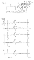
- the pre-tared weighing signals q * are recorded in association with the respectively weighed tape section, so that the course of the weighing signals q * over a tape recirculation n1-n2, as in FIG. 2, curve a represents.
- the weighing signals q * of a belt circulation n1-n2 are stored after deducting the mean value qm * formed from their band sections and summed up over a statistically relevant number of belt revolutions n1-n1 band sections.
- Curves b to d show the typical course of the stored signal curves of successive belt revolutions.
- the described recording and processing of the weighing signal le q * is carried out by the taring device in each case for a fixed, statistically relevant number of belt revolutions which immediately precede the instantly tared belt circulation.
- the signal detection carried out for taring is therefore always limited to a limited section of the weighing process which immediately precedes the current taring, so that slow temporal changes in the influence of the strip are detected and taken into account in taring.
- the procedure described thus enables an optimal, automatic correction of the influence of the belt, even in the case of prolonged, continuous weighing processes.
Abstract
Description
Die Erfindung betrifft ein Verfahren zum Tarieren einer Dosierbandwaage mit kontinuierlicher Dosiergutaufgabe, bei der ein von einer Wägezelle erzeugtes Wägesignal und ein von einer Sensoreinrichtung erzeugtes Bandumlaufsignal einer Tariereinrichtung zugeführt werden, die das Wägesignal bandabschnittsweise erfaßt und um den einem Bandabschnitt jeweils zugeordneten, örtlichen Bandeinfluß korrigiert.The invention relates to a method for taring a dosing belt weigher with continuous dosing, in which a weighing signal generated by a load cell and a belt circulation signal generated by a sensor device are fed to a taring device, which detects the weighing signal in sections and corrects them for the local band influence assigned to each section of the band.
Dosierbandwaagen sind spezielle Bandförderer, mit denen Schüttgüter einem Prozeß mit einer einstellbaren Förderstärke zudosiert werden können. Zur Erfassung der Förderstärke wird die Belastung und die Geschwindigkeit des Bandes gemessen. Das Produkt aus der Nettobandbelastung und der Bandgeschwindigkeit entspricht der Förderstärke, die dosiert und damit geregelt werden soll. Die als Wägesignal gemessene Bandbelastung setzt sich aus dem vom Schüttgut herrührenden Anteil, der Bandbeladung, und dem aus dem Gewicht und den Verformungskräften des Bandes herrührenden Bandeinfluß zusammen. Betrachtet man einen kompletten Bandumlauf, so läßt sich der Bandeinfluß darüber mitteln und das Bandbelastungssignal um diesen Mittelwert korrigieren. Man erhält dann als Nettowert die Bandbeladung, die dem Schüttgut auf dem Band pro Bandumlauf entspricht.Belt weighers are special belt conveyors with which bulk goods can be added to a process with an adjustable conveying force. The load and the speed of the belt are measured to determine the conveying strength. The product of the net belt load and the belt speed corresponds to the delivery rate that is to be metered and thus controlled. The belt load measured as a weighing signal is made up of the proportion of the bulk material, the belt loading, and the belt influence resulting from the weight and the deformation forces of the belt. If you consider a complete band circulation, the band influence can be averaged over it and the band load signal can be corrected by this mean value. The belt load corresponding to the bulk material on the belt per belt circulation is then obtained as a net value.
Für eine Reihe moderner Produktionsverfahren, insbesondere im Bereich der chemischen Industrie, ist eine Dosierkonstanz, d. h. eine Konstanz der Förderstärke an der Abwurfkante des Bandes erforderlich, die durch eine auf ganzzahlige Bandumläufe bezogene Korrektur des Bandein flußes nicht erreicht werden kann, da der Bandeinfluß lediglich im Mittel konstant ist, während eines Bandumlaufs aber erheblichen Schwankungen unterliegt. Um diese Schwankungen des Bandeinflußes bei der Tarakorrektur berücksichtigen zu können, ist es bekannt, die Bandeinflußgrößen bei unbeladenem Band in Zuordnung zu einzelnen Bandabschnitten zu ermitteln und zu speichern. Während des anschließenden Wägeverfahrens werden die abschnittsweise ermittelten Bandeinflußgrößen zuordnungsgenau von den für die entsprechenden Abschnitte ermittelten Wägesignalen subtrahiert, so daß man für jeden Bandabschnitt ein um den örtlichen Bandeinfluß reduziertes Netto-Bandbelastungssignal erhält. Dieses bekannte Verfahren führt jedoch nicht zu der gewünschten Dosiergenauigkeit, da der Verlauf der Bandeinflußfunktion nicht eindeutig ist. Der Bandeinfluß wird vielmehr ganz erheblich von der Betriebsweise der Dosierbandwaage, von der Laufdauer und von der Bandtemperatur bestimmt und ist deshalb langsamen zeitlichen Änderungen unterworden, die durch das bekannte Verfahren nicht erfaßt und ausgeglichen werden können.For a number of modern production processes, particularly in the chemical industry, a constant metering, ie a constant delivery rate at the discharge edge of the belt, is required, which is caused by a correction of the belt related to the number of belt revolutions flow can not be achieved, since the influence of the band is only constant on average, but is subject to considerable fluctuations during a band circulation. In order to be able to take these fluctuations in the band influence into account in the tare correction, it is known to determine and store the band influence quantities in the case of an unloaded band in association with individual band sections. During the subsequent weighing process, the band influence quantities determined in sections are subtracted from the weighing signals determined for the corresponding sections so that a net band load signal reduced by the local band influence is obtained for each band section. However, this known method does not lead to the desired metering accuracy, since the course of the tape influence function is not clear. Rather, the influence of the belt is determined considerably by the operating mode of the weigh feeder, by the running time and by the belt temperature and is therefore subject to slow changes over time, which cannot be detected and compensated for by the known method.
Aufgabe der Erfindung ist es, ein Verfahren zum Tarieren einer Dosierbandwaage der eingangs genannten Art anzugeben, das während des kontinuierlichen Wägevorgangs den sich ändernden Bandeinfluß erfaßt und bei der Korrektur berücksichtigt.The object of the invention is to provide a method for taring a dosing belt scale of the type mentioned at the outset, which detects the changing belt influence during the continuous weighing process and takes it into account in the correction.
Die Aufgabe wird erfindungsgemäß dadurch gelöst, daß durch die Tariereinrichtung aus den Wägesignalen einer statistisch relevanten Zahl von Bandumläufen ein Mittelwert gebildet wird, der mit aus den bandabschnittsweise aufsummierten Wägesignalen dieser Bandumläufe gebildeten, den einzelnen Bandabschnitten zugeordneten Mittelwerten verglichen wird und daß aus den sich daraus ergebenden Differenzwerten Tariersignale zur Korrektur des örtlichen Bandeinflußes des folgenden Bandumlaufs gebildet werden.The object is achieved in that the taring device forms a mean value from the weighing signals of a statistically relevant number of belt revolutions, which is compared with the mean values associated with the individual belt sections and formed from the weighing signals of these belt revolutions accumulated in sections Difference values tare signals for correcting the local band influence of the following band circulation are formed.
Das erfindungsgemäße Verfahren beruht auf der Tatsache, daß sich die Bandbeladung und der Bandeinfluß in ihrem statistischen Verhalten wesentlich voneinander unterscheiden. Der Bandeinfluß ist ortsabhängig und aufgrund der physikalischen Natur seiner Einflußgrößen langsamen zeitlichen Änderungen unterworfen, er bildet also ein quasi-stationäres Signal. Die Schwankungen der Bandbeladung mit Dosiergut haben hingegen rein stochastischen Charakter und sind daher über mehrere Bandumläufe betrachtet in jedem Bandabschnitt in ihrem Mittelwert konstant. Durch das erfindungsgemäße Verfahren lassen sich daher aus dem Wägesignal die örtlichen Bandeinflußgrößen herausfiltern und zur bandabschnittsweisen Tarierung des Bandeinflußes verwenden. Langsame zeitliche Änderungen des Bandeinflußes werden somit erfaßt und bei der Tarierung berücksichtigt. Das erfindungsgemäße Verfahren ermöglicht damit eine hohe bandabschnittsweise Dosiergenauigkeit, die durch Änderungen des Bandeinflusses nicht beeinträchtigt wird.The method according to the invention is based on the fact that the belt loading and the belt influence differ significantly in their statistical behavior. The band influence is location-dependent and, due to the physical nature of its influencing variables, is subject to slow changes over time, so it forms a quasi-stationary signal. The fluctuations of the belt loading with dosing material, on the other hand, have a purely stochastic character and are therefore constant in their mean value when viewed over several belt revolutions in each belt section. By means of the method according to the invention, the local band influencing variables can therefore be filtered out of the weighing signal and used for taring the band influence in sections. Slow changes in the band influence over time are thus recorded and taken into account in taring. The method according to the invention thus enables high metering accuracy in sections, which is not impaired by changes in the influence of the band.
Bei dem erfindungsgemäßen Verfahren kann weiterhin vorgesehen sein, daß zur Bildung der den einzelnen Bandabschnitten zugeordeten Tariersignale von den bandabschnittsweise erfaßten Wägesignalen eines Bandumlaufs jeweils der Mittelwert der aufsummierten Wägesignale des Bandumlaufs subtrahiert wird und daß aus den derart gebildeten Differenzwerten einer statistisch relevanten Zahl von Bandumläufen bandabschnittsweise als Tariersignal dienende Mittelwerte gebildet werden. Eine derartige Verarbeitung der Wägesignale ermöglicht einen einfachen Aufbau der Tariereinrichtung. Erfindungsgemäß kann weiterhin vorgesehen sein, daß die von der Tariereinrichtung verarbeiteten Wägesignale um die bei unbeladenem Band ermittelte durchschnittliche Bandeinflußgröße vermindert sind. Hierbei wird zu Beginn eines kontinuierlichen Wägevorgangs die Dosierbandwaage in unbeladenem Zustand derart tariert, daß der Durchschnitt der Wägesignale bereits der durchschnittlichen Netto-Bandbeladung entspricht.In the method according to the invention, it can further be provided that in order to form the taring signals assigned to the individual belt sections, the mean value of the summed up weighing signals of the belt circulation are subtracted from the weighing signals of a belt circulation recorded by the belt section, and that a statistically relevant number of belt revolutions in sections is recorded from the difference values thus formed Average values serving as a tare signal are formed. Such processing of the weighing signals enables a simple construction of the taring device. According to the invention, it can further be provided that the weighing signals processed by the taring device are reduced by the average band influencing variable determined when the band is unloaded. At the beginning of a continuous weighing process, the dosing belt scale is tared in the unloaded state in such a way that the average of the weighing signals already corresponds to the average net belt load.
Die Erfindung wird nachfolgend an Hand einem Beispiel näher erläutert, das in der Zeichnung dargestellt ist. Es zeigen
Figur 1 eine schematische Darstellung einer Dosierbandwaage mit Tariereinrichtung und- Figur 2 die Wägesignale mehrerer Bandumläufe eines kontinuierlichen Wägevorgangs und das daraus abgeleitete Tariersignal.
- Figure 1 is a schematic representation of a dosing belt scale with tare and
- Figure 2 shows the weighing signals of several belt revolutions of a continuous weighing process and the tare signal derived therefrom.
In Figur 1 ist der prinzipielle Aufbau einer Dosierbandwaage 1 dargestellt. Ein um zwei Trommeln umlaufendes Band 2 entnimmt aus einem Aufgabetrichter 3 ein Dosiergut 4 und führt es in dosierter Förderstärke einem Prozeßbehälter 5 zu. Das Band läuft über eine Wägerolle 6, die von einer Wägezelle 7 getragen wird. Von der Wägezelle 7 wird ein Wägesignal q an eine elektronische Regeleinrichtung 8 übertragen. Zum Antrieb des Bandes 2 ist ein regelbarer Motor 9 vorgesehen, dessen Drehweg von einem Signalgeber 10 zur Bildung eines Bandumlaufsignals n erfaßt und ebenfalls der Regeleinrichtung 8 übermittelt wird. Ein weiterer Signalgeber 11 am Band 2 übermittelt ein Syncronsignal pro Bandumlauf an die Regeleinrichtung 8. In der Regeleinrichtung 8 wird aus dem Wägesignal q und der aus dem Drehweg errechneten Bandgeschwindigkeit die Istförderstärke des Dosierguts kontinuierlich ermittelt und aufgrund eines Vergleichs mit der eingestellten Sollförderstärke durch Steuerung des Motors 9 die Bandgeschwindigkeit so geregelt, daß die dem Prozeßbehälter 5 zugeführte Förderstärke des Dosierguts genau der gewünschten Sollförderstärke entspricht.In Figure 1, the basic structure of a
Um die Istförderstärke aus dem Wägesignal q der Wägezelle 7 ermitteln zu können, ist die Regeleinrichtung 8 mit einer Tariereinrichtung versehen, die die in dem Wägesignal q enthaltene Bandeinflußgröße ermittelt und das Wägesignal q entsprechend korrigiert. Zur Durchführung dieser Korrektur wird zunächst bei unbeladenem Band der Mittelwert des Bandeinflusses pro Bandumlauf ermittelt und gespeichert. Dieser Mittelwert wird bei dem anschließenden kontinuierlichen Wägevorgang durch die Tariereinrichtung von den bandabschnittsweise erfaßten Wägesignalen q subtrahiert, wodurch vortarierte Wägesignale q* gebildet werden, welche sich aus der örtlichen Bandbeladung und den örtlichen Abweichungen der Bandeinflußgröße von dem Mittelwert des Bandeinflusses zusammensetzen. Mit Hilfe des von den Signalgebern 10, 11 gebildeten Bandumlaufsignals n werden die vortarierten Wägesignale q* in Zuordnung zu dem jeweils gewogenen Bandabschnitt aufgezeichnet, so daß sich der Verlauf der Wägesignale q* über einen Bandumlauf n₁-n₂, wie in Figur 2, Kurve a darstellen läßt. Die Wägesignale q* eines Bandumlaufs n₁-n₂ werden nach Abzug des aus ihrer Summe gebildeten Mittelwerts qm* bandabschnittsweise gespeichert und über eine statistisch relevante Zahl von Bandumläufen n₁-n₁ bandabschnittsweise summiert. Die Kurven b bis d geben den typischen Verlauf der gespeicherten Signalkurven aufeinanderfolgender Bandumläufe wieder. Ist die zur Auswertung erforderliche Zahl von Bandumläufen erreicht, so werden aus den für die einzelnen Bandabschnitte aufsummierten Signalen Mittelwerte gebildet, wodurch sich der als Kurve e dargestellte Signalverlauf ergibt. Es zeigt sich, daß der stochastischen Schwankungen unterworfene Bandbeladungsanteil des vortarierten Wägesignals q* durch die Signalverarbeitung zu Null wurde, während der quasi stationäre Bandeinfluß in seiner typischen Ausprägung erhalten geblieben ist. Der Signalverlauf gemäß Kurve e beinhaltet somit nur noch die Schwankungen der Bandeinflußgröße in den einzelnen Bandabschnitten und kann daher als Tariersignal qT zur bandabschnittsweisen Korrektur des Wägesignals q* im folgenden Bandumlauf verwendet werden.In order to be able to determine the actual delivery rate from the weighing signal q of the weighing cell 7, the
Die beschriebene Erfassung und Verarbeitung der Wägesigna le q* wird von der Tariereinrichtung jeweils für eine festgelegte statistisch relevante Zahl von Bandumläufen durchgeführt, die dem augenblicklich tarierten Bandumlauf unmittelbar vorausgehen. Die zur Tarierung durchgeführte Signalerfassung beschränkt sich also immer auf einen begrenzten, der augenblicklichen Tarierung unmittelbar vorausgehenden Abschnitt des Wägevorgangs, so daß langsame zeitliche Veränderungen des Bandeinflusses erfaßt und bei der Tarierung berücksichtigt werden. Die beschriebene Verfahrensweise ermöglicht somit eine optimale, selbsttätige Korrektur des Bandeinflusses auch bei länger andauernden, kontinuierlichen Wägevorgängen.The described recording and processing of the weighing signal le q * is carried out by the taring device in each case for a fixed, statistically relevant number of belt revolutions which immediately precede the instantly tared belt circulation. The signal detection carried out for taring is therefore always limited to a limited section of the weighing process which immediately precedes the current taring, so that slow temporal changes in the influence of the strip are detected and taken into account in taring. The procedure described thus enables an optimal, automatic correction of the influence of the belt, even in the case of prolonged, continuous weighing processes.
Claims (3)
Applications Claiming Priority (2)
| Application Number | Priority Date | Filing Date | Title |
|---|---|---|---|
| DE3933424A DE3933424C1 (en) | 1989-10-06 | 1989-10-06 | |
| DE3933424 | 1989-10-06 |
Publications (2)
| Publication Number | Publication Date |
|---|---|
| EP0421165A1 true EP0421165A1 (en) | 1991-04-10 |
| EP0421165B1 EP0421165B1 (en) | 1993-06-02 |
Family
ID=6390976
Family Applications (1)
| Application Number | Title | Priority Date | Filing Date |
|---|---|---|---|
| EP90117617A Expired - Lifetime EP0421165B1 (en) | 1989-10-06 | 1990-09-13 | Method for taring a conveyor-type dispensing scale |
Country Status (7)
| Country | Link |
|---|---|
| US (1) | US5119893A (en) |
| EP (1) | EP0421165B1 (en) |
| JP (1) | JPH03125927A (en) |
| BR (1) | BR9005009A (en) |
| DE (2) | DE3933424C1 (en) |
| DK (1) | DK0421165T3 (en) |
| ES (1) | ES2041480T3 (en) |
Cited By (3)
| Publication number | Priority date | Publication date | Assignee | Title |
|---|---|---|---|---|
| DE20303126U1 (en) * | 2003-02-25 | 2004-04-01 | Pfister Gmbh | Device for continuous, gravimetric dosing |
| DE10322504A1 (en) * | 2003-05-19 | 2004-12-09 | Garvens Automation Gmbh | Method and device for weighing products |
| CN111056325A (en) * | 2018-10-16 | 2020-04-24 | 中国能源建设集团广东省电力设计研究院有限公司 | Coal flow visualization method and device and computer equipment |
Families Citing this family (26)
| Publication number | Priority date | Publication date | Assignee | Title |
|---|---|---|---|---|
| US5343003A (en) * | 1992-05-29 | 1994-08-30 | Otis Elevator Company | Recalibration of hitch load weighing using dynamic tare |
| US5345042A (en) * | 1992-05-29 | 1994-09-06 | Otis Elevator Company | Elevator hitch load weighing tare compensation |
| US5308930A (en) * | 1992-06-26 | 1994-05-03 | Ishida Scales Mfg. Co., Ltd. | Weighing machine with weight detecting conveyor |
| US5591942A (en) * | 1993-11-08 | 1997-01-07 | Hyer Industries, Inc. | Temperature-compensated belt scale |
| US5547034A (en) * | 1994-01-10 | 1996-08-20 | Accu-Sort Systems, Inc. | Conveyor friction scale |
| US5736682A (en) * | 1995-04-07 | 1998-04-07 | Hauni Machinenbau Ag | Method of and apparatus for ascertaining the mass of rod-shaped articles of the tobacco processing industry |
| KR100323879B1 (en) * | 1997-01-17 | 2002-02-08 | 카이네트 프렝고이스 | Conveyor scale |
| US5949031A (en) * | 1997-09-22 | 1999-09-07 | Vbs, Inc. | Combination scale for conveyor line |
| DE19829036A1 (en) * | 1998-06-30 | 2000-01-05 | Pfister Gmbh | Chain conveyor |
| US6818841B1 (en) * | 2002-02-14 | 2004-11-16 | Mcdonald Ralph R. | Non-disruptive computer-controlled in-line conveyor flow weight calibration scale |
| DE202006004894U1 (en) * | 2006-03-24 | 2007-07-26 | Big Dutchman International Gmbh | Conveyor belt control with force sensor |
| US7534970B2 (en) * | 2006-06-15 | 2009-05-19 | Schenck Accurate, Inc. | Counterbalanced dispensing system |
| US8067704B2 (en) * | 2008-09-08 | 2011-11-29 | Equipfix | System and method for weighing particulate material moving on a conveyor |
| SE532762C2 (en) * | 2009-03-09 | 2010-04-06 | Mats Thulin | Exercise machine and a weight selector system |
| GB2469816B (en) * | 2009-04-28 | 2012-10-31 | Joy Mm Delaware Inc | Conveyor sensor arrangement |
| US8973742B2 (en) | 2010-04-26 | 2015-03-10 | Joy Mm Delaware, Inc. | Chain tension sensor |
| GB2469815B (en) * | 2009-04-28 | 2012-08-29 | Joy Mm Delaware Inc | Armoured face conveyor extendable at head gate end |
| DE102010009753B4 (en) | 2010-03-01 | 2014-09-18 | Schenck Process Gmbh | Device and method for dosing control of bulk material |
| US8636140B2 (en) | 2010-04-26 | 2014-01-28 | Joy Mm Delaware, Inc. | Chain tension sensor |
| US9422112B2 (en) | 2011-07-22 | 2016-08-23 | Joy Mm Delaware, Inc. | Systems and methods for controlling a conveyor in a mining system |
| US9382070B2 (en) | 2012-10-24 | 2016-07-05 | Big Dutchman International Gmbh | Conveyor and method to convey animal products in an agricultural business |
| DE202014007282U1 (en) | 2014-09-12 | 2015-12-16 | Big Dutchman International Gmbh | metering |
| US20170067771A1 (en) * | 2015-09-09 | 2017-03-09 | Usc, Llc | System and method for accurate weight measurement on a weigh belt |
| DE202016105370U1 (en) | 2016-09-27 | 2018-01-02 | Big Dutchman International Gmbh | Feeding device for poultry |
| NL2021276B1 (en) * | 2018-07-10 | 2020-01-20 | Lely Patent Nv | Feed mixing device with calibration function |
| RU2763123C1 (en) * | 2020-07-23 | 2021-12-27 | Федеральное государственное унитарное предприятие «Всероссийский научно-исследовательский институт метрологии им. Д.И.Менделеева» | System providing testing and verification of a weight measurement apparatus, method for testing and verification of a weight measurement apparatus |
Citations (4)
| Publication number | Priority date | Publication date | Assignee | Title |
|---|---|---|---|---|
| FR2241773A1 (en) * | 1973-08-20 | 1975-03-21 | Mac Donald Ralph | |
| US3976150A (en) * | 1973-12-07 | 1976-08-24 | Ramsey Rec Ltd. | Endless conveyor belt load measurement system and method of automatically calibrating same |
| DE2365524B2 (en) * | 1973-05-14 | 1976-10-21 | Ausscheidung aus: 23 24 328 Siemens AG, 1000 Berlin und 8000 München | INDEPENDENT ELECTRIC ZERO SETTING AND SENSITIVITY ADJUSTMENT DEVICE FOR INTEGRATING ELECTROMECHANICAL CONVEYOR SCALES |
| DD232547A1 (en) * | 1984-12-13 | 1986-01-29 | Mech Landwirtsch Forschzent | DOSING |
Family Cites Families (6)
| Publication number | Priority date | Publication date | Assignee | Title |
|---|---|---|---|---|
| US3868643A (en) * | 1973-03-26 | 1975-02-25 | Tron Corp K | Conveyor memory system |
| US4071102A (en) * | 1976-09-27 | 1978-01-31 | K-Tron Corporation | Auto zero circuit |
| US4194649A (en) * | 1977-06-06 | 1980-03-25 | K-Tron International, Inc. | Weigh feeder |
| DE2734562A1 (en) * | 1977-07-30 | 1979-02-08 | Schenck Ag Carl | Monitored operation of conveyor type weigher - weighs goods at input and output of weighing bridge, and trips signal when difference exceeds set value |
| US4418773A (en) * | 1980-12-17 | 1983-12-06 | Stock Equipment Company | Conveyor calibration technique |
| JP2726089B2 (en) * | 1988-03-29 | 1998-03-11 | ケー‐トロン インターナシヨナル インコーポレイテツド | Method and apparatus for controlling supply weight of supplied material |
-
1989
- 1989-10-06 DE DE3933424A patent/DE3933424C1/de not_active Expired - Lifetime
-
1990
- 1990-09-13 EP EP90117617A patent/EP0421165B1/en not_active Expired - Lifetime
- 1990-09-13 ES ES199090117617T patent/ES2041480T3/en not_active Expired - Lifetime
- 1990-09-13 DK DK90117617.2T patent/DK0421165T3/en active
- 1990-09-13 DE DE9090117617T patent/DE59001609D1/en not_active Expired - Lifetime
- 1990-09-28 JP JP2262937A patent/JPH03125927A/en active Pending
- 1990-10-05 US US07/593,104 patent/US5119893A/en not_active Expired - Lifetime
- 1990-10-05 BR BR909005009A patent/BR9005009A/en not_active IP Right Cessation
Patent Citations (4)
| Publication number | Priority date | Publication date | Assignee | Title |
|---|---|---|---|---|
| DE2365524B2 (en) * | 1973-05-14 | 1976-10-21 | Ausscheidung aus: 23 24 328 Siemens AG, 1000 Berlin und 8000 München | INDEPENDENT ELECTRIC ZERO SETTING AND SENSITIVITY ADJUSTMENT DEVICE FOR INTEGRATING ELECTROMECHANICAL CONVEYOR SCALES |
| FR2241773A1 (en) * | 1973-08-20 | 1975-03-21 | Mac Donald Ralph | |
| US3976150A (en) * | 1973-12-07 | 1976-08-24 | Ramsey Rec Ltd. | Endless conveyor belt load measurement system and method of automatically calibrating same |
| DD232547A1 (en) * | 1984-12-13 | 1986-01-29 | Mech Landwirtsch Forschzent | DOSING |
Cited By (5)
| Publication number | Priority date | Publication date | Assignee | Title |
|---|---|---|---|---|
| DE20303126U1 (en) * | 2003-02-25 | 2004-04-01 | Pfister Gmbh | Device for continuous, gravimetric dosing |
| DE10322504A1 (en) * | 2003-05-19 | 2004-12-09 | Garvens Automation Gmbh | Method and device for weighing products |
| US7405368B2 (en) | 2003-05-19 | 2008-07-29 | Mettler-Toledo Garvens Gmbh | Method and device for weighing products |
| CN111056325A (en) * | 2018-10-16 | 2020-04-24 | 中国能源建设集团广东省电力设计研究院有限公司 | Coal flow visualization method and device and computer equipment |
| CN111056325B (en) * | 2018-10-16 | 2022-04-12 | 中国能源建设集团广东省电力设计研究院有限公司 | Coal flow visualization method and device and computer equipment |
Also Published As
| Publication number | Publication date |
|---|---|
| DE3933424C1 (en) | 1991-04-18 |
| US5119893A (en) | 1992-06-09 |
| BR9005009A (en) | 1991-09-10 |
| EP0421165B1 (en) | 1993-06-02 |
| DE59001609D1 (en) | 1993-07-08 |
| DK0421165T3 (en) | 1993-06-28 |
| ES2041480T3 (en) | 1993-11-16 |
| JPH03125927A (en) | 1991-05-29 |
Similar Documents
| Publication | Publication Date | Title |
|---|---|---|
| EP0421165B1 (en) | Method for taring a conveyor-type dispensing scale | |
| DE3641232C2 (en) | ||
| DE2215465C3 (en) | Mass flow control device | |
| DE4323968B4 (en) | Method and device for calibrating a sensor | |
| DE2722618A1 (en) | DEVICE FOR CHIPBOARD PRODUCTION | |
| DE60125623T2 (en) | Combinatorial weighing and counting device | |
| DE2355905A1 (en) | DEVICE FOR BALANCING THE INFLUENCE OF A CONVEYOR BELT WHEN CROSSING A MEASURING POINT | |
| EP2246673A1 (en) | Method for determining the volume of loads and device | |
| DE3037025C2 (en) | ||
| EP0291553B1 (en) | Method to control a differential metering balance, especially for bulk materials, and a differential metering balance for carrying out the method | |
| DE1558551A1 (en) | ||
| EP0140213A1 (en) | Process and device for measuring the mass flow of fluent solid material | |
| EP2181311B1 (en) | Method and apparatus for dynamical check weighing | |
| EP0029236A1 (en) | Apparatus for the thermal spraying of metal and ceramic powders | |
| DE102012017717A1 (en) | Method for calibrating belt weigher for continuous flow rates detection of bulk material in cement plant, involves determining error value of belt weigher, where calibration of weigher is performed during operation of conveying belt | |
| DE102007040300B4 (en) | Method and device for dynamic checkweighing | |
| DE1803372C3 (en) | Method and apparatus for measuring the mass of a number of objects | |
| EP0565740B1 (en) | Method and apparatus for determining the extraction flow rate of a belt weigher | |
| DE102010009753B4 (en) | Device and method for dosing control of bulk material | |
| DE19939669A1 (en) | Device for determining the completeness of a container | |
| EP0706642A1 (en) | Process for determining the conveyor power of a conveyor-belt weigher and a device for carrying this out | |
| DE3206061C1 (en) | Device for the automatic, weight-dependent sorting of objects | |
| DE3543095C2 (en) | ||
| EP1516544B1 (en) | Drying plant for tobacco and method for drying tobacco | |
| DE2340832C3 (en) | Method for achieving a certain final weight of a quantity of KK consisting of several objects. Ishida Koki Seisakusho, Kyoto |
Legal Events
| Date | Code | Title | Description |
|---|---|---|---|
| PUAI | Public reference made under article 153(3) epc to a published international application that has entered the european phase |
Free format text: ORIGINAL CODE: 0009012 |
|
| AK | Designated contracting states |
Kind code of ref document: A1 Designated state(s): BE CH DE DK ES FR GB IT LI LU NL SE |
|
| 17P | Request for examination filed |
Effective date: 19910802 |
|
| 17Q | First examination report despatched |
Effective date: 19920318 |
|
| ITF | It: translation for a ep patent filed |
Owner name: ING. ZINI MARANESI & C. |
|
| GRAA | (expected) grant |
Free format text: ORIGINAL CODE: 0009210 |
|
| AK | Designated contracting states |
Kind code of ref document: B1 Designated state(s): BE CH DE DK ES FR GB IT LI LU NL SE |
|
| REG | Reference to a national code |
Ref country code: DK Ref legal event code: T3 |
|
| REF | Corresponds to: |
Ref document number: 59001609 Country of ref document: DE Date of ref document: 19930708 |
|
| GBT | Gb: translation of ep patent filed (gb section 77(6)(a)/1977) |
Effective date: 19930622 |
|
| ET | Fr: translation filed | ||
| REG | Reference to a national code |
Ref country code: ES Ref legal event code: FG2A Ref document number: 2041480 Country of ref document: ES Kind code of ref document: T3 |
|
| EPTA | Lu: last paid annual fee | ||
| PLBE | No opposition filed within time limit |
Free format text: ORIGINAL CODE: 0009261 |
|
| STAA | Information on the status of an ep patent application or granted ep patent |
Free format text: STATUS: NO OPPOSITION FILED WITHIN TIME LIMIT |
|
| 26N | No opposition filed | ||
| EAL | Se: european patent in force in sweden |
Ref document number: 90117617.2 |
|
| REG | Reference to a national code |
Ref country code: CH Ref legal event code: PUE Owner name: CARL SCHENCK AG TRANSFER- SCHENCK PROCESS GMBH |
|
| NLS | Nl: assignments of ep-patents |
Owner name: SCHENCK PROCESS GMBH |
|
| REG | Reference to a national code |
Ref country code: FR Ref legal event code: TP |
|
| REG | Reference to a national code |
Ref country code: ES Ref legal event code: PC2A |
|
| REG | Reference to a national code |
Ref country code: GB Ref legal event code: IF02 |
|
| PGFP | Annual fee paid to national office [announced via postgrant information from national office to epo] |
Ref country code: ES Payment date: 20090924 Year of fee payment: 20 Ref country code: DK Payment date: 20090910 Year of fee payment: 20 |
|
| PGFP | Annual fee paid to national office [announced via postgrant information from national office to epo] |
Ref country code: NL Payment date: 20090915 Year of fee payment: 20 Ref country code: CH Payment date: 20090923 Year of fee payment: 20 Ref country code: LU Payment date: 20090916 Year of fee payment: 20 Ref country code: GB Payment date: 20090922 Year of fee payment: 20 Ref country code: SE Payment date: 20090915 Year of fee payment: 20 |
|
| PGFP | Annual fee paid to national office [announced via postgrant information from national office to epo] |
Ref country code: DE Payment date: 20090923 Year of fee payment: 20 |
|
| PGFP | Annual fee paid to national office [announced via postgrant information from national office to epo] |
Ref country code: IT Payment date: 20090923 Year of fee payment: 20 |
|
| PGFP | Annual fee paid to national office [announced via postgrant information from national office to epo] |
Ref country code: BE Payment date: 20091023 Year of fee payment: 20 |
|
| REG | Reference to a national code |
Ref country code: NL Ref legal event code: V4 Effective date: 20100913 |
|
| BE20 | Be: patent expired |
Owner name: *SCHENCK PROCESS G.M.B.H. Effective date: 20100913 |
|
| REG | Reference to a national code |
Ref country code: CH Ref legal event code: PL |
|
| REG | Reference to a national code |
Ref country code: DK Ref legal event code: EUP |
|
| REG | Reference to a national code |
Ref country code: GB Ref legal event code: PE20 Expiry date: 20100912 |
|
| EUG | Se: european patent has lapsed | ||
| PG25 | Lapsed in a contracting state [announced via postgrant information from national office to epo] |
Ref country code: GB Free format text: LAPSE BECAUSE OF EXPIRATION OF PROTECTION Effective date: 20100912 |
|
| PG25 | Lapsed in a contracting state [announced via postgrant information from national office to epo] |
Ref country code: NL Free format text: LAPSE BECAUSE OF EXPIRATION OF PROTECTION Effective date: 20100913 |
|
| PGFP | Annual fee paid to national office [announced via postgrant information from national office to epo] |
Ref country code: FR Payment date: 20091001 Year of fee payment: 20 |
|
| REG | Reference to a national code |
Ref country code: ES Ref legal event code: FD2A Effective date: 20120110 |
|
| PG25 | Lapsed in a contracting state [announced via postgrant information from national office to epo] |
Ref country code: ES Free format text: LAPSE BECAUSE OF EXPIRATION OF PROTECTION Effective date: 20100914 |
|
| PG25 | Lapsed in a contracting state [announced via postgrant information from national office to epo] |
Ref country code: DE Free format text: LAPSE BECAUSE OF EXPIRATION OF PROTECTION Effective date: 20100913 |