EP0420440B1 - A method of and system for demodulating position information signals provided by a transducer - Google Patents
A method of and system for demodulating position information signals provided by a transducer Download PDFInfo
- Publication number
- EP0420440B1 EP0420440B1 EP90309910A EP90309910A EP0420440B1 EP 0420440 B1 EP0420440 B1 EP 0420440B1 EP 90309910 A EP90309910 A EP 90309910A EP 90309910 A EP90309910 A EP 90309910A EP 0420440 B1 EP0420440 B1 EP 0420440B1
- Authority
- EP
- European Patent Office
- Prior art keywords
- signals
- servo
- transducer
- track
- converter
- Prior art date
- Legal status (The legal status is an assumption and is not a legal conclusion. Google has not performed a legal analysis and makes no representation as to the accuracy of the status listed.)
- Expired - Lifetime
Links
Images







Classifications
-
- G—PHYSICS
- G11—INFORMATION STORAGE
- G11B—INFORMATION STORAGE BASED ON RELATIVE MOVEMENT BETWEEN RECORD CARRIER AND TRANSDUCER
- G11B5/00—Recording by magnetisation or demagnetisation of a record carrier; Reproducing by magnetic means; Record carriers therefor
- G11B5/48—Disposition or mounting of heads or head supports relative to record carriers ; arrangements of heads, e.g. for scanning the record carrier to increase the relative speed
- G11B5/58—Disposition or mounting of heads or head supports relative to record carriers ; arrangements of heads, e.g. for scanning the record carrier to increase the relative speed with provision for moving the head for the purpose of maintaining alignment of the head relative to the record carrier during transducing operation, e.g. to compensate for surface irregularities of the latter or for track following
- G11B5/596—Disposition or mounting of heads or head supports relative to record carriers ; arrangements of heads, e.g. for scanning the record carrier to increase the relative speed with provision for moving the head for the purpose of maintaining alignment of the head relative to the record carrier during transducing operation, e.g. to compensate for surface irregularities of the latter or for track following for track following on disks
- G11B5/59688—Servo signal format patterns or signal processing thereof, e.g. dual, tri, quad, burst signal patterns
Definitions
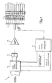
- FIG. 1 is a block diagram of a negative feed back transducer positioning system 8 according to the present invention.
- a stack of magnetically encodable disks is shown generally at 10.
- An electro-mechanical actuator (or E-block) 12 is used to position a servo transducer 14 and a plurality of data transducers 18 radially with respect to a servo disk 16 and data disks 17, respectively.
- the servo transducer is positioned over a desired track on the servo disk 16 where it is held while the data transducers 18, which are also connected to the E-block 12, perform read or write operations.
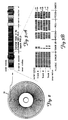
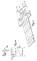
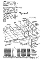
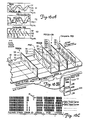
- the magnetic information encoded on adjacent tracks is recorded 180° out of phase. This produces a chequerboard pattern of magnetisation.
- the magnetic information in the PES fields is also recorded plus or minus 90° out of phase with respect to the magnetic information encoded in the PLO/AGC synch field.
- the PES1 field is also called a normal field.
- the boundary between the magnetisation tracks in the normal field are arranged so that they lie on the centre line of the data tracks. Therefore, when the servo transducer 14 is over the normal field, as the servo transducer 14 moves radially further from the centre position 3 of track B, the amplitude of the position signal from the servo transducer 14 is larger. Similarly, as the servo transducer 14 moves radially closer to the centre position 3, the amplitude of the position signal is smaller.
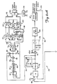
- an automatic gain controlled (AGC'd) analog signal from the AGC loop 34 is transmitted to a voltage comparator 50 which generates serial digital data corresponding to the AGC'd analog signal.
- the comparator 50 provides the serial digital data to a synch detector circuit 52 and a serial-to-parallel shift register 54.
- the switch 118 is opened and the A/D converter 90 is available for conversions 2, 3 and 4 which are conversions for the position samples read from the PES2A, PES1 and PES2B fields. Between position samples, the switch 118 closes to re-set the PES capacitor 84 to the external voltage Vmidref. Hence, the DC null loop 110 compensates for static or time variable DC off-sets in the buffer 88 and the switch 118, which are inside the DC null loop 110. This increases the track following accuracy of the servo transducer 14.
- correction logic 140 (shown in Figures 6B and 13D) is used to detect when it is necessary to correct the track ID so that it corresponds to the track number from which the PES field samples were read.
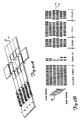
- Figure 13B is a graph of the amplitude of the position signal corresponding to the PES fields, in 2's complement form, as it relates to the least significant bit in the track ID signal.
- Figure 13B also shows a corrected least significant bit in the track ID signal.
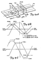
- Figures 15A to 15C show how the addition of the PES2A and PES2B position samples helps to compensate for high radial velocity of the servo transducer 14.
- a slanted trajectory of the servo transducer 14 is shown by arrow 150 in Figure 15A. This slanted trajectory causes an apparent shift in the PES1 and PES2B track crossing plots as shown in Figure 15B.
- the actual value of the PES2A and PES2B fields is shown by a solid line and the ideal value is shown by a dashed line.
- a new track crossing plot, PES2C is formed as shown in Figure 15C.
Landscapes
- Engineering & Computer Science (AREA)
- Signal Processing (AREA)
- Moving Of The Head To Find And Align With The Track (AREA)
- Control Of Position Or Direction (AREA)
- Signal Processing For Digital Recording And Reproducing (AREA)
Description

- b
- core gap width of
transducer 14 - Vm =
- maximum amplitude
- d =
- off track error
- w =
- frequency of position signal.

- n =
- cycles measured
- b =
- width of
transducer 14 - c =
- capacitance of
PES capacitor 84 - Vm =
- maximum AGC'd amplitude
- gm =
- gain through
charge pump 72 - w =
- frequency of position signal.
Claims (9)
- A demodulating system (8) for demodulating position information signals provided by a transducer (14) in response to position information read from a disk in a data storage system (10), the system comprising: amplifier means (34), coupled to the transducer (24), for amplifying the position information signals to provide amplified position signals; rectifier means (70), coupled to the amplifier means (34), for rectifying the amplified position signals to provide rectified position signals; first integrating means (84), selectively coupled to the rectifier means (70), for integrating the rectified position signals to produce position error signals; an analog-to-digital (A/D) converter (90) coupled to the first integrating means (84), for converting the position error signals into logic output signals representative of the position error signals; and nulling means (110), selectively coupled to the first integrating means (84), for providing the first integrating means with a reference signal to initialise the first integrating means (84); characterised in that the A/D converter (90) is time multiplexed between use in controlling the nulling means (110) to initialize the first integrating means (84) and converting the position error signals into the logic output signals.
- A system as claimed in claim 1 characterised in that the nulling means (110) further comprises: null storage means (112), coupled to a bit of the A/D converter (90), for storing the logic level of the bit; second integrating means (114), coupled to the null storage means (116) and selectively coupled to the first integrating means (84), for selectively providing the reference signal to the first integrating means, the reference signal being determined based on the digital value stored in the null storage means (110); and feed back means, coupled to the first integrating means (84) and the A/D converter (90), for feeding the voltage across the first integrating means (84) back to the A/D converter (90) for comparison with a reference signal representing zero position error, the comparison determining the logic level of the bit of the A/D converter stored in the null storage means.
- A system as claimed in claim 1 or 2 characterised by including storing means (94, 96) coupled to the A/D converter (90), for storing logic information representative of the logic output signals; and composite generator means (98, 100, 102, 104, 106, 108), coupled to the storing means, for combining the logic information to form a composite position error signal representative of the position information read from the disk.
- A system as claimed in claim 1, 2 or 3, characterised in that the position information read from the disk is read from a quadrature field (PES2) and a normal field (PES1), the A/D converter (90) converts the position error signals to digital logic signals representative of the position information read from both the quadrature field and the normal field, and the digital logic signals are combined to form a composite position error signal representative of the position information read from both the quadrature field and the normal field, wherein the step of combining is performed after converting the position error signals to the digital logic signals.
- A system as claimed in any of claims 1 to 4 characterised in that the amplifier means (34) comprises: filter means (32), coupled to the transducer (14), for filtering the position information signals to provide filtered signals; and automatic gain control means (34), coupled to the filter means (32), the controller means (24) and the rectifier means (70), for varying amplification of the filtered signals.
- A system as claimed in any of claims 1 to 5 characterised in that the rectifier means further comprises: digital oscillator means (80), selectively coupled to the amplifier means (34), for providing a digital oscillator signal which oscillates 90° out of phase with the amplified position signals; and multiplier means (70), selectively coupled to the amplifier means (34), for multiplying the amplified position signals by the digital oscillator signal to provide the rectified position signals.
- A system as claimed in claim 6 characterised in that the digital oscillator means (80) further comprises: a phase locked oscillator loop (120) for locking onto a signal 90° out of phase with the amplified position signals.
- A method of demodulating position information signals provided by a transducer (14) in response to position information read from a disk in a data storage system (10), the method comprising: amplifying the position information signals to provide amplified position signals; rectifying the amplified position signals to provide rectified position signals; providing integrating means (84) for integrating the rectified position signals to produce position error signals; providing an analog-to-digital (A/D) converter (90) for converting the position error signals into logic output signals representative of the position error signals; and selectively coupling nulling means (110) to the integrating means (84) for providing the integrating means with a reference signal to initialise the integrating means; characterised in that the A/D converter (90) is time multiplexed between use in controlling the nulling means (110) to initialize the integrating means (84) and converting the position error signals into logic output signals.
- A method as claimed in claim 8 characterised in that the position information read from the disk is read from a quadrature field (PES2) and a normal field (PES1), the A/D converter (90) converts the position error signals to digital logic signals representative of the position information from both the quadrature field and the normal field, and the digital logic signals are combined to form a composite position error signal representative of the position information read from both the quadrature field and the normal field, wherein the step of combining is performed after converting the position error signals to the digital logic signals.
Applications Claiming Priority (2)
| Application Number | Priority Date | Filing Date | Title |
|---|---|---|---|
| US07/415,053 US5136439A (en) | 1989-09-29 | 1989-09-29 | Sectored servo position demodulator system |
| US415053 | 1995-03-30 |
Publications (2)
| Publication Number | Publication Date |
|---|---|
| EP0420440A1 EP0420440A1 (en) | 1991-04-03 |
| EP0420440B1 true EP0420440B1 (en) | 1998-11-04 |
Family
ID=23644171
Family Applications (1)
| Application Number | Title | Priority Date | Filing Date |
|---|---|---|---|
| EP90309910A Expired - Lifetime EP0420440B1 (en) | 1989-09-29 | 1990-09-11 | A method of and system for demodulating position information signals provided by a transducer |
Country Status (5)
| Country | Link |
|---|---|
| US (1) | US5136439A (en) |
| EP (1) | EP0420440B1 (en) |
| JP (1) | JP2591527B2 (en) |
| DE (1) | DE69032739T2 (en) |
| SG (1) | SG48781A1 (en) |
Families Citing this family (43)
| Publication number | Priority date | Publication date | Assignee | Title |
|---|---|---|---|---|
| US5210660A (en) * | 1990-01-17 | 1993-05-11 | International Business Machines Corporation | Sectored servo independent of data architecture |
| JPH03225679A (en) * | 1990-01-31 | 1991-10-04 | Sony Corp | Disk drive device |
| JPH06295405A (en) * | 1992-12-18 | 1994-10-21 | Fujitsu Ltd | Writing method for magnetic disk and magnetic disk device |
| US5343340A (en) * | 1992-12-31 | 1994-08-30 | International Business Machines Corporation | Digital servo signal demodulation method and apparatus utilizing a partial-response maximum-likelihood (PRML) channel in a disk file |
| US5424881A (en) | 1993-02-01 | 1995-06-13 | Cirrus Logic, Inc. | Synchronous read channel |
| US5625508A (en) * | 1993-08-26 | 1997-04-29 | International Business Machines Corporation | Method and apparatus for servo demodulation in a direct access storage device |
| JP2735791B2 (en) * | 1993-08-26 | 1998-04-02 | インターナショナル・ビジネス・マシーンズ・コーポレイション | Method and apparatus for rotary actuator arc compensation correction in direct access storage (DASD) |
| US5576906A (en) * | 1994-10-11 | 1996-11-19 | Quantum Corporation | Synchronous detection of concurrent servo bursts for fine head position in disk drive |
| US5847894A (en) * | 1994-12-30 | 1998-12-08 | International Business Machines Corporation | Disk and storage device having an anti-alias data pattern located on a servo sector |
| US5760990A (en) * | 1995-08-08 | 1998-06-02 | Seagate Technology, Inc. | Servo position error signal calibration in a hard disc drive |
| US5774297A (en) * | 1996-03-26 | 1998-06-30 | Seagate Technology, Inc. | Dynamic compensation of servo burst measurement offsets in a disc drive |
| US6046879A (en) * | 1996-05-16 | 2000-04-04 | Seagate Technology, Inc. | Weighted linearization of a position error signal in a disc drive |
| US6108152A (en) * | 1996-10-01 | 2000-08-22 | Seagate Technology, Inc. | Redundant synchronization fields to improve disc drive read performance |
| US5889631A (en) * | 1996-11-19 | 1999-03-30 | Seagate Technology, Inc. | Detecting a track tear servo defect condition in a hard disc drive |
| US5844743A (en) * | 1996-12-20 | 1998-12-01 | Seagate Technology, Inc. | Velocity sensing using actuator coil back-emf voltage |
| US6052804A (en) * | 1997-01-15 | 2000-04-18 | Seagate Technology, Inc. | Data transfer optimization through sector evaluation and reallocation during a disc drive idle mode |
| US6055118A (en) * | 1997-01-15 | 2000-04-25 | Seagate Technology, Inc. | Holding automatic gain control levels during read error recovery in a disc drive |
| US5835300A (en) * | 1997-01-30 | 1998-11-10 | Seagate Technology, Inc. | Dynamic compensation of servo burst measurement offsets in a disc drive |
| US5914836A (en) * | 1997-03-31 | 1999-06-22 | Seagate Technology, Inc. | Cantilevered support for the magnetic circuit of a disc drive voice coil motor |
| US6084738A (en) * | 1997-08-15 | 2000-07-04 | Seagate Technology, Inc. | Writing servo information to a disc drive at a constant density |
| CN1269904A (en) * | 1997-08-15 | 2000-10-11 | 西加特技术有限公司 | Constant density servo information in disc drive |
| US5978169A (en) * | 1997-09-23 | 1999-11-02 | Seagate Technology, Inc. | Repeated servo runout error compensation in a disc drive |
| US6097561A (en) * | 1998-03-09 | 2000-08-01 | Seagate Technology, Inc. | Data recovery in a disc drive with redundant sync data blocks |
| US6690524B1 (en) | 1997-10-16 | 2004-02-10 | Seagate Technology Llc | Data recovery in a disc drive with redundant sync data blocks |
| US6205569B1 (en) | 1997-11-18 | 2001-03-20 | Seagate Technology Llc | Error recovery using alternate headers in a disc drive |
| US6078477A (en) | 1998-07-30 | 2000-06-20 | Seagate Technology, Inc. | Heat transfer plate for an actuator assembly |
| US6392831B1 (en) | 1998-04-16 | 2002-05-21 | Seagate Technology Llc | Identification of defective servo information elements in a disc drive system |
| US6426845B1 (en) | 1998-05-21 | 2002-07-30 | Seagate Technology Llc | Asynchronous analog demodulator and method for a null-type servo pattern |
| US6195220B1 (en) | 1998-05-21 | 2001-02-27 | Seagate Technology Llc | Method and apparatus utilizing field ratioing demodulation techniques for a null-type servo pattern |
| US6243224B1 (en) | 1998-05-21 | 2001-06-05 | Seagate Technology Llc | Asynchronous digital demodulator and method for a null-type servo pattern |
| US6181505B1 (en) | 1998-06-26 | 2001-01-30 | Seagate Technology Llc | Synchronous digital demodulator with integrated read and servo channels |
| US6404582B1 (en) | 1998-09-14 | 2002-06-11 | Seagate Technology Llc | Robust index reference position detection using a sequence of successively disposed index fields |
| US6490117B1 (en) | 1999-03-26 | 2002-12-03 | Seagate Technology Llc | Method of thermally printing servo patterns on magnetic media |
| US6377413B1 (en) | 1999-03-26 | 2002-04-23 | Seagate Technology Llc | Method and apparatus for encoding identification information on a magnetic disc |
| US6574068B1 (en) | 1999-04-21 | 2003-06-03 | Seagate Technology Llc | Servo control using continuous position error signal with high order polynomial component |
| US6490111B1 (en) | 1999-08-25 | 2002-12-03 | Seagate Technology Llc | Method and apparatus for refreshing servo patterns in a disc drive |
| JP4475614B2 (en) * | 2000-04-28 | 2010-06-09 | 大正製薬株式会社 | Job assignment method and parallel processing method in parallel processing method |
| US6600633B2 (en) | 2001-05-10 | 2003-07-29 | Seagate Technology Llc | Thermally conductive overmold for a disc drive actuator assembly |
| US6950270B2 (en) | 2002-04-18 | 2005-09-27 | Seagate Technology Llc | Adaptive index reference position qualification |
| US7511912B2 (en) * | 2002-11-22 | 2009-03-31 | Seagate Technology Llc | Writing multiple servo sector patterns to improve servo sector alignment on multiple surfaces |
| US7957084B2 (en) * | 2008-02-04 | 2011-06-07 | Seagate Technology Llc | Extraction of transducer position information from bit patterned magnetic media |
| US8045282B2 (en) * | 2009-02-03 | 2011-10-25 | Seagate Technology Llc | Measurement of track eccentricity on bit patterned media |
| US8625231B1 (en) * | 2012-11-08 | 2014-01-07 | HGST Netherlands B.V. | Adjusting VGA analog gain for misaligned servo sectors in a disk drive |
Family Cites Families (11)
| Publication number | Priority date | Publication date | Assignee | Title |
|---|---|---|---|---|
| GB2039078B (en) * | 1978-12-27 | 1982-11-24 | Ibm | Sampled data servo positioning system |
| US4414589A (en) * | 1981-12-14 | 1983-11-08 | Northern Telecom Inc. | Embedded servo track following system and method for writing servo tracks |
| DE3378800D1 (en) * | 1982-05-10 | 1989-02-02 | Digital Equipment Corp | Continuous-plus-embedded servo data position control system for magnetic disk device |
| US4590526A (en) * | 1983-11-01 | 1986-05-20 | Amcodyne Incorporated | Method and apparatus for controlling head movement relative to a disk in an embedded servo system |
| JPS60193176A (en) * | 1984-03-13 | 1985-10-01 | Toshiba Corp | Head positioning system |
| US4646175A (en) * | 1984-04-05 | 1987-02-24 | Irwin Magnetic Systems, Inc. | Method and apparatus for positioning transducers by digital conversion of analog-type signals |
| JPS6159677A (en) * | 1984-08-30 | 1986-03-27 | Fujitsu Ltd | Digitizing system of head position signal |
| JPS6232551A (en) * | 1985-08-05 | 1987-02-12 | Fujitsu Ltd | Memory access system |
| US4669004A (en) * | 1986-02-27 | 1987-05-26 | Quantum Corporation | High capacity disk file with embedded sector servo |
| US4679103A (en) * | 1986-04-29 | 1987-07-07 | International Business Machines Corporation | Digital servo control system for a data recording disk file |
| US4823212A (en) * | 1986-11-26 | 1989-04-18 | Hewlett-Packard Company | Sampled servo code format and system for a disc drive |
-
1989
- 1989-09-29 US US07/415,053 patent/US5136439A/en not_active Expired - Lifetime
-
1990
- 1990-09-11 DE DE69032739T patent/DE69032739T2/en not_active Expired - Fee Related
- 1990-09-11 SG SG1996001606A patent/SG48781A1/en unknown
- 1990-09-11 EP EP90309910A patent/EP0420440B1/en not_active Expired - Lifetime
- 1990-09-28 JP JP2260338A patent/JP2591527B2/en not_active Expired - Lifetime
Also Published As
| Publication number | Publication date |
|---|---|
| HK1013172A1 (en) | 1999-08-13 |
| JPH03283147A (en) | 1991-12-13 |
| SG48781A1 (en) | 1998-05-18 |
| DE69032739T2 (en) | 1999-04-01 |
| EP0420440A1 (en) | 1991-04-03 |
| US5136439A (en) | 1992-08-04 |
| DE69032739D1 (en) | 1998-12-10 |
| JP2591527B2 (en) | 1997-03-19 |
Similar Documents
| Publication | Publication Date | Title |
|---|---|---|
| EP0420439B1 (en) | Method of and apparatus for determining the position of a transducer | |
| US5136439A (en) | Sectored servo position demodulator system | |
| US5182682A (en) | Sectored servo disk formatting | |
| US6181505B1 (en) | Synchronous digital demodulator with integrated read and servo channels | |
| US4578723A (en) | Head positioning system with automatic gain control | |
| EP0097209B1 (en) | Magnetizable recording disk and disk file employing servo sector head positioning | |
| EP0471314B1 (en) | Edge servo for disk drive head positioner | |
| US5089757A (en) | Synchronous digital detection of position error signal | |
| EP0786133B1 (en) | Synchronous detection of concurrent servo bursts for fine head position in disk drive | |
| US5774298A (en) | Asynchronous digital PES demodulation disk drive servo control system | |
| US6469849B1 (en) | Field ratioing demodulation circuit for a null-type servo pattern | |
| US4782404A (en) | Positioning system for a disc drive using a stepper motor | |
| US4812929A (en) | Head positioning mechanism for rotating disk data storage system | |
| EP0420438B1 (en) | A method of and apparatus for detecting position error of a transducer | |
| HK1013172B (en) | A method of and system for demodulating position information signals provided by a transducer | |
| HK1002047B (en) | Method of and apparatus for determining the position of a transducer | |
| US4539608A (en) | Low offset position demodular | |
| US5812339A (en) | Method and apparatus for controlling the position of an object along a radial direction of a rotating body | |
| Rose | A high performance embedded servo system | |
| TH23162A (en) | Asymmetrical groove encoding and detection? For servo control systems of disc drives. | |
| JPS61236016A (en) | Magnetic disk device |
Legal Events
| Date | Code | Title | Description |
|---|---|---|---|
| PUAI | Public reference made under article 153(3) epc to a published international application that has entered the european phase |
Free format text: ORIGINAL CODE: 0009012 |
|
| AK | Designated contracting states |
Kind code of ref document: A1 Designated state(s): DE FR GB IT NL |
|
| RIN1 | Information on inventor provided before grant (corrected) |
Inventor name: WEISPFENNING, GERALD LEE Inventor name: GOSS, LLOYD CHAMBERS |
|
| 17P | Request for examination filed |
Effective date: 19910702 |
|
| 17Q | First examination report despatched |
Effective date: 19940104 |
|
| GRAG | Despatch of communication of intention to grant |
Free format text: ORIGINAL CODE: EPIDOS AGRA |
|
| GRAG | Despatch of communication of intention to grant |
Free format text: ORIGINAL CODE: EPIDOS AGRA |
|
| GRAH | Despatch of communication of intention to grant a patent |
Free format text: ORIGINAL CODE: EPIDOS IGRA |
|
| GRAH | Despatch of communication of intention to grant a patent |
Free format text: ORIGINAL CODE: EPIDOS IGRA |
|
| GRAA | (expected) grant |
Free format text: ORIGINAL CODE: 0009210 |
|
| AK | Designated contracting states |
Kind code of ref document: B1 Designated state(s): DE FR GB IT NL |
|
| PG25 | Lapsed in a contracting state [announced via postgrant information from national office to epo] |
Ref country code: IT Free format text: LAPSE BECAUSE OF FAILURE TO SUBMIT A TRANSLATION OF THE DESCRIPTION OR TO PAY THE FEE WITHIN THE PRE;WARNING: LAPSES OF ITALIAN PATENTS WITH EFFECTIVE DATE BEFORE 2007 MAY HAVE OCCURRED AT ANY TIME BEFORE 2007. THE CORRECT EFFECTIVE DATE MAY BE DIFFERENT FROM THE ONE RECORDED.SCRIBED TIME-LIMIT Effective date: 19981104 Ref country code: NL Free format text: LAPSE BECAUSE OF FAILURE TO SUBMIT A TRANSLATION OF THE DESCRIPTION OR TO PAY THE FEE WITHIN THE PRESCRIBED TIME-LIMIT Effective date: 19981104 Ref country code: FR Free format text: LAPSE BECAUSE OF FAILURE TO SUBMIT A TRANSLATION OF THE DESCRIPTION OR TO PAY THE FEE WITHIN THE PRESCRIBED TIME-LIMIT Effective date: 19981104 |
|
| REF | Corresponds to: |
Ref document number: 69032739 Country of ref document: DE Date of ref document: 19981210 |
|
| NLV1 | Nl: lapsed or annulled due to failure to fulfill the requirements of art. 29p and 29m of the patents act | ||
| EN | Fr: translation not filed | ||
| PLBE | No opposition filed within time limit |
Free format text: ORIGINAL CODE: 0009261 |
|
| 26N | No opposition filed | ||
| PGFP | Annual fee paid to national office [announced via postgrant information from national office to epo] |
Ref country code: GB Payment date: 20000804 Year of fee payment: 11 |
|
| PGFP | Annual fee paid to national office [announced via postgrant information from national office to epo] |
Ref country code: DE Payment date: 20000825 Year of fee payment: 11 |
|
| PG25 | Lapsed in a contracting state [announced via postgrant information from national office to epo] |
Ref country code: GB Free format text: LAPSE BECAUSE OF NON-PAYMENT OF DUE FEES Effective date: 20010911 |
|
| GBPC | Gb: european patent ceased through non-payment of renewal fee |
Effective date: 20010911 |
|
| PG25 | Lapsed in a contracting state [announced via postgrant information from national office to epo] |
Ref country code: DE Free format text: LAPSE BECAUSE OF NON-PAYMENT OF DUE FEES Effective date: 20020501 |