EP0420306B1 - Pressure equalization systems - Google Patents
Pressure equalization systems Download PDFInfo
- Publication number
- EP0420306B1 EP0420306B1 EP90201159A EP90201159A EP0420306B1 EP 0420306 B1 EP0420306 B1 EP 0420306B1 EP 90201159 A EP90201159 A EP 90201159A EP 90201159 A EP90201159 A EP 90201159A EP 0420306 B1 EP0420306 B1 EP 0420306B1
- Authority
- EP
- European Patent Office
- Prior art keywords
- aircraft
- compartment
- closure
- pressure
- latch
- Prior art date
- Legal status (The legal status is an assumption and is not a legal conclusion. Google has not performed a legal analysis and makes no representation as to the accuracy of the status listed.)
- Expired - Lifetime
Links
- 230000000295 complement effect Effects 0.000 claims description 2
- 230000000694 effects Effects 0.000 claims description 2
- 230000006837 decompression Effects 0.000 description 13
- 230000000712 assembly Effects 0.000 description 7
- 238000000429 assembly Methods 0.000 description 7
- 239000002184 metal Substances 0.000 description 3
- 230000000717 retained effect Effects 0.000 description 2
- 230000033228 biological regulation Effects 0.000 description 1
- 230000003750 conditioning effect Effects 0.000 description 1
- 230000001419 dependent effect Effects 0.000 description 1
- 238000010438 heat treatment Methods 0.000 description 1
- 239000000463 material Substances 0.000 description 1
Images


Classifications
-
- B—PERFORMING OPERATIONS; TRANSPORTING
- B64—AIRCRAFT; AVIATION; COSMONAUTICS
- B64C—AEROPLANES; HELICOPTERS
- B64C1/00—Fuselages; Constructional features common to fuselages, wings, stabilising surfaces or the like
- B64C1/18—Floors
-
- B—PERFORMING OPERATIONS; TRANSPORTING
- B64—AIRCRAFT; AVIATION; COSMONAUTICS
- B64C—AEROPLANES; HELICOPTERS
- B64C1/00—Fuselages; Constructional features common to fuselages, wings, stabilising surfaces or the like
- B64C2001/009—Fuselages; Constructional features common to fuselages, wings, stabilising surfaces or the like comprising decompression panels or valves for pressure equalisation in fuselages or floors
Definitions
- the present invention relates to novel, improved systems which keep the sudden decompression of a compartment in an aircraft body from collapsing a floor or other wall between that compartment and a pressurized compartment on the other side of the wall and from damaging components such as electrical leads, control cables, and hydraulic lines routed through the aircraft body adjacent the dividing wall, and to aircraft comprising such systems.
- the invention relates to an aircraft having a first pressurizable compartment, a second pressurizable compartment, wall means between said first and second compartments and dump means to which air can flow from the first of said compartments and pressure equalization means automatically operable coincident with a sudden decrease of the pressure in the second compartment to increase the area of the flow path between said first compartment and said dump means and thereby allow the pressure between the first and second compartments to equalize with sufficient rapidity to prevent the differential in pressure between the first and second compartments from collapsing or otherwise damaging said wall means or components of the aircraft in the proximity of said wall means, there being a passage between said dump means and said first compartment, and the pressure equalization means comprising: a closure means spanning said passage, means mounting said closure means for pivotable movement about a first axis located at a first edge thereof relative to a structural part of said aircraft a latch means having one component fixed relative to said aircraft structural part and a pivotable second component which is connected to said closure means and is so engageable with said first component that said sudden decrease
- Modern, commercial jet aircraft are designed to fly at altitudes where the air is too thin to support human life, let alone dense enough to allow passengers to travel in comfort. Also, at these high altitudes, cargo exposed to the ambient pressure might well be damaged or destroyed. Consequently, the cargo, baggage, and passenger compartments of aircraft of this character are almost always pressurized.
- One approach to guaranteeing safe decompression employs a panel or other closure which will automatically open if decompression occurs, providing a communicating passage of large cross-sectional area between the depressurized compartment and any compartment(s) which remain pressurized. This allows air to flow from the pressurized compartment(s) into the depressurized compartment fast enough that differential pressures on wall or floor structures between the thus communicated compartments will not build up to a level at which the dividing wall or critical aircraft components routed adjacent that structure might occur.
- Typical, heretofore proposed pressure equalization systems of the type under discussion have employed folding or hinged vent panels or other configurations which allow foreign material to collect and interfere with the proper functioning of the system. Often, such systems are also complicated and therefore expensive, bulky, heavy, and difficult to install and remove for servicing.
- a pressure equalization system having a first or inner panel and a second or outer panel, both panels being hinged to the aircraft wall structure by means of parallel hinges.
- the outer panel is a two part structure, having an intermediate hinge running parallel to the other hinges.
- the outer panel further comprises a latch that engages the lower edge of the opening that is covered by the inner panel. The tip of the latch further engages the inner panel, and serves to push this panel shut.
- the panels are also coupled by a tension spring.
- a novel pressure equalization system which is like those heretofore proposed in that it includes a closure which is automatically opened when decompression occurs to equalize the pressure between the decompressed aircraft compartment and a pressurized compartment with sufficient rapidity to prevent structural damage to a wall, floor, or deck between the two compartments or to critical aircraft components routed adjacent the dividing wall.
- our novel systems differ from those of this type heretofore proposed in that they are simple, compact, relatively inexpensive, light, easy to install and remove for servicing, and otherwise superior to the heretofore proposed ones.
- said second latch component is mounted on said closure means for a pivotable movement about a second axis located at a second edge thereof opposite said first edge.
- Decompression of the second compartment the aircraft's baggage compartment creates a pressure differential across the latch actuator, pivoting it away from the associated closure of the pressure equalization system and disengaging the latch from its keeper.
- This allows the pressure differential-generated force across the actuator and the pivotable closure to thereafter swing the closure away from that end of the pressure equalization passage which it normally covers.
- This greatly increases the rate at which air can flow from the still pressurized passenger compartment toward the decompressed aircraft compartment.
- the pressure between those two compartments is rapidly equalized, preventing damage to a floor or other wall structure therebetween or to critical aircraft components routed along that wall.
- a first spring system restores the closure to its normal operating or closed position and a second spring system pivots the latch actuator toward the closure member, reengaging the actuator-carried latch with its stationary keeper to hold the closure member in place.
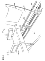
- FIG. 1 depicts a passenger cabin 20 in an aircraft body or fuselage 22 (see FIGS. 2-4).
- Cabin 20 has the usual interior walls 24 (only one of which is showing) with windows 28 and a floor 30 on which passenger seats 32 are supported.
- a cargo hold or baggage compartment identified generally by reference character 34.
- a series of pressure relief or equalization systems 36 constructed in accord with, and embodying, the principles of the present invention. It is the function of these novel systems 36 to accommodate a rapid flow of air from pressurized passenger compartment 20 into a relatively large volume dump 38 between interior cabin wall 24 and the outer skin 40 of the aircraft (see FIG. 3) if there is a sudden loss of pressure in (i.e., decompression of) cargo hold or baggage compartment 34. As discussed above, this results in a rapid equalization of pressure between passenger compartment 20 and cargo hold 34. That prevents the build-up of pressure differential-generated forces which might collapse or otherwise damage passenger compartment floor 30 or produce catastrophic results by damaging such vital components as control cables, electrical leads, and hydraulic lines routed beneath and adjacent floor 30.
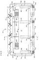
- each of the novel systems 36 discussed briefly above includes an elongated closure or panel 42.
- This component of system 36 is pivotably supported from cabin wall 24 by a hinge 46 which extends generally from end-to-end of the closure member as shown in FIG. 2.
- This hinge-type mounting arrangement allows panel 42 to be displaced from a closure position (see FIG. 3) in which the panel covers a passage 48 between passenger compartment 20 and dump 38 and an open position (see FIG. 5) in which air can flow in large volume through passage 48 into dump 38 from passenger compartment 20.
- dump 38 also serves as a return duct for heating and conditioning air supplied to cabin 20.
- panel 42 is in the closed position shown in FIG. 3; and air flows into dump 38 from cabin 20 through a central opening 49 in panel 42, a duct 50 mounted on the panel, and a grill 52 at the discharge end of duct 50.
- Duct 50 is a tubular component with a generally rectangular cross section. It is fitted into the opening 49 through closure 42. A flange 54 at the outer end of the duct is seated in a recess 56 surrounding the opening 49 in panel 42.
- Grill 52 has a set of apertures 58 therethrough and a configuration matching that of duct 50. It is installed on the inner end 60 of the duct as indicated above and shown in FIGS. 3-5.
- closure 42 is held in the closed position shown in FIG. 3 against the bias exerted by coil springs 62 and retained in that position by a set of four, essentially identical latch assemblies, each identified generally by reference character 64.
- each of the hinges 62 exerts on closure member 42 a force which acts in the direction indicated by arrow 76 in FIG. 3-5 to urge panel 42 toward its open position.
- the four latch assemblies 64 are spaced equidistantly along closure 42 with two of the latch assemblies at opposite ends 78 and 80 of the closure. Near, and at opposite ends of, latch assemblies 64 are latches 82; and there are a keeper 84 and actuator 86 which extend generally from end-to-end of closure 42 and are common to all four latch assemblies 64.
- Keeper 84 is a sheet metal component having integral, normally oriented legs 88 and 90 and a vertically extending, latch lip 92 at the inner end of leg 90.
- the keeper is supported from the vertical segment 94 of a structural floor component 96 by the keeper support assembly 98 shown in FIGS. 3-5.
- That assembly includes an elongated bracket 100; an elongated spring clip 102 and seal 104 which embrace the opposite sides of structural support segment 94 and support bracket 100 therefrom; and support assemblies identified generally by reference character 106. These support the keeper from bracket 100.
- closure 42 Fixed to the support-associated leg 88 of keeper 84 is an elongated, sheet metal stop 108 with an inwardly directed lip 110.
- lip 110 is seated in a complementary recess 112 at the lower edge 114 of closure 42. This keeps closure 42 from traveling in the counterclockwise direction beyond the desired, illustrated, closed position shown in FIG. 3.
- Stop 108, bracket 100, seal 104, structural floor component 94, and a seal 115 to which the leaf 70 of panel-supporting hinge 46 is attached also cooperate to keep air from leaking past panel 42 into flow passage 48.
- each latch actuator 86 of each latch assembly 64 is an elongated, sheet metal stop which extends generally from end-to-end of closure 42 as is best shown in FIG. 2.
- a channel 116 is preferably fixed to the rear side 117 of the actuator adjacent its lower edge 118.
- channels 120 with tapered side walls 122 are fixed to the front side 124 of actuator 86. As shown in FIG. 2, these channels are located at the opposite ends 125 and 126 of actuator 26 and at two equidistant, intermediate locations.
- Latch actuator 86 is pivotably supported from closure 42 for rotation about an axis parallel to the axis of rotation of hinge pin 66 and at the lower edge 114 of the closure by an elongated pivot pin 127.
- This pin extends through the flanges 122 of the four actuator associated channels 120 and generally C-shaped supports 128 fixed to the rear side 129 of panel 42. Hinge pin 127 is retained in place as by keepers 130 (see FIG. 2).
- Actuator 86 is biased or urged toward closure 42 in the clockwise direction indicated by arrow 132 in FIG. 3 by four coil springs 134. These springs are supported on and surround pivot pin 127 at locations corresponding to those of the actuator-supporting and -bracing channels 120 in which they are disposed.
- latch actuator 86 biased toward closure 42 as indicated by arrow 132, the two latches 82 of the four latch assemblies 64 are urged over the two latch lips 92 of keepers 84 until lips 92 are seated in the notches 136 in the free ends 138 of latches 82, thereby latching closure 42 in the closed position shown in FIG. 3.
- a series of pressure equalization systems 36 of the character just described are preferably installed on each side of passenger compartment 20. This generates sufficient flow passage capacity to accomplish pressure equalization with the speed needed to prevent damage to floor 30 and/or any critical components routed beneath that floor or through the aircraft body.
Landscapes
- Engineering & Computer Science (AREA)
- Mechanical Engineering (AREA)
- Aviation & Aerospace Engineering (AREA)
- Air-Flow Control Members (AREA)
- Body Structure For Vehicles (AREA)
Description
- The present invention relates to novel, improved systems which keep the sudden decompression of a compartment in an aircraft body from collapsing a floor or other wall between that compartment and a pressurized compartment on the other side of the wall and from damaging components such as electrical leads, control cables, and hydraulic lines routed through the aircraft body adjacent the dividing wall, and to aircraft comprising such systems. More specifically, the invention relates to an aircraft having a first pressurizable compartment, a second pressurizable compartment, wall means between said first and second compartments and dump means to which air can flow from the first of said compartments and pressure equalization means automatically operable coincident with a sudden decrease of the pressure in the second compartment to increase the area of the flow path between said first compartment and said dump means and thereby allow the pressure between the first and second compartments to equalize with sufficient rapidity to prevent the differential in pressure between the first and second compartments from collapsing or otherwise damaging said wall means or components of the aircraft in the proximity of said wall means, there being a passage between said dump means and said first compartment, and the pressure equalization means comprising: a closure means spanning said passage, means mounting said closure means for pivotable movement about a first axis located at a first edge thereof relative to a structural part of said aircraft a latch means having one component fixed relative to said aircraft structural part and a pivotable second component which is connected to said closure means and is so engageable with said first component that said sudden decrease in pressure will create a pressure differential between the first compartment and dump means and across said second component of sufficient magnitude to pivot said second latch component out of engagement with the first latch component and to effect a rotation of said closure means about said mounting means to an open position in which essentially the full area of said passage is available for the pressure equalizing flow of air from said first compartment to said dump means. Such an aircraft is known from DE-A-3011109.
- Modern, commercial jet aircraft are designed to fly at altitudes where the air is too thin to support human life, let alone dense enough to allow passengers to travel in comfort. Also, at these high altitudes, cargo exposed to the ambient pressure might well be damaged or destroyed. Consequently, the cargo, baggage, and passenger compartments of aircraft of this character are almost always pressurized.
- Decompression of a pressurized compartment in a jet aircraft is not unknown. In one highly publicized incident in recent years, a cargo hatch was lost in flight, causing almost instantaneous decompression from a below deck baggage compartment. This resulted in a pressure differential across the floor of a passenger compartment above the cargo hold which, while perhaps not large, was applied to a relatively large area. This resulted in the floor of the passenger compartment being forced downwardly, damaging control cables routed beneath that floor. As a result, the pilots lost control of the aircraft which ultimately crashed with a disastrous loss of life.
- Partially because of this highly publicized accident, governmental agencies in a number of countries have enacted regulations requiring that aircraft with pressurized compartments be constructed so that even extremely rapid decompression of one or more compartments can be safely accommodated.
- One approach to guaranteeing safe decompression employs a panel or other closure which will automatically open if decompression occurs, providing a communicating passage of large cross-sectional area between the depressurized compartment and any compartment(s) which remain pressurized. This allows air to flow from the pressurized compartment(s) into the depressurized compartment fast enough that differential pressures on wall or floor structures between the thus communicated compartments will not build up to a level at which the dividing wall or critical aircraft components routed adjacent that structure might occur.
- Pressure equalization systems of the character just described are disclosed in: U.S. patents Nos. 3,938,764 issued 17 February 1976 to McIntyre et al. for FRANGIBLE AIRCRAFT FLOOR; 4,033,247 issued 5 July 1977 to Murphy for VENT STRUCTURE; 4,390,152 issued 28 June 1983 to Jorgensen for AIRCRAFT DECOMPRESSION VENT ASSEMBLY; 4,432,514 issued 21 February 1984 to Brandon for DECOMPRESSION EQUALIZATION RELIEF VALVE; and in French patent No. 2,906,877 dated 5 November 1976, and entitled DISPOSITIF DE SECURITE CONTRE DECOMPRESSION BRUT ALE DE SOUTES-D'AERONEFS.
- Typical, heretofore proposed pressure equalization systems of the type under discussion have employed folding or hinged vent panels or other configurations which allow foreign material to collect and interfere with the proper functioning of the system. Often, such systems are also complicated and therefore expensive, bulky, heavy, and difficult to install and remove for servicing.
- In DE-A-30111109 there is disclosed a pressure equalization system having a first or inner panel and a second or outer panel, both panels being hinged to the aircraft wall structure by means of parallel hinges. The outer panel is a two part structure, having an intermediate hinge running parallel to the other hinges. The outer panel further comprises a latch that engages the lower edge of the opening that is covered by the inner panel. The tip of the latch further engages the inner panel, and serves to push this panel shut. The panels are also coupled by a tension spring.
- We have now invented, and disclosed herein, a novel pressure equalization system which is like those heretofore proposed in that it includes a closure which is automatically opened when decompression occurs to equalize the pressure between the decompressed aircraft compartment and a pressurized compartment with sufficient rapidity to prevent structural damage to a wall, floor, or deck between the two compartments or to critical aircraft components routed adjacent the dividing wall. However, our novel systems differ from those of this type heretofore proposed in that they are simple, compact, relatively inexpensive, light, easy to install and remove for servicing, and otherwise superior to the heretofore proposed ones. This is accomplished according to the invention, in that said second latch component is mounted on said closure means for a pivotable movement about a second axis located at a second edge thereof opposite said first edge.
- Preferred embodiments of the pressure equalization system of the invention form the subject matter of the dependent claims.
- Decompression of the second compartment the aircraft's baggage compartment, for example, creates a pressure differential across the latch actuator, pivoting it away from the associated closure of the pressure equalization system and disengaging the latch from its keeper. This allows the pressure differential-generated force across the actuator and the pivotable closure to thereafter swing the closure away from that end of the pressure equalization passage which it normally covers. This greatly increases the rate at which air can flow from the still pressurized passenger compartment toward the decompressed aircraft compartment. As a consequence, the pressure between those two compartments is rapidly equalized, preventing damage to a floor or other wall structure therebetween or to critical aircraft components routed along that wall.
- Once the pressure is equalized, a first spring system restores the closure to its normal operating or closed position and a second spring system pivots the latch actuator toward the closure member, reengaging the actuator-carried latch with its stationary keeper to hold the closure member in place.
- From the foregoing, it will be apparent to the reader that important advantages of the invention reside in the provision of pressure equalization systems
which are relatively simple;
which are comparatively light;
which are relatively compact and thereby conserve space;
which, can be installed without protruding into the interior of an aircraft passenger compartment;
which are relatively inexpensive;
which are easy to install and remove; and
which have a pivotably mounted closure member with a grill through which air can flow during normal operation and an actuator which is operated by a pressure-generated force when decompression of a compartment occurs to disengage a latch and allow the pressure differential to swing the closure away from and uncover a relatively large flow passage, thereby allowing air to escape from the still pressurized component with specific rapidity to prevent damage to structural or other critical components. - Other important objects and features and additional advantages of the invention will be apparent to the reader from the foregoing and the appended claims and as the ensuing detailed description and discussion of the invention proceeds in conjunction with the accompanying drawing.
- In the drawing:
- FIG. 1 is a pictorial view of the interior of an aircraft which is equipped with a pressure equalization system embodying the principles of the present invention to keep depressurization of a cargo compartment from collapsing or otherwise damaging the floor of the pressure compartment or damaging control cables, electrical leads, hydraulic lines, or other components routed through the aircraft body or beneath the floor;
- FIG. 2 is a front view of a vent panel and associated components employed in the pressure equalization system of FIG. 1.
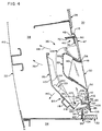
- FIG. 3 is a section through the vent panel of FIG. 2, taken substantially along line 3-3 of FIG. 2 and showing the vent panel in a closed position;
- FIG. 4 is view similar to FIG. 3 but showing a latch mechanism employed to keep the vent panel in the closed position disengaged by application of a decompression-generated pressure differential to the vent panel; and
- FIG. 5 is a view similar to FIGS. 3 and 4 but with the vent panel biased open to create a path through which air can flow out of a second, pressurized chamber with sufficient rapidity to avoid the collapse of or damage to a wall between the pressurized and decompressed compartments or damage to components routed adjacent that wall.
- Referring now to the drawing, FIG. 1 depicts a
passenger cabin 20 in an aircraft body or fuselage 22 (see FIGS. 2-4). Cabin 20 has the usual interior walls 24 (only one of which is showing) withwindows 28 and afloor 30 on whichpassenger seats 32 are supported. On the other side of, and beneath,floor 30, is a cargo hold or baggage compartment identified generally byreference character 34. - Also incorporated in, and a salient feature of, the aircraft just briefly described is a series of pressure relief or
equalization systems 36 constructed in accord with, and embodying, the principles of the present invention. It is the function of thesenovel systems 36 to accommodate a rapid flow of air frompressurized passenger compartment 20 into a relativelylarge volume dump 38 betweeninterior cabin wall 24 and theouter skin 40 of the aircraft (see FIG. 3) if there is a sudden loss of pressure in (i.e., decompression of) cargo hold orbaggage compartment 34. As discussed above, this results in a rapid equalization of pressure betweenpassenger compartment 20 and cargo hold 34. That prevents the build-up of pressure differential-generated forces which might collapse or otherwise damagepassenger compartment floor 30 or produce catastrophic results by damaging such vital components as control cables, electrical leads, and hydraulic lines routed beneath andadjacent floor 30. - Referring now most specifically FIGS. 2-5, each of the
novel systems 36 discussed briefly above includes an elongated closure orpanel 42. This component ofsystem 36 is pivotably supported fromcabin wall 24 by ahinge 46 which extends generally from end-to-end of the closure member as shown in FIG. 2. This hinge-type mounting arrangement allowspanel 42 to be displaced from a closure position (see FIG. 3) in which the panel covers apassage 48 betweenpassenger compartment 20 anddump 38 and an open position (see FIG. 5) in which air can flow in large volume throughpassage 48 intodump 38 frompassenger compartment 20. This rapidly reduces the pressure in the pressurized passenger compartment to a level near or approaching that in the decompressed cargo hold 34, thus keeping forces of sufficient magnitude to cause structural or other damage from being exerted onpassenger compartment floor 30 or components routed beneath that floor or through the aircraft body. - In normal operation of the aircraft partially shown in pictorial form in FIG. 1,
dump 38 also serves as a return duct for heating and conditioning air supplied tocabin 20. In this mode of operation,panel 42 is in the closed position shown in FIG. 3; and air flows intodump 38 fromcabin 20 through acentral opening 49 inpanel 42, aduct 50 mounted on the panel, and agrill 52 at the discharge end ofduct 50. - Duct 50 is a tubular component with a generally rectangular cross section. It is fitted into the
opening 49 throughclosure 42. Aflange 54 at the outer end of the duct is seated in arecess 56 surrounding the opening 49 inpanel 42. -
Grill 52 has a set ofapertures 58 therethrough and a configuration matching that ofduct 50. It is installed on theinner end 60 of the duct as indicated above and shown in FIGS. 3-5. - Thus, in the normal operation of the aircraft, return air flows from
cabin 20 throughopening 49,duct 50, and theapertures 58 ingrill 52 into dump/returnduct 38. - In this mode of operation,
closure 42 is held in the closed position shown in FIG. 3 against the bias exerted bycoil springs 62 and retained in that position by a set of four, essentially identical latch assemblies, each identified generally byreference character 64. - As is best shown in FIG. 2, the biasing springs 62 just discussed are supported on the
pin 66 of closure-supportinghinge 46 at locations spaced therealong with oneend 68 of each spring fixed to the structural member-associatedleaf 70 of the hinge and theother end 72 of the spring fixed to the cooperatingleaf 74 from whichclosure 42 is supported. As a result, each of thehinges 62 exerts on closure member 42 a force which acts in the direction indicated byarrow 76 in FIG. 3-5 to urgepanel 42 toward its open position. - Referring still to FIGS. 3-5, the four
latch assemblies 64 are spaced equidistantly alongclosure 42 with two of the latch assemblies at opposite ends 78 and 80 of the closure. Near, and at opposite ends of,latch assemblies 64 arelatches 82; and there are akeeper 84 andactuator 86 which extend generally from end-to-end ofclosure 42 and are common to all fourlatch assemblies 64. -
Keeper 84 is a sheet metal component having integral, normally orientedlegs latch lip 92 at the inner end ofleg 90. The keeper is supported from thevertical segment 94 of astructural floor component 96 by thekeeper support assembly 98 shown in FIGS. 3-5. That assembly includes anelongated bracket 100; anelongated spring clip 102 and seal 104 which embrace the opposite sides ofstructural support segment 94 andsupport bracket 100 therefrom; and support assemblies identified generally byreference character 106. These support the keeper frombracket 100. - Fixed to the support-associated
leg 88 ofkeeper 84 is an elongated,sheet metal stop 108 with an inwardly directedlip 110. Asclosure 42 is pivotably displaced to, and reaches, the closed position shown in FIG. 3,lip 110 is seated in acomplementary recess 112 at thelower edge 114 ofclosure 42. This keepsclosure 42 from traveling in the counterclockwise direction beyond the desired, illustrated, closed position shown in FIG. 3. - Stop 108,
bracket 100,seal 104,structural floor component 94, and aseal 115 to which theleaf 70 of panel-supportinghinge 46 is attached also cooperate to keep air from leakingpast panel 42 intoflow passage 48. - Referring still to FIGS. 2-5, the
latch actuator 86 of eachlatch assembly 64 is an elongated, sheet metal stop which extends generally from end-to-end ofclosure 42 as is best shown in FIG. 2. To make it more rigid, achannel 116 is preferably fixed to therear side 117 of the actuator adjacent itslower edge 118. - Four
channels 120 with taperedside walls 122 are fixed to thefront side 124 ofactuator 86. As shown in FIG. 2, these channels are located at the opposite ends 125 and 126 of actuator 26 and at two equidistant, intermediate locations. -
Latch actuator 86 is pivotably supported fromclosure 42 for rotation about an axis parallel to the axis of rotation ofhinge pin 66 and at thelower edge 114 of the closure by anelongated pivot pin 127. This pin extends through theflanges 122 of the four actuator associatedchannels 120 and generally C-shapedsupports 128 fixed to the rear side 129 ofpanel 42.Hinge pin 127 is retained in place as by keepers 130 (see FIG. 2). -
Actuator 86 is biased or urged towardclosure 42 in the clockwise direction indicated byarrow 132 in FIG. 3 by four coil springs 134. These springs are supported on andsurround pivot pin 127 at locations corresponding to those of the actuator-supporting and -bracingchannels 120 in which they are disposed. - With
latch actuator 86 biased towardclosure 42 as indicated byarrow 132, the twolatches 82 of the fourlatch assemblies 64 are urged over the twolatch lips 92 ofkeepers 84 untillips 92 are seated in thenotches 136 in the free ends 138 oflatches 82, thereby latchingclosure 42 in the closed position shown in FIG. 3. - In the event of a sudden reduction of pressure in
cargo compartment 34, the pressure indump 38 will almost immediately drop to the same pressure. However, because the flow of air from the stillpressurized passenger compartment 20 intodump 38 is limited by the relatively small flow area provided by theapertures 58 ingrill 52, the pressure in the passenger compartment will decrease only slowly as long as those apertures furnish the only egress for air from the passenger compartment. As a result, the pressures on opposite sides of the flap-like latch actuator 86 will be unequal, generating a force which will rotate the actuator in the counterclockwise direction indicated byarrow 140 in FIG. 4 against the bias exerted by coil springs 134. This continues until the hooklike, free ends 138 of thelatches 82 clear thelip 92 ofkeeper 84. - This disengagement of
latches 82 fromkeeper 84 freesclosure 42 for rotation abouthinge pin 66 in the clockwise direction indicated byarrow 141. Thereafter, the force attributable to the pressure differential acrosslatch actuator 86,closure 42, and thegrill 52 at theinner end 60 ofduct 50 will rotateclosure 42 in that direction from the closed position of FIG. 4 to the open position shown in FIG. 5, exposingpassage 48. Then, air can flow at a high rate frompassenger cabin 20 through the large area ofpassage 48 intodump 38 andcargo compartment 34. This allows the pressure between the two compartments to equalize in a sufficiently short period of time to prevent the imposition of unacceptable stresses on thefloor 30 of the passenger compartment. - As the pressures in the two
compartments equalization system 36 equalizes, the force available to maintainclosure 42 in an open position shown in FIG. 5 by the coil springs 62surrounding hinge pin 66 will continue. Manually moving theclosure 42 against the bias exerted bycoil springs 62 in the counterclockwise direction indicated by arrow 142 in FIG. 5 to the closed and latched position depicted in FIG. 3 will restore theclosure 42 to its original setting. - As suggested by FIG. 1, a series of
pressure equalization systems 36 of the character just described are preferably installed on each side ofpassenger compartment 20. This generates sufficient flow passage capacity to accomplish pressure equalization with the speed needed to prevent damage tofloor 30 and/or any critical components routed beneath that floor or through the aircraft body. - While the principles of our invention have above been developed with respect to an aircraft having an above-deck passenger compartment and a below-deck cargo compartment, the applications of the invention are by no means restricted to aircraft of this particular type. For example, it will be obvious to those skilled in the technical field to which this invention relates that our invention may well be employed in all-cargo aircraft, for example.
- The invention may be embodied in still other specific forms without departing from the spirit or essential characteristics thereof. The present embodiments are therefore to be considered in all respects as illustrative and not restrictive, the scope of the invention being indicated by the appended claims rather than by the foregoing description; and all changes which come within the meaning and range of equivalency of the claims are therefore intended to be embraced therein.
Claims (7)
- An aircraft having a first pressurizable compartment (20), a second pressurizable compartment (34), wall means (30) between said first and second compartments (20;34) and dump means (38) to which air can flow from the first (20) of said compartments (20,34) and pressure equalization means (36) automatically operable coincident with a sudden decrease of the pressure in the second compartment (34) to increase the area of the flow path between said first compartment (20) and said dump means (38) and thereby allow the pressure between the first and second compartments (20;34) to equalize with sufficient rapidity to prevent the differential in pressure between the first and second compartments (20;34) from collapsing or otherwise damaging said wall means (30) or components of the aircraft in the proximity of said wall means (30), there being a passage (48) between said dump means (38) and said first compartment (20), and the pressure equalization means (36) comprising: a closure means (42) spanning said passage (48), means (46) mounting said closure means (42) for pivotable movement about a first axis located at a first edge thereof relative to a structural part (24) of said aircraft a latch means (64) having one component (84) fixed relative to said aircraft structural part (24) and a pivotable second component (86) which is connected to said closure means (42) and is so engageable with said first component (84) that said sudden decrease in pressure will create a pressure differential between the first compartment (20) and dump means (38) and across said second component (86) of sufficient magnitude to pivot said second latch component (86) out of engagement with the first latch component (84) and to effect a rotation of said closure means (42) about said mounting means (46) to an open position in which essentially the full area of said passage (48) is available for the pressure equalizing flow of air from said first compartment (20) to said dump means (38), characterized in that said second latch component (86) is mounted on said closure means (42) for a pivotable movement about a second axis (127) located at a second edge thereof opposite said first edge.
- The aircraft as defined in claim 1, wherein there is an opening (49) through said closure means (42), and which also includes means for accommodating the flow of air from said first compartment (20) into said dump means (38) at a lower rate that comprises a duct (50) having an inner end and an outer end, the outer end of said duct (50) being fixed to said closure means (42) in surrounding relationship to the opening (49) through the closure means (42) and said means for accommodating the flow of air through the closure means (42) at the lower rate also including an apertured grill (52) which spans and is fixed to said duct (50) at the inner end thereof.
- The aircraft as defined in claim 1 or 2, wherein said first and second latch components (84,86) have complementary, engageable projections (92,136) at the opposite ends thereof.
- The aircraft as defined in any of claims 1-3, which includes means (134) that is continuously operable to bias said second latch component (86) toward said closure means (42) and thereby promote engagement of the first and second latch components (84,86).
- The aircraft as defined in any one of claims 1-4, which includes a stop (108) supported relative to said first latch component (84), said stop (108) being engageable by said opposite edge (114) of said closure means (42) to prevent pivotable movement of the closure means (42) past its closed position.
- The aircraft as defined in any one of claims 1-5, which includes means (62) that is continuously operative to bias said closure means (42) toward its open position.
- Pressure equalization means (36) for use in an aicraft as defined in any one of the preceding claims.
Applications Claiming Priority (2)
| Application Number | Priority Date | Filing Date | Title |
|---|---|---|---|
| US413330 | 1989-09-27 | ||
| US07/413,330 US5118053A (en) | 1989-09-27 | 1989-09-27 | Pressure equalization systems |
Publications (2)
| Publication Number | Publication Date |
|---|---|
| EP0420306A1 EP0420306A1 (en) | 1991-04-03 |
| EP0420306B1 true EP0420306B1 (en) | 1993-12-01 |
Family
ID=23636824
Family Applications (1)
| Application Number | Title | Priority Date | Filing Date |
|---|---|---|---|
| EP90201159A Expired - Lifetime EP0420306B1 (en) | 1989-09-27 | 1990-05-07 | Pressure equalization systems |
Country Status (3)
| Country | Link |
|---|---|
| US (1) | US5118053A (en) |
| EP (1) | EP0420306B1 (en) |
| DE (1) | DE69004913T2 (en) |
Families Citing this family (54)
| Publication number | Priority date | Publication date | Assignee | Title |
|---|---|---|---|---|
| GB2330379B (en) | 1996-06-18 | 2000-10-25 | David John Crisp | Locking device with disposable locking element |
| US5871178A (en) * | 1996-09-27 | 1999-02-16 | Mcdonnell Douglas Corporation | Decompression panel for aircraft partition |
| US5875996A (en) * | 1996-11-05 | 1999-03-02 | Borgia; Joseph | Aircraft luggage bomb protection system |
| US6264141B1 (en) | 1997-02-19 | 2001-07-24 | Mcdonnell Douglas Corporation | Aircraft decompression protection panel |
| US6129312A (en) * | 1997-09-26 | 2000-10-10 | The Boeing Company | Aircraft decompression vent assembly |
| DE19910779C2 (en) * | 1999-03-11 | 2002-01-24 | Airbus Gmbh | Hand luggage stowage compartment located in an aircraft cabin |
| RU2145563C1 (en) * | 1999-06-25 | 2000-02-20 | Открытое акционерное общество "Ракетно-космическая корпорация "Энергия" им.С.П.Королева" | Method of control of aerodynamic loads acting on aircraft compartments and device for realization of this method (versions) |
| RU2145564C1 (en) * | 1999-06-25 | 2000-02-20 | Открытое акционерное общество "Ракетно-космическая корпорация "Энергия" им.С.П.Королева" | Method of control of aerodynamic loads acting of flying vehicle case and device for realization of this method (versions) |
| EP1078853B1 (en) * | 1999-08-25 | 2004-02-18 | Airbus Deutschland GmbH | Air conditioning system for passenger aircraft cargo space |
| DE10026951B4 (en) * | 2000-05-30 | 2007-08-30 | Airbus Deutschland Gmbh | Pressure compensation valve to prevent structure breakdowns |
| DE10031714C2 (en) * | 2000-06-29 | 2002-10-10 | Aircabin Gmbh | Decompression unit for explosive air pressure compensation |
| WO2003025318A1 (en) * | 2001-09-16 | 2003-03-27 | Mul-T-Lock Security Products Ltd. | Access apparatus |
| IL145462A (en) * | 2001-09-16 | 2006-07-05 | Eyal Artsiely | Door opener |
| US6866226B2 (en) * | 2001-10-04 | 2005-03-15 | Hartwell Corporation | Pressure responsive blowout latch |
| CA2462788C (en) * | 2001-10-04 | 2010-12-21 | Hartwell Corporation | Pressure sensing dead bolt |
| US6866227B2 (en) | 2001-10-04 | 2005-03-15 | Hartwell Corporation | Pressure responsive blowout latch with reservoir |
| US20030127563A1 (en) * | 2001-10-26 | 2003-07-10 | Laconte Richard J. | Differential pressure sensing release system |
| BR0200429B1 (en) * | 2002-02-18 | 2010-12-14 | pressure equalizing device with ballistic resistance. | |
| ATE350274T1 (en) * | 2002-09-03 | 2007-01-15 | Airbus Gmbh | AIRCRAFT DOOR HAVING AN OPENING MECHANIC AND A DEVICE FOR WARNING OF DIFFERENTIAL PRESSURE WHEN OPENING THE PRESSURIZED AIRCRAFT DOOR |
| US6902137B2 (en) * | 2002-09-09 | 2005-06-07 | Adams Rite Aerospace, Inc. | Aircraft door latch/lock mechanism with pneumatic decompression override |
| US7624732B2 (en) * | 2005-10-06 | 2009-12-01 | The Boeing Company | Method and apparatus for extending flight crew's time of useful consciousness after decompression |
| DE102005063076A1 (en) * | 2005-12-29 | 2007-07-12 | Airbus Deutschland Gmbh | Extended decompression flap assembly |
| DE102007046479B4 (en) * | 2006-12-13 | 2015-08-27 | Airbus Operations Gmbh | Fire protection device for an aircraft or spacecraft |
| US7654487B2 (en) * | 2007-05-25 | 2010-02-02 | The Boeing Company | Vent baffle |
| DE102007061433B4 (en) * | 2007-12-20 | 2012-10-25 | Airbus Operations Gmbh | Improved decompression device with adjustable trigger pressure |
| RU2374129C1 (en) * | 2008-02-29 | 2009-11-27 | Открытое акционерное общество "Ракетно-космическая корпорация "Энергия" имени С.П. Королева" | Aircraft compartment |
| DE102008016421A1 (en) * | 2008-03-31 | 2009-10-08 | Airbus Deutschland Gmbh | Device for active fire protection in aircraft |
| DE102009006395B4 (en) * | 2009-01-28 | 2014-07-10 | Airbus Operations Gmbh | Decompression device for an aircraft |
| DE102009012015A1 (en) * | 2009-03-06 | 2010-09-09 | Airbus Deutschland Gmbh | Decompression assembly for an aircraft |
| US8651924B1 (en) * | 2010-05-06 | 2014-02-18 | The Boeing Company | Interlocking vent assembly for equalizing pressure in a compartment |
| DE102011011976B4 (en) * | 2011-02-22 | 2013-11-14 | Airbus Operations Gmbh | Decompression assembly for an aircraft |
| DE102011015708B4 (en) * | 2011-03-31 | 2013-12-19 | Airbus Operations Gmbh | Locking mechanism for use in a decompression assembly |
| US9511869B2 (en) | 2012-12-21 | 2016-12-06 | Hamilton Sunstrand Corporation | Mixer and air pack for use in aircraft air supply system |
| US9440744B2 (en) | 2013-10-17 | 2016-09-13 | The Boeing Company | Decompression panel assembly and method of equalizing air pressure differential |
| USD726093S1 (en) * | 2013-10-25 | 2015-04-07 | The Boeing Company | Decompression panel |
| US10071795B2 (en) | 2013-10-25 | 2018-09-11 | The Boeing Company | Clamp device for use with a decompression panel in an aircraft assembly |
| US9233747B2 (en) * | 2013-10-25 | 2016-01-12 | The Boeing Company | Decompression panel for use in an aircraft assembly |
| US9499251B2 (en) | 2013-10-25 | 2016-11-22 | The Boeing Company | Decompression panel for use in an aircraft |
| US9566759B2 (en) * | 2013-10-25 | 2017-02-14 | The Boeing Company | Decompression panel for use in an aircraft assembly |
| DE102013227042B3 (en) * | 2013-12-20 | 2015-03-05 | Lufthansa Technik Ag | passenger aircraft |
| USD817851S1 (en) | 2014-03-28 | 2018-05-15 | The Boeing Company | Decompression panel |
| US9862494B2 (en) | 2014-09-25 | 2018-01-09 | Hamilton Sundstrand Corporation | Flight deck tap off for mixer |
| US10220931B2 (en) | 2015-11-09 | 2019-03-05 | The Boeing Company | Sidewall panel assembly and return air bridge for use in an aircraft assembly |
| US10377462B2 (en) * | 2015-11-20 | 2019-08-13 | Airbus Operations Gmbh | Decompression assembly with an air channel |
| EP3170738B1 (en) * | 2015-11-20 | 2020-04-08 | Airbus Operations GmbH | Decompression assembly with an air channel |
| DE102015222933B4 (en) * | 2015-11-20 | 2017-06-01 | Airbus Operations Gmbh | Decompression device for use in an aircraft |
| US10494079B2 (en) | 2016-03-30 | 2019-12-03 | The Boeing Company | Decompression panel assembly and methods of manufacturing the same |
| DE102016205894A1 (en) | 2016-04-08 | 2017-10-12 | Premium Aerotec Gmbh | decompression |
| US10279887B2 (en) | 2016-06-06 | 2019-05-07 | The Boeing Company | Decompression panel assembly and methods of assembling the same |
| US10399660B2 (en) | 2016-06-06 | 2019-09-03 | The Boening Company | Decompression panel assembly and methods of assembling the same |
| DE102016121366B4 (en) * | 2016-11-08 | 2021-08-12 | Airbus Operations Gmbh | CLADDING PANEL AND METHOD OF MANUFACTURING A CLADDING PANEL |
| JP2022022107A (en) * | 2020-07-23 | 2022-02-03 | ザ・ボーイング・カンパニー | Environment control system for use in aircraft |
| US11780553B2 (en) * | 2021-03-23 | 2023-10-10 | The Boeing Company | Latch assembly and aircraft having same |
| EP4620803A1 (en) * | 2024-03-18 | 2025-09-24 | AIRBUS Operations GmbH | Aircraft section having a simplified rapid decompression architecture |
Family Cites Families (16)
| Publication number | Priority date | Publication date | Assignee | Title |
|---|---|---|---|---|
| US2679467A (en) * | 1951-07-21 | 1954-05-25 | Pittsburgh Plate Glass Co | Pressure blowout safety closure |
| US3453777A (en) * | 1967-11-07 | 1969-07-08 | American Cyanamid Co | Pressure venting panel assembly |
| US3571977A (en) * | 1969-06-27 | 1971-03-23 | Boeing Co | Access and pressure release door latch mechanism |
| NL7103572A (en) * | 1970-03-20 | 1971-09-22 | ||
| US3775915A (en) * | 1972-11-03 | 1973-12-04 | Textron Inc | Explosion venting wall |
| US4022117A (en) * | 1975-03-12 | 1977-05-10 | Mallian Robert J | Pressure stabilizing assembly |
| FR2306877A1 (en) * | 1975-04-11 | 1976-11-05 | Aerospatiale | SAFETY DEVICE AGAINST BRUTAL DECOMPRESSION OF AIRCRAFT BEDS |
| US3938764A (en) * | 1975-05-19 | 1976-02-17 | Mcdonnell Douglas Corporation | Frangible aircraft floor |
| US4033247A (en) * | 1975-12-17 | 1977-07-05 | Mcdonnell Douglas Corporation | Vent structure |
| US4390152A (en) * | 1976-05-13 | 1983-06-28 | Lockheed Corporation | Aircraft decompression vent assembly |
| US4133852A (en) * | 1976-09-13 | 1979-01-09 | Exxon Research & Engineering Co. | Hinged pressure relief tray |
| US4432514A (en) * | 1976-09-23 | 1984-02-21 | The Boeing Company | Decompression equalization relief valve |
| DE2756726C2 (en) * | 1977-12-20 | 1982-04-08 | Messerschmitt-Bölkow-Blohm GmbH, 8000 München | Device for pressure equalization in an aircraft or spacecraft |
| DE3011109C2 (en) * | 1980-03-22 | 1983-01-05 | Vereinigte Flugtechnische Werke Gmbh, 2800 Bremen | Safety device for aircraft |
| US4646993A (en) * | 1985-03-04 | 1987-03-03 | The Boeing Company | Sidewall vent valves for a convertible compartment aircraft |
| DE3715328C1 (en) * | 1987-05-08 | 1988-08-18 | Messerschmitt Boelkow Blohm | Decompression panel |
-
1989
- 1989-09-27 US US07/413,330 patent/US5118053A/en not_active Expired - Lifetime
-
1990
- 1990-05-07 DE DE90201159T patent/DE69004913T2/en not_active Expired - Lifetime
- 1990-05-07 EP EP90201159A patent/EP0420306B1/en not_active Expired - Lifetime
Also Published As
| Publication number | Publication date |
|---|---|
| US5118053A (en) | 1992-06-02 |
| DE69004913D1 (en) | 1994-01-13 |
| DE69004913T2 (en) | 1994-03-24 |
| EP0420306A1 (en) | 1991-04-03 |
Similar Documents
| Publication | Publication Date | Title |
|---|---|---|
| EP0420306B1 (en) | Pressure equalization systems | |
| US4390152A (en) | Aircraft decompression vent assembly | |
| USRE32554E (en) | Vent structure | |
| US4541595A (en) | Removable interior window unit for aircraft | |
| US7578475B2 (en) | Pressure responsive blowout latch | |
| US4432514A (en) | Decompression equalization relief valve | |
| EP0188825B1 (en) | Translatable outward opening plug-type aircraft door and actuating mechanism | |
| US10421546B2 (en) | Aircraft door and privacy panel assemblies | |
| EP3683138B1 (en) | A door locking system with a rapid release mechanism | |
| EP1438473B1 (en) | Pressure sensing dead bolt | |
| US5931415A (en) | Plug-type overwing emergency exit door assembly | |
| DE69813431T2 (en) | Aircraft decompression device | |
| EP1296872B1 (en) | Decompression unit for equalizing an explosive air pressure | |
| JP3947511B2 (en) | Aircraft cockpit door | |
| JP7177709B2 (en) | Aircraft privacy doors and door frame assemblies | |
| EP0782955B1 (en) | Spherical mating fairings for hingeline applications | |
| US9096320B2 (en) | Cabin pressure thrust recovery outflow valve with single door | |
| US20090159748A1 (en) | Decompression Device With Adjustable Release Pressure | |
| US10974834B2 (en) | Separable vehicle cabin privacy partition assemblies which allow for emergency egress | |
| US20020005460A1 (en) | Aircraft door an aircraft fitted with such a door | |
| US5031860A (en) | Integrated capsulized cabin for passenger aircraft | |
| US4512539A (en) | Escape slide deployment system | |
| US3584567A (en) | Automatic shutter | |
| EP0019024B1 (en) | Ventilator-panels and windows for vehicles | |
| US11208837B2 (en) | Door system with a deceleration mechanism |
Legal Events
| Date | Code | Title | Description |
|---|---|---|---|
| PUAI | Public reference made under article 153(3) epc to a published international application that has entered the european phase |
Free format text: ORIGINAL CODE: 0009012 |
|
| AK | Designated contracting states |
Kind code of ref document: A1 Designated state(s): DE FR GB IT NL |
|
| 17P | Request for examination filed |
Effective date: 19911002 |
|
| 17Q | First examination report despatched |
Effective date: 19921014 |
|
| GRAA | (expected) grant |
Free format text: ORIGINAL CODE: 0009210 |
|
| ITF | It: translation for a ep patent filed | ||
| AK | Designated contracting states |
Kind code of ref document: B1 Designated state(s): DE FR GB IT NL |
|
| REF | Corresponds to: |
Ref document number: 69004913 Country of ref document: DE Date of ref document: 19940113 |
|
| ET | Fr: translation filed | ||
| PLBI | Opposition filed |
Free format text: ORIGINAL CODE: 0009260 |
|
| 26 | Opposition filed |
Opponent name: DEUTSCHE AEROSPACE AIRBUS GMBH Effective date: 19940830 |
|
| NLR1 | Nl: opposition has been filed with the epo |
Opponent name: DEUTSCHE AEROSPACE AIRBUS GMBH. |
|
| PLAB | Opposition data, opponent's data or that of the opponent's representative modified |
Free format text: ORIGINAL CODE: 0009299OPPO |
|
| R26 | Opposition filed (corrected) |
Opponent name: DAIMLER-BENZ AEROSPACE AIRBUS GMBH Effective date: 19940830 |
|
| NLR1 | Nl: opposition has been filed with the epo |
Opponent name: DAIMLER-BENZ AEROSPACE AIRBUS GMBH |
|
| PLBO | Opposition rejected |
Free format text: ORIGINAL CODE: EPIDOS REJO |
|
| PLBO | Opposition rejected |
Free format text: ORIGINAL CODE: EPIDOS REJO |
|
| PLBN | Opposition rejected |
Free format text: ORIGINAL CODE: 0009273 |
|
| STAA | Information on the status of an ep patent application or granted ep patent |
Free format text: STATUS: OPPOSITION REJECTED |
|
| 27O | Opposition rejected |
Effective date: 19960217 |
|
| NLR2 | Nl: decision of opposition | ||
| REG | Reference to a national code |
Ref country code: GB Ref legal event code: IF02 |
|
| PG25 | Lapsed in a contracting state [announced via postgrant information from national office to epo] |
Ref country code: IT Free format text: LAPSE BECAUSE OF NON-PAYMENT OF DUE FEES;WARNING: LAPSES OF ITALIAN PATENTS WITH EFFECTIVE DATE BEFORE 2007 MAY HAVE OCCURRED AT ANY TIME BEFORE 2007. THE CORRECT EFFECTIVE DATE MAY BE DIFFERENT FROM THE ONE RECORDED. Effective date: 20050507 |
|
| PGFP | Annual fee paid to national office [announced via postgrant information from national office to epo] |
Ref country code: NL Payment date: 20090524 Year of fee payment: 20 |
|
| PGFP | Annual fee paid to national office [announced via postgrant information from national office to epo] |
Ref country code: DE Payment date: 20090528 Year of fee payment: 20 Ref country code: FR Payment date: 20090518 Year of fee payment: 20 |
|
| PGFP | Annual fee paid to national office [announced via postgrant information from national office to epo] |
Ref country code: GB Payment date: 20090528 Year of fee payment: 20 |
|
| REG | Reference to a national code |
Ref country code: NL Ref legal event code: V4 Effective date: 20100507 |
|
| REG | Reference to a national code |
Ref country code: GB Ref legal event code: PE20 Expiry date: 20100506 |
|
| PG25 | Lapsed in a contracting state [announced via postgrant information from national office to epo] |
Ref country code: NL Free format text: LAPSE BECAUSE OF EXPIRATION OF PROTECTION Effective date: 20100507 |
|
| PG25 | Lapsed in a contracting state [announced via postgrant information from national office to epo] |
Ref country code: GB Free format text: LAPSE BECAUSE OF EXPIRATION OF PROTECTION Effective date: 20100506 |
|
| PG25 | Lapsed in a contracting state [announced via postgrant information from national office to epo] |
Ref country code: DE Free format text: LAPSE BECAUSE OF EXPIRATION OF PROTECTION Effective date: 20100507 |