EP0420187A2 - Method for forming a ceramic film - Google Patents
Method for forming a ceramic film Download PDFInfo
- Publication number
- EP0420187A2 EP0420187A2 EP90118469A EP90118469A EP0420187A2 EP 0420187 A2 EP0420187 A2 EP 0420187A2 EP 90118469 A EP90118469 A EP 90118469A EP 90118469 A EP90118469 A EP 90118469A EP 0420187 A2 EP0420187 A2 EP 0420187A2
- Authority
- EP
- European Patent Office
- Prior art keywords
- ceramics
- solution
- base material
- precursor
- group
- Prior art date
- Legal status (The legal status is an assumption and is not a legal conclusion. Google has not performed a legal analysis and makes no representation as to the accuracy of the status listed.)
- Withdrawn
Links
Images
Classifications
-
- C—CHEMISTRY; METALLURGY
- C04—CEMENTS; CONCRETE; ARTIFICIAL STONE; CERAMICS; REFRACTORIES
- C04B—LIME, MAGNESIA; SLAG; CEMENTS; COMPOSITIONS THEREOF, e.g. MORTARS, CONCRETE OR LIKE BUILDING MATERIALS; ARTIFICIAL STONE; CERAMICS; REFRACTORIES; TREATMENT OF NATURAL STONE
- C04B41/00—After-treatment of mortars, concrete, artificial stone or ceramics; Treatment of natural stone
- C04B41/009—After-treatment of mortars, concrete, artificial stone or ceramics; Treatment of natural stone characterised by the material treated
-
- B—PERFORMING OPERATIONS; TRANSPORTING
- B22—CASTING; POWDER METALLURGY
- B22F—WORKING METALLIC POWDER; MANUFACTURE OF ARTICLES FROM METALLIC POWDER; MAKING METALLIC POWDER; APPARATUS OR DEVICES SPECIALLY ADAPTED FOR METALLIC POWDER
- B22F3/00—Manufacture of workpieces or articles from metallic powder characterised by the manner of compacting or sintering; Apparatus specially adapted therefor ; Presses and furnaces
- B22F3/24—After-treatment of workpieces or articles
- B22F3/26—Impregnating
-
- C—CHEMISTRY; METALLURGY
- C04—CEMENTS; CONCRETE; ARTIFICIAL STONE; CERAMICS; REFRACTORIES
- C04B—LIME, MAGNESIA; SLAG; CEMENTS; COMPOSITIONS THEREOF, e.g. MORTARS, CONCRETE OR LIKE BUILDING MATERIALS; ARTIFICIAL STONE; CERAMICS; REFRACTORIES; TREATMENT OF NATURAL STONE
- C04B35/00—Shaped ceramic products characterised by their composition; Ceramics compositions; Processing powders of inorganic compounds preparatory to the manufacturing of ceramic products
- C04B35/622—Forming processes; Processing powders of inorganic compounds preparatory to the manufacturing of ceramic products
-
- C—CHEMISTRY; METALLURGY
- C04—CEMENTS; CONCRETE; ARTIFICIAL STONE; CERAMICS; REFRACTORIES
- C04B—LIME, MAGNESIA; SLAG; CEMENTS; COMPOSITIONS THEREOF, e.g. MORTARS, CONCRETE OR LIKE BUILDING MATERIALS; ARTIFICIAL STONE; CERAMICS; REFRACTORIES; TREATMENT OF NATURAL STONE
- C04B41/00—After-treatment of mortars, concrete, artificial stone or ceramics; Treatment of natural stone
- C04B41/45—Coating or impregnating, e.g. injection in masonry, partial coating of green or fired ceramics, organic coating compositions for adhering together two concrete elements
- C04B41/4505—Coating or impregnating, e.g. injection in masonry, partial coating of green or fired ceramics, organic coating compositions for adhering together two concrete elements characterised by the method of application
- C04B41/4535—Coating or impregnating, e.g. injection in masonry, partial coating of green or fired ceramics, organic coating compositions for adhering together two concrete elements characterised by the method of application applied as a solution, emulsion, dispersion or suspension
-
- C—CHEMISTRY; METALLURGY
- C04—CEMENTS; CONCRETE; ARTIFICIAL STONE; CERAMICS; REFRACTORIES
- C04B—LIME, MAGNESIA; SLAG; CEMENTS; COMPOSITIONS THEREOF, e.g. MORTARS, CONCRETE OR LIKE BUILDING MATERIALS; ARTIFICIAL STONE; CERAMICS; REFRACTORIES; TREATMENT OF NATURAL STONE
- C04B41/00—After-treatment of mortars, concrete, artificial stone or ceramics; Treatment of natural stone
- C04B41/45—Coating or impregnating, e.g. injection in masonry, partial coating of green or fired ceramics, organic coating compositions for adhering together two concrete elements
- C04B41/4584—Coating or impregnating of particulate or fibrous ceramic material
-
- C—CHEMISTRY; METALLURGY
- C04—CEMENTS; CONCRETE; ARTIFICIAL STONE; CERAMICS; REFRACTORIES
- C04B—LIME, MAGNESIA; SLAG; CEMENTS; COMPOSITIONS THEREOF, e.g. MORTARS, CONCRETE OR LIKE BUILDING MATERIALS; ARTIFICIAL STONE; CERAMICS; REFRACTORIES; TREATMENT OF NATURAL STONE
- C04B41/00—After-treatment of mortars, concrete, artificial stone or ceramics; Treatment of natural stone
- C04B41/80—After-treatment of mortars, concrete, artificial stone or ceramics; Treatment of natural stone of only ceramics
- C04B41/81—Coating or impregnation
Definitions
- the present invention relates to a method for forming a ceramic film on the surface of a base material.
- a method wherein a porous compact is converted to a dense sintered body is disclosed in a Japanese Patent Publication Laid Open No. 146205/79.
- the surface of a compact made from metallic powder or ceramic powder is coated with ceramic powder.
- the compact having a film of ceramic powder on the surface thereof is heated and sintered.
- the film of ceramic powder is converted to a gas-impermeable dense film.
- the compact with said film is subjected to a hot isostatic hydraulic pressing process.
- As the ceramic powder borosilicate glass, high-silicate glass, silica glass, silicon nitride, alumina or boron nitride is pointed out.
- a film of ceramics or ceramic precursor is formed on the surface of a base material to change the surface properties of the base material.
- ceramic powder is dispersed in water or organic solvent.
- a slurry thus prepared is regulated by adding inorganic or organic binder to the slurry if necessary.
- a pattern or a compact which is dissipated by being heated and melted or by solvent extraction, is dipped into the slurry, and the surface of the pattern or the compact is coated with the slurry. After the pattern or the compact has been coated with the slurry, the pattern or the compact coated with the slurry is dried. It is also known that the coating of the pattern or the compact with the slurry and the dip of the pattern or the compact into the slurry are alternately carried out.
- the ceramic powder insufficiently adheres to the base material, and the density of the film becomes unequal.
- the precursor of ceramics insufficiently adheres to the base material, and air having adsorbed to the surface of the base material is taken in the film.
- the density of the film becomes unequal because ceramic powder is liable to aggregate each other in the fluidized layer of ceramic powder.
- the present invention provides a method for forming a ceramic film, comprising the steps of: boiling a solution containing ceramics; dipping a base material into said solution; taking said base material out of said solution; and drying said base material taken out of the solution.
- materials are selected in accord with the purpose of use of the materials, and said materials are formed into a predetermined shape.
- a pattern used for producing a ceramic shell mold wax, polystyrene, urea or the like is used as material for making the pattern. Said pattern is formed into a shape of cavity for the mold. Said pattern is dissipated by being heated and melted or by the solvent extraction.
- materials used for the compact are not specifically limited.
- metallic powders as the base material, powders of ferroalloy such as powders of stainless steel and high-speed steel, powders of aluminium alloy, copper alloy, nickel alloy, cobalt alloy and molybdenum alloy are used.
- ceramic powders powders of oxides, nitrides, borides, oxides-nitrides or carbides-nitrides are used.
- silicon nitride, aluminium nitride or titanium nitride is pointed out.
- carbides silicon carbide, boron carbide or titanium carbide is used.
- borides titanium diboride or zirconium diboride is used.
- oxynitride SIALON is pointed out.
- carbo-nitride titnium carbo-nitride is pointed out. Cermet such as alumina-nickel alloy or tungsten carbide-cobalt is used for matertial of a compact. Carbon materials such as isotropic graphite can be used for materials of a compact.
- Ceramics or a precursor of ceramics is used as materials for forming a film.
- the materials are selected in accord with the purpose of forming the film or the use of the film.
- ceramic powder and binder are used.
- powder of alumina, mullite, zircon or fused silica is used.
- binder the precursor of ceramics such as hydrolysis solution of tetraethoxysilane, colloidal silica or the like is used.
- glass or a precursor of ceramics is used as material for forming a film.
- the glass borosilicate glass, high-silicate glass or fused silica is pointed out.
- the precusor of ceramics the hydrolysis solution of tetraethoxysilane, colloidal silica or polysilazane is used.
- a film of ceramics is formed on the surface of the base material to make up for a defect of the base material.
- Materials for forming the film of ceramics are selected dependent on their objects and use.
- Starting materials can be ceramics or the precursor of ceramics.
- the starting materials can be in the form of powder or liquid.
- the starting materials are desired to be ceramics when the base material is ceramics.
- oxides such as alumina, zirconia,mullite or yttria
- nitrides such as silicon nitride, aluminium nitride or titanium nitride
- carbides such as silicon carbide,boron carbide or titanium carbide
- borides such as titanium diboride or zirconium diboride
- oxynitride such as SIALON and titanium carbo-nitride
- the precursor of ceramics is one selected from the group consisting of precursors of oxides, silicon nitride and silicon carbide.
- precursors of oxides tetraethoxysilane is used.
- precursor of silicon nitride polysilazane is used.
- silicon carbide polysilostyrene or polycarbosilane can be used.
- a film of ceramics is formed on the surface of a base material to make up for defects of the base material
- a film of silicon carbide resistant to oxidation is formed on the surface of a sintered carbon body
- a film of chromium carbide resistant to corrosion is formed on the surface of high-speed steel
- the particle size of ceramics and the particle size of the precursor of ceramics when it is used in the state of being dispersed are from about 0.2 to 500 ⁇ m.
- a solvent having a boiling point of from about 20 to 150°C, in which ceramics or the precursor of ceramics is dispersed or dissolved, is desired.
- the solvent having a boiling point of from 20 to 60 °C is preferred.
- the temperature of a solution, into which ceramics or the precursor of ceramics is dispersed or dissolved is fluctuated, being affected by an atmosphere in a room.
- the state of the solution at the boiling point is affected by the fluctuation of the temperature of the solvent, by which the state of the solution at the boiling point becomes hard to regulate.
- the boiling point exceeds 150 °C the base material is required to be heated upto a temperature over 150 °C. The base material can be impaired during this heating. Since the solvent is used in its state at the boiling point, a solvent having a high boiling point is not desirable.
- an azeotropic mixture of trichlorotrifluoroethane As the solvent, an azeotropic mixture of trichlorotrifluoroethane, an azeotropic mixture of tetrachlorodifluoroethane, trichloromonofluoromethane, trichloroethane, trichloroethylene, perchloroethylene, methylene chloride, benzene, toluene, xylene, methanol, ethanol or isopropanol is pointed out.
- azeotropic mixture of trichlorofluoroethane azeotropic mixutures of trichlorotrifluoroethane with ethanol, methylene chloride, isopropanol or aceton is pointed out.
- the concentration of ceramics or the precursor of ceramics which is dispersed or dissolved in the solvent is changed depending on the thikness of the film to be formed.
- the concentration is usually about 10 to 800 parts of ceramics or the precursor of ceramics by weight to 100 parts of the solvent by weight.
- the fluidity of the solvent can be regulated by adding a dispersant or a thickner to the solvent.
- a dispersant oleic acid is pointed out.
- the thickner polyvinylalcohol, polyvinylbutyral, methylcellulose, carboxymethylcellulose, ethylcellulose, paraffin wax or phenol resin is used.
- a plurality of solutions of various compositions can be prepared.
- the base material is dipped into one solution, then taken out of the solution and dried, Successively, the base material is dipped into other solution, then taken out of the solution and dried.
- a plurality of layers of various compositions can be formed on the surface of the base material by repeating operations such as those of dipping the base material into each of the solutions, taking the base material out of each of the solutions and drying the base material.
- the solutions in which the ceramics or the precursor of ceramics are dispersed or dissolved, are used in the boiling state.
- the base material is dipped into the boiling solutions for a short period of time, that is, usually for 5 to 60 sec.
- the base material is dried after it has been dipped into the solutions and taken out of the solutions. It is unnecessary in the drying of the base material to perfectly remove the solvent from the base material. It is sufficient to remove the solvent from the base material to a predetermined degree. The degree of the drying of the base material is determined depending on the use of the base material.
- An apparatus to be used for the method of the present invention comprises a vessel, in which the solvents are put, and a heater for heating the solvents.
- a condenser for cooling and recovering vapor of the solvents is positioned above a boiling zone of the solvents inside the vessel.
- the condenser can be arranged inside the vessel, or the condenser can be put above the vessel which is made airtight and is connected to the vessel.
- the vessel is required to have a structure, in which a compact can be put into the vessel and taken out of the vessel.
- the heater for heating the solvents can be positioned inside the vessel or outside the vessel. When the heater is put outside the vessel, the solvents should be circulated between the vessel and the heater.
- Paraffin wax having a melting point of 80 °C was melted into solution of 100 °C. Said solution was cast into a mold having a cavity. The cavity has a form, in which a shaft of 6 mm in diameter and 60 mm in length is connected to the center of a disk of 50 mm in diameter and 10 mm in thickness. After the solution inside the mold had been solidified, the mold was separated from the paraffin wax, by which a pattern made from the paraffin wax was obtained. Said pattern is dissipated by a treatment which will be described later.
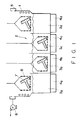
- a ceramic shell was formed on the surface of the pattern having dissipating property by means of an apparatus as shown in Fig.1.
- This apparatus had a condensing zone 2 on the upper side of the apparatus where water-cooled coils 1 were arranged and cooling water flowed and boiling zones 3a, 3b, 3c and 3d which were made by dividing the lower side of the apparatus.
- Four heat transfer heaters 4a, 4b, 4c and 4d for heating the boiling zones were arranged on the lower side of the boiling zones.
- An exhaust duct 5 was positioned at the top of the condensing zone. The exhaust duct sucked in vapor remaining not condensed by means of an exhaust fan 6.
- Cooling water of 10 °C was caused to flow through the water-cooled coils.
- 70 parts of methanol by weight and 30 parts of inorganic polysilazane by wieght were charged into the boiling zone 3a, 30 parts of methanol by weight, 50 parts of zircon flour of 130 meshes by weight and 20 parts of inorganic polysilazane by weight into the boiling zone 2b, 50 parts of methanol by weight and 50 parts of zircon sand of 325 meshes by weight into the boiling zone 3c, and 50 parts of methanol by weight and 50 parts of high-alumina sand of 0.3 to 0.7 mm in particle size into the boiling zone 3d.
- Electric heaters 3a, 3b, 3c and 3d were switched on in order that methanol can be constantly circulated by means of vaporization in the condensing zone and condensation in the condesing zone.
- the aforementioned pattern having a dissipating property as the base material 7 was put into a basket 8.
- the basket 8 with the pattern therein was hung in the condensing zone 2 and the pattern was preheated by vapor of methanol. After it had been confirmed that drops of solution condensed on the surface of the base material 7 and the bascket 8 were not observed, the basket 8 with the base material 7 therein was dipped into the boiling zone 3a and kept as it was in the boiling zone 3a for 3 sec. Then, the basket 8 with the base material 7 therein was lifted into the condensing zone 2 and dried in methanol vapor.
- the basket 8 with the base material 7 therein was dipped into the boiling zone 3b and kept as it was therein for 30 sec. Then, the basket with the base material therein was lifted into the condensing zone 3 and dried in vapor of methanol. The base material thus treated was dipped into the boiling zone 3c and kept as it was for 30 sec. The base material was lifted into the condensing zone 2 and dried therein. The dip of the base material into the boiling zones 3b and 3c was repeated twice. Subsequently, the dip of the treated base material into the boiling zone 3b for 3 sec. , the drying thereof in the condensing zone 2, the dip thereof into the boiling zone 3d for 30 sec.
- the base material thus treated was dipped into the boiling zone 3b and kept as it was for 3 sec., lifted into the condensing zone 2, dried therein and taken out of the condensing zone 2.
- the treated base material was put into an autoclave, kept as it was in an atmosphere of vapor of 6 atm. for 30 sec. and dewaxed.
- the treated base material was taken out of the autoclave. 10 mm of the top portion of the shaft was cut.
- a ceramic shell mold in which no paraffin remained, which had not any crack, entanglement 21 of bubbles and oozing of wax on the surface thereof and which had a film of uniform thickness and little irregularities was obtained.
- the thickness of the film was about 4 mm.
- Si3N4 was cast into this mold.
- 27.6 parts of fluid paraffin by weight and 3.0 parts of oleic acid by weight were added to 92.0 parts of Si3N4 of 0.7 ⁇ m in average particle size by weight, 6.0 parts of Y2O3 of 0.5 ⁇ m in average particle size by weight as sintering auxiliary, 2.0 parts of Al2O3 of 1.20 ⁇ m in average particle size by weight, and they were mixed and kneeded for 24 hours.
- a slurry obtained was exposed in a vacuum atmosphere to remove bubbles from the slurry. This slurry was cast into the aforementioned ceramic shell mold at a pressure of 3 kg/cm2.
- the slurry, with which the ceramic shell mold was filled up, was charged into a degreasing furnace together with the ceramic shell mold.
- the slurry was heated upto 500 °C at a rate of 3 °C per hour by circulating nitrogen gas in the degreasing furnace. After the slurry had been heated upto 500 °C, the slurry was kept as it was for 2 hours, naturally cooled as it was and the pressure inside the degreasing furnace was decreased to the atmospheric pressure.
- the slurry thus treated was taken out of the degreasing furnace, and the ceramic shell was removed from the treated slurry, by which a compact was obtained.
- the apparent density of the compact was 58% of a theoretical density.
- a film of glass powder for forming a gas-impermeable film was formed on the surface of the compact obtained in the Example-1 by using the apparatus as shown in Fig.1. Cooling water of 10°C was caused to flow through the water-cooled coils 1. 70 parts of methylene chloride by weight, 27 parts of boron nitride of 1.4 ⁇ m in average particle size by weight and 3 parts of inorganic polysilazane by weight were charged into the boiling zone 3a, 50 parts of methylene by weight, 40 parts of high-silicate glass ( SiO2 - 1.0 wt.% B2O3 - 0.5 wt.% Al2O3 ) of 3 ⁇ m in average particle size by weight and 10 parts of inorganic polysilazane by weight into the boiling zone 3b respectively. Then, the electric heater 4a and 4b were switched on in order that methylene chloride can be constantly circulated by means of the vaporization in the boiling zone and the condensation in the condensing zone.
- the aforementioned compact of silicon nitride as the base material 7 was put into a basket 8.
- the basket 8 with the base material 7 therein was hung in the condensing zone 2 on the boiling zone 3a and preheated by vapor of methylene chloride. After it had been confirmed that drops of solution condensed on the surface of the base material 7 and the basket 8 were not observed, the basket 8 with base material 7 therein was dipped into the boiling zone 3a and kept as it was in the boiling zone 3a for 30 sec. Then, the basket 8 with the base material 7 therein was lifted into the condensing zone 2 and dried there in vapor of methylene chloride. Then, the base material was dipped into the boiling zone 3b and kept as it was for 30 sec. and dried. Those operations were four times repeated. Thereafter, the base material was taken out of the apparatus. As a result, a film without any defect such as entanglement of bubbles and crack and with little irreguralities was formed on the surface of the base material.
- the base material thus treated was put into a HIP apparatus.
- the base material was heated upto 1300 °C by exhausting gas from the HIP apparatus, and nitrogen gas of 1 kg/cm2 ( hereinafter, represented by gauge pressure ) was supplied into the HIP apparatus.
- the base material was heated upto 1600°C and kept as it was for one hour. Until this moment, the pyrolysis of inorganic polysilazane, the generation of Si3N4 and the conversion of high-silicate glass to a gas-impermeable film due to softening of the high-silicate glass were carried out.
- gas began to be injected into the HIP apparatus under elevated pressure, the treated base material being kept therein at a temperature of 1600°C and the pressure of gas was increased upto 1700 kg/cm2. Further, the elevation of the pressure and the temperature was carried out in parallel. The pressure was elevated upto 2000 kg/cm2 and the temperature upto 1700°C . The base material was kept as it was at the aforementioned pressure and temperature. Then, the pressure was decreased and the base material was naturally cooled, by which the hot isostatic hydraulic pressing process finished.
- the film which was formed on the surface of the compact by means of the aforementioned method contributes to the formation of a highly-reliable gas-impermeable film.
- a film of a precursor of ceramics for forming a film resistant to oxidtion was formed on a sintered isotropic graphite body by using the apparatus as shown in Fig.1. Firstly, cooling water of 10°C was caused to flow through the water-cooled coils 1. 70 parts of methylene chloride by weight, 20 parts of silicon nitride of 0.25 ⁇ m in average particle size by weight and 10 parts of inorganic polysilazane by weight were charged into the boiling zone 3a. Then, the electric heater 4a was switched on so that methylene chloride can be constantly circulated by vaporization in the boiling zone 3a and condensation in the condensing zone 2.
- the sintered isotropic graphite body of 2.01 g/cm2 in apparent density was put into a basket 8, and the basket with said body therein was hung in the condensing zone 2 on the boiling zone 3a.
- the basket with the body was preheated by vapor of methylene chloride in the condensing zone 2. After it had been confirmed that solution drops on the surface of the base material and the basket 8 were not observed, the basket 8 with the base material 7 therein was dipped into the boiling zone 3a, kept for 30 sec., and dried in the condensing zone 2. After those operations had been 8 times repeated, the basket 8 with the base material 7 was taken out of the apparatus. As a result, a film which has not any defect such as entanglement of bubbles and crack and which has a smooth surface was formed.
- the base material having the aforementioned film was put into a heating furnace, heated upto 600 °C at a rate of 10 °C/min., kept as it was for one hour, and naturally cooled. Then, the base material was put into a sintering furnace, heated upto 1500 °C in an atmosphere of argon at a rate of 30 °C/min., kept as it was for 5 hours, and naturally cooled. As a result, a film of silicon carbide could be formed on the surface of the sintered body. This sintered body was kept at 1200°C in the atmosphere for 100 hours. Except that it was observed that the weight of the sintered body increased by only 0.21 wt.%, there was no change in the sintered body.
- the film of silicon carbide which was formed on the surface of the sintered isotropic graphite showed a very high resistance to oxidation.
Abstract
Description
- The present invention relates to a method for forming a ceramic film on the surface of a base material.
- There is a method for forming a compact by casting molten metal or slurry into a ceramic mold. It is known in this method that, after the surface of a pattern made from wax, polystyrene or urea has been coated with ceramic powder, said pattern is removed. Said pattern is dissipated by being heated and melted or by solvent extraction. A ceramic film, with which the pattern has been coated, is used for a mold. As the ceramic powder, mullite, zircon, fused silica or alumina is pointed out.
- A method wherein a porous compact is converted to a dense sintered body is disclosed in a Japanese Patent Publication Laid Open No. 146205/79. The surface of a compact made from metallic powder or ceramic powder is coated with ceramic powder. The compact having a film of ceramic powder on the surface thereof is heated and sintered. The film of ceramic powder is converted to a gas-impermeable dense film. The compact with said film is subjected to a hot isostatic hydraulic pressing process. As the ceramic powder, borosilicate glass, high-silicate glass, silica glass, silicon nitride, alumina or boron nitride is pointed out.
- It is also known that a film of ceramics or ceramic precursor is formed on the surface of a base material to change the surface properties of the base material.
- In those methods, ceramic powder is dispersed in water or organic solvent. A slurry thus prepared is regulated by adding inorganic or organic binder to the slurry if necessary. A pattern or a compact, which is dissipated by being heated and melted or by solvent extraction, is dipped into the slurry, and the surface of the pattern or the compact is coated with the slurry. After the pattern or the compact has been coated with the slurry, the pattern or the compact coated with the slurry is dried. It is also known that the coating of the pattern or the compact with the slurry and the dip of the pattern or the compact into the slurry are alternately carried out.
- In the method wherein the base material is dipped into the slurry, the ceramic powder insufficiently adheres to the base material, and the density of the film becomes unequal. On the other hand, in the case of dipping the base material into liquid of the precursor of ceramics, the precursor of ceramics insufficiently adheres to the base material, and air having adsorbed to the surface of the base material is taken in the film. In the case of dipping the base material whose surface is coated with slurry into a fluidized layer of ceramic powder, the density of the film becomes unequal because ceramic powder is liable to aggregate each other in the fluidized layer of ceramic powder. For the aforementioned reasons, a problem such that cracks are often generated on the surface of the base material at the successive step of heat treatment is pointed out.
- It is an object of the present invention to form a highly reliable film, in which cracks are not generated in the film formed on the surface of a base material by heat treatment.
- To attain the aforementioned object, the present invention provides a method for forming a ceramic film, comprising the steps of:
boiling a solution containing ceramics;
dipping a base material into said solution;
taking said base material out of said solution; and
drying said base material taken out of the solution. - The above object and other objects and advantages of the present invention will become apparent from the detailed desctiption which follows, taken in conjunction with the appended drawings.
- Fig.1 is a sectional view schematically illustrating an apparatus used in the present invention.
- In the preparation of a base material of the present invention, materials are selected in accord with the purpose of use of the materials, and said materials are formed into a predetermined shape.
- In the case of a pattern used for producing a ceramic shell mold, wax, polystyrene, urea or the like is used as material for making the pattern. Said pattern is formed into a shape of cavity for the mold. Said pattern is dissipated by being heated and melted or by the solvent extraction.
- When a gas-impermeable film is formed on the surface of a compact to subject a compact made from metallic powder or ceramic powder to a hot isostatic hydraulic pressing process, materials used for the compact are not specifically limited. In the case of metallic powders, as the base material, powders of ferroalloy such as powders of stainless steel and high-speed steel, powders of aluminium alloy, copper alloy, nickel alloy, cobalt alloy and molybdenum alloy are used. As ceramic powders, powders of oxides, nitrides, borides, oxides-nitrides or carbides-nitrides are used. As the nitrides, silicon nitride, aluminium nitride or titanium nitride is pointed out. As the carbides, silicon carbide, boron carbide or titanium carbide is used. As the borides, titanium diboride or zirconium diboride is used. As the oxynitride, SIALON is pointed out. As the carbo-nitride, titnium carbo-nitride is pointed out. Cermet such as alumina-nickel alloy or tungsten carbide-cobalt is used for matertial of a compact. Carbon materials such as isotropic graphite can be used for materials of a compact.
- Ceramics or a precursor of ceramics is used as materials for forming a film. The materials are selected in accord with the purpose of forming the film or the use of the film.
- In the case of making a ceramic shell mold, ceramic powder and binder are used. As the powder, powder of alumina, mullite, zircon or fused silica is used. As the binder, the precursor of ceramics such as hydrolysis solution of tetraethoxysilane, colloidal silica or the like is used.
- When a gas-impermeable film is formed on a compact of powders, glass or a precursor of ceramics is used as material for forming a film. As the glass, borosilicate glass, high-silicate glass or fused silica is pointed out. As the precusor of ceramics, the hydrolysis solution of tetraethoxysilane, colloidal silica or polysilazane is used.
- A film of ceramics is formed on the surface of the base material to make up for a defect of the base material. Materials for forming the film of ceramics are selected dependent on their objects and use. Starting materials can be ceramics or the precursor of ceramics. The starting materials can be in the form of powder or liquid. The starting materials are desired to be ceramics when the base material is ceramics.
- As the ceramic powders, oxides such as alumina, zirconia,mullite or yttria, nitrides such as silicon nitride, aluminium nitride or titanium nitride, carbides such as silicon carbide,boron carbide or titanium carbide, borides such as titanium diboride or zirconium diboride, oxynitride such as SIALON and titanium carbo-nitride are pointed out.
- The precursor of ceramics is one selected from the group consisting of precursors of oxides, silicon nitride and silicon carbide. As the precursor of oxides, tetraethoxysilane is used. As the precursor of silicon nitride, polysilazane is used. As the precursor of silicon carbide, polysilostyrene or polycarbosilane can be used.
- As an example wherein a film of ceramics is formed on the surface of a base material to make up for defects of the base material, an example wherein a film of silicon carbide resistant to oxidation is formed on the surface of a sintered carbon body and an example wherein a film of chromium carbide resistant to corrosion is formed on the surface of high-speed steel are pointed out.
- The particle size of ceramics and the particle size of the precursor of ceramics when it is used in the state of being dispersed are from about 0.2 to 500µm.
- A solvent having a boiling point of from about 20 to 150°C, in which ceramics or the precursor of ceramics is dispersed or dissolved, is desired. The solvent having a boiling point of from 20 to 60 °C is preferred. When the boiling point is less than 20°C,the temperature of a solution, into which ceramics or the precursor of ceramics is dispersed or dissolved, is fluctuated, being affected by an atmosphere in a room. The state of the solution at the boiling point is affected by the fluctuation of the temperature of the solvent, by which the state of the solution at the boiling point becomes hard to regulate. When the boiling point exceeds 150 °C , the base material is required to be heated upto a temperature over 150 °C. The base material can be impaired during this heating. Since the solvent is used in its state at the boiling point, a solvent having a high boiling point is not desirable.
- As the solvent, an azeotropic mixture of trichlorotrifluoroethane, an azeotropic mixture of tetrachlorodifluoroethane, trichloromonofluoromethane, trichloroethane, trichloroethylene, perchloroethylene, methylene chloride, benzene, toluene, xylene, methanol, ethanol or isopropanol is pointed out. As the azeotropic mixture of trichlorofluoroethane, azeotropic mixutures of trichlorotrifluoroethane with ethanol, methylene chloride, isopropanol or aceton is pointed out. As the azeotropic mixture of tetrachlorodifluoroethane, an azeotropic mixture of tetrachlorodifluoro-ethane with trichlorotrifluoroethane, isooctane or normal-propanol is pointed out.
- The concentration of ceramics or the precursor of ceramics which is dispersed or dissolved in the solvent is changed depending on the thikness of the film to be formed. The concentration is usually about 10 to 800 parts of ceramics or the precursor of ceramics by weight to 100 parts of the solvent by weight.
- The fluidity of the solvent can be regulated by adding a dispersant or a thickner to the solvent. As the dispersant, oleic acid is pointed out. As the thickner, polyvinylalcohol, polyvinylbutyral, methylcellulose, carboxymethylcellulose, ethylcellulose, paraffin wax or phenol resin is used.
- A plurality of solutions of various compositions can be prepared. The base material is dipped into one solution, then taken out of the solution and dried, Successively, the base material is dipped into other solution, then taken out of the solution and dried. A plurality of layers of various compositions can be formed on the surface of the base material by repeating operations such as those of dipping the base material into each of the solutions, taking the base material out of each of the solutions and drying the base material.
- The solutions, in which the ceramics or the precursor of ceramics are dispersed or dissolved, are used in the boiling state. The base material is dipped into the boiling solutions for a short period of time, that is, usually for 5 to 60 sec. The base material is dried after it has been dipped into the solutions and taken out of the solutions. It is unnecessary in the drying of the base material to perfectly remove the solvent from the base material. It is sufficient to remove the solvent from the base material to a predetermined degree. The degree of the drying of the base material is determined depending on the use of the base material.
- When the base material is dipped into boiling solution, a film having a uniform thickness and good adhesiveness is formed in comparison with the case where the base material is dipped into static solution or solution being stirred by an ordinary stirrer. This is because the solution or the slurry penetrates into minute concavities on the surface of the base material due to a strike of bubbles rising in the solution to the surface of the base material. In the case of the slurry, the aggregattion of powders is loosened by a climb motion of the bubbles, by which dispersion of the powders in the slurry is promoted. The dispersed powders form a layer of uniform density on the surface of the base material. Even when aggregated powders adhere to the film formed in layers, the aggregated powders are broken by the strike of the bubbles against the powders and removed.
- An apparatus to be used for the method of the present invention comprises a vessel, in which the solvents are put, and a heater for heating the solvents. A condenser for cooling and recovering vapor of the solvents is positioned above a boiling zone of the solvents inside the vessel. The condenser can be arranged inside the vessel, or the condenser can be put above the vessel which is made airtight and is connected to the vessel. When the vessel is made airtight, the vessel is required to have a structure, in which a compact can be put into the vessel and taken out of the vessel. The heater for heating the solvents can be positioned inside the vessel or outside the vessel. When the heater is put outside the vessel, the solvents should be circulated between the vessel and the heater.
- Paraffin wax having a melting point of 80 °C was melted into solution of 100 °C. Said solution was cast into a mold having a cavity. The cavity has a form, in which a shaft of 6 mm in diameter and 60 mm in length is connected to the center of a disk of 50 mm in diameter and 10 mm in thickness. After the solution inside the mold had been solidified, the mold was separated from the paraffin wax, by which a pattern made from the paraffin wax was obtained. Said pattern is dissipated by a treatment which will be described later.
- Subsequently, a ceramic shell was formed on the surface of the pattern having dissipating property by means of an apparatus as shown in Fig.1. This apparatus had a condensing
zone 2 on the upper side of the apparatus where water-cooled coils 1 were arranged and cooling water flowed and boilingzones heat transfer heaters exhaust fan 6. - Cooling water of 10 °C was caused to flow through the water-cooled coils. 70 parts of methanol by weight and 30 parts of inorganic polysilazane by wieght were charged into the boiling
zone 3a, 30 parts of methanol by weight, 50 parts of zircon flour of 130 meshes by weight and 20 parts of inorganic polysilazane by weight into the boiling zone 2b, 50 parts of methanol by weight and 50 parts of zircon sand of 325 meshes by weight into the boilingzone 3c, and 50 parts of methanol by weight and 50 parts of high-alumina sand of 0.3 to 0.7 mm in particle size into the boilingzone 3d.Electric heaters - The aforementioned pattern having a dissipating property as the
base material 7 was put into abasket 8. Thebasket 8 with the pattern therein was hung in the condensingzone 2 and the pattern was preheated by vapor of methanol. After it had been confirmed that drops of solution condensed on the surface of thebase material 7 and thebascket 8 were not observed, thebasket 8 with thebase material 7 therein was dipped into the boilingzone 3a and kept as it was in the boilingzone 3a for 3 sec. Then, thebasket 8 with thebase material 7 therein was lifted into the condensingzone 2 and dried in methanol vapor. Subsequently, thebasket 8 with thebase material 7 therein was dipped into the boilingzone 3b and kept as it was therein for 30 sec. Then, the basket with the base material therein was lifted into the condensing zone 3 and dried in vapor of methanol. The base material thus treated was dipped into the boilingzone 3c and kept as it was for 30 sec. The base material was lifted into the condensingzone 2 and dried therein. The dip of the base material into the boilingzones zone 3b for 3 sec. , the drying thereof in the condensingzone 2, the dip thereof into the boilingzone 3d for 30 sec. and the drying thereof in the condensingzone 2 were twice repeated respectively. The base material thus treated was dipped into the boilingzone 3b and kept as it was for 3 sec., lifted into the condensingzone 2, dried therein and taken out of the condensingzone 2. - After the aforementioned operations, the treated base material was put into an autoclave, kept as it was in an atmosphere of vapor of 6 atm. for 30 sec. and dewaxed. The treated base material was taken out of the autoclave. 10 mm of the top portion of the shaft was cut. As a result, a ceramic shell mold, in which no paraffin remained, which had not any crack, entanglement 21 of bubbles and oozing of wax on the surface thereof and which had a film of uniform thickness and little irregularities was obtained. The thickness of the film was about 4 mm.
- Subsequently, Si₃N₄ was cast into this mold. 27.6 parts of fluid paraffin by weight and 3.0 parts of oleic acid by weight were added to 92.0 parts of Si₃N₄ of 0.7µm in average particle size by weight, 6.0 parts of Y₂O₃ of 0.5µm in average particle size by weight as sintering auxiliary, 2.0 parts of Aℓ₂O₃ of 1.20 µm in average particle size by weight, and they were mixed and kneeded for 24 hours. A slurry obtained was exposed in a vacuum atmosphere to remove bubbles from the slurry. This slurry was cast into the aforementioned ceramic shell mold at a pressure of 3 kg/cm². The pressure, at which the slurry was cast into the mold, was temporarily decreased at the beginning of the casting. After it had been confirmed that the pressure was recovered to 3 kg/cm², the mold with the slurry therein was removed. Notwithstanding that the mold is filled up with the slurry, to which the pressure of 3 kg/cm² was applied during the casting, the mold had not any defect such as crack and oozing of the slurry. That is, the mold was in a sound state.
- The slurry, with which the ceramic shell mold was filled up, was charged into a degreasing furnace together with the ceramic shell mold. The slurry was heated upto 500 °C at a rate of 3 °C per hour by circulating nitrogen gas in the degreasing furnace. After the slurry had been heated upto 500 °C, the slurry was kept as it was for 2 hours, naturally cooled as it was and the pressure inside the degreasing furnace was decreased to the atmospheric pressure. The slurry thus treated was taken out of the degreasing furnace, and the ceramic shell was removed from the treated slurry, by which a compact was obtained. The apparent density of the compact was 58% of a theoretical density.
- A film of glass powder for forming a gas-impermeable film was formed on the surface of the compact obtained in the Example-1 by using the apparatus as shown in Fig.1. Cooling water of 10°C was caused to flow through the water-cooled coils 1. 70 parts of methylene chloride by weight, 27 parts of boron nitride of 1.4µm in average particle size by weight and 3 parts of inorganic polysilazane by weight were charged into the boiling
zone 3a, 50 parts of methylene by weight, 40 parts of high-silicate glass ( SiO₂ - 1.0 wt.% B₂O₃ - 0.5 wt.% Aℓ₂O₃ ) of 3 µm in average particle size by weight and 10 parts of inorganic polysilazane by weight into the boilingzone 3b respectively. Then, theelectric heater - The aforementioned compact of silicon nitride as the
base material 7 was put into abasket 8. Thebasket 8 with thebase material 7 therein was hung in the condensingzone 2 on the boilingzone 3a and preheated by vapor of methylene chloride. After it had been confirmed that drops of solution condensed on the surface of thebase material 7 and thebasket 8 were not observed, thebasket 8 withbase material 7 therein was dipped into the boilingzone 3a and kept as it was in the boilingzone 3a for 30 sec. Then, thebasket 8 with thebase material 7 therein was lifted into the condensingzone 2 and dried there in vapor of methylene chloride. Then, the base material was dipped into the boilingzone 3b and kept as it was for 30 sec. and dried. Those operations were four times repeated. Thereafter, the base material was taken out of the apparatus. As a result, a film without any defect such as entanglement of bubbles and crack and with little irreguralities was formed on the surface of the base material. - The base material thus treated was put into a HIP apparatus. The base material was heated upto 1300 °C by exhausting gas from the HIP apparatus, and nitrogen gas of 1 kg/cm² ( hereinafter, represented by gauge pressure ) was supplied into the HIP apparatus. The base material was heated upto 1600°C and kept as it was for one hour. Until this moment, the pyrolysis of inorganic polysilazane, the generation of Si₃N₄ and the conversion of high-silicate glass to a gas-impermeable film due to softening of the high-silicate glass were carried out.
- Successively, gas began to be injected into the HIP apparatus under elevated pressure, the treated base material being kept therein at a temperature of 1600°C and the pressure of gas was increased upto 1700 kg/cm². Further, the elevation of the pressure and the temperature was carried out in parallel. The pressure was elevated upto 2000 kg/cm² and the temperature upto 1700°C . The base material was kept as it was at the aforementioned pressure and temperature. Then, the pressure was decreased and the base material was naturally cooled, by which the hot isostatic hydraulic pressing process finished.
- Samples underwent sandblasting to remove the film on the surface of the base material. As a result, a dense compact having 99.5% of the theoretical density was obtained.
- As described above, it was understood that the film which was formed on the surface of the compact by means of the aforementioned method contributes to the formation of a highly-reliable gas-impermeable film.
- A film of a precursor of ceramics for forming a film resistant to oxidtion was formed on a sintered isotropic graphite body by using the apparatus as shown in Fig.1. Firstly, cooling water of 10°C was caused to flow through the water-cooled coils 1. 70 parts of methylene chloride by weight, 20 parts of silicon nitride of 0.25 µm in average particle size by weight and 10 parts of inorganic polysilazane by weight were charged into the boiling
zone 3a. Then, theelectric heater 4a was switched on so that methylene chloride can be constantly circulated by vaporization in the boilingzone 3a and condensation in the condensingzone 2. - The sintered isotropic graphite body of 2.01 g/cm² in apparent density was put into a
basket 8, and the basket with said body therein was hung in the condensingzone 2 on the boilingzone 3a. The basket with the body was preheated by vapor of methylene chloride in the condensingzone 2. After it had been confirmed that solution drops on the surface of the base material and thebasket 8 were not observed, thebasket 8 with thebase material 7 therein was dipped into the boilingzone 3a, kept for 30 sec., and dried in the condensingzone 2. After those operations had been 8 times repeated, thebasket 8 with thebase material 7 was taken out of the apparatus. As a result, a film which has not any defect such as entanglement of bubbles and crack and which has a smooth surface was formed. - The base material having the aforementioned film was put into a heating furnace, heated upto 600 °C at a rate of 10 °C/min., kept as it was for one hour, and naturally cooled. Then, the base material was put into a sintering furnace, heated upto 1500 °C in an atmosphere of argon at a rate of 30 °C/min., kept as it was for 5 hours, and naturally cooled. As a result, a film of silicon carbide could be formed on the surface of the sintered body. This sintered body was kept at 1200°C in the atmosphere for 100 hours. Except that it was observed that the weight of the sintered body increased by only 0.21 wt.%, there was no change in the sintered body.
- As described above, the film of silicon carbide which was formed on the surface of the sintered isotropic graphite showed a very high resistance to oxidation.
Claims (22)
boiling a solution containing ceramics;
dipping a base material into said solution;
taking said base material out of said solution; and
drying said base material taken out of the solution.
Applications Claiming Priority (2)
| Application Number | Priority Date | Filing Date | Title |
|---|---|---|---|
| JP1252644A JPH03115586A (en) | 1989-09-28 | 1989-09-28 | Formation of ceramic film |
| JP252644/89 | 1989-09-28 |
Publications (2)
| Publication Number | Publication Date |
|---|---|
| EP0420187A2 true EP0420187A2 (en) | 1991-04-03 |
| EP0420187A3 EP0420187A3 (en) | 1992-04-22 |
Family
ID=17240221
Family Applications (1)
| Application Number | Title | Priority Date | Filing Date |
|---|---|---|---|
| EP19900118469 Withdrawn EP0420187A3 (en) | 1989-09-28 | 1990-09-26 | Method for forming a ceramic film |
Country Status (3)
| Country | Link |
|---|---|
| US (1) | US5091222A (en) |
| EP (1) | EP0420187A3 (en) |
| JP (1) | JPH03115586A (en) |
Cited By (2)
| Publication number | Priority date | Publication date | Assignee | Title |
|---|---|---|---|---|
| FR2685693A1 (en) * | 1991-12-30 | 1993-07-02 | Europ Propulsion | PROCESS FOR PRODUCING PROTECTION AGAINST OXIDATION OF COMPOSITE MATERIAL PRODUCTS, AND PRODUCTS THUS PROTECTED. |
| EP1386983A1 (en) * | 2002-07-31 | 2004-02-04 | ItN-Nanovation GmbH | Ceramic coating for a boiler |
Families Citing this family (5)
| Publication number | Priority date | Publication date | Assignee | Title |
|---|---|---|---|---|
| FR2700773B1 (en) * | 1993-01-28 | 1995-03-03 | Pechiney Recherche | Coatings for protecting materials against reactions with the atmosphere at high temperature. |
| US6001425A (en) * | 1997-07-08 | 1999-12-14 | Northrop Grumman Corporation | Ceramic RAM film coating process |
| US7445814B2 (en) * | 2003-10-22 | 2008-11-04 | Hewlett-Packard Development Company, L.P. | Methods of making porous cermet and ceramic films |
| JP4784732B2 (en) * | 2005-08-15 | 2011-10-05 | 独立行政法人産業技術総合研究所 | Narrow diameter channel tube and method for manufacturing the same |
| JP2019082275A (en) * | 2017-10-30 | 2019-05-30 | イビデン株式会社 | Geothermal power generation pipe |
Citations (10)
| Publication number | Priority date | Publication date | Assignee | Title |
|---|---|---|---|---|
| FR988237A (en) * | 1948-06-12 | 1951-08-24 | Philips Nv | Manufacturing process of ceramic objects |
| US2885366A (en) * | 1956-06-28 | 1959-05-05 | Du Pont | Product comprising a skin of dense, hydrated amorphous silica bound upon a core of another solid material and process of making same |
| FR2018922A1 (en) * | 1968-09-26 | 1970-06-26 | Allegheny Ludlum Steel | |
| EP0134769A2 (en) * | 1983-07-28 | 1985-03-20 | Union Carbide Corporation | Oxidation prohibitive coatings for carbonaceous articles |
| US4582733A (en) * | 1982-06-30 | 1986-04-15 | Mccord James W | Method for cleaning and coating objects |
| US4842888A (en) * | 1988-04-07 | 1989-06-27 | Dow Corning Corporation | Ceramic coatings from the pyrolysis in ammonia of mixtures of silicate esters and other metal oxide precursors |
| EP0344011A1 (en) * | 1988-05-27 | 1989-11-29 | Ngk Insulators, Ltd. | Inorganic porous membrane |
| FR2637587A1 (en) * | 1988-10-12 | 1990-04-13 | Dipsol Chem | PROCESS FOR FORMING A CERAMIC COATING BY IRRADIATION BY A LASER BEAM |
| US4921731A (en) * | 1986-02-25 | 1990-05-01 | University Of Florida | Deposition of ceramic coatings using sol-gel processing with application of a thermal gradient |
| US4927673A (en) * | 1988-01-27 | 1990-05-22 | Buntrock Industries, Inc. | Rapid technique for making improved laminar ceramic shell molds using a phosphate modified aluminum salt binder |
Family Cites Families (2)
| Publication number | Priority date | Publication date | Assignee | Title |
|---|---|---|---|---|
| SE414920C (en) * | 1978-05-02 | 1982-03-04 | Asea Ab | SET TO MAKE A FORM OF A MATERIAL IN THE FORM OF A POWDER THROUGH ISOSTATIC PRESSING OF A POWDER-FORMATED BODY |
| US4911992A (en) * | 1986-12-04 | 1990-03-27 | Dow Corning Corporation | Platinum or rhodium catalyzed multilayer ceramic coatings from hydrogen silsesquioxane resin and metal oxides |
-
1989
- 1989-09-28 JP JP1252644A patent/JPH03115586A/en active Pending
-
1990
- 1990-09-24 US US07/586,801 patent/US5091222A/en not_active Expired - Fee Related
- 1990-09-26 EP EP19900118469 patent/EP0420187A3/en not_active Withdrawn
Patent Citations (10)
| Publication number | Priority date | Publication date | Assignee | Title |
|---|---|---|---|---|
| FR988237A (en) * | 1948-06-12 | 1951-08-24 | Philips Nv | Manufacturing process of ceramic objects |
| US2885366A (en) * | 1956-06-28 | 1959-05-05 | Du Pont | Product comprising a skin of dense, hydrated amorphous silica bound upon a core of another solid material and process of making same |
| FR2018922A1 (en) * | 1968-09-26 | 1970-06-26 | Allegheny Ludlum Steel | |
| US4582733A (en) * | 1982-06-30 | 1986-04-15 | Mccord James W | Method for cleaning and coating objects |
| EP0134769A2 (en) * | 1983-07-28 | 1985-03-20 | Union Carbide Corporation | Oxidation prohibitive coatings for carbonaceous articles |
| US4921731A (en) * | 1986-02-25 | 1990-05-01 | University Of Florida | Deposition of ceramic coatings using sol-gel processing with application of a thermal gradient |
| US4927673A (en) * | 1988-01-27 | 1990-05-22 | Buntrock Industries, Inc. | Rapid technique for making improved laminar ceramic shell molds using a phosphate modified aluminum salt binder |
| US4842888A (en) * | 1988-04-07 | 1989-06-27 | Dow Corning Corporation | Ceramic coatings from the pyrolysis in ammonia of mixtures of silicate esters and other metal oxide precursors |
| EP0344011A1 (en) * | 1988-05-27 | 1989-11-29 | Ngk Insulators, Ltd. | Inorganic porous membrane |
| FR2637587A1 (en) * | 1988-10-12 | 1990-04-13 | Dipsol Chem | PROCESS FOR FORMING A CERAMIC COATING BY IRRADIATION BY A LASER BEAM |
Non-Patent Citations (1)
| Title |
|---|
| JOURNAL OF NON-CRYSTALLINE SOLIDS,VOL.63,NO 1/2,FEBRUARY 1984,AMSTERDAM, S. SAKKA "FORMATION OF SHEETS AND COATING FILMS FROM ALKOXIDE SOLUTIONS" & P. 223-235 * |
Cited By (6)
| Publication number | Priority date | Publication date | Assignee | Title |
|---|---|---|---|---|
| FR2685693A1 (en) * | 1991-12-30 | 1993-07-02 | Europ Propulsion | PROCESS FOR PRODUCING PROTECTION AGAINST OXIDATION OF COMPOSITE MATERIAL PRODUCTS, AND PRODUCTS THUS PROTECTED. |
| EP0550305A1 (en) * | 1991-12-30 | 1993-07-07 | Societe Europeenne De Propulsion | Method of protecting a composite material against oxidation, and products protected in this way |
| US5622751A (en) * | 1991-12-30 | 1997-04-22 | Societe Europeenne De Propulsion | Method of protecting products of composite material against oxidizing and products protected thereby |
| EP1386983A1 (en) * | 2002-07-31 | 2004-02-04 | ItN-Nanovation GmbH | Ceramic coating for a boiler |
| WO2004013378A1 (en) * | 2002-07-31 | 2004-02-12 | Itn-Nanovation Gmbh | Ceramic coating for combustion boilers |
| CN100354455C (en) * | 2002-07-31 | 2007-12-12 | Itn纳诺瓦圣股份公司 | Ceramic coating for a combustion boiler |
Also Published As
| Publication number | Publication date |
|---|---|
| EP0420187A3 (en) | 1992-04-22 |
| JPH03115586A (en) | 1991-05-16 |
| US5091222A (en) | 1992-02-25 |
Similar Documents
| Publication | Publication Date | Title |
|---|---|---|
| CN107814591B (en) | Preparation method of boride modified silicon-based antioxidant coating on surface of carbon material | |
| EP0419682A1 (en) | Method of producing ceramic sinter having dense ceramic coating | |
| RU2176628C2 (en) | Composite material (variants) and method or preparing thereof, method of treating fibrous semi-finished product (variants) | |
| CA1163809A (en) | Process for the manufacture of substantially pore- free shaped polycrystalline articles by isostatic hot-pressing in glass casings | |
| US4966201A (en) | Transfer tube | |
| US5900277A (en) | Method of controlling infiltration of complex-shaped ceramic-metal composite articles and the products produced thereby | |
| GB2121777A (en) | Production of corrosion and erosion resistant solid carbon articles | |
| US4159353A (en) | Platinum coating dense refractories | |
| US5091222A (en) | Method for forming a ceramic film | |
| JPH0789779A (en) | Self-recovery function coating material and its production | |
| EP0407786A1 (en) | Transfer tube with insitu heater | |
| US5004629A (en) | Transfer tube | |
| GB2232971A (en) | Molten metal transfer tube. | |
| US4935199A (en) | Process for producing high density sintered body | |
| US4843043A (en) | Method for manufacturing a sintered body with high density | |
| JP4171916B2 (en) | Heat-resistant covering material | |
| US5022150A (en) | Method for producing heat transfer tube with insitu heater | |
| EP0354376A1 (en) | Process for producing high density sintered body | |
| US4978039A (en) | Transfer tube with insitu heater | |
| EP0351113B1 (en) | Fiber-reinforced and particle-dispersion reinforced mullite composite material and method of producing the same | |
| US5226470A (en) | Expendable ceramic mandrel | |
| JP2968477B2 (en) | Method for producing non-oxide ceramic fiber reinforced ceramic composite material | |
| JP2002513731A (en) | Ceramic composite | |
| WO1997019201A1 (en) | Process for making complex-shaped ceramic-metal composite articles | |
| EP1435501A1 (en) | Heat-resistant coated member |
Legal Events
| Date | Code | Title | Description |
|---|---|---|---|
| PUAI | Public reference made under article 153(3) epc to a published international application that has entered the european phase |
Free format text: ORIGINAL CODE: 0009012 |
|
| 17P | Request for examination filed |
Effective date: 19901004 |
|
| AK | Designated contracting states |
Kind code of ref document: A2 Designated state(s): DE FR GB |
|
| PUAL | Search report despatched |
Free format text: ORIGINAL CODE: 0009013 |
|
| AK | Designated contracting states |
Kind code of ref document: A3 Designated state(s): DE FR GB |
|
| 17Q | First examination report despatched |
Effective date: 19930210 |
|
| RBV | Designated contracting states (corrected) |
Designated state(s): DE |
|
| STAA | Information on the status of an ep patent application or granted ep patent |
Free format text: STATUS: THE APPLICATION IS DEEMED TO BE WITHDRAWN |
|
| 18D | Application deemed to be withdrawn |
Effective date: 19940726 |