EP0419185A2 - Conveying rotational member for an ink recording apparatus - Google Patents
Conveying rotational member for an ink recording apparatus Download PDFInfo
- Publication number
- EP0419185A2 EP0419185A2 EP90310157A EP90310157A EP0419185A2 EP 0419185 A2 EP0419185 A2 EP 0419185A2 EP 90310157 A EP90310157 A EP 90310157A EP 90310157 A EP90310157 A EP 90310157A EP 0419185 A2 EP0419185 A2 EP 0419185A2
- Authority
- EP
- European Patent Office
- Prior art keywords
- recording
- ink
- recording medium
- spur
- recording apparatus
- Prior art date
- Legal status (The legal status is an assumption and is not a legal conclusion. Google has not performed a legal analysis and makes no representation as to the accuracy of the status listed.)
- Granted
Links
Images


Classifications
-
- B—PERFORMING OPERATIONS; TRANSPORTING
- B41—PRINTING; LINING MACHINES; TYPEWRITERS; STAMPS
- B41J—TYPEWRITERS; SELECTIVE PRINTING MECHANISMS, i.e. MECHANISMS PRINTING OTHERWISE THAN FROM A FORME; CORRECTION OF TYPOGRAPHICAL ERRORS
- B41J13/00—Devices or arrangements of selective printing mechanisms, e.g. ink-jet printers or thermal printers, specially adapted for supporting or handling copy material in short lengths, e.g. sheets
- B41J13/02—Rollers
- B41J13/076—Construction of rollers; Bearings therefor
-
- B—PERFORMING OPERATIONS; TRANSPORTING
- B41—PRINTING; LINING MACHINES; TYPEWRITERS; STAMPS
- B41J—TYPEWRITERS; SELECTIVE PRINTING MECHANISMS, i.e. MECHANISMS PRINTING OTHERWISE THAN FROM A FORME; CORRECTION OF TYPOGRAPHICAL ERRORS
- B41J2/00—Typewriters or selective printing mechanisms characterised by the printing or marking process for which they are designed
- B41J2/005—Typewriters or selective printing mechanisms characterised by the printing or marking process for which they are designed characterised by bringing liquid or particles selectively into contact with a printing material
- B41J2/01—Ink jet
-
- B—PERFORMING OPERATIONS; TRANSPORTING
- B41—PRINTING; LINING MACHINES; TYPEWRITERS; STAMPS
- B41F—PRINTING MACHINES OR PRESSES
- B41F22/00—Means preventing smudging of machine parts or printed articles
-
- B—PERFORMING OPERATIONS; TRANSPORTING
- B65—CONVEYING; PACKING; STORING; HANDLING THIN OR FILAMENTARY MATERIAL
- B65H—HANDLING THIN OR FILAMENTARY MATERIAL, e.g. SHEETS, WEBS, CABLES
- B65H27/00—Special constructions, e.g. surface features, of feed or guide rollers for webs
-
- B—PERFORMING OPERATIONS; TRANSPORTING
- B65—CONVEYING; PACKING; STORING; HANDLING THIN OR FILAMENTARY MATERIAL
- B65H—HANDLING THIN OR FILAMENTARY MATERIAL, e.g. SHEETS, WEBS, CABLES
- B65H2404/00—Parts for transporting or guiding the handled material
- B65H2404/10—Rollers
- B65H2404/11—Details of cross-section or profile
- B65H2404/111—Details of cross-section or profile shape
- B65H2404/1115—Details of cross-section or profile shape toothed roller
-
- B—PERFORMING OPERATIONS; TRANSPORTING
- B65—CONVEYING; PACKING; STORING; HANDLING THIN OR FILAMENTARY MATERIAL
- B65H—HANDLING THIN OR FILAMENTARY MATERIAL, e.g. SHEETS, WEBS, CABLES
- B65H2404/00—Parts for transporting or guiding the handled material
- B65H2404/10—Rollers
- B65H2404/11—Details of cross-section or profile
- B65H2404/114—Built-up elements
- B65H2404/1141—Built-up elements covering a part of the periphery
-
- B—PERFORMING OPERATIONS; TRANSPORTING
- B65—CONVEYING; PACKING; STORING; HANDLING THIN OR FILAMENTARY MATERIAL
- B65H—HANDLING THIN OR FILAMENTARY MATERIAL, e.g. SHEETS, WEBS, CABLES
- B65H2404/00—Parts for transporting or guiding the handled material
- B65H2404/10—Rollers
- B65H2404/13—Details of longitudinal profile
- B65H2404/131—Details of longitudinal profile shape
- B65H2404/1312—Details of longitudinal profile shape tapered shape
-
- B—PERFORMING OPERATIONS; TRANSPORTING
- B65—CONVEYING; PACKING; STORING; HANDLING THIN OR FILAMENTARY MATERIAL
- B65H—HANDLING THIN OR FILAMENTARY MATERIAL, e.g. SHEETS, WEBS, CABLES
- B65H2404/00—Parts for transporting or guiding the handled material
- B65H2404/10—Rollers
- B65H2404/15—Roller assembly, particular roller arrangement
- B65H2404/153—Arrangements of rollers facing a transport surface
- B65H2404/1531—Arrangements of rollers facing a transport surface the transport surface being a cylinder
Definitions
- This invention relates to a rotational member for conveying a recording medium such as paper, film or synthetic paper consisting thereof in a recording apparatus for effecting recording using ink on the recording medium, and to a recording apparatus provided with the same. More particularly, this invention relates to a recording apparatus having a rotational member whose peripheral surface as discharge means for discharging the recording medium after recording continuously bears against the recording medium. Particularly effectively, this invention relates to an ink jet recording apparatus for discharging recording liquid to a recording medium (preferably by the use of heat energy) to thereby accomplish recording, and particularly to a conveying system for the recording medium in a recording medium conveying mechanism applied therein.
- recording apparatuses using the ink jet system or the bubble jet system have generally been used as recording apparatuses such as facsimile apparatuses and printers for their small noise during operation and the simplicity and inexpensiveness of their basic mechanical structure.
- apparatuses which are compelled to convey a recording medium with the printed surface thereof bearing against a recording head find a solution thereto in the provision of a special recording medium or special fixating means, specifically, the use of not plain paper but paper exclusively for ink jet represented by coat paper of good fixativeness or the like, and further the mounting of a heat source such as a fixating device for expediting the desiccation of ink.
- a heat source such as a fixating device for expediting the desiccation of ink.
- the ink absorbing ability is very high and originally it is difficult for a problem to appear, but under a high humidity environment, a similar problem arises.
- this type cannot cope with various recording mediums such as postcards, cut paper and OHP film, and does not meet the needs of the market which demands plain paper recording.
- the addition of the fixating device leads to a high cost, and to complete fixation within a short time to achieve the purpose by only fixation, a very high temperature heating process is required and complication of the apparatus is unavoidable. In this case, the occurrence of the unsatisfactory conveyance of the recording medium would pose the problem that before the quality of image, the medium itself is deteriorated.
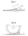
- the spur has usually been of such a star shape as shown in Figure 10 of the accompanying drawings wherein the peripheral surface thereof bearing against the recording medium is a discontinuous peripheral surface having thin and sharply pointed teeth so that the area of contact with the printed surface of the recording medium may be decreased as much as possible and the transferable area may be decreased to the utmost to thereby reduce the probability with the spur touches printed lines or characters and also, even when ink has been transferred to the spur, the spur may be rotated to cause the transferred ink to be re-transferred to thereby reduce the amount of ink which will stain the printed surface to the utmost.
- a roller characterized in that the peripheral surface thereof is of a shape in which it continuously bears against the recording medium, whereby even before ink on the surface of the recording medium is fixated in principle, the ink may not be transferred onto the spur and the compatibility of conveyance and printing free of the spur trace is made possible.
- the balance of power with which the ink may or may not adhere is determined by the surface bonding power between the spur and the ink, the bonding power between the ink and paper and the cohesive power of the ink itself and by making such design that when the spur moves, the force with which the ink adheres to the spur is always made lower by using the shape of the present invention which utilizes the characteristic of this balance of power, whereby non-transfer of the ink to the spur can be achieved.
- the present invention it also becomes possible to give a degree of freedom to the design of the recording apparatus and feed the recording medium after recording back to a recording station, and recording good in quality of image can also be accomplished even if slight heat is imparted for heating and fixation.
- the reference numeral 1 designates a cartridge comprising a recording head 1a and an ink tank 1b which are made integral with each other
- the reference numeral 2 denotes a carriage for scanning in the subscanning direction with the cartridge 1 carried thereon
- the reference numeral 3 designates the guide shaft of the carriage 2
- the reference numeral 4 denotes the chassis of the base of the apparatus.
- the reference numeral 5 designates a conveying platen roller
- the reference numerals 6 and 7 denote conveying rollers.
- the reference numeral 8 designates a spur according to an embodiment of the present invention.
- the spur 8 is of a shape as shown in Figure 2 and Figure 3 which is a side view corresponding to Figure 2.
- the reference numeral 9 denotes a conveyance guide.
- P designates a recording medium.
- the reference numeral 10 in Figure 8 denotes ink discharged onto the recording medium.
- the reference numeral 11 in Figure 10 designates a spur according to the prior art, and Figure 10 shows the transfer process of ink to the prior-art spur.
- the recording head 1a is provided with a plurality of liquid paths filled with well-known liquid (ink).
- the ink filling these liquid paths is balanced in its surface tension and external pressure on the orifice surface in its steady state.
- Electro-thermal converting members are disposed in said plurality of liquid paths, and at least one driving signal for providing a rapid temperature rise beyond nuclear boiling is applied to these electro-thermal converting members to thereby generate heat energy and gasify the adjacent ink, thus causing film boiling.
- a bubble corresponding to the driving signal is formed in the ink, and by the growth of this bubble, the ink may be discharged from the orifice surface to the recording medium P.
- the bubble is cooled by the ink and contracts, and ink is supplied from the ink tank 1b into the liquid paths by capillary phenomenon.
- the ink By growing or contracting a bubble in the liquid paths filled with the ink as described above, the ink can be discharged from the orifice surface to form a liquid droplet. Accordingly, when the driving signal is applied in a pulse form to the electro-thermal converting members in conformity with image information, the growth and contraction of the bubble takes place in a moment, and the ink can be discharged from the orifice surface of the recording head 1a to the recording medium P to thereby accomplish recording.
- the recording medium P is first made to pass between the conveying roller 5 and the rollers 6, 7, and is set until it arrives at between the spur 8 and the guide member 9.
- the ink cartridge 1 containing the recording head 1a therein is moved in the sub-scanning direction of the carriage 2 and also the ink is discharged from the orifice surface of the recording head 1a onto the recording medium P in conformity with recording information, whereby recording is effected.
- the conveying roller 5 is rotatively driven to convey the recording medium P by one line in the main scanning direction (the direction of arrow A). At this time, the recording medium P is conveyed while being held by the spur 8 and the guide member 9.
- the spur 8 which directly contacts with the printing surface of the recording medium is of such structure that as shown in Figure 3, a spur (like a counter of an abacus) formed of silicone resin whose peripheral surface 80 is of a rotational shape continuously bearing against the recording medium and which, in the front view of Figure 2, has both-side tapers symmetrically at an angle ⁇ .
- the spur can continuously accomplish substantially point contact, and irrespective of the scanning direction of the recording medium, can prevent recorded images from being disturbed even if the spur rubs against the unfixated recording surface.
- Figure 9 shows a state in which the recording medium P has begun to more forward in the main scanning direction from the state of Figure 8 and the spur 8 has begun to effect relative movement at the point of contact.
- the ink adheres to the surface of the spur at the adherence energy level between the spur and the ink and therefore assumes a more protuberent shape than in the stationary state when it is stripped off by the rotation of the spur.
- the shape at that time is a flared shape with the protuberant point as the vertex.
- the peripheral surface of the spur 8 is a continuous surface and when the ink 10 has been dragged up in proportion to its adhering force relative to the spur 8, the cohesive power by the surface tension of the ink which tends to reduce the flared protuberance of the ink itself to thereby reduce the surface area becomes stronger and further, the underside of the ink 10 is restrained by the adhering force of the ink and the recording medium P over a large area, with a result that the ink is dragged down while sliding toward the recording medium P.
- the ink can be used without being transferred onto the spur 8.
- the peripheral surface of the spur was a discontinuous surface, said balance of force would be momentarily destroyed and thus, the ink would be left on the spur.
- An extreme example of it is the example of the prior art shown in Figure 10.
- the force with which the adhering ink is continuously dragged down would be continuous as in the present embodiment and flared protuberances would be small and created at individual points of contact and the ink would be raised substantially vertically from the printing surface, and a constriction would be created between the ink 10-b on the edge portion of the spur 11 and the ink 10-a on the recording medium P and at last, the step area of the constricted part would become smallest and thus weakest, and the constricted part would be cut by the cohesive power provided by the surface tension of the ink 10-a and the ink 10-b. Therefore, in principle, the ink would be transferred onto the spur 11.
- Table 1 below shows a test in which use has been made of a spur having the shape as shown in Figure 2 and in which the angle ⁇ formed by the tapered portion with respect to the printing surface is 80° and the contact pressure to the surface of the recording medium is set to 20 g and samples differing in the water-repelling property of the surface have been used under environments of different humidities to effect home feed immediately after a solid black line has been printed, to thereby examine whether a spur trace has appeared.
- Table 2 below shows a similar test carried out for the shape of Figure 10 and under the same other conditions.
- Table 4 shows a test in which, relative to the test shown in Table 1, use has been made of a spur having a water-repelling property of 110° and the angle formed by the tapered portion with respect to the printing surface has been varied.
- the test of the water-repelling property has been carried out with the angle of contact with water as a standard parameter.
- the test of the contact pressure is shown in terms of the total pressure per spur with respect to the printing surface.
- Tables 1 to 4 are test data including the tests on the present embodiment and the prior art carried out in the aforedescribed form of test.
- the spur in the present invention may pass over unfixated ink under high humidity because the ink will not originally be transferred to the spur due to the aforedescribed principle even if the spur is rolled in the ink liquid. It is considered to be because a boundary line between good and bad by the parameter of the water repelling property has been in the vicinity of the angle of contact 30° in the setting of the present embodiment that in Table 1, NG appears at the angle of contact 30° under high humidity. In any case, it can be understood from the comparison between Table 1 and 2 that the disadvantage peculiar to the prior-art spur is solved by one or more ranks.
- Table 3 shows a test in which the surface roughness of the spur has been varied in the embodiment according to the system of the present invention, and here, for the sake of convenience, the numerical values at Rmax are used as parameters, but again, smaller surface roughness results in good sliding and reduced resistance and therefore, the force with which the ink is dragged down may be small, and this is better.
- the surface roughness differs in its shape from material to material although equal in numerical value, and particularly whether the surface roughness is good or bad is determined by the combination thereof with the adhering force provided by the water-repelling property.
- Table 4 shows the variations by the angle formed by the spur with respect to the printing surface, and again, an angle an approximate as possible to vertical with respect to the printing surface has led to a good result. This is because a stripping-off force is applied in a direction perpendicular to the printing surface when the ink is dragged down from the spur, and it is proved that greater ease with which the force in this direction is applied leads to a better result.
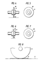
- Figures 4 and 5 showing a member whose peripheral surface is semicircular ( ⁇ can be regarded as 45°) and Figures 6 and 7 showing a member which can be regarded as a half of Figure 2 show further embodiments of the present invention.
- the peripheral surface continuously bears against the surface of the recording medium, and so far as this is concerned, the peripheral surface need not be circular, but may be polygonal or elliptical or of an indefinite shape such as a belt-like shape, and in short, the peripheral surface can be of a continuous shape in which it is continuous without the contact thereof with the ink being discontinued near the point of contact therebetween.
- the balance of power with which the ink does or does not adhere is determined by the bonding power between the spur and the ink, the bonding power between the ink and the paper and the cohesive power by the surface tension of the ink itself, and the characteristic of this balance of power is utilized. It has been found in the present invention that by using a shape in which even the width of the spur is prescribed as in the present invention, the force with which the ink adheres to the spur when the spur moves is made so as to become always lower in any case, whereby complete non-transfer of the ink to the spur can be achieved.
- the recording medium such as paper and this rotational member are microscopically deformed in a state in which they are in contact with each other by pressure applied thereto, and the definition becomes indefinite as to also a spur whose end surface is originally R-shaped and therefore, the width is defined by the width in the cross-setion passing the rotational axis 0.1 mm inward from the peripheral surface which bears against the recording medium.
- width W1 indicates the width of restraint between the surface of the recording medium and the ink.
- Table 5 below shows a test in which in the case of a spur having the shape of Figure 2 and having an angle of 80° formed by the tapered portion with respect to the printing surface, the contact pressure to the surface of the paper has been set to 20 g and samples differing in the width of the end have been home-fed immediately after a solid black line has been printed under environments differing in humidity, to thereby examine whether said one point of spur trace has appeared.
- the production of said one point of spur trace could also be prevented by selecting the width W of the spur 8 of the above-described shape to 1.0 mm or less, optimally 0.7 mm or less.
- the width W i.e., 0.7 mm or less
- those within a preferable range under the conditions of Tables 1, 3 and 4 shown above are optimum, and have also confirmed that a good result in practical use can be obtained even if the angle 8 of Table 4 is made small (e.g. 30°).
- Preferred examples of the material having a high water-repelling property include tetrafluoroethylene resin, parfluoro-alkoxy resin, propylene hexafluoride copolymer resin, tetrafluoroethylene-ethylene copolymer resin, vinylidene fluoride resin and ethylene chloride trifluoride resin which are fluorine compound materials generally used, polymers such as high-density polyethylene, polyethylene, polypropylene, trimethyl pentene, polyacetal, nylon, polysulphone and phenol, and members having their surfaces coated with those polymers. Basically, the choice among these materials is determined with the water-repelling property, the ink-resisting property, abrasion and deformation strength being additionally taken into account.
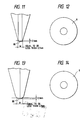
- Figures 11 and 12 and Figures 13 and 14 show further embodiments of the present invention.
- Figures 11 and 12 are enlarged views of the end portion, Figure 11 showing a spur of which the corner portion is R-shaped.
- Figure 12 shows a spur of a shape equivalent to an R-shape including the surface of contact.
- the peripheral surface need not be circular, but may be polygonal or elliptical or of an indefinite shape such as a belt-like shape, and in short, the peripheral surface can be of a continuous shape in which it is continuous without the contact thereof with the ink being discontinued near the point of contact therebetween.
- the spur of the present invention is best suited, and in an apparatus wherein more or less stain is approved, the spur of the invention previously described with reference to Figures 1 to 9 can be said to be best suited from the viewpoint of durability or the like. In any case, the present embodiment exhibits a considerably better level than the previously described invention.
- This embodiment in which the rotational member is constituted by a film member having a water repelling property, has the advantage that the working process can be simplified and mass production of rotational members is made possible by press working of good productivity. Also, the mass production can be accomplished by minimally using the expensive water-repelling member and therefore, a lower cost can be realized.
- Figures 19A and 19B are a front view and a side view, respectively, of a spur, and Figure 20 is an illustration showing the assembled construction of the spur.
- the spur 8 is comprised of a ring 8a provided by press-working a water-repellent member such as tetrafluoroethylene film into a ring shape, a molded member 8d of polyethylene, polyacetal or like material comprising a shaft 8e and a guide ring 8b for the ring 8a molded integrally with each other, and a guide ring 8c for the ring 8a, the molded member 8a and the guide ring 8c being integrally mounted on both sides of the ring 8a.
- a water-repellent member such as tetrafluoroethylene film into a ring shape
- a molded member 8d of polyethylene, polyacetal or like material comprising a shaft 8e and a guide ring 8b for the ring 8a molded integrally with each other
- a guide ring 8c for the ring 8a, the molded member 8a and the guide ring 8c being integrally mounted on both sides of the ring 8a.
- the spur 8 as shown in Figures 19A and 19B, is of a shape in which the peripheral surface portion of the ring 8a and the vicinity thereof protrude a little from the peripheral surface portions of the guide ring 8b and the guide ring 8c.
- the peripheral surface portion of the ring 8a continuously bears against the recording medium P, and the spur 8 rotates freely with the discharge of the recording medium P.
- the thickness of the film of the ring 8a constituting the spur 8 is determined by the degree of image deterioration after the printing surface of the recording medium P has passed the spur 8 during the unfixation of the ink when half-tone printing is effected.
- the thickness of the film of the ring 8a was determined by passing the spur 8 on the printing surface immediately after half-tone printing having an ink discharge proportion of 50%, relative to solid black printing in which the ink is full-dot-discharged by 100%, has been effected, and measuring the degree of the image deterioration caused by the blur of the ink on the printing surface by the spur 8. According to the above-described experiment, it has been found that when the thickness of the film is 300 ⁇ m or less, the quality of image can be maintained, and when the thickness of the film exceeds 300 ⁇ m, image deterioration becomes slightly conspicuous. Even in these cases, the film is not always unusable.
- the ring 8a shown in Figure 21 is such that the vicinity of the peripheral surface portion of tetrafluoroethylene film is formed into a thinner tapered shape toward the peripheral surface portion.
- the method of working said film is to cause the vicinity of the peripheral surface to be composition-deformed into a tapered shape under a warm condition or a cold condition by press, and punching it into a ring shape by the next press to thereby obtain the ring 8a as shown.
- the vicinity of the peripheral surface portion of the ring 8a is thus formed into a thin wall and therefore, even if the spur bears against the recording medium P, it becomes difficult for a spur trace to appear on the recording medium, and the other portion than the vicinity of the peripheral surface can be increased in thickness and therefore in strength.
- this ring 8a is formed into one-side taper, the ring 8a can also be formed into both-side taper.
- the back feed is effected not immediately after recording, but after the lapse of a predetermined time and therefore, it is difficult for the above-noted problem to arise in a recording system such as the wire dot system or the heat transfer system, and this can also be said to be a problem peculiar to an ink jet recording apparatus for discharging liquid ink to thereby accomplish recording.
- This embodiment prevents the recording surface from being stained by the recording medium being conveyed in the direction opposite to the main scanning direction and rubbing against a conveyance guide or a conveying roller when so-called back feed is effected.
- the invention which will hereinafter described with reference to Figures 22 to 26 is an ink jet recording apparatus which is provided with an ink jet recording head having an ink tank for containing ink therein and discharging the ink supplied from said ink tank and in which ink droplets are discharged from said recording head to a recording medium to thereby accomplish recording, characterized in that spurs whose peripheral surface is of a rotational shape in which it continuously bears against the recording medium are disposed forwardly and rearwardly in the direction of conveyance of the recording medium.
- spurs whose peripheral surface is of a rotational shape in which it continuously bears against the recording medium are disposed forwardly and rearwardly in the direction of conveyance of the recording medium.
- Another invention which solves the previously noted problem is an ink jet recording apparatus characterized in that spurs whose peripheral surface is of a rotational shape in which it continuously bears against a recording medium are disposed forwardly and rearwardly in the direction of conveyance of the recording medium, and conveyance guide means for preventing the recording medium from contacting with a conveyance guide in a state in which the recording medium has been set in the recording apparatus is provided in a conveying system wherein the conveyance guide is disposed on the recording surface side of the recording medium.
- Still another invention is an apparatus which solves the problem that if the spur of the present invention is applied to a spacer roller for maintaining a gap between a recording head and a recording medium and is disposed in contact with the recording medium immediately after recording, the roller itself may be stained or the image may be disturbed, and can form a gap reliably.
- This apparatus has the advangage that even if the thickness of the recording medium fluctuates variously, any minute variation in the recording gap can be followed up and therefore the quality of recorded image can be made higher than before.
- This apparatus also displays an excellent effect for full color recording by superposed printing of a plurality of colored inks of which a high quality of image is required.
- Figure 22 illustrates a recording apparatus of the ink jet type.
- a recording head cartridge 1 and carriage guide shafts 3 are the same as those described in connection with Figure 1, while a carriage 2 is displaceable relative to the guide shafts 3 with spacer rollers 100 for maintaining the recording gap constant.
- the carriage has slots 21 and 22 perpendicular to the guide shafts 3 and is made displaceable so that the recording gap may be constant even if the thickness of a recording medium P varies.
- the spacer rollers 100 are fixed to the carriage 2 for rotation in the scanning (sub-scanning) direction of the carriage, and are disposed in proximity to a recording head 1a.
- the spacer rollers 100 are provided on both sides of the head 1a, but alternatively, a spacer roller 100 may be provided only on one side of the head 1a.
- the displacing mechanism for the carriage is not limited to the present embodiment, but any conventional one may be applied.
- the spacer rollers 100 are the spurs 8 in the afore-described embodiments of the present invention and therefore can maintain the recording gap highly accurately without disturbing images.
- the reference numeral 12 designates a pair of partly cut-away paper feed rollers
- the reference numerals 13 and 131 denote a pair of spur conveying rollers of which the recording surface side roller 131 is a spur 8
- the reference numerals 14 and 141 designate a pair of spur paper discharge rollers of which the recording surface side roller 141 is a spur 8.
- P denotes a recording medium.
- the recording medium P is fed by the pair of paper feed rollers 12 and is set as shown in Figure 22, whereafter the cartridge 1 provided with the recording head 1a effects one-line recording on the recording medium P by the movement of the carriage 2 in the sub-scanning direction. Subsequently, the pair of spur conveying rollers 13 and 131 are rotated in the forward direction (the direction of arrow C), whereby the recording medium is conveyed in the main scanning direction.
- the pair of spur conveying rollers 13 and 131 are rotated in the reverse direction and back feed is effected, the unfixated ink on the recording medium may be rubbed by the roller to disturb images, but in the present embodiment, the rollers are constructed of said spurs and therefore, no image disturbance is caused.
- spurs 8 for example, counters of an abacus whose peripheral surface is of a rotational shape in which it continuously bears against the recording medium are disposed forwardly and rearwardly in the direction of conveyance of the recording medium, whereby irrespective of the scanning direction of the recording medium, it becomes possible to prevent the unfixated recording surface from being rubbed to thereby cause the disturbance of recorded images.
- the spacer rollers 100 disturb images and for this reason, as in the prior art, the carriage can be moved to the home position (the standby position far from the recording area). If such movement is not effected, the carriage may be retracted so that the spacer rollers may be separated from the medium.
- FIGS 23, 24 and 25 illustrate the manner in which the recording medium is set.
- the conveying force between the platen roller 5 and the conveying rollers 61, 71 is greater than the conveying force between the paper discharge roller 8 and the receiving roller 9, and the recording medium conveying speed of the platen roller 5 is lower than the conveying speed of the paper discharge roller 8. That is, the force with which the recording medium P is conveyed and the speed at which the recording medium P is conveyed are controlled by the platen roller 5, and the paper discharge roller 8 is rotating at a high speed while slipping for the purpose of keeping the recording medium P tensioned.
- the technique of intentionally making the recording medium conveying speed different between the rollers conveying the recording medium is a known technique and therefore need not be described in detail herein.
- the spur roller type paper keepers 71 and 61 are spurs which are used as paper discharge rollers and whose peripheral surface is of a rotational shape in which it continuously bears against the recording medium and therefore, the recording surface is neither stained nor disturbed by the spur roller type paper keepers 71 and 61.
- contact is prevented by providing a gap t between the recording medium P and the conveyance guide 15 as shown in Figure 25.
- the gap t may preferably be as wide, as possible. However, if the gap t is wide, the angle of plunge of the leading end edge of the recording medium into the spur roller type paper keeps 71 and 61 during paper feed will change and the impact of plunge will increase.
- the peripheral surface of the spur roller type paper keepers 71 and 61 is of a shape in which it can continuously bear against the recording medium that the ink will not be transferred even if the spur roller type paper keepers 71 and 61 bear against unfixated recorded images, and the spur function of preventing the transfer of the ink will be reduced if flaws or breakage is formed on the peripheral surface by the leading end edge of the recording medium.
- Figure 26 shows an embodiment suitable for kinds of machines of which a great number of durable sheets is required.
- guide spurs 81 are disposed as the aforedescribed spurs of the present invention on the surface of the conveyance guide 15 which guides the recording medium P.
- the frequency with which impediments such as abrasion, flaws and breakage of the paper discharge roller 8 which is a spur and the spur roller type paper keeper 71 occur can be decreased and therefore, high durability can be achieved.
- the number of the guide spurs 81 is three, but the number of the guide spurs 81 may be more or less than three.
- the kinds or number of the recording heads carried on the carriage for example, only one head may be provided correspondingly to monochromatic ink and besides, provision may be made of a plurality of heads differing in recording color or density.
- inventions of Figures 23 to 26 are such that as previously described, in the construction wherein spurs whose peripheral surface is of a rotational shape in which it continuously bears against the recording medium are disposed forwardly and rearwardly in the direction of conveyance of the recording medium and a conveyance guide is disposed on the recording surface side of the recording medium, provision is made of conveyance guide means for preventing the recording medium from contacting with the conveyance guide in a state in which the recording medium has been set in the recording apparatus, whereby even if irrespective of the conveyance and scanning direction of the recording medium, for example, back feed is effected in the ink jet recording apparatus, it becomes possible to prevent the problem of recorded images being disturbed by unfixated ink.
- the peripheral surface of the spur need not be circular, but may be polygonal or elliptical or of an indefinite shape such as a belt-like shape, and in short, the peripheral surface need only be continuous without the contact thereof with the ink being discontinued near the point of contact.
- the present invention can more enhance the above-described operational effect by the combined effect of the fixation expediting effect of heat energy and the effect of said spur in a recording head and a recording apparatus of the bubble jet type proposed by Canon, Inc., particularly among the ink jet recording systems.
- the typical construction and principle of it may preferably be based on the basic principle disclosed, for example, U.S. Patents Nos. 4,723,129 and 4,740,796.
- This system is applicable to both of the so-called on-demand type and the so-called continuous type, and particularly in the case of the on-demand type, it is effective because at least one driving signal corresponding to recording information and providing a rapid temperature rise exceeding nuclear boiling is applied to an electro-thermal converting member disposed corresponding to a sheet or a liquid path in which liquid (ink) is retained, whereby heat energy is generated in the electro-thermal converting member to cause film boiling on the heat-acting surface of a recording head, with a result that a bubble corresponding at one to one to this driving signal can be formed in the liquid (ink).
- the liquid (ink) is discharged through a discharge opening to thereby form at least one droplet.
- the driving signal is made into a pulse-like form, the growth and contraction of the bubble will appropriately take place on the spot and therefore, discharge of the liquid (ink) especially excellent in responsiveness can be accomplished, and this is more preferable.
- This driving signal in the pulse-like form may suitably be one as described in U.S. Patent No. 4,463,359 or U.S. Patent No. 4,345,262. Also, more excellent recording can be accomplished if the conditions described in U.S. Patent No. 4,313,124 which discloses an invention relating to the rate of temperature rise of said heat-acting surface are adopted.
- the construction of the recording head besides the construction comprising a combination of discharge ports, liquid paths and electro-thermal converting members as disclosed in each of the above-mentioned patents (straight liquid flow paths or right-angled liquid flow paths), the construction using U.S. Patents Nos. 4,558,333 and 4,459,600 which disclose a construction in which a heat-acting portion is disposed in a crooked area is also covered by the present invention.
- the present invention is also effective if it adopts a construction based on Japanese Laid-Open Patent Application No.
- 59-123670 which discloses a construction in which a slit common to a plurality of electro-thermal converting members is the discharge portion of the electro-thermal converting members or Japanese Laid-Open Patent Application No. 59-138461 which discloses a construction in which an opening for absorbing the pressure wave of heat energy corresponds to the discharge portion.
- the recording head of the full line type having a length corresponding to the width of the largest recording medium on which the recording apparatus can effect recording may be of a construction in which said length is satisfied by a combination of a plurality of recording heads as disclosed in the aforementioned publications or a construction as a single recording head formed as a unit, and the present invention can display the above-described effect more effectively.
- the present invention is also effective when use is made of a recording head of the interchangeable chip type of which the electrical connection to the apparatus body and to which the supply of ink from the apparatus body becomes possible by being mounted on the apparatus body, or a recording head of the cartridge type in which a cartridge is provided integrally with the recording head itself.
- recovery means for the recording head, preliminary auxiliary means, etc. provided as the construction of the recording apparatus of the present invention can more stabilize the effect of the present invention, and this is preferable.
- they include capping means for the recording head, cleaning means, pressing or suction means and preheating means comprising an electro-thermal converting member or a heating element discrete therefrom or a combination of these, and carrying out the preliminary discharge mode in which discharge discrete from that for recording is effected is also effective to accomplish stable recording.
- the recording mode of the recording apparatus is not limited to the recording mode of the main color such as black, but may use a recording head constructed as a unit or a combination of a plurality of recording heads, and the present invention is also very effective for an apparatus provided with at least one of a plurality of different colors and full color by mixed colors.
- the ink has been described as liquid, but the ink may be ink which solidifies at room temperature or below and softens or liquefies at room temperature, or ink which assumes the liquid phase when the recording signal used is imparted, because in the above-described ink jet, it is usual to temperature-regulate ink itself within the range of 30°C to 70°C to thereby effect temperature control so that the viscosity of the ink may be within a stable discharge range.
- the temperature rise by heat energy may be used as energy for the phase change of the ink from the solid phase to the liquid phase to thereby prevent such temperature rise, or ink which solidifies when left as it is may be used to prevent the evaporation of the ink, and in any case, the use of ink having the nature that it is liquefied only by heat energy, such as ink which is liquefied by the application of heat energy conforming to a recording signal and is discharged in the form of ink liquid, or ink which already begins to solidify at a point of time whereat it arrives at the recording medium, is also applicable to the present invention.
- the ink may be in a form opposed to an electro-thermal converting member while being retained as liquid or solid in the recesses or through-holes of a porous sheet, as described in Japanese Laid-Open Patent Application No. 54-56847 or Japanese Laid-Open Patent Application No. 60-71260.
- the present invention what is most effective for each kind of ink described above is what executes the above-described film boiling system.
Abstract
Description
- This invention relates to a rotational member for conveying a recording medium such as paper, film or synthetic paper consisting thereof in a recording apparatus for effecting recording using ink on the recording medium, and to a recording apparatus provided with the same. More particularly, this invention relates to a recording apparatus having a rotational member whose peripheral surface as discharge means for discharging the recording medium after recording continuously bears against the recording medium. Particularly effectively, this invention relates to an ink jet recording apparatus for discharging recording liquid to a recording medium (preferably by the use of heat energy) to thereby accomplish recording, and particularly to a conveying system for the recording medium in a recording medium conveying mechanism applied therein.
- In recent years, office automation instruments such as personal computers and word processors have widely spread, and various recording systems such as the wire dot system, the heat transfer system and the ink jet system have been developed as a system for printing out information input by these instruments. These recording systems are such that predetermined recording is effected on a recording sheet being conveyed, by recording heads of respective types, and there are remarkable differences between the respective recording heads.
- Among them, recording apparatuses using the ink jet system or the bubble jet system have generally been used as recording apparatuses such as facsimile apparatuses and printers for their small noise during operation and the simplicity and inexpensiveness of their basic mechanical structure.
- Now, in the various printers, it is regarded as ideal that a recording medium is discharged out of the apparatus after a recorded image has been completely fixated on the recording medium, but recording mediums carrying insufficiently fixated images thereon must be conveyed in order to make the apparatus compact and apparently shorten the time until the completion of recording.
- Therefore, most apparatuses have been such that nothing is caused to bear against the printed surface of the recording medium after ink droplets have been discharged to the recording medium, or a spur or the like is caused to bear against the other portion of the recording medium than the recordable range thereof. There are also recording apparatuses of the pin feed type.
- In the apparatuses of this type having no spur, when the paper discharge side of the recording apparatus is under a particularly high humidity condition or when a long footage of paper such as rolled paper is used as a recording medium, the slidability of the leading end of the discharged recording medium becomes bad and the flow of the recording medium becomes unsmooth, whereby flexure has occurred to the recording medium. Originally, even in an ink jet recording head, the spacing between the head and the recording medium is only of the order of 0.8 mm and therefore, the recording medium and the recording head contact with each other, and this has led to the very high probability with which the printed surface of the recording medium is stained. In any case, when the flexure is severe, the recording medium has often been caused by the recording head and get jammed. In apparatuses of the type in which a spur is caused to bear against the opposite ends of the recording medium which are outside the recordable range, there is the disadvantage that in principle, the printable range becomes narrow.
- Further, in large apparatuses using recording mediums of JIS A3 and A2 sizes, the paper discharging property of the central portion is reduced and therefore, unsatisfactory paper discharge is caused to thereby cause the trouble as noted above.
- Also, from the user's viewpoint, there has been the disadvantage that the position of the spur must be changed each time in conformity with the width of the paper, thus requiring much time and labor, and if the setting is made rough, the printing range will be entered to thereby stain the printed surface.
- In contrast, apparatuses which are compelled to convey a recording medium with the printed surface thereof bearing against a recording head find a solution thereto in the provision of a special recording medium or special fixating means, specifically, the use of not plain paper but paper exclusively for ink jet represented by coat paper of good fixativeness or the like, and further the mounting of a heat source such as a fixating device for expediting the desiccation of ink. In the former, the ink absorbing ability is very high and originally it is difficult for a problem to appear, but under a high humidity environment, a similar problem arises. Moreover, this type cannot cope with various recording mediums such as postcards, cut paper and OHP film, and does not meet the needs of the market which demands plain paper recording. In the latter, the addition of the fixating device leads to a high cost, and to complete fixation within a short time to achieve the purpose by only fixation, a very high temperature heating process is required and complication of the apparatus is unavoidable. In this case, the occurrence of the unsatisfactory conveyance of the recording medium would pose the problem that before the quality of image, the medium itself is deteriorated.
- Also, in an apparatus wherein the printing speed is slow and the time until the recording medium arrives at the spur is sufficiently long and ink is dried and fixated in the meantime, there has been the possibility of the recording medium being used under a normal environment, but in the apparatus of such a type, the spur has usually been of such a star shape as shown in Figure 10 of the accompanying drawings wherein the peripheral surface thereof bearing against the recording medium is a discontinuous peripheral surface having thin and sharply pointed teeth so that the area of contact with the printed surface of the recording medium may be decreased as much as possible and the transferable area may be decreased to the utmost to thereby reduce the probability with the spur touches printed lines or characters and also, even when ink has been transferred to the spur, the spur may be rotated to cause the transferred ink to be re-transferred to thereby reduce the amount of ink which will stain the printed surface to the utmost.
- Therefore, even during the printing of characters, the transfer of ink to the spur has occurred and the stain of a row of discontinuous points like a dotted line which is called the trace of the spur has come to appear in the main scanning direction of the recording medium. Much more, after printing of high printing proportion such as graphics printing or solid printing has been done, the stain has become very conspicuous, and when the apparatus has been used under high humidity, the resultant print has been on a level which does not hold good as a product. Of course, this also holds true of a high paper feed speed machine, and further in a color printing apparatus, if the preceding print line differs in color from the next print line, the ink of the preceding print line is transferred to the spur and mixes with the ink of the next print line, and in the case of the C.M.Y. line ink, an entirely different color will occur or black ink will blur over a light color and thus again, the resultant print will not hold good as a product.
- Also, recent years have seen an increase in office automation instruments such as compact portable lap top type personal computers and word processors, and of course, as the output apparatuses thereof, compact portable type ones have been desired and the size thereof has become smaller year after year and particularly, the tendency toward thinness is strong. Therefore, the recording head and the spur have become positionally very close to each other, and in any low-speed apparatus, the printed surface is fed to the position of the spur and arrives at the spur in two seconds or so after printing has been done and therefore, it is important to solve the above-noted problem.
- Particularly, in ink jet recording, when solid printing or printing of graphics or the like which is high in printing duty is effected, the recording medium experiences wave-like deformation and the printed surface floats up a little and therefore, the gap between the recording head and the recording medium becomes narrower, and if paper discharge is unstable, the probability with which the printed surface is stained becomes higher.
- As described above, there has been no technique for solving the trouble of the paper feeding system and the trouble of the spur trace on the printed surface at a time.
- It is a primary object of the present invention to provide a recording medium conveying mechanism which, even if it contacts with the surface of a recording medium after printing, can greatly prevent the occurrence of a spur trace and can prevent unsatisfactory conveyance. It is also a primary object of the present invention to provide a recording apparatus which is provided with such conveying mechanism and can make the quality of image good. Particularly, in a recording apparatus using a recording head which does not contact with a recording medium, it is an object of the present invention to provide an apparatus which can satisfy the original life of the recording head.
- It is another object of the present invention to provide a recording medium conveying mechanism which is further improved over the above-described conveying mechanism of the present invention and which can nearly eliminate the occurrence of a spur trace, and a recording apparatus provided with the same.
- It is still another object of the present invention to provide a conveying system member for an ink recording apparatus which is used in a conveying system for a recording medium in the ink recording apparatus for effecting recording by the use of ink and which bears against the surface of the recording medium after printing and is rotated, characterized in that the peripheral surface of said member is of a shape in which it continuously bears against the recording medium, and the region of said member which contacts with the printing surface of the recording medium makes the bonding power with respect to the ink small relative to the sum total of the bonding power between the recording medium and the ink and the cohesive power of the ink itself, thereby preventing the adherence of the ink to said continuous peripheral surface.
- It is yet still another object of the present invention to provide a conveying system member for an ink jet recording apparatus which is used in a conveying system for a recording medium in the ink jet recording apparatus for discharging ink liquid droplets to thereby effect recording and which bears against the surface of the recording medium after printing and is rotated, characterized in that the peripheral surface of said member is of a shape in which it continuously bears against the recording medium, and the width thereof in the direction of the rotational axis thereof 0.1 mm inward from the peripheral surface is 0.7 mm or less.
- It is a further object of the present invention to provide a recording apparatus having recording means for recording images on a recording medium in conformity with recording information, conveying means for conveying the recording medium to said recording means, and discharge means for discharging said recording medium after recording, characterized in that said discharge means has a rotational member whose peripheral surface continuously bears against said recording medium, said rotational member being constructed of a film member having a water-repelling property.
- Other objects of the present invention will become apparent from the following detailed description.
- According to the present invention, in a paper feeding member which is represented by a spur bearing against a recording medium after printed and rotated, provision is made of a roller characterized in that the peripheral surface thereof is of a shape in which it continuously bears against the recording medium, whereby even before ink on the surface of the recording medium is fixated in principle, the ink may not be transferred onto the spur and the compatibility of conveyance and printing free of the spur trace is made possible.
- Basically, it has found in the present invention that when the spur has come into contact with the ink, the balance of power with which the ink may or may not adhere is determined by the surface bonding power between the spur and the ink, the bonding power between the ink and paper and the cohesive power of the ink itself and by making such design that when the spur moves, the force with which the ink adheres to the spur is always made lower by using the shape of the present invention which utilizes the characteristic of this balance of power, whereby non-transfer of the ink to the spur can be achieved.
- According to the present invention, it also becomes possible to give a degree of freedom to the design of the recording apparatus and feed the recording medium after recording back to a recording station, and recording good in quality of image can also be accomplished even if slight heat is imparted for heating and fixation.
-
- Figure 1 illustrates the general construction of a printer using the present invention.
- Figures 2 and 3 illustrate the construction of a spur according to a first embodiment of the present invention, Figure 3 being a side view.
- Figures 4 and 5 and Figures 6 and 7 are front views and side views, respectively, of further embodiments of the present invention.
- Figure 8 shows the state of ink discharged onto a recording medium.
- Figure 9 is a schematic view for illustrating the energy level of ink adhering to the surface of a spur.
- Figure 10 shows the transfer process of ink to a spur according to the prior art.
- Figures 11 and 12 and Figures 13 and 14 are front views and side views, respectively, of further embodiments of the present invention.
- Figure 15 shows the state of ink adhering to the surface of a spur after it has passed a black solid portion newly created even when the spurs of the embodiments of Figures 2 to 7 are used.
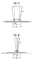
- Figure 16 shows the state of transfer of ink to the surface of a spur in the embodiment of Figure 17.
- Figure 17 shows a spur having a great width of contact as it is seen in the direction of movement of the recording medium.
- Figure 18 illustrates an embodiment of the best mode of the present invention which solves the problem of Figure 15.
- Figures 19A and 19B are a front view and a side view, respectively, of a spur.
- Figure 20 illustrates the assembled construction of the spur of Figure 19.
- Figure 21 illustrates a partial modification of the Figure 20 embodiment.
- Figure 22 illustrates a recording apparatus according to a first embodiment of the back feed system invention.
- Figures 23, 24 and 25 illustrate the setting of a recording medium according to a second embodiment of the back feed system invention.
- Figure 26 illustrates a conveyance guide according to a third embodiment of the back feed system invention.
- Referring to Figure 1 which shows the general construction of a printer using the present invention, the
reference numeral 1 designates a cartridge comprising arecording head 1a and anink tank 1b which are made integral with each other, thereference numeral 2 denotes a carriage for scanning in the subscanning direction with thecartridge 1 carried thereon, thereference numeral 3 designates the guide shaft of thecarriage 2, and the reference numeral 4 denotes the chassis of the base of the apparatus. Thereference numeral 5 designates a conveying platen roller, and the reference numerals 6 and 7 denote conveying rollers. Thereference numeral 8 designates a spur according to an embodiment of the present invention. Thespur 8 is of a shape as shown in Figure 2 and Figure 3 which is a side view corresponding to Figure 2. The reference numeral 9 denotes a conveyance guide. P designates a recording medium. Thereference numeral 10 in Figure 8 denotes ink discharged onto the recording medium. Thereference numeral 11 in Figure 10 designates a spur according to the prior art, and Figure 10 shows the transfer process of ink to the prior-art spur. - The
recording head 1a, although not shown, is provided with a plurality of liquid paths filled with well-known liquid (ink). The ink filling these liquid paths is balanced in its surface tension and external pressure on the orifice surface in its steady state. Electro-thermal converting members are disposed in said plurality of liquid paths, and at least one driving signal for providing a rapid temperature rise beyond nuclear boiling is applied to these electro-thermal converting members to thereby generate heat energy and gasify the adjacent ink, thus causing film boiling. Thereby, a bubble corresponding to the driving signal is formed in the ink, and by the growth of this bubble, the ink may be discharged from the orifice surface to the recording medium P. Also, the bubble is cooled by the ink and contracts, and ink is supplied from theink tank 1b into the liquid paths by capillary phenomenon. - By growing or contracting a bubble in the liquid paths filled with the ink as described above, the ink can be discharged from the orifice surface to form a liquid droplet. Accordingly, when the driving signal is applied in a pulse form to the electro-thermal converting members in conformity with image information, the growth and contraction of the bubble takes place in a moment, and the ink can be discharged from the orifice surface of the
recording head 1a to the recording medium P to thereby accomplish recording. - The recording operation of the printer constructed as described above will now be described. As shown in Figure 1, the recording medium P is first made to pass between the conveying
roller 5 and the rollers 6, 7, and is set until it arrives at between thespur 8 and the guide member 9. - When the recording operation is then started, the
ink cartridge 1 containing therecording head 1a therein is moved in the sub-scanning direction of thecarriage 2 and also the ink is discharged from the orifice surface of therecording head 1a onto the recording medium P in conformity with recording information, whereby recording is effected. When the recording for one line is terminated, the conveyingroller 5 is rotatively driven to convey the recording medium P by one line in the main scanning direction (the direction of arrow A). At this time, the recording medium P is conveyed while being held by thespur 8 and the guide member 9. - By the above-described operation being repeated, recording is successively effected, and the recording medium P after recording is discharged onto a stacker or the like, not shown.
- Now, the
spur 8 which directly contacts with the printing surface of the recording medium is of such structure that as shown in Figure 3, a spur (like a counter of an abacus) formed of silicone resin whoseperipheral surface 80 is of a rotational shape continuously bearing against the recording medium and which, in the front view of Figure 2, has both-side tapers symmetrically at an angle ϑ. Thus, the spur can continuously accomplish substantially point contact, and irrespective of the scanning direction of the recording medium, can prevent recorded images from being disturbed even if the spur rubs against the unfixated recording surface. - In the apparatus of the compact portable type according to the present embodiment as shown in Figure 1, as previously described, the printing portion arrives at the
spur 8 immediately after printing. The then state is shown in Figure 8. This situation is a situation in which the ink on which the spur is not settled is stationary on the recording medium P. - Figure 9 shows a state in which the recording medium P has begun to more forward in the main scanning direction from the state of Figure 8 and the
spur 8 has begun to effect relative movement at the point of contact. As shown in Figure 9, the ink adheres to the surface of the spur at the adherence energy level between the spur and the ink and therefore assumes a more protuberent shape than in the stationary state when it is stripped off by the rotation of the spur. However, the shape at that time is a flared shape with the protuberant point as the vertex. Considering the then balance of force, the peripheral surface of thespur 8 is a continuous surface and when theink 10 has been dragged up in proportion to its adhering force relative to thespur 8, the cohesive power by the surface tension of the ink which tends to reduce the flared protuberance of the ink itself to thereby reduce the surface area becomes stronger and further, the underside of theink 10 is restrained by the adhering force of the ink and the recording medium P over a large area, with a result that the ink is dragged down while sliding toward the recording medium P. Thus, the ink can be used without being transferred onto thespur 8. - If as in the prior art, the peripheral surface of the spur was a discontinuous surface, said balance of force would be momentarily destroyed and thus, the ink would be left on the spur. An extreme example of it is the example of the prior art shown in Figure 10. In this case, because of the peripheral surface being a discontinuous surface, the force with which the adhering ink is continuously dragged down would be continuous as in the present embodiment and flared protuberances would be small and created at individual points of contact and the ink would be raised substantially vertically from the printing surface, and a constriction would be created between the ink 10-b on the edge portion of the
spur 11 and the ink 10-a on the recording medium P and at last, the step area of the constricted part would become smallest and thus weakest, and the constricted part would be cut by the cohesive power provided by the surface tension of the ink 10-a and the ink 10-b. Therefore, in principle, the ink would be transferred onto thespur 11. - As can be seen from the description of Figure 10, the superiority of the effect of the present invention is clear.
- Table 1 below shows a test in which use has been made of a spur having the shape as shown in Figure 2 and in which the angle ϑ formed by the tapered portion with respect to the printing surface is 80° and the contact pressure to the surface of the recording medium is set to 20 g and samples differing in the water-repelling property of the surface have been used under environments of different humidities to effect home feed immediately after a solid black line has been printed, to thereby examine whether a spur trace has appeared.
- Table 2 below shows a similar test carried out for the shape of Figure 10 and under the same other conditions.
- Table 3 below a test in which the surface roughness of the spur has been varied relative to the test shown in Table 1.
- Table 4 below shows a test in which, relative to the test shown in Table 1, use has been made of a spur having a water-repelling property of 110° and the angle formed by the tapered portion with respect to the printing surface has been varied.
- The test of the water-repelling property has been carried out with the angle of contact with water as a standard parameter. The test of the contact pressure is shown in terms of the total pressure per spur with respect to the printing surface.


- The data shown in Tables 1 to 4 are test data including the tests on the present embodiment and the prior art carried out in the aforedescribed form of test.
- According to Table 1, it is seen that where the other parameters are fixed, if in the present embodiment, use is made of a water-repellent spur having an angle of contact of 60° or greater with respect to water, there can be obtained a spur entirely in dependent of good or bad of the fixativeness of ink attributable to the environmental humidity. Conversely, as shown in Table 2, in the spur of the conventional type, it is seen that even if use is made of a spur having a water-repelling property as high as 110° or greater, transfer will occur and the data has dependency on the environmental humidity. This is apparent from the aforedescribed principle, and the spur in the present invention may pass over unfixated ink under high humidity because the ink will not originally be transferred to the spur due to the aforedescribed principle even if the spur is rolled in the ink liquid. It is considered to be because a boundary line between good and bad by the parameter of the water repelling property has been in the vicinity of the angle of contact 30° in the setting of the present embodiment that in Table 1, NG appears at the angle of contact 30° under high humidity. In any case, it can be understood from the comparison between Table 1 and 2 that the disadvantage peculiar to the prior-art spur is solved by one or more ranks.
- In the data of the prior art shown in Table 2, a good result is obtained if use is made of a spur having an angle of contact of 110° or greater at a normal temperature of 50%RH, and this is considered to be because viscosity has increased just at a level whereat the ink has begun to be fixated and the force with which the ink adheres to the recording medium has become a little stronger in the aforedescribed principle.
- It is not because of the aforedescribed principle, but because the ink has already been dried by super-low humidity and no longer causes its transfer that the results are all OK under a low humidity of 10%RH.
- Also, Table 3 shows a test in which the surface roughness of the spur has been varied in the embodiment according to the system of the present invention, and here, for the sake of convenience, the numerical values at Rmax are used as parameters, but again, smaller surface roughness results in good sliding and reduced resistance and therefore, the force with which the ink is dragged down may be small, and this is better. The surface roughness differs in its shape from material to material although equal in numerical value, and particularly whether the surface roughness is good or bad is determined by the combination thereof with the adhering force provided by the water-repelling property.
- Table 4 shows the variations by the angle formed by the spur with respect to the printing surface, and again, an angle an approximate as possible to vertical with respect to the printing surface has led to a good result. This is because a stripping-off force is applied in a direction perpendicular to the printing surface when the ink is dragged down from the spur, and it is proved that greater ease with which the force in this direction is applied leads to a better result.
- Figures 4 and 5 showing a member whose peripheral surface is semicircular (ϑ can be regarded as 45°) and Figures 6 and 7 showing a member which can be regarded as a half of Figure 2 show further embodiments of the present invention. In both of these embodiments, the peripheral surface continuously bears against the surface of the recording medium, and so far as this is concerned, the peripheral surface need not be circular, but may be polygonal or elliptical or of an indefinite shape such as a belt-like shape, and in short, the peripheral surface can be of a continuous shape in which it is continuous without the contact thereof with the ink being discontinued near the point of contact therebetween.
- As described above, by using a paper conveying member whose peripheral surface is of such a shape that it continuously contacts with the printing surface, the effect of greatly preventing print stains such as spur traces even in the case of a compact portable type printer, or even during printing of high printing proportion on plain paper or even under a bad environment such as high humidity has become possible from a simple principle and construction.
- Reference is now had to Figures 11 to 19 to describe an invention further improved over the above-described invention.
- The above-described embodiments are ones in which the conveying property is improved and the spur trace is greatly prevented, but if the width of contact of the spur with the printing surface is increased for the conveying force and the durability up, even if said width of contact is within a range which will not permit a spur trace to appear, it has sometimes been the case with an apparatus for highly detailed graphics of 180 dpi or 300 dpi or more that because half-tone printing is often used in such apparatus, when half-tone printing of printing duty (density) of less than 50% - 100% is effected under high humidity in which the ink is difficult to fixate, image batter is much smaller than in the prior art but a slightly conspicuous black streak-like half-tone portion occurs after the spur has passed. However, in practice, such a fear has been small in an apparatus wherein the quality of printing is as low as 180 dpi or less or character printing or solid printing is main. However, it has also been experienced that if the width of contact of the spur with the recording medium is made still greater, the ink on the spur is transferred only at one point onto the spur only in the boundary line along which the spur passes from a solid black portion to the non-printing portion, and a small image stain is produced only at one point by the next contact of the spur at that point.
- This poses no problem in ordinary printing, but we have found that it should be solved when an ink record is to be obtained like a photograph. The invention which achieves this is as follows. In a paper feeding member which bears against the recording medium and rotates, design is made such that the peripheral surface thereof continuously bears against the recording medium and the width thereof in the direction of its rotational axis 0.1 mm inward of the peripheral surface is 1.0 mm or less, preferably 0.7 mm or less, whereby it is made possible to prevent the ink on the surface of the recording medium from being transferred onto solid black, as well as to prevent the ink on the boundary line between the solid black portion and the non-printing portion from being transferred onto the spur. Thereby, the compatibility of the conveyance property and printing which will produce no spur trace is made possible.
- Basically, when the spur contacts width ink, the balance of power with which the ink does or does not adhere is determined by the bonding power between the spur and the ink, the bonding power between the ink and the paper and the cohesive power by the surface tension of the ink itself, and the characteristic of this balance of power is utilized. It has been found in the present invention that by using a shape in which even the width of the spur is prescribed as in the present invention, the force with which the ink adheres to the spur when the spur moves is made so as to become always lower in any case, whereby complete non-transfer of the ink to the spur can be achieved.
- As regards the definition of the width of the rotational member of the present invention, the recording medium such as paper and this rotational member are microscopically deformed in a state in which they are in contact with each other by pressure applied thereto, and the definition becomes indefinite as to also a spur whose end surface is originally R-shaped and therefore, the width is defined by the width in the cross-setion passing the rotational axis 0.1 mm inward from the peripheral surface which bears against the recording medium.
- If based on this condition, in Figures 2 and 6, the contact is substantially the contact by the edge and therefore the width of contact is a thin line of 1 mm or less and thus, the spurs of Figures 2 and 6 are covered by the present invention and can be regarded as embodiments of the present invention.
- Now, the production of the above-described spur trace only at one point will be described briefly with reference to Figures 15, 16 and 17.
- Even in the case of a spur whose peripheral surface continuously bears against the recording medium, in the edge portion of the solid black portion, the states of the ink and the
spur 8 are as shown in Figure 15. From this point of time, the restrained area between the ink and the paper decreases extremely with the rotative conveyance and thus, the aforedescribed balance of power begins to be destroyed only at this point and the ink is transferred only to one point on the peripheral surface of the spur, as shown in Figure 16. We have found the dynamic relation that even in that case, if the width W of the spur is as narrow as 1 mm or less, the spur and the point of restraint in the widthwise direction of that portion of the spur which is adjacent to the ink are originally very narrow in the state shown in Figure 18 and therefore the ink is not transferred to the spur even if the restrained area of the recording medium in the direction of movement thereof is decreased. Conversely, if the width W exceeds 1 mm, the proportion of the restrained area of the spur in the widthwise direction thereof is great as shown in Figure 17 and therefore, the ratio between the restrained area of that portion of the recording medium which is adjacent to the ink and the restrained area of that portion of the spur which is adjacent to the ink is small, and the ink at this point is transferred at one point onto the spur, and at the next point of contact by the rotation of the spur, the ink is transferred at one point onto the recording medium. W₁ indicates the width of restraint between the surface of the recording medium and the ink. - Table 5 below shows a test in which in the case of a spur having the shape of Figure 2 and having an angle of 80° formed by the tapered portion with respect to the printing surface, the contact pressure to the surface of the paper has been set to 20 g and samples differing in the width of the end have been home-fed immediately after a solid black line has been printed under environments differing in humidity, to thereby examine whether said one point of spur trace has appeared.

- As can be seen from Table 5, the production of said one point of spur trace could also be prevented by selecting the width W of the
spur 8 of the above-described shape to 1.0 mm or less, optimally 0.7 mm or less. We have confirmed that under this condition of the width W, i.e., 0.7 mm or less, those within a preferable range under the conditions of Tables 1, 3 and 4 shown above are optimum, and have also confirmed that a good result in practical use can be obtained even if theangle 8 of Table 4 is made small (e.g. 30°). We have likewise confirmed that for a width of 0.7 mm or less, the condition of the water repelling property can be alleviated. - It is considered to be because the ink image is considerably fixated that the production of said one point of spur trace is not seen at said 25°C/10%RH.
- Preferred examples of the material having a high water-repelling property include tetrafluoroethylene resin, parfluoro-alkoxy resin, propylene hexafluoride copolymer resin, tetrafluoroethylene-ethylene copolymer resin, vinylidene fluoride resin and ethylene chloride trifluoride resin which are fluorine compound materials generally used, polymers such as high-density polyethylene, polyethylene, polypropylene, trimethyl pentene, polyacetal, nylon, polysulphone and phenol, and members having their surfaces coated with those polymers. Basically, the choice among these materials is determined with the water-repelling property, the ink-resisting property, abrasion and deformation strength being additionally taken into account.
- Figures 11 and 12 and Figures 13 and 14 show further embodiments of the present invention. Figures 11 and 12 are enlarged views of the end portion, Figure 11 showing a spur of which the corner portion is R-shaped. Figure 12 shows a spur of a shape equivalent to an R-shape including the surface of contact. Any of these figures shows the end portion of a spur whose peripheral surface continuously bears against the surface of the recording medium and whose width is 0.7 mm, and as far as this is concerned, the peripheral surface need not be circular, but may be polygonal or elliptical or of an indefinite shape such as a belt-like shape, and in short, the peripheral surface can be of a continuous shape in which it is continuous without the contact thereof with the ink being discontinued near the point of contact therebetween.
- Also, in an apparatus which is high is quality of image and in which print stain is forbidden, the spur of the present invention is best suited, and in an apparatus wherein more or less stain is approved, the spur of the invention previously described with reference to Figures 1 to 9 can be said to be best suited from the viewpoint of durability or the like. In any case, the present embodiment exhibits a considerably better level than the previously described invention.
- As described above, by using a paper conveying member whose peripheral surface is of such a shape that it continuously contacts with the printing surface and in which the width in the direction of the rotational axis 0.1 mm inward from the peripheral surface is optimally 0.7 mm or less, the effect of entirely preventing print stains such as spur traces even in the case of a compact portable type printer, or even during printing of high printing proportion on plain paper or even under a bad environment such as high humidity has become possible from a very simple principle and construction.
- Reference is now had to Figures 19 to 21 to describe an embodiment in which the conveying
member 8 is constructed simply and durability can be improved by only the replacement of parts. The feature of this embodiment is that a rotational member whose peripheral surface continuously contacts with the recording medium is constituted by a film member having a water-repelling property. - This embodiment, in which the rotational member is constituted by a film member having a water repelling property, has the advantage that the working process can be simplified and mass production of rotational members is made possible by press working of good productivity. Also, the mass production can be accomplished by minimally using the expensive water-repelling member and therefore, a lower cost can be realized.
- Figures 19A and 19B are a front view and a side view, respectively, of a spur, and Figure 20 is an illustration showing the assembled construction of the spur.
- The
spur 8, as shown in Figure 20, is comprised of aring 8a provided by press-working a water-repellent member such as tetrafluoroethylene film into a ring shape, a molded member 8d of polyethylene, polyacetal or like material comprising ashaft 8e and aguide ring 8b for thering 8a molded integrally with each other, and aguide ring 8c for thering 8a, the moldedmember 8a and theguide ring 8c being integrally mounted on both sides of thering 8a. - The
spur 8, as shown in Figures 19A and 19B, is of a shape in which the peripheral surface portion of thering 8a and the vicinity thereof protrude a little from the peripheral surface portions of theguide ring 8b and theguide ring 8c. The peripheral surface portion of thering 8a continuously bears against the recording medium P, and thespur 8 rotates freely with the discharge of the recording medium P. - According to an experiment, when polytetrafluoroethylene (PTFE) film and tetrafluoroethylenefluoroalkoxyethylene copolymer (PFA) film each having a thickness of 200 µm were used, there could be obtained a
spur 8 good in strength and conveyance property when thering 8a was brought into contact with the recording medium P with the outer diameter of thering 8a protruding by 0.25 mm from the outermost diameters of theguide ring 8b and theguide ring 8c. If the outer diameter of thering 8a protrudes by more than 0.25 mm, flexure will occur to the film and therefore, the amount of protrusion may preferably be 0.25 mm or less. The avoidance of a case where due to deformation such as cockling occurring to the recording medium P, the printing surface directly contacts with theguide ring 8b and theguide ring 8c to thereby stain the latter is the lower limit of the difference in the amount of protrusion. - When recording was carried out by the use of the
spur 8 with the environmental humidity and the angle of contact of the spur with the ink varied, there was obtained an effect similar to that described previously. - Next, the thickness of the film of the
ring 8a constituting thespur 8 is determined by the degree of image deterioration after the printing surface of the recording medium P has passed thespur 8 during the unfixation of the ink when half-tone printing is effected. - As a method of this test, the thickness of the film of the
ring 8a was determined by passing thespur 8 on the printing surface immediately after half-tone printing having an ink discharge proportion of 50%, relative to solid black printing in which the ink is full-dot-discharged by 100%, has been effected, and measuring the degree of the image deterioration caused by the blur of the ink on the printing surface by thespur 8. According to the above-described experiment, it has been found that when the thickness of the film is 300 µm or less, the quality of image can be maintained, and when the thickness of the film exceeds 300 µm, image deterioration becomes slightly conspicuous. Even in these cases, the film is not always unusable. - In the case of this embodiment, it is considered to be because the vibration of the
film 8a itself in the direction of flexure during the conveying rotation thereof is slightly occurring that the condition for obtaining a high quality of image is the thickness of 300 µm or less. In any case, again in such a construction, the above-described effect could be reliably obtained owing to the fact that in the construction of Figure 18, the width of contact so referred to herein is 300 µm or less. - The
ring 8a shown in Figure 21 is such that the vicinity of the peripheral surface portion of tetrafluoroethylene film is formed into a thinner tapered shape toward the peripheral surface portion. The method of working said film is to cause the vicinity of the peripheral surface to be composition-deformed into a tapered shape under a warm condition or a cold condition by press, and punching it into a ring shape by the next press to thereby obtain thering 8a as shown. - The vicinity of the peripheral surface portion of the
ring 8a is thus formed into a thin wall and therefore, even if the spur bears against the recording medium P, it becomes difficult for a spur trace to appear on the recording medium, and the other portion than the vicinity of the peripheral surface can be increased in thickness and therefore in strength. - While this
ring 8a is formed into one-side taper, thering 8a can also be formed into both-side taper. - Reference is now had to Figures 22 to 26 to describe an ink jet recording apparatus which can effect back feed in which the recorded surface of a recording medium is caused to pass again a recording area opposed to a recording head.
- Again in the back feed, image disturbance is caused by the conveying member which contacts with the recording surface and therefore, this embodiment is common to the aforedescribed embodiment in the solution to problems.
- The back feed is effected not immediately after recording, but after the lapse of a predetermined time and therefore, it is difficult for the above-noted problem to arise in a recording system such as the wire dot system or the heat transfer system, and this can also be said to be a problem peculiar to an ink jet recording apparatus for discharging liquid ink to thereby accomplish recording.
- This embodiment prevents the recording surface from being stained by the recording medium being conveyed in the direction opposite to the main scanning direction and rubbing against a conveyance guide or a conveying roller when so-called back feed is effected.
- The invention which will hereinafter described with reference to Figures 22 to 26 is an ink jet recording apparatus which is provided with an ink jet recording head having an ink tank for containing ink therein and discharging the ink supplied from said ink tank and in which ink droplets are discharged from said recording head to a recording medium to thereby accomplish recording, characterized in that spurs whose peripheral surface is of a rotational shape in which it continuously bears against the recording medium are disposed forwardly and rearwardly in the direction of conveyance of the recording medium. According to the present embodiment, there can be provided an ink jet recording apparatus in which there is no limitation in the direction of conveyance immediately after recording and which has a variety of recording modes.
- Another invention which solves the previously noted problem is an ink jet recording apparatus characterized in that spurs whose peripheral surface is of a rotational shape in which it continuously bears against a recording medium are disposed forwardly and rearwardly in the direction of conveyance of the recording medium, and conveyance guide means for preventing the recording medium from contacting with a conveyance guide in a state in which the recording medium has been set in the recording apparatus is provided in a conveying system wherein the conveyance guide is disposed on the recording surface side of the recording medium. According to this construction, even if irrespective of the direction in which the recording medium is conveyed and scanned, for example, back feed is effected in the ink jet recording apparatus, it becomes possible to prevent the problem of disturbing recorded images by unfixated ink.
- Still another invention is an apparatus which solves the problem that if the spur of the present invention is applied to a spacer roller for maintaining a gap between a recording head and a recording medium and is disposed in contact with the recording medium immediately after recording, the roller itself may be stained or the image may be disturbed, and can form a gap reliably. This apparatus has the advangage that even if the thickness of the recording medium fluctuates variously, any minute variation in the recording gap can be followed up and therefore the quality of recorded image can be made higher than before. This apparatus also displays an excellent effect for full color recording by superposed printing of a plurality of colored inks of which a high quality of image is required.
- Figure 22 illustrates a recording apparatus of the ink jet type.
- A
recording head cartridge 1 andcarriage guide shafts 3 are the same as those described in connection with Figure 1, while acarriage 2 is displaceable relative to theguide shafts 3 withspacer rollers 100 for maintaining the recording gap constant. In the present embodiment, the carriage hasslots guide shafts 3 and is made displaceable so that the recording gap may be constant even if the thickness of a recording medium P varies. Thespacer rollers 100 are fixed to thecarriage 2 for rotation in the scanning (sub-scanning) direction of the carriage, and are disposed in proximity to arecording head 1a. In the present embodiment, thespacer rollers 100 are provided on both sides of thehead 1a, but alternatively, aspacer roller 100 may be provided only on one side of thehead 1a. The displacing mechanism for the carriage is not limited to the present embodiment, but any conventional one may be applied. Thespacer rollers 100 are thespurs 8 in the afore-described embodiments of the present invention and therefore can maintain the recording gap highly accurately without disturbing images. In the conveyance of the recording medium after recording toward thetray 23, the effect of aroller 141 by the structure of thespur 8 is as previously described. Thereference numeral 12 designates a pair of partly cut-away paper feed rollers, thereference numerals surface side roller 131 is aspur 8, and thereference numerals surface side roller 141 is aspur 8. P denotes a recording medium. - The operation of the above-described construction will now be described. In Figure 22, the recording medium P is fed by the pair of
paper feed rollers 12 and is set as shown in Figure 22, whereafter thecartridge 1 provided with therecording head 1a effects one-line recording on the recording medium P by the movement of thecarriage 2 in the sub-scanning direction. Subsequently, the pair ofspur conveying rollers - When in the above-described apparatus, the pair of
spur conveying rollers - That is, even when back feed is effected and the spurs contact with the unfixated ink, balance is kept by the surface bonding power between the spurs and the ink, the bonding power between the ink and the recording medium and the cohesive power of the ink itself so that the force with which the ink adheres to the spurs may always be lower and therefore, non-transfer of the ink to the spurs is achieved and no image disturbance is caused.
- By the utilization of the fact that the principles of transfer and non-transfer of the ink to the spurs are independent of the scanning direction of the recording medium, spurs 8 (for example, counters of an abacus) whose peripheral surface is of a rotational shape in which it continuously bears against the recording medium are disposed forwardly and rearwardly in the direction of conveyance of the recording medium, whereby irrespective of the scanning direction of the recording medium, it becomes possible to prevent the unfixated recording surface from being rubbed to thereby cause the disturbance of recorded images.
- During one-line feeding of the recording medium in the main scanning direction, the
spacer rollers 100 disturb images and for this reason, as in the prior art, the carriage can be moved to the home position (the standby position far from the recording area). If such movement is not effected, the carriage may be retracted so that the spacer rollers may be separated from the medium. - Description will now be made of an embodiment in which, in the conveying system wherein a conveyance guide is disposed on the recording surface side of the recording medium, the recording medium does not contact with the conveyance guide in a state in which the recording medium has been set in the recording apparatus.
- Means constructed so as not to rub against the recording surface will hereinafter be described.
- Figures 23, 24 and 25 illustrate the manner in which the recording medium is set.
- As shown in Figure 23, when the recording medium P is fed, the leading end edge thereof first strikes against the
conveyance guide 15, and is conveyed along theconveyance guide 15, as shown in Figure 24. The leading end edge of the recording medium P strikes against aspur 8type paper keeper 71 and is bitten thereby, and is conveyed in the direction of arrow A as shown in Figure 25. - Then the leading end edge of the recording medium is nipped by and between a
spur 8 typepaper discharge roller 8 and a receiving roller 9. - Here, in the recording apparatus according to the present embodiment, the conveying force between the
platen roller 5 and the conveyingrollers paper discharge roller 8 and the receiving roller 9, and the recording medium conveying speed of theplaten roller 5 is lower than the conveying speed of thepaper discharge roller 8. That is, the force with which the recording medium P is conveyed and the speed at which the recording medium P is conveyed are controlled by theplaten roller 5, and thepaper discharge roller 8 is rotating at a high speed while slipping for the purpose of keeping the recording medium P tensioned. The technique of intentionally making the recording medium conveying speed different between the rollers conveying the recording medium is a known technique and therefore need not be described in detail herein. - In the present embodiment, when the recording medium P is fed and bitten by the
paper discharge roller 8, the slack in the recording medium P between theplaten roller 5 and theconveyance guide 15 is absorbed because the conveying speed of thepaper discharge roller 8 is higher than the conveying speed of theplaten roller 5, and thus there is formed a gap t between the recording medium P and the conveyance guide as shown in Figure 25. - By such gap being formed, it becomes possible to prevent the recording surface of the recording medium P being rubbed by the
conveyance guide 15 even when back feed is effected. - The spur roller
type paper keepers type paper keepers - In the above-described embodiment, contact is prevented by providing a gap t between the recording medium P and the
conveyance guide 15 as shown in Figure 25. To increase the reliability of the prevention of contact, the gap t may preferably be as wide, as possible. However, if the gap t is wide, the angle of plunge of the leading end edge of the recording medium into the spur roller type paper keeps 71 and 61 during paper feed will change and the impact of plunge will increase. - It is because the peripheral surface of the spur roller
type paper keepers type paper keepers - Also, a paper discharge roller using a spur as used while being caused to rotate and slip at a speed higher than the conveyance speed of the recording medium and therefore, the peripheral surface thereof suffers from severe abrasion.
- Figure 26 shows an embodiment suitable for kinds of machines of which a great number of durable sheets is required. In this embodiment, in addition to the construction of Figures 23 to 25, guide spurs 81 are disposed as the aforedescribed spurs of the present invention on the surface of the
conveyance guide 15 which guides the recording medium P. Thus, - 1) the recording surface of the recording medium P is supported by the guide spur 81 and does not directly contact with the guide surface of the
conveyance guide 15; - 2) the gap between the
platen roller 5 and theconveyance guide 15 can be narrowed to the necessary minimum and therefore, during paper feed, the impact of plunge of the leading end edge of the recording medium P against the spur rollertype paper keeper 71 can be minimized; and - 3) during paper feed, the recording medium P has no slack between the
platen roller 5 and theconveyance guide 15 and therefore, thepaper discharge roller 8 which is a spur need not be used while being caused to rotate and slip at a speed higher than the conveyance speed of the recording medium P. - Consequently, in the present embodiment, the frequency with which impediments such as abrasion, flaws and breakage of the
paper discharge roller 8 which is a spur and the spur rollertype paper keeper 71 occur can be decreased and therefore, high durability can be achieved. - Also, in the present embodiment, the number of the guide spurs 81 is three, but the number of the guide spurs 81 may be more or less than three.
- As regards the kinds or number of the recording heads carried on the carriage, for example, only one head may be provided correspondingly to monochromatic ink and besides, provision may be made of a plurality of heads differing in recording color or density.
- The inventions of Figures 23 to 26 are such that as previously described, in the construction wherein spurs whose peripheral surface is of a rotational shape in which it continuously bears against the recording medium are disposed forwardly and rearwardly in the direction of conveyance of the recording medium and a conveyance guide is disposed on the recording surface side of the recording medium, provision is made of conveyance guide means for preventing the recording medium from contacting with the conveyance guide in a state in which the recording medium has been set in the recording apparatus, whereby even if irrespective of the conveyance and scanning direction of the recording medium, for example, back feed is effected in the ink jet recording apparatus, it becomes possible to prevent the problem of recorded images being disturbed by unfixated ink.
- The peripheral surface of the spur need not be circular, but may be polygonal or elliptical or of an indefinite shape such as a belt-like shape, and in short, the peripheral surface need only be continuous without the contact thereof with the ink being discontinued near the point of contact.
- The present invention can more enhance the above-described operational effect by the combined effect of the fixation expediting effect of heat energy and the effect of said spur in a recording head and a recording apparatus of the bubble jet type proposed by Canon, Inc., particularly among the ink jet recording systems.
- The typical construction and principle of it may preferably be based on the basic principle disclosed, for example, U.S. Patents Nos. 4,723,129 and 4,740,796. This system is applicable to both of the so-called on-demand type and the so-called continuous type, and particularly in the case of the on-demand type, it is effective because at least one driving signal corresponding to recording information and providing a rapid temperature rise exceeding nuclear boiling is applied to an electro-thermal converting member disposed corresponding to a sheet or a liquid path in which liquid (ink) is retained, whereby heat energy is generated in the electro-thermal converting member to cause film boiling on the heat-acting surface of a recording head, with a result that a bubble corresponding at one to one to this driving signal can be formed in the liquid (ink). By the growth and contraction of this bubble, the liquid (ink) is discharged through a discharge opening to thereby form at least one droplet. If the driving signal is made into a pulse-like form, the growth and contraction of the bubble will appropriately take place on the spot and therefore, discharge of the liquid (ink) especially excellent in responsiveness can be accomplished, and this is more preferable. This driving signal in the pulse-like form may suitably be one as described in U.S. Patent No. 4,463,359 or U.S. Patent No. 4,345,262. Also, more excellent recording can be accomplished if the conditions described in U.S. Patent No. 4,313,124 which discloses an invention relating to the rate of temperature rise of said heat-acting surface are adopted.
- As the construction of the recording head, besides the construction comprising a combination of discharge ports, liquid paths and electro-thermal converting members as disclosed in each of the above-mentioned patents (straight liquid flow paths or right-angled liquid flow paths), the construction using U.S. Patents Nos. 4,558,333 and 4,459,600 which disclose a construction in which a heat-acting portion is disposed in a crooked area is also covered by the present invention. In addition, the present invention is also effective if it adopts a construction based on Japanese Laid-Open Patent Application No. 59-123670 which discloses a construction in which a slit common to a plurality of electro-thermal converting members is the discharge portion of the electro-thermal converting members or Japanese Laid-Open Patent Application No. 59-138461 which discloses a construction in which an opening for absorbing the pressure wave of heat energy corresponds to the discharge portion.
- Further, the recording head of the full line type having a length corresponding to the width of the largest recording medium on which the recording apparatus can effect recording may be of a construction in which said length is satisfied by a combination of a plurality of recording heads as disclosed in the aforementioned publications or a construction as a single recording head formed as a unit, and the present invention can display the above-described effect more effectively.
- In addition, the present invention is also effective when use is made of a recording head of the interchangeable chip type of which the electrical connection to the apparatus body and to which the supply of ink from the apparatus body becomes possible by being mounted on the apparatus body, or a recording head of the cartridge type in which a cartridge is provided integrally with the recording head itself.
- Also, the addition of recovery means for the recording head, preliminary auxiliary means, etc. provided as the construction of the recording apparatus of the present invention can more stabilize the effect of the present invention, and this is preferable. Specifically mentioning these, they include capping means for the recording head, cleaning means, pressing or suction means and preheating means comprising an electro-thermal converting member or a heating element discrete therefrom or a combination of these, and carrying out the preliminary discharge mode in which discharge discrete from that for recording is effected is also effective to accomplish stable recording.
- Further, the recording mode of the recording apparatus is not limited to the recording mode of the main color such as black, but may use a recording head constructed as a unit or a combination of a plurality of recording heads, and the present invention is also very effective for an apparatus provided with at least one of a plurality of different colors and full color by mixed colors.
- In the above-described embodiments of the present invention, the ink has been described as liquid, but the ink may be ink which solidifies at room temperature or below and softens or liquefies at room temperature, or ink which assumes the liquid phase when the recording signal used is imparted, because in the above-described ink jet, it is usual to temperature-regulate ink itself within the range of 30°C to 70°C to thereby effect temperature control so that the viscosity of the ink may be within a stable discharge range. In addition, the temperature rise by heat energy may be used as energy for the phase change of the ink from the solid phase to the liquid phase to thereby prevent such temperature rise, or ink which solidifies when left as it is may be used to prevent the evaporation of the ink, and in any case, the use of ink having the nature that it is liquefied only by heat energy, such as ink which is liquefied by the application of heat energy conforming to a recording signal and is discharged in the form of ink liquid, or ink which already begins to solidify at a point of time whereat it arrives at the recording medium, is also applicable to the present invention. In such a case, the ink may be in a form opposed to an electro-thermal converting member while being retained as liquid or solid in the recesses or through-holes of a porous sheet, as described in Japanese Laid-Open Patent Application No. 54-56847 or Japanese Laid-Open Patent Application No. 60-71260. In the present invention, what is most effective for each kind of ink described above is what executes the above-described film boiling system.
Claims (22)
recording means for recording images on a recording medium in conformity with recording information;
conveying means for conveying the recording medium to said recording means;
and discharge means for discharging said recording medium after recording,
characterized in that said discharge means has a rotational member whose peripheral surface continuously bears against said recording medium, said rotational member being constructed of a film member having a water-repelling property.
Applications Claiming Priority (8)
| Application Number | Priority Date | Filing Date | Title |
|---|---|---|---|
| JP1241048A JP3020965B2 (en) | 1989-09-18 | 1989-09-18 | Ink jet recording device |
| JP241048/89 | 1989-09-18 | ||
| JP2015290A JP2902433B2 (en) | 1990-01-30 | 1990-01-30 | Recording device |
| JP20152/90 | 1990-01-30 | ||
| JP9548290A JP2994686B2 (en) | 1990-04-11 | 1990-04-11 | Ink jet recording device |
| JP95483/90 | 1990-04-11 | ||
| JP95482/90 | 1990-04-11 | ||
| JP2095483A JPH03293175A (en) | 1990-04-11 | 1990-04-11 | Ink jet recording apparatus |
Publications (3)
| Publication Number | Publication Date |
|---|---|
| EP0419185A2 true EP0419185A2 (en) | 1991-03-27 |
| EP0419185A3 EP0419185A3 (en) | 1991-06-12 |
| EP0419185B1 EP0419185B1 (en) | 1999-03-31 |
Family
ID=27457327
Family Applications (1)
| Application Number | Title | Priority Date | Filing Date |
|---|---|---|---|
| EP90310157A Expired - Lifetime EP0419185B1 (en) | 1989-09-18 | 1990-09-17 | Conveying rotational member for an ink recording apparatus |
Country Status (7)
| Country | Link |
|---|---|
| US (1) | US5850233A (en) |
| EP (1) | EP0419185B1 (en) |
| KR (1) | KR930011860B1 (en) |
| AT (1) | ATE178272T1 (en) |
| AU (1) | AU651561B2 (en) |
| CA (1) | CA2025547C (en) |
| DE (1) | DE69033028T2 (en) |
Cited By (3)
| Publication number | Priority date | Publication date | Assignee | Title |
|---|---|---|---|---|
| EP0511424A1 (en) * | 1991-04-30 | 1992-11-04 | Hirakawa Kogyosha Co., Ltd. | Sheetlike article conveying roller assembly |
| EP0580399A2 (en) * | 1992-07-20 | 1994-01-26 | Kabushiki Kaisha TEC | Ink jet printer |
| DE4330798A1 (en) * | 1992-09-10 | 1994-03-17 | Seiko Epson Corp | printer |
Families Citing this family (14)
| Publication number | Priority date | Publication date | Assignee | Title |
|---|---|---|---|---|
| US20030109201A1 (en) * | 2001-12-07 | 2003-06-12 | Ossio Veronica Sara | Procedure for manufacturing artistic and utilitarian objects from stone |
| US6741342B2 (en) | 2002-04-10 | 2004-05-25 | Hewlett-Packard Development Company, L.P. | Using a laser beam to indicate roller wear |
| US6677749B2 (en) | 2002-04-10 | 2004-01-13 | Hewlett-Packard Development Company, L.P. | Using variable inductance to indicate roller wear |
| NL1027002C2 (en) * | 2004-09-09 | 2006-03-13 | Oce Tech Bv | Method for printing a substrate with an inkjet printer, and an inkjet printer suitable for applying this method. |
| JP4533274B2 (en) * | 2005-08-11 | 2010-09-01 | キヤノン株式会社 | Liquid coating apparatus and inkjet recording apparatus |
| JP4480166B2 (en) * | 2005-08-11 | 2010-06-16 | キヤノン株式会社 | Liquid coating apparatus and inkjet recording apparatus |
| JP4533275B2 (en) * | 2005-08-11 | 2010-09-01 | キヤノン株式会社 | Liquid coating apparatus and inkjet recording apparatus |
| JP4669347B2 (en) | 2005-08-15 | 2011-04-13 | キヤノン株式会社 | Liquid coating apparatus and inkjet recording apparatus |
| US7828287B2 (en) * | 2009-01-29 | 2010-11-09 | Dell Products L.P. | Printer star wheel |
| US8087773B2 (en) * | 2009-05-26 | 2012-01-03 | Xerox Corporation | Ink jet printing depth of focus control apparatus |
| JP6079306B2 (en) | 2013-02-28 | 2017-02-15 | ブラザー工業株式会社 | Recording device |
| JP5935719B2 (en) | 2013-02-28 | 2016-06-15 | ブラザー工業株式会社 | Recording apparatus and manufacturing method thereof |
| EP2933112B1 (en) * | 2014-04-16 | 2016-11-02 | OCE-Technologies B.V. | Printer for forming an inkjet image |
| JP6662115B2 (en) | 2016-03-09 | 2020-03-11 | セイコーエプソン株式会社 | Roller and printing apparatus including the roller |
Citations (4)
| Publication number | Priority date | Publication date | Assignee | Title |
|---|---|---|---|---|
| US3042179A (en) * | 1959-10-19 | 1962-07-03 | Mouroe Calculating Machine Com | Sheet fefding mechanism |
| US4463359A (en) * | 1979-04-02 | 1984-07-31 | Canon Kabushiki Kaisha | Droplet generating method and apparatus thereof |
| JPS59214677A (en) * | 1983-05-20 | 1984-12-04 | Canon Inc | Paper feeder mechanism |
| JPS6397649A (en) * | 1986-10-15 | 1988-04-28 | Asahi Chem Ind Co Ltd | Rubber roll for business machine |
Family Cites Families (22)
| Publication number | Priority date | Publication date | Assignee | Title |
|---|---|---|---|---|
| US3602140A (en) * | 1970-02-09 | 1971-08-31 | Ralph E Sudduth | Rotary antismut device having radially adjustable sheet-supporting wheels |
| US3791644A (en) * | 1972-12-14 | 1974-02-12 | H Demoore | Sheet handling apparatus |
| FR2387783A1 (en) * | 1977-04-19 | 1978-11-17 | Siemens Ag | PRESSURE ROLLER FOR INK WRITING DEVICES |
| DE2734041C2 (en) * | 1977-07-28 | 1979-05-31 | Olympia Werke Ag, 2940 Wilhelmshaven | Paper guide for an ink jet printer |
| US4165029A (en) * | 1977-09-28 | 1979-08-21 | Silonics, Inc. | Paper advance mechanism for an ink jet printer |
| CA1127227A (en) * | 1977-10-03 | 1982-07-06 | Ichiro Endo | Liquid jet recording process and apparatus therefor |
| JPS5936879B2 (en) * | 1977-10-14 | 1984-09-06 | キヤノン株式会社 | Thermal transfer recording medium |
| US4330787A (en) * | 1978-10-31 | 1982-05-18 | Canon Kabushiki Kaisha | Liquid jet recording device |
| US4345262A (en) * | 1979-02-19 | 1982-08-17 | Canon Kabushiki Kaisha | Ink jet recording method |
| DE2919727A1 (en) * | 1979-05-16 | 1980-11-20 | Olympia Werke Ag | DEVICE FOR CLOSING THE NOZZLE AREA ON AN INK WRITING HEAD |
| US4313124A (en) * | 1979-05-18 | 1982-01-26 | Canon Kabushiki Kaisha | Liquid jet recording process and liquid jet recording head |
| US4558333A (en) * | 1981-07-09 | 1985-12-10 | Canon Kabushiki Kaisha | Liquid jet recording head |
| JPS59123670A (en) * | 1982-12-28 | 1984-07-17 | Canon Inc | Ink jet head |
| JPS59138461A (en) * | 1983-01-28 | 1984-08-08 | Canon Inc | Liquid jet recording apparatus |
| JPS59188467A (en) * | 1983-04-12 | 1984-10-25 | Seiko Epson Corp | Paper-pressing mechanism for ink jet printer |
| JPS6071260A (en) * | 1983-09-28 | 1985-04-23 | Erumu:Kk | Recorder |
| NL8403725A (en) * | 1984-12-07 | 1986-07-01 | Philips Nv | Device for transporting a flexible strip. |
| US4967661A (en) * | 1987-06-05 | 1990-11-06 | Duarte Procuts, Inc. | Sheet transfer mechanism for printing press |
| US4860026A (en) * | 1987-06-25 | 1989-08-22 | Canon Kabushiki Kaisha | Halftone image recording method using recording data having a plurality of concentrations for one color |
| US4977828A (en) * | 1989-08-07 | 1990-12-18 | Printing Research, Inc. | Transfer roller device for printing presses |
| US5163674A (en) * | 1991-09-27 | 1992-11-17 | Xerox Corporation | Drive means for a recording medium having liquid images thereon |
| US5363129A (en) * | 1991-10-31 | 1994-11-08 | Hewlett-Packard Company | Printing media feed and retaining apparatus for a thermal ink jet printer/plotter |
-
1990
- 1990-09-17 EP EP90310157A patent/EP0419185B1/en not_active Expired - Lifetime
- 1990-09-17 CA CA002025547A patent/CA2025547C/en not_active Expired - Lifetime
- 1990-09-17 DE DE69033028T patent/DE69033028T2/en not_active Expired - Fee Related
- 1990-09-17 AT AT90310157T patent/ATE178272T1/en not_active IP Right Cessation
- 1990-09-18 AU AU62636/90A patent/AU651561B2/en not_active Ceased
- 1990-09-18 KR KR1019900014760A patent/KR930011860B1/en not_active IP Right Cessation
-
1995
- 1995-06-07 US US08/488,461 patent/US5850233A/en not_active Expired - Fee Related
Patent Citations (4)
| Publication number | Priority date | Publication date | Assignee | Title |
|---|---|---|---|---|
| US3042179A (en) * | 1959-10-19 | 1962-07-03 | Mouroe Calculating Machine Com | Sheet fefding mechanism |
| US4463359A (en) * | 1979-04-02 | 1984-07-31 | Canon Kabushiki Kaisha | Droplet generating method and apparatus thereof |
| JPS59214677A (en) * | 1983-05-20 | 1984-12-04 | Canon Inc | Paper feeder mechanism |
| JPS6397649A (en) * | 1986-10-15 | 1988-04-28 | Asahi Chem Ind Co Ltd | Rubber roll for business machine |
Non-Patent Citations (3)
| Title |
|---|
| Book no. , 1970, 'LEHRBUCH DER EXPERIMENTALPHYSIK, BAND 1', BERGMANN-SCH{FER W. DE GRUYTER & CO. , BERLIN * |
| PATENT ABSTRACTS OF JAPAN, vol. 12, no. 338 (C-527)[3185], 12th September 1988; & JP-A-63 97 649 (AKIYAMA) 28-04-1988 * |
| PATENT ABSTRACTS OF JAPAN, vol. 9, no. 87 (M-372)[1810], 17th April 1985; & JP-A-59 214 677 (HIRAMATSU) 04-12-1984 * |
Cited By (4)
| Publication number | Priority date | Publication date | Assignee | Title |
|---|---|---|---|---|
| EP0511424A1 (en) * | 1991-04-30 | 1992-11-04 | Hirakawa Kogyosha Co., Ltd. | Sheetlike article conveying roller assembly |
| EP0580399A2 (en) * | 1992-07-20 | 1994-01-26 | Kabushiki Kaisha TEC | Ink jet printer |
| EP0580399A3 (en) * | 1992-07-20 | 1995-01-25 | Tokyo Electric Co Ltd | Ink jet printer. |
| DE4330798A1 (en) * | 1992-09-10 | 1994-03-17 | Seiko Epson Corp | printer |
Also Published As
| Publication number | Publication date |
|---|---|
| DE69033028D1 (en) | 1999-05-06 |
| KR930011860B1 (en) | 1993-12-21 |
| AU651561B2 (en) | 1994-07-28 |
| EP0419185B1 (en) | 1999-03-31 |
| US5850233A (en) | 1998-12-15 |
| AU6263690A (en) | 1991-03-21 |
| DE69033028T2 (en) | 1999-09-16 |
| EP0419185A3 (en) | 1991-06-12 |
| KR910006021A (en) | 1991-04-27 |
| ATE178272T1 (en) | 1999-04-15 |
| CA2025547C (en) | 1995-07-18 |
| CA2025547A1 (en) | 1991-03-19 |
Similar Documents
| Publication | Publication Date | Title |
|---|---|---|
| EP0419185B1 (en) | Conveying rotational member for an ink recording apparatus | |
| US8662635B2 (en) | Fluid ejection device, flushing method, and flushing program | |
| JPH06134998A (en) | Ink jet recorder | |
| JPH07329388A (en) | Recording device and information processing system | |
| JP2001180057A (en) | Recording apparatus | |
| US6536864B2 (en) | Image forming apparatus | |
| JPH11300944A (en) | Ink jet recording apparatus | |
| JPH07125228A (en) | Ink jet recording apparatus and cleaning method | |
| JP2006347039A (en) | Inkjet printer and apparatus for controlling it | |
| JP2994686B2 (en) | Ink jet recording device | |
| JP2847445B2 (en) | Recording device | |
| JP2001179953A (en) | Ink jet recorder | |
| JPH0482764A (en) | Recording device | |
| US6851801B2 (en) | Recording material conveying device and ink jet recording apparatus using such device | |
| JP3026683B2 (en) | Recording device | |
| US6322263B1 (en) | Printing apparatus and printing control method | |
| JPH0880647A (en) | Recording device | |
| JPH10309802A (en) | Mount structure of cartridge unit, recording apparatus including the mount structure, and information-processing system | |
| JPH06270415A (en) | Ink jet recording apparatus | |
| JPH06143596A (en) | Ink jet recorder | |
| JP2002036659A (en) | Recorder | |
| JPH04288267A (en) | Recording apparatus | |
| JPS6330275A (en) | Recording apparatus | |
| JP2004066678A (en) | Inkjet recording method and inkjet recording apparatus | |
| JP2000309135A (en) | Recording device and recording control method |
Legal Events
| Date | Code | Title | Description |
|---|---|---|---|
| PUAI | Public reference made under article 153(3) epc to a published international application that has entered the european phase |
Free format text: ORIGINAL CODE: 0009012 |
|
| 17P | Request for examination filed |
Effective date: 19901231 |
|
| AK | Designated contracting states |
Kind code of ref document: A2 Designated state(s): AT BE CH DE DK ES FR GB GR IT LI LU NL SE |
|
| PUAL | Search report despatched |
Free format text: ORIGINAL CODE: 0009013 |
|
| AK | Designated contracting states |
Kind code of ref document: A3 Designated state(s): AT BE CH DE DK ES FR GB GR IT LI LU NL SE |
|
| 17Q | First examination report despatched |
Effective date: 19930210 |
|
| GRAG | Despatch of communication of intention to grant |
Free format text: ORIGINAL CODE: EPIDOS AGRA |
|
| GRAG | Despatch of communication of intention to grant |
Free format text: ORIGINAL CODE: EPIDOS AGRA |
|
| GRAG | Despatch of communication of intention to grant |
Free format text: ORIGINAL CODE: EPIDOS AGRA |
|
| GRAH | Despatch of communication of intention to grant a patent |
Free format text: ORIGINAL CODE: EPIDOS IGRA |
|
| GRAH | Despatch of communication of intention to grant a patent |
Free format text: ORIGINAL CODE: EPIDOS IGRA |
|
| GRAA | (expected) grant |
Free format text: ORIGINAL CODE: 0009210 |
|
| AK | Designated contracting states |
Kind code of ref document: B1 Designated state(s): AT BE CH DE DK ES FR GB GR IT LI LU NL SE |
|
| PG25 | Lapsed in a contracting state [announced via postgrant information from national office to epo] |
Ref country code: BE Free format text: LAPSE BECAUSE OF FAILURE TO SUBMIT A TRANSLATION OF THE DESCRIPTION OR TO PAY THE FEE WITHIN THE PRESCRIBED TIME-LIMIT Effective date: 19990331 Ref country code: AT Free format text: LAPSE BECAUSE OF FAILURE TO SUBMIT A TRANSLATION OF THE DESCRIPTION OR TO PAY THE FEE WITHIN THE PRESCRIBED TIME-LIMIT Effective date: 19990331 Ref country code: SE Free format text: THE PATENT HAS BEEN ANNULLED BY A DECISION OF A NATIONAL AUTHORITY Effective date: 19990331 Ref country code: LI Free format text: LAPSE BECAUSE OF FAILURE TO SUBMIT A TRANSLATION OF THE DESCRIPTION OR TO PAY THE FEE WITHIN THE PRESCRIBED TIME-LIMIT Effective date: 19990331 Ref country code: CH Free format text: LAPSE BECAUSE OF FAILURE TO SUBMIT A TRANSLATION OF THE DESCRIPTION OR TO PAY THE FEE WITHIN THE PRESCRIBED TIME-LIMIT Effective date: 19990331 Ref country code: ES Free format text: THE PATENT HAS BEEN ANNULLED BY A DECISION OF A NATIONAL AUTHORITY Effective date: 19990331 Ref country code: GR Free format text: LAPSE BECAUSE OF NON-PAYMENT OF DUE FEES Effective date: 19990331 |
|
| REF | Corresponds to: |
Ref document number: 178272 Country of ref document: AT Date of ref document: 19990415 Kind code of ref document: T |
|
| REG | Reference to a national code |
Ref country code: CH Ref legal event code: EP |
|
| REF | Corresponds to: |
Ref document number: 69033028 Country of ref document: DE Date of ref document: 19990506 |
|
| PG25 | Lapsed in a contracting state [announced via postgrant information from national office to epo] |
Ref country code: DK Free format text: LAPSE BECAUSE OF FAILURE TO SUBMIT A TRANSLATION OF THE DESCRIPTION OR TO PAY THE FEE WITHIN THE PRESCRIBED TIME-LIMIT Effective date: 19990630 |
|
| ET | Fr: translation filed | ||
| PG25 | Lapsed in a contracting state [announced via postgrant information from national office to epo] |
Ref country code: LU Free format text: LAPSE BECAUSE OF NON-PAYMENT OF DUE FEES Effective date: 19990917 |
|
| REG | Reference to a national code |
Ref country code: CH Ref legal event code: PL |
|
| PLBE | No opposition filed within time limit |
Free format text: ORIGINAL CODE: 0009261 |
|
| STAA | Information on the status of an ep patent application or granted ep patent |
Free format text: STATUS: NO OPPOSITION FILED WITHIN TIME LIMIT |
|
| 26N | No opposition filed | ||
| REG | Reference to a national code |
Ref country code: GB Ref legal event code: IF02 |
|
| PGFP | Annual fee paid to national office [announced via postgrant information from national office to epo] |
Ref country code: IT Payment date: 20080920 Year of fee payment: 19 Ref country code: NL Payment date: 20080915 Year of fee payment: 19 |
|
| PGFP | Annual fee paid to national office [announced via postgrant information from national office to epo] |
Ref country code: GB Payment date: 20080911 Year of fee payment: 19 |
|
| PGFP | Annual fee paid to national office [announced via postgrant information from national office to epo] |
Ref country code: DE Payment date: 20080930 Year of fee payment: 19 |
|
| PGFP | Annual fee paid to national office [announced via postgrant information from national office to epo] |
Ref country code: FR Payment date: 20080923 Year of fee payment: 19 |
|
| REG | Reference to a national code |
Ref country code: NL Ref legal event code: V1 Effective date: 20100401 |
|
| GBPC | Gb: european patent ceased through non-payment of renewal fee |
Effective date: 20090917 |
|
| REG | Reference to a national code |
Ref country code: FR Ref legal event code: ST Effective date: 20100531 |
|
| PG25 | Lapsed in a contracting state [announced via postgrant information from national office to epo] |
Ref country code: NL Free format text: LAPSE BECAUSE OF NON-PAYMENT OF DUE FEES Effective date: 20100401 Ref country code: DE Free format text: LAPSE BECAUSE OF NON-PAYMENT OF DUE FEES Effective date: 20100401 Ref country code: FR Free format text: LAPSE BECAUSE OF NON-PAYMENT OF DUE FEES Effective date: 20090930 |
|
| PG25 | Lapsed in a contracting state [announced via postgrant information from national office to epo] |
Ref country code: GB Free format text: LAPSE BECAUSE OF NON-PAYMENT OF DUE FEES Effective date: 20090917 |
|
| PG25 | Lapsed in a contracting state [announced via postgrant information from national office to epo] |
Ref country code: IT Free format text: LAPSE BECAUSE OF NON-PAYMENT OF DUE FEES Effective date: 20090917 |