EP0419096B1 - Silicon grain refinement of zirconium - Google Patents
Silicon grain refinement of zirconium Download PDFInfo
- Publication number
- EP0419096B1 EP0419096B1 EP90309777A EP90309777A EP0419096B1 EP 0419096 B1 EP0419096 B1 EP 0419096B1 EP 90309777 A EP90309777 A EP 90309777A EP 90309777 A EP90309777 A EP 90309777A EP 0419096 B1 EP0419096 B1 EP 0419096B1
- Authority
- EP
- European Patent Office
- Prior art keywords
- zirconium
- tube
- ppm
- alloy
- cladding
- Prior art date
- Legal status (The legal status is an assumption and is not a legal conclusion. Google has not performed a legal analysis and makes no representation as to the accuracy of the status listed.)
- Expired - Lifetime
Links
- QCWXUUIWCKQGHC-UHFFFAOYSA-N Zirconium Chemical compound [Zr] QCWXUUIWCKQGHC-UHFFFAOYSA-N 0.000 title claims description 51
- 229910052726 zirconium Inorganic materials 0.000 title claims description 49
- 229910052710 silicon Inorganic materials 0.000 title claims description 29
- 239000010703 silicon Substances 0.000 title claims description 29
- XUIMIQQOPSSXEZ-UHFFFAOYSA-N Silicon Chemical compound [Si] XUIMIQQOPSSXEZ-UHFFFAOYSA-N 0.000 title description 27
- 238000005253 cladding Methods 0.000 claims description 21
- 229910001093 Zr alloy Inorganic materials 0.000 claims description 20
- 238000004519 manufacturing process Methods 0.000 claims description 10
- 238000000034 method Methods 0.000 claims description 8
- 239000000463 material Substances 0.000 claims description 7
- 239000003758 nuclear fuel Substances 0.000 claims description 5
- XLYOFNOQVPJJNP-UHFFFAOYSA-N water Substances O XLYOFNOQVPJJNP-UHFFFAOYSA-N 0.000 claims description 5
- 238000001125 extrusion Methods 0.000 claims description 3
- 238000010791 quenching Methods 0.000 claims description 3
- 230000000171 quenching effect Effects 0.000 claims description 3
- 238000010438 heat treatment Methods 0.000 claims description 2
- 229910045601 alloy Inorganic materials 0.000 claims 3
- 239000000956 alloy Substances 0.000 claims 3
- 230000001747 exhibiting effect Effects 0.000 claims 1
- 238000005482 strain hardening Methods 0.000 claims 1
- XEEYBQQBJWHFJM-UHFFFAOYSA-N iron Substances [Fe] XEEYBQQBJWHFJM-UHFFFAOYSA-N 0.000 description 39
- 229910052742 iron Inorganic materials 0.000 description 17
- 239000000446 fuel Substances 0.000 description 8
- 239000012535 impurity Substances 0.000 description 7
- 238000007792 addition Methods 0.000 description 6
- 230000004888 barrier function Effects 0.000 description 6
- 238000009826 distribution Methods 0.000 description 6
- 238000000137 annealing Methods 0.000 description 5
- 238000005336 cracking Methods 0.000 description 5
- 238000002474 experimental method Methods 0.000 description 5
- 230000003993 interaction Effects 0.000 description 5
- 230000015572 biosynthetic process Effects 0.000 description 4
- 238000002844 melting Methods 0.000 description 4
- 230000008018 melting Effects 0.000 description 4
- 239000008188 pellet Substances 0.000 description 4
- 230000008901 benefit Effects 0.000 description 3
- 238000005260 corrosion Methods 0.000 description 3
- 230000000694 effects Effects 0.000 description 3
- 239000000047 product Substances 0.000 description 3
- 238000001953 recrystallisation Methods 0.000 description 3
- ZCYVEMRRCGMTRW-UHFFFAOYSA-N 7553-56-2 Chemical compound [I] ZCYVEMRRCGMTRW-UHFFFAOYSA-N 0.000 description 2
- 229910052782 aluminium Inorganic materials 0.000 description 2
- XAGFODPZIPBFFR-UHFFFAOYSA-N aluminium Chemical compound [Al] XAGFODPZIPBFFR-UHFFFAOYSA-N 0.000 description 2
- 230000007797 corrosion Effects 0.000 description 2
- 230000002939 deleterious effect Effects 0.000 description 2
- 239000011630 iodine Substances 0.000 description 2
- 229910052740 iodine Inorganic materials 0.000 description 2
- 229910052751 metal Inorganic materials 0.000 description 2
- 239000002184 metal Substances 0.000 description 2
- 239000002244 precipitate Substances 0.000 description 2
- 230000009467 reduction Effects 0.000 description 2
- 238000007670 refining Methods 0.000 description 2
- 239000010936 titanium Substances 0.000 description 2
- 238000011282 treatment Methods 0.000 description 2
- WEAMLHXSIBDPGN-UHFFFAOYSA-N (4-hydroxy-3-methylphenyl) thiocyanate Chemical compound CC1=CC(SC#N)=CC=C1O WEAMLHXSIBDPGN-UHFFFAOYSA-N 0.000 description 1
- 229910000519 Ferrosilicon Inorganic materials 0.000 description 1
- RTAQQCXQSZGOHL-UHFFFAOYSA-N Titanium Chemical compound [Ti] RTAQQCXQSZGOHL-UHFFFAOYSA-N 0.000 description 1
- 239000004411 aluminium Substances 0.000 description 1
- QVGXLLKOCUKJST-UHFFFAOYSA-N atomic oxygen Chemical compound [O] QVGXLLKOCUKJST-UHFFFAOYSA-N 0.000 description 1
- 238000009835 boiling Methods 0.000 description 1
- 238000006243 chemical reaction Methods 0.000 description 1
- 238000001816 cooling Methods 0.000 description 1
- RKTYLMNFRDHKIL-UHFFFAOYSA-N copper;5,10,15,20-tetraphenylporphyrin-22,24-diide Chemical compound [Cu+2].C1=CC(C(=C2C=CC([N-]2)=C(C=2C=CC=CC=2)C=2C=CC(N=2)=C(C=2C=CC=CC=2)C2=CC=C3[N-]2)C=2C=CC=CC=2)=NC1=C3C1=CC=CC=C1 RKTYLMNFRDHKIL-UHFFFAOYSA-N 0.000 description 1
- 239000013078 crystal Substances 0.000 description 1
- 230000004992 fission Effects 0.000 description 1
- 238000005242 forging Methods 0.000 description 1
- 230000006872 improvement Effects 0.000 description 1
- 230000006698 induction Effects 0.000 description 1
- XWHPIFXRKKHEKR-UHFFFAOYSA-N iron silicon Chemical compound [Si].[Fe] XWHPIFXRKKHEKR-UHFFFAOYSA-N 0.000 description 1
- 238000009533 lab test Methods 0.000 description 1
- 238000003754 machining Methods 0.000 description 1
- 238000005259 measurement Methods 0.000 description 1
- 229910001092 metal group alloy Inorganic materials 0.000 description 1
- 150000002739 metals Chemical class 0.000 description 1
- 239000000203 mixture Substances 0.000 description 1
- 239000001301 oxygen Substances 0.000 description 1
- 229910052760 oxygen Inorganic materials 0.000 description 1
- OOAWCECZEHPMBX-UHFFFAOYSA-N oxygen(2-);uranium(4+) Chemical compound [O-2].[O-2].[U+4] OOAWCECZEHPMBX-UHFFFAOYSA-N 0.000 description 1
- 239000002245 particle Substances 0.000 description 1
- 230000003389 potentiating effect Effects 0.000 description 1
- 238000001556 precipitation Methods 0.000 description 1
- 230000002285 radioactive effect Effects 0.000 description 1
- 239000000126 substance Substances 0.000 description 1
- 239000000758 substrate Substances 0.000 description 1
- 229910052719 titanium Inorganic materials 0.000 description 1
- FCTBKIHDJGHPPO-UHFFFAOYSA-N uranium dioxide Inorganic materials O=[U]=O FCTBKIHDJGHPPO-UHFFFAOYSA-N 0.000 description 1
- -1 zirconium metals Chemical class 0.000 description 1
- 229910021355 zirconium silicide Inorganic materials 0.000 description 1
Images

Classifications
-
- C—CHEMISTRY; METALLURGY
- C22—METALLURGY; FERROUS OR NON-FERROUS ALLOYS; TREATMENT OF ALLOYS OR NON-FERROUS METALS
- C22C—ALLOYS
- C22C16/00—Alloys based on zirconium
Definitions
- the present invention relates to the control of grain structure in unalloyed zirconium metal and, more particularly, to the control of grain structure in zirconium metals containing less than 300 parts per million Fe.
- Zirconium tubing containing an outer layer of zirconium metal alloy and an inner layer of unalloyed zirconium metal is used extensively in nuclear power reactors and, in particular, in boiling water reactors.
- the tubing is used to form a cladding to contain and support nuclear fuel pellets, usually made of uranium dioxide.
- the purpose of the pure or unalloyed zirconium liner is to reduce or prevent local chemical or mechanical interaction, or both, between the fuel pellets during the operation of the reactor and the more susceptible and more reactive outer zirconium alloy sheath. Such interactions between the fuel pellets and the cladding material is believed to be responsible for what is termed 'iodine assisted stress corrosion cracking' of the outer zirconium alloy (Zircaloy) sheath.
- the resultant cracking of the sheath is deleterious to the safety of the reactor operation and to the lifetime of the fuel as it permits radioactive gaseous products of the fission reactions to diffuse therethrough and escape into the reactor vessel as well as permitting water or steam to contact the fuel elements directly.
- GB-A-2,172,737 discloses the use of zirconium of moderate purity, less than 5000 ppm total impurities with an iron content of from 250 to 1000 ppm. Further improvement in this relatively inert unreactive liner which provides the ductility required to prevent the pellet-cladding interactions described is achieved by the use of substantially pure zirconium.
- US-A-4 390 497 discloses the use of a cladding of such substantially pure zirconium, being defined as containing less than 5000 ppm impurities, with an iron content of 1500 ppm or less and a silicon content of 120 ppm or less.
- JP-A-62 298 791 teaches the use of a liner of pure zirconium where the total amount of aluminium and silicon is controlled to 70 ppm or less in order to improve the resistance to stress-corrosion cracking.
- the metallurgical grain size of the zirconium in the liner tends to increase.
- impurities such as iron when present in amounts above its solubility limit in zirconium tend to pin grain boundaries in place during the thermal processing required in the manufacture of the liner if the iron is present as a finely dispersed intermetallic second phase.
- secondary grain growth occurs which contributes to the formation of a non-uniform bi-modal grain size distribution where many smaller grains coexist with many larger grains. This bi-modal or duplex distribution creates problems during the subsequent fabrication processing for making barrier tube shells into finished tubing.
- a zirconium alloy tube mated to an unalloyed zirconium tube are tube reduced in a Pilger mill which reduces the size of the tube to the eventual size of the combination for its cladding function.
- the purity of the zirconium liner has reduced the pinning function of some impurities and a bi-modal grain distribution has formed, local microcracking begins to occur at the grain boundaries between the clusters of large and small grains. It is believed that the local deformation inhomogeneities present between clusters or aggregates of large grains and aggregates or clusters of small grains, causes the zirconium to respond differently to deformation induced straining. It appears that the stresses created in the tube reducing operation can exceed the cohesive strength of the grain boundaries. The resultant microcracks, if numerous or deep enough, will significantly reduce the liner's ability to prevent the local pellet-cladding interactions previously described.
- Uniform small diameter grain sizes are achieved in substantially pure zirconium containing generally less than 300 parts per million of Fe, by the addition of small amounts of silicon to the zirconium compacts during electrode formation for subsequent vacuum arc melting to produce zirconium ingots. Silicon is added in amounts of from 40 parts per million to 120 parts per million and most preferably in amounts of 60 to 90 parts per million to achieve the objects and advantages described herein.
- a method of making a two component cladding element using the substantially pure zirconium of the invention is claimed in claims 3 to 7.
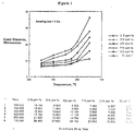
- Figure 1 is a graph of average grain diameter vs. annealing temperature at constant time from a range of iron and silicon in unalloyed zirconium.
- Figure 2 is a graph of average grain diameter for different concentrations of Silicon in zirconium for unquenched billets and beta quenched billets.
- Silicon is known to be a potent grain refiner for a variety of metals including iron, titanium and aluminum as well as zirconium.
- the atomistic nature of grain refinement in zirconium is believed to occur because silicon combines with zirconium to form a tetragonal crystal structure, Zr3Si.
- Precipitation of extremely fine (less than 10-6m) zirconium silicide (Zr3Si.) particles occurs during cooling from the beta or body center cubic phase of zirconium. These fine Zr3Si precipitates serve to retard grain boundary movement. By doing this, grain growth is retarded and secondary recrystallization is prevented.
- the grains follow the classical log-normal size vs.
- a barrier tube shell for nuclear reactor fuel cladding there is an external layer of zirconium alloy and an internal or barrier layer of unalloyed zirconium.
- an ingot of zirconium alloy typically Zircaloy 2
- rotary forged machined into billets and beta quenched into water from about 1050-1150°C.
- An ingot of unalloyed zirconium is produced by multiple vacuum arc melting and is press forged and rotary forged into logs. The logs are machined into billets with an internal hole bored down the central axis, the length of the billet.
- the zirconium billets are extruded in the alpha temperature range into tubes.
- the extruded zirconium tube is cut to length and machined to fit a central hole bored through the Zircaloy billet.
- the liner tube and Zircaloy billet are cleaned, assembled and welded together.
- the assembled billet and liner tube are heated into the alpha range (600°C to 700°C) and coextruded into a barrier tubeshell. During coextrusion the barrier layer becomes intimately bonded to the Zircaloy substrate.
- the coextruded tubeshells are then annealed in the alpha range and can then be subjected to a series of cold reduction steps and alpha annealing treatments, typically using a Pilger mill.
- the final size fuel cladding is achieved,
- Uniform fine grain size is achieved by multiple cold reductions followed by recrystallization anneals. Annealing is limited to a temperature of less than 700°c for 2 hrs. and preferably in the range of from 620°C to 675°c to less than 650°c for 1 hr.
- the grain size of coextruded zirconium liner thus treated has an ASTM grain size of 9.5 to 11.
- Advantages of the current invention include achieving a uniform fine grain size while controlling overall level of impurities (especially iron) to a much lower level than previously employed or than required by some proposed practices described in German Patent Application DE 3609074A1 filed March 18, 1986 by Daniel Charquet and Marc Perez. Additionally, no further special heat treatments or quenching operations are required to ensure the effectiveness of the silicon addition. Because no additional process steps are required, the manufacturing costs are not increased over conventional practice.
- the first series of experiments consisted of arc melting 250 grams buttons of pure zirconium with intentional additions of iron and silicon to compare the effectiveness of silicon vs. iron.
- the iron levels varied from 215 ppm to 1240 ppm.
- Silicon was added at the 90 ppm level to a low iron (245 ppm Fe) button.
- the buttons were remelted into small rectangular ingots which were then hot rolled to an intermediate thickness of 5.08 mm (0.2").
- the hotband thus produced was vacuum annealed at 625°C for 2 hours.
- the annealed hotband was cold rolled to 2.54 mm (0.1") thick and again vacuum annealed at 625°C for 2 hours.
- the strip was further cold rolled to 1.016 mm (0.040") thick. Vacuum or air final anneals were performed over the ranges of 500°C to 700°C and 1.0 hr to 10 hrs. All specimens were metallographically prepared and photomicrographs were obtained. From the photomicrographs, a line intercept counting technique was used to determine average grain diameter in micrometers.
- Figure 1 displays a plot of average grain diameter vs. annealing temperature (annealing time 2 hrs.) for the range of iron and silicon compositions mentioned above. One can see that in the non-quenched condition, the sample containing 92 ppm Si and 245 ppm Fe has a smaller grain size than does the sample with the highest iron level of 1240 ppm.
- buttons were melted to give a range of silicon from 12 ppm to 94 ppm.
- the buttons were drop cast into rectangular ingots, hot rolled, annealed, cold rolled and final annealed at 625°C for 0.1-10 hrs., as in the first experiment.
- the average grain diameter for a 625°C - 10 hr. final anneal was obtained and is shown in Figure 2 plotted against the silicon content.
- the hotband was split into two equal quantities and one half was beta quenched while the other half was not.
- the optimum level of silicon is greater than 40 ppm and less than 100 ppm with most grain refinement occurring by about 60 ppm.
- Beta quenching of zirconium containing less than 300 ppm iron was found to have no effect on the efficacy of the silicon's grain refining ability.
- a third experiment was conducted, whereby the laboratory experiments were scaled up into a production sized environment.
- a 355.6 mm (14") diameter pure Zr liner ingot was produced to the chemistry shown in Table 1. Notice that the silicon addition is aimed at 60 ppm and iron is intentionally kept at about 300 ppm or below. Preferably the iron-silicon was added as ferrosilicon.
- the ingot was forged to 190.5 mm (7 1/2") diameter and sawed into extrusion billet lengths.
- One billet was beta solution treated (900-950°C for 3-4 minutes) and water quenched. A second billet did not receive this treatment. Both billets were extruded in the alpha phase at 700°C maximum furnace set temperture.
- Zircaloy 2 billets were prepared by forging, machining, induction beta quenched and final machined to receive the finished liners according to current state-of-the-art.
- the two coextrusion billets were assembled, welded, coextruded to 63.5 mm (2.5") OD x 11.176 mm (0.44") wall tubeshells.
- the tubeshells were vacuum annealed at 620°C for 60 minutes. Liner samples were obtained from the lead and tail ends of the coextruded tubeshell. The grain size was measured and is shown in Table II.
- barrier tubeshell made in accordance with standard production procedures and incorporating 60 ppm silicon shows a fine uniform grain size of 8.2 micrometers or less. Measurements made on liner grain size from production material without silicon additions shows an average grain size of 16 micrometers. Moreover, the silicon bearing liner microstructure shows no evidence of secondary recrystallization as evidenced by a duplex grain size distribution. Table 1 Heat 355838 Ingot Chemistry Zr Liner Ingot 348 mm (13.7'') x 553.7 mm (21.8'') L x 1606Ks (730 Ibs).
- this invention is such that it would be applicable to other zirconium or zirconium alloy product forms.
- commercially pure zirconium referred to as UNS Grade R60702
- UNS Grade R60702 would benefit from the grain refining effects of silicon at the upper levels (100-120 ppm) of the current invention.
- the finer grained, more homogeneous product thus produced would lend itself to improving formability, specifically of sheet parts.
Landscapes
- Chemical & Material Sciences (AREA)
- Engineering & Computer Science (AREA)
- Materials Engineering (AREA)
- Mechanical Engineering (AREA)
- Metallurgy (AREA)
- Organic Chemistry (AREA)
- Manufacture And Refinement Of Metals (AREA)
- Extrusion Of Metal (AREA)
- Forging (AREA)
Description
- The present invention relates to the control of grain structure in unalloyed zirconium metal and, more particularly, to the control of grain structure in zirconium metals containing less than 300 parts per million Fe.
- Zirconium tubing containing an outer layer of zirconium metal alloy and an inner layer of unalloyed zirconium metal is used extensively in nuclear power reactors and, in particular, in boiling water reactors.
- The tubing is used to form a cladding to contain and support nuclear fuel pellets, usually made of uranium dioxide. The purpose of the pure or unalloyed zirconium liner is to reduce or prevent local chemical or mechanical interaction, or both, between the fuel pellets during the operation of the reactor and the more susceptible and more reactive outer zirconium alloy sheath. Such interactions between the fuel pellets and the cladding material is believed to be responsible for what is termed 'iodine assisted stress corrosion cracking' of the outer zirconium alloy (Zircaloy) sheath. The resultant cracking of the sheath is deleterious to the safety of the reactor operation and to the lifetime of the fuel as it permits radioactive gaseous products of the fission reactions to diffuse therethrough and escape into the reactor vessel as well as permitting water or steam to contact the fuel elements directly.
- The current accepted solution to the problem of iodine assisted stress corrosion cracking of zirconium alloys is the expedient of providing the structural zirconium alloy with an internal liner of unalloyed zirconium. GB-A-2,172,737 discloses the use of zirconium of moderate purity, less than 5000 ppm total impurities with an iron content of from 250 to 1000 ppm. Further improvement in this relatively inert unreactive liner which provides the ductility required to prevent the pellet-cladding interactions described is achieved by the use of substantially pure zirconium.
- US-A-4 390 497 discloses the use of a cladding of such substantially pure zirconium, being defined as containing less than 5000 ppm impurities, with an iron content of 1500 ppm or less and a silicon content of 120 ppm or less. JP-A-62 298 791 teaches the use of a liner of pure zirconium where the total amount of aluminium and silicon is controlled to 70 ppm or less in order to improve the resistance to stress-corrosion cracking.
- The success of such liners has prompted most manufacturers to specify pure or substantially pure zirconium liners for the cladding inner tube liner. As a consequence, lower levels of oxygen and iron impurities are being tolerated. This has created a secondary problem of major concern.
- As zirconium is rendered purer, the metallurgical grain size of the zirconium in the liner tends to increase. Normally impurities such as iron when present in amounts above its solubility limit in zirconium tend to pin grain boundaries in place during the thermal processing required in the manufacture of the liner if the iron is present as a finely dispersed intermetallic second phase. Moreover, as the grain size increases, secondary grain growth occurs which contributes to the formation of a non-uniform bi-modal grain size distribution where many smaller grains coexist with many larger grains. This bi-modal or duplex distribution creates problems during the subsequent fabrication processing for making barrier tube shells into finished tubing.
- Normally a zirconium alloy tube mated to an unalloyed zirconium tube are tube reduced in a Pilger mill which reduces the size of the tube to the eventual size of the combination for its cladding function. When the purity of the zirconium liner has reduced the pinning function of some impurities and a bi-modal grain distribution has formed, local microcracking begins to occur at the grain boundaries between the clusters of large and small grains. It is believed that the local deformation inhomogeneities present between clusters or aggregates of large grains and aggregates or clusters of small grains, causes the zirconium to respond differently to deformation induced straining. It appears that the stresses created in the tube reducing operation can exceed the cohesive strength of the grain boundaries. The resultant microcracks, if numerous or deep enough, will significantly reduce the liner's ability to prevent the local pellet-cladding interactions previously described.
- It is therefore an objective of the present invention to reduce the occurrence of microcracking at grain boundaries in relatively pure zirconium fuel cladding liner material.
- It is a further objective of the present invention to produce uniformly sized relatively small grain sizes in zirconium cladding liner materials containing less than 300 parts per million of iron impurities.
- It is a further object of the present invention to provide a method for preventing the formation of bi-modal grain size distributions in unalloyed zirconium to be used as fuel cladding liner material.
- It is a further object of the present invention to provide a method for producing a coextruded nuclear fuel cladding comprising an outer zirconium alloy tube bonded to an inner relatively pure unalloyed zirconium liner which can be fabricated by conventional mill practices and continue to exhibit superior resistance to deleterious fuel pellet cladding interactions.
- Uniform small diameter grain sizes are achieved in substantially pure zirconium containing generally less than 300 parts per million of Fe, by the addition of small amounts of silicon to the zirconium compacts during electrode formation for subsequent vacuum arc melting to produce zirconium ingots. Silicon is added in amounts of from 40 parts per million to 120 parts per million and most preferably in amounts of 60 to 90 parts per million to achieve the objects and advantages described herein.
- A method of making a two component cladding element using the substantially pure zirconium of the invention is claimed in claims 3 to 7.
- Figure 1 is a graph of average grain diameter vs. annealing temperature at constant time from a range of iron and silicon in unalloyed zirconium.
- Figure 2 is a graph of average grain diameter for different concentrations of Silicon in zirconium for unquenched billets and beta quenched billets.
- Silicon is known to be a potent grain refiner for a variety of metals including iron, titanium and aluminum as well as zirconium. The atomistic nature of grain refinement in zirconium is believed to occur because silicon combines with zirconium to form a tetragonal crystal structure, Zr₃Si. Precipitation of extremely fine (less than 10-⁶m) zirconium silicide (Zr₃Si.) particles occurs during cooling from the beta or body center cubic phase of zirconium. These fine Zr₃Si precipitates serve to retard grain boundary movement. By doing this, grain growth is retarded and secondary recrystallization is prevented. The grains follow the classical log-normal size vs. frequency distribution when their boundaries have been pinned or locked into place by the Zr₃Si precipitates. Because clusters of large and small grains are not adjacent to each other, the formation of large strains at grain boundaries during cold deformation does not occur. In the absence of these localized strains, the zirconium liner material deforms uniformly and without cracking at the grain boundaries.
- In the production of a barrier tube shell for nuclear reactor fuel cladding there is an external layer of zirconium alloy and an internal or barrier layer of unalloyed zirconium. In accordance with well conventional practice an ingot of zirconium alloy (typically Zircaloy 2) is press forged, rotary forged, machined into billets and beta quenched into water from about 1050-1150°C. An ingot of unalloyed zirconium is produced by multiple vacuum arc melting and is press forged and rotary forged into logs. The logs are machined into billets with an internal hole bored down the central axis, the length of the billet. The zirconium billets are extruded in the alpha temperature range into tubes. The extruded zirconium tube is cut to length and machined to fit a central hole bored through the Zircaloy billet. The liner tube and Zircaloy billet are cleaned, assembled and welded together. The assembled billet and liner tube are heated into the alpha range (600°C to 700°C) and coextruded into a barrier tubeshell. During coextrusion the barrier layer becomes intimately bonded to the Zircaloy substrate. The coextruded tubeshells are then annealed in the alpha range and can then be subjected to a series of cold reduction steps and alpha annealing treatments, typically using a Pilger mill. Thus, the final size fuel cladding is achieved,
- The addition of small quantities of silicon in the range of 40-120 ppm (and preferably between about 60 to about 90 ppm) is readily accomplished during ingot electrode makeup. Homogeneity of the silicon within the finished ingot is assured by multiple vacuum arc melting.
- Uniform fine grain size is achieved by multiple cold reductions followed by recrystallization anneals. Annealing is limited to a temperature of less than 700°c for 2 hrs. and preferably in the range of from 620°C to 675°c to less than 650°c for 1 hr. The grain size of coextruded zirconium liner thus treated has an ASTM grain size of 9.5 to 11.
- Advantages of the current invention include achieving a uniform fine grain size while controlling overall level of impurities (especially iron) to a much lower level than previously employed or than required by some proposed practices described in German Patent Application DE 3609074A1 filed March 18, 1986 by Daniel Charquet and Marc Perez. Additionally, no further special heat treatments or quenching operations are required to ensure the effectiveness of the silicon addition. Because no additional process steps are required, the manufacturing costs are not increased over conventional practice.
- A number of experiments were conducted to evaluate the effectiveness of silicon for the current application. The first series of experiments consisted of arc melting 250 grams buttons of pure zirconium with intentional additions of iron and silicon to compare the effectiveness of silicon vs. iron. The iron levels varied from 215 ppm to 1240 ppm. Silicon was added at the 90 ppm level to a low iron (245 ppm Fe) button. The buttons were remelted into small rectangular ingots which were then hot rolled to an intermediate thickness of 5.08 mm (0.2"). The hotband thus produced was vacuum annealed at 625°C for 2 hours. The annealed hotband was cold rolled to 2.54 mm (0.1") thick and again vacuum annealed at 625°C for 2 hours. The strip was further cold rolled to 1.016 mm (0.040") thick. Vacuum or air final anneals were performed over the ranges of 500°C to 700°C and 1.0 hr to 10 hrs. All specimens were metallographically prepared and photomicrographs were obtained. From the photomicrographs, a line intercept counting technique was used to determine average grain diameter in micrometers. Figure 1 displays a plot of average grain diameter vs. annealing temperature (
annealing time 2 hrs.) for the range of iron and silicon compositions mentioned above. One can see that in the non-quenched condition, the sample containing 92 ppm Si and 245 ppm Fe has a smaller grain size than does the sample with the highest iron level of 1240 ppm. - A second experiment was conducted to investigate the effect of varying levels of silicon on grain size. A number of buttons were melted to give a range of silicon from 12 ppm to 94 ppm. The buttons were drop cast into rectangular ingots, hot rolled, annealed, cold rolled and final annealed at 625°C for 0.1-10 hrs., as in the first experiment. The average grain diameter for a 625°C - 10 hr. final anneal was obtained and is shown in Figure 2 plotted against the silicon content. Additionally, at the 5.08 mm (0.2") thickness the hotband was split into two equal quantities and one half was beta quenched while the other half was not. Based on Figure 2, the optimum level of silicon is greater than 40 ppm and less than 100 ppm with most grain refinement occurring by about 60 ppm. Beta quenching of zirconium containing less than 300 ppm iron was found to have no effect on the efficacy of the silicon's grain refining ability.
- A third experiment was conducted, whereby the laboratory experiments were scaled up into a production sized environment. A 355.6 mm (14") diameter pure Zr liner ingot was produced to the chemistry shown in Table 1. Notice that the silicon addition is aimed at 60 ppm and iron is intentionally kept at about 300 ppm or below. Preferably the iron-silicon was added as ferrosilicon. The ingot was forged to 190.5 mm (7 1/2") diameter and sawed into extrusion billet lengths. One billet was beta solution treated (900-950°C for 3-4 minutes) and water quenched. A second billet did not receive this treatment. Both billets were extruded in the alpha phase at 700°C maximum furnace set temperture.
Zircaloy 2 billets were prepared by forging, machining, induction beta quenched and final machined to receive the finished liners according to current state-of-the-art. - The two coextrusion billets were assembled, welded, coextruded to 63.5 mm (2.5") OD x 11.176 mm (0.44") wall tubeshells. The tubeshells were vacuum annealed at 620°C for 60 minutes. Liner samples were obtained from the lead and tail ends of the coextruded tubeshell. The grain size was measured and is shown in Table II.
- Thus, barrier tubeshell made in accordance with standard production procedures and incorporating 60 ppm silicon shows a fine uniform grain size of 8.2 micrometers or less. Measurements made on liner grain size from production material without silicon additions shows an average grain size of 16 micrometers. Moreover, the silicon bearing liner microstructure shows no evidence of secondary recrystallization as evidenced by a duplex grain size distribution.
Table 1 Heat 355838 Ingot Chemistry Zr Liner Ingot 348 mm (13.7'') x 553.7 mm (21.8'') L x 1606Ks (730 Ibs). A1 <20 <20 <20 B <.25 <.25 <.25 C 50 50 50 Ca <10 <10 <10 Cd <.25 <.25 <.25 Cl <5 <5 <5 Co <10 <10 <10 Cr <50 <50 <50 Cu <10 <10 <10 Fe 310 285 300 H <5 <5 <5 Hf 57 59 54 Mg <10 <10 <10 Mn <25 <25 <25 Mo <10 <10 <10 N 42 23 27 Na <5 <5 <5 Nb <50 <50 <50 Ni <35 <35 <35 O 500 490 460 P 7 6 6 Pb <25 <25 <25 Si 62 57 61 Sn <10 <10 <10 Ta <50 <50 <50 Ti <25 <25 <25 U <1.0 <1.0 <1.0 V <25 <25 <25 W <25 <25 <25 Table II Lead End Tail End ASTM Grain Size (Grain diameter) ASTM Grain Size (Grain diameter) Beta Quenched 10 1/2 (8.2 µm) 11 1/2 (5.8 µm) Non-quenched 10 1/2 (8.2 µm) 11 (6.9 µm) - The nature of this invention is such that it would be applicable to other zirconium or zirconium alloy product forms. Specifically, commercially pure zirconium, referred to as UNS Grade R60702, would benefit from the grain refining effects of silicon at the upper levels (100-120 ppm) of the current invention. The finer grained, more homogeneous product thus produced would lend itself to improving formability, specifically of sheet parts.
- The invention has been described by reference to the present preferred embodiments thereof. The invention should, therefore, only be limited by the scope of the appended claims interpreted in light of the pertinent prior art.
Claims (7)
- Substantially pure zirconium for use as a cladding material for nuclear fuel elements containing between 40 ppm to 120 ppm silicon and containing less than 300 ppm Fe.
- The zirconium of claim 1 wherein the average final ASTM grain size is less than about 11.
- A method of making a two component cladding element for containing nuclear fuel wherein an outer shell of said element consists essentially of a zirconium alloy and the inner shell of said element consists of unalloyed zirconium tube coextruded together with said outer alloy shell to form a unitary article, comprising the steps offorming an outer tube billet of zirconium alloy of preselected dimensions; heating said alloy to a temperature in the beta phase and quenching said alloy,forming a tube of substantially pure zirconium as claimed in claim 1 or 2 of preselected dimensions obtained by extrusion at a temperature in the alpha phase, said preselected dimensions being such that said unalloyed zirconium tube fits snugly inside of said zirconium alloy tube forming an interface therebetween,coextruding said tube and said billet to form a unitary cladding tube.
- The method of claim 3 wherein the coextruded cladding tube is annealed under vacuum at a temperature of from 600°C to 700°C to recrystallize said zirconium and zirconium alloy for further cold working conditions, said unalloyed zirconium liner of coextruded unitary cladding tube being characterised by containing between 40 ppm and 120 ppm silicon and less than 300 ppm Fe and exhibiting a fine uniform grain size of less than 7 micrometers.
- A method according to claim 4 wherein the coextruded cladding tube is vacuum annealed at a temperature of about 620°C for about 20 minutes.
- A method according to any one of claims 1 to 5 wherein said inner substantially pure zirconium tube is extruded in the alpha phase at a temperature of about 700°C before coextrusion together with said outer zirconium alloy tube.
- A method according to claim 6 wherein said inner substantially pure zirconium tube is solution treated in the beta phase at a temperature of from 900°C to 950°C and water quenched before extrusion in the alpha phase.
Applications Claiming Priority (2)
| Application Number | Priority Date | Filing Date | Title |
|---|---|---|---|
| US07/409,081 US5076488A (en) | 1989-09-19 | 1989-09-19 | Silicon grain refinement of zirconium |
| US409081 | 1989-09-19 |
Publications (2)
| Publication Number | Publication Date |
|---|---|
| EP0419096A1 EP0419096A1 (en) | 1991-03-27 |
| EP0419096B1 true EP0419096B1 (en) | 1996-01-10 |
Family
ID=23618980
Family Applications (1)
| Application Number | Title | Priority Date | Filing Date |
|---|---|---|---|
| EP90309777A Expired - Lifetime EP0419096B1 (en) | 1989-09-19 | 1990-09-06 | Silicon grain refinement of zirconium |
Country Status (5)
| Country | Link |
|---|---|
| US (1) | US5076488A (en) |
| EP (1) | EP0419096B1 (en) |
| JP (1) | JPH03163396A (en) |
| CA (1) | CA2024604A1 (en) |
| DE (1) | DE69024727T2 (en) |
Families Citing this family (13)
| Publication number | Priority date | Publication date | Assignee | Title |
|---|---|---|---|---|
| JP2580273B2 (en) * | 1988-08-02 | 1997-02-12 | 株式会社日立製作所 | Nuclear reactor fuel assembly, method of manufacturing the same, and members thereof |
| SE9103052D0 (en) * | 1991-10-21 | 1991-10-21 | Asea Atom Ab | Zirconium-based alloys carry components in nuclear reactors |
| DE9206038U1 (en) * | 1992-02-28 | 1992-07-16 | Siemens AG, 80333 München | Material and structural part made of modified Zircaloy |
| US5278882A (en) * | 1992-12-30 | 1994-01-11 | Combustion Engineering, Inc. | Zirconium alloy with superior corrosion resistance |
| US5618356A (en) * | 1993-04-23 | 1997-04-08 | General Electric Company | Method of fabricating zircaloy tubing having high resistance to crack propagation |
| US5437747A (en) * | 1993-04-23 | 1995-08-01 | General Electric Company | Method of fabricating zircalloy tubing having high resistance to crack propagation |
| US5517540A (en) * | 1993-07-14 | 1996-05-14 | General Electric Company | Two-step process for bonding the elements of a three-layer cladding tube |
| KR100441562B1 (en) * | 2001-05-07 | 2004-07-23 | 한국수력원자력 주식회사 | Nuclear fuel cladding tube of zirconium alloys having excellent corrosion resistance and mechanical properties and process for manufacturing thereof |
| US7625453B2 (en) | 2005-09-07 | 2009-12-01 | Ati Properties, Inc. | Zirconium strip material and process for making same |
| JP2014077152A (en) * | 2012-10-09 | 2014-05-01 | Tohoku Univ | Zr ALLOY AND ITS MANUFACTURING METHOD |
| US11014265B2 (en) * | 2017-03-20 | 2021-05-25 | Battelle Energy Alliance, Llc | Methods and apparatus for additively manufacturing structures using in situ formed additive manufacturing materials |
| RU2688086C1 (en) * | 2018-12-20 | 2019-05-17 | Общество с ограниченной ответственностью "Сталь-Дон-Титан" | Alloy for absorption of thermal neutrons based on zirconium |
| CN121161098A (en) * | 2025-11-19 | 2025-12-19 | 上海核工程研究设计院股份有限公司 | A high-temperature, high-strength zirconium alloy and its manufacturing method |
Family Cites Families (12)
| Publication number | Priority date | Publication date | Assignee | Title |
|---|---|---|---|---|
| US4200492A (en) * | 1976-09-27 | 1980-04-29 | General Electric Company | Nuclear fuel element |
| FR2334763A1 (en) * | 1975-12-12 | 1977-07-08 | Ugine Aciers | PROCESS FOR IMPROVING THE HOT RESISTANCE OF ZIRCONIUM AND ITS ALLOYS |
| US4372817A (en) * | 1976-09-27 | 1983-02-08 | General Electric Company | Nuclear fuel element |
| US4390497A (en) * | 1979-06-04 | 1983-06-28 | General Electric Company | Thermal-mechanical treatment of composite nuclear fuel element cladding |
| SE436078B (en) * | 1983-03-30 | 1984-11-05 | Asea Atom Ab | NUCLEAR REFUEL FUEL NUCLEAR REFUEL |
| JPS60165580A (en) * | 1984-02-08 | 1985-08-28 | 株式会社日立製作所 | Coated tube for reactor fuel and manufacture thereof |
| FR2579122B1 (en) * | 1985-03-19 | 1989-06-30 | Cezus Co Europ Zirconium | PROCESS FOR PRODUCING COMPOSITE SHEATH TUBES FOR NUCLEAR FUEL AND PRODUCTS OBTAINED |
| JPH0625389B2 (en) * | 1985-12-09 | 1994-04-06 | 株式会社日立製作所 | Zirconium based alloy with high corrosion resistance and low hydrogen absorption and method for producing the same |
| JPS62298791A (en) * | 1986-06-18 | 1987-12-25 | 日本核燃料開発株式会社 | Nuclear fuel element |
| US4783311A (en) * | 1986-10-17 | 1988-11-08 | Westinghouse Electric Corp. | Pellet-clad interaction resistant nuclear fuel element |
| US4894203A (en) * | 1988-02-05 | 1990-01-16 | General Electric Company | Nuclear fuel element having oxidation resistant cladding |
| US4942016A (en) * | 1988-09-19 | 1990-07-17 | General Electric Company | Nuclear fuel element |
-
1989
- 1989-09-19 US US07/409,081 patent/US5076488A/en not_active Expired - Lifetime
-
1990
- 1990-09-04 CA CA002024604A patent/CA2024604A1/en not_active Abandoned
- 1990-09-06 DE DE69024727T patent/DE69024727T2/en not_active Expired - Fee Related
- 1990-09-06 EP EP90309777A patent/EP0419096B1/en not_active Expired - Lifetime
- 1990-09-17 JP JP2246928A patent/JPH03163396A/en active Pending
Also Published As
| Publication number | Publication date |
|---|---|
| DE69024727T2 (en) | 1996-08-29 |
| US5076488A (en) | 1991-12-31 |
| CA2024604A1 (en) | 1991-03-20 |
| DE69024727D1 (en) | 1996-02-22 |
| JPH03163396A (en) | 1991-07-15 |
| EP0419096A1 (en) | 1991-03-27 |
Similar Documents
| Publication | Publication Date | Title |
|---|---|---|
| EP0071193B1 (en) | Process for producing zirconium-based alloy | |
| US5620536A (en) | Manufacture of zirconium cladding tube with internal liner | |
| EP0674721B1 (en) | Thermomechanical processing of metallic materials | |
| EP1111623B1 (en) | Zirconium niobium tin alloys for nuclear fuel rods and structural parts for high burnup | |
| US5076488A (en) | Silicon grain refinement of zirconium | |
| EP0098996B2 (en) | Zirconium alloy having superior corrosion resistance | |
| JPH0625389B2 (en) | Zirconium based alloy with high corrosion resistance and low hydrogen absorption and method for producing the same | |
| KR101630403B1 (en) | Manufacture method of nuclear fuel component made of zirconium applied multi-stage cold rolling | |
| CN115921577B (en) | Preparation method of boron stainless steel seamless tube for thermal neutron absorption | |
| US20100108204A1 (en) | Zirconium alloy composition for nuclear fuel cladding tube forming protective oxide film, zirconium alloy nuclear fuel cladding tube manufactured using the composition, and method of manufacturing the zirconium alloy nuclear fuel cladding tube | |
| KR100411943B1 (en) | Zirconium-based alloy tube for a nuclear reactor fuel assembly and a process for producing such a tube | |
| US3645800A (en) | Method for producing wrought zirconium alloys | |
| RU2141540C1 (en) | Zirconium-base alloy | |
| KR910007917B1 (en) | Manufacturing Process and Synthesis of Composite Cladding Tube for Reactor Fuel | |
| EP0899747B1 (en) | Method of manufacturing zirconium tin iron alloys for nuclear fuel rods and structural parts for high burnup | |
| US5190721A (en) | Zirconium-bismuth-niobium alloy for nuclear fuel cladding barrier | |
| EP2943597B1 (en) | Treatment process for a zirconium alloy | |
| EP0425465A1 (en) | A method of manufacturing cladding tubes for fuel rods for nuclear reactors | |
| US6149738A (en) | Fuel boxes and a method for manufacturing fuel boxes | |
| Wood et al. | The all-beta titanium alloy (Ti-13V-11Cr-3Al) | |
| KR100835830B1 (en) | Method for producing a zirconium alloy fuel cladding tube having excellent corrosion resistance by controlling the distribution of β-niobium precipitates | |
| KR102049430B1 (en) | Nuclear fuel cladding tube and manufacturing method of the same | |
| JPH1081929A (en) | Zirconium alloy and alloy tube and method for producing the same | |
| La Vake et al. | VANADIUM PURIFICATION. Final Report. | |
| JPH05117793A (en) | High strength Ni-Cr alloy with low exposure and good stress corrosion cracking resistance |
Legal Events
| Date | Code | Title | Description |
|---|---|---|---|
| PUAI | Public reference made under article 153(3) epc to a published international application that has entered the european phase |
Free format text: ORIGINAL CODE: 0009012 |
|
| AK | Designated contracting states |
Kind code of ref document: A1 Designated state(s): DE FR GB SE |
|
| 17P | Request for examination filed |
Effective date: 19910829 |
|
| 17Q | First examination report despatched |
Effective date: 19931217 |
|
| GRAA | (expected) grant |
Free format text: ORIGINAL CODE: 0009210 |
|
| AK | Designated contracting states |
Kind code of ref document: B1 Designated state(s): DE FR GB SE |
|
| REF | Corresponds to: |
Ref document number: 69024727 Country of ref document: DE Date of ref document: 19960222 |
|
| PG25 | Lapsed in a contracting state [announced via postgrant information from national office to epo] |
Ref country code: SE Effective date: 19960410 |
|
| ET | Fr: translation filed | ||
| PG25 | Lapsed in a contracting state [announced via postgrant information from national office to epo] |
Ref country code: GB Effective date: 19960906 |
|
| PLBE | No opposition filed within time limit |
Free format text: ORIGINAL CODE: 0009261 |
|
| STAA | Information on the status of an ep patent application or granted ep patent |
Free format text: STATUS: NO OPPOSITION FILED WITHIN TIME LIMIT |
|
| 26N | No opposition filed | ||
| GBPC | Gb: european patent ceased through non-payment of renewal fee |
Effective date: 19960906 |
|
| PGFP | Annual fee paid to national office [announced via postgrant information from national office to epo] |
Ref country code: FR Payment date: 20040920 Year of fee payment: 15 |
|
| PGFP | Annual fee paid to national office [announced via postgrant information from national office to epo] |
Ref country code: DE Payment date: 20041102 Year of fee payment: 15 |
|
| PG25 | Lapsed in a contracting state [announced via postgrant information from national office to epo] |
Ref country code: DE Free format text: LAPSE BECAUSE OF NON-PAYMENT OF DUE FEES Effective date: 20060401 |
|
| PG25 | Lapsed in a contracting state [announced via postgrant information from national office to epo] |
Ref country code: FR Free format text: LAPSE BECAUSE OF NON-PAYMENT OF DUE FEES Effective date: 20060531 |
|
| REG | Reference to a national code |
Ref country code: FR Ref legal event code: ST Effective date: 20060531 |