EP0419066A2 - Computer system having apparatus for asynchronously delivering control elements with a pipe interface - Google Patents
Computer system having apparatus for asynchronously delivering control elements with a pipe interface Download PDFInfo
- Publication number
- EP0419066A2 EP0419066A2 EP90309468A EP90309468A EP0419066A2 EP 0419066 A2 EP0419066 A2 EP 0419066A2 EP 90309468 A EP90309468 A EP 90309468A EP 90309468 A EP90309468 A EP 90309468A EP 0419066 A2 EP0419066 A2 EP 0419066A2
- Authority
- EP
- European Patent Office
- Prior art keywords
- unit
- pipe
- entity
- distributed
- control elements
- Prior art date
- Legal status (The legal status is an assumption and is not a legal conclusion. Google has not performed a legal analysis and makes no representation as to the accuracy of the status listed.)
- Ceased
Links
Images


Classifications
-
- G—PHYSICS
- G06—COMPUTING; CALCULATING OR COUNTING
- G06F—ELECTRIC DIGITAL DATA PROCESSING
- G06F9/00—Arrangements for program control, e.g. control units
- G06F9/06—Arrangements for program control, e.g. control units using stored programs, i.e. using an internal store of processing equipment to receive or retain programs
- G06F9/46—Multiprogramming arrangements
-
- G—PHYSICS
- G06—COMPUTING; CALCULATING OR COUNTING
- G06F—ELECTRIC DIGITAL DATA PROCESSING
- G06F9/00—Arrangements for program control, e.g. control units
- G06F9/06—Arrangements for program control, e.g. control units using stored programs, i.e. using an internal store of processing equipment to receive or retain programs
- G06F9/30—Arrangements for executing machine instructions, e.g. instruction decode
- G06F9/38—Concurrent instruction execution, e.g. pipeline, look ahead
- G06F9/3867—Concurrent instruction execution, e.g. pipeline, look ahead using instruction pipelines
- G06F9/3869—Implementation aspects, e.g. pipeline latches; pipeline synchronisation and clocking
-
- G—PHYSICS
- G06—COMPUTING; CALCULATING OR COUNTING
- G06F—ELECTRIC DIGITAL DATA PROCESSING
- G06F13/00—Interconnection of, or transfer of information or other signals between, memories, input/output devices or central processing units
- G06F13/38—Information transfer, e.g. on bus
- G06F13/42—Bus transfer protocol, e.g. handshake; Synchronisation
- G06F13/4204—Bus transfer protocol, e.g. handshake; Synchronisation on a parallel bus
- G06F13/4221—Bus transfer protocol, e.g. handshake; Synchronisation on a parallel bus being an input/output bus, e.g. ISA bus, EISA bus, PCI bus, SCSI bus
- G06F13/4226—Bus transfer protocol, e.g. handshake; Synchronisation on a parallel bus being an input/output bus, e.g. ISA bus, EISA bus, PCI bus, SCSI bus with asynchronous protocol
-
- G—PHYSICS
- G06—COMPUTING; CALCULATING OR COUNTING
- G06F—ELECTRIC DIGITAL DATA PROCESSING
- G06F5/00—Methods or arrangements for data conversion without changing the order or content of the data handled
- G06F5/06—Methods or arrangements for data conversion without changing the order or content of the data handled for changing the speed of data flow, i.e. speed regularising or timing, e.g. delay lines, FIFO buffers; over- or underrun control therefor
-
- G—PHYSICS
- G06—COMPUTING; CALCULATING OR COUNTING
- G06F—ELECTRIC DIGITAL DATA PROCESSING
- G06F2205/00—Indexing scheme relating to group G06F5/00; Methods or arrangements for data conversion without changing the order or content of the data handled
- G06F2205/06—Indexing scheme relating to groups G06F5/06 - G06F5/16
- G06F2205/064—Linked list, i.e. structure using pointers, e.g. allowing non-contiguous address segments in one logical buffer or dynamic buffer space allocation
Definitions
- the present invention relates to a computer system, and in particular is directed to a command delivery mechanism for a computer system. Specifically, the invention is directed to asynchronously delivering commands, replies, and status information between a personal computer class machine and a plurality of intelligent subsystems which may have attached devices.
- I/O Input Output
- the direct Command is one which can be directly sent to a subsystem in one operation, is completely and totally self-contained, and totally specifies an operation to be executed by the subsystem.
- an indirect command is one which requires more data to specify the operation than can be provided within one channel I/O cycle.
- the indirect command is itself a pointer to a block of system memory which contains all the parameters necessary to totally specify an operation to be performed by the subsystem. This block of memory is often referred to as a "control block".
- the interface bus overhead involved with the transfer of control blocks limited the throughput capacity of subsystems and their respective I/O.
- the limitation is caused by the inability of the processor and the subsystem to form a synchronous connection on the bus due to other competing subsystems or processor tasks.
- Processor peformance was impaired due to the inability of the processor to obtain service from adapters and I/O, and the performance of the adapters and I/O was impaired by the ability of the processor to send and receive data as quickly as the adapters and I/O were capable of processing it.
- there was a need to eliminate the bottleneck at the interface bus which allowed neither the processor nor the adapters and their respective I/O to perform as well as their hardware would allow.
- An aim of the present invention is provide a computer system in which control information and data can be selectively transferred between a processor and subsystems on an asynchronous or synchronous basis.
- a computer system having a bus interface comprising a distributed pipe.
- the pipe allows a processor to asynchronously send and receive control blocks (for the purposes of this disclosure, the control blocks will hereinafter be referred to as control elements) for direct and indirect commands without requiring intervention by an adapter or I/O device.
- control elements for the purposes of this disclosure, the control blocks will hereinafter be referred to as control elements
- the adapters and I/O can asynchronously send and receive control elements to the pipe without intervention by the processor.
- the pipe allows subsystem to subsystem control element transfer independent of processor intervention.
- a computer system comprising: a first unit type having at least one processor; a second unit type having at least one subsystem, which may have attached devices; an interface bus for interconnecting with each of the unit types; characterised in that the system further comprises: a distributed pipe comprising shared memory distributed among each of the unit types; each of the unit types further comprising: at least one entity; delivery send means for asynchronously sending control elements, addressed to another entity from the entity, to the distributed pipe without interaction with any other entity; and delivery receive means for asynchronously receiving control elements, addressed to the entity, from the distributed pipe without interaction with any other entity.
- a method for transferring control elements representing requests, replies, or asynchronous notification between units in the system comprising: interconnecting units, including at least one subsystem, with an interface bus; sharing memory physically distributed between the units as a distributed pipe; sending control elements from a sending unit, representative of requests and replies, and addressed to a receiving unit, to the distributed pipe without interaction with any other unit; and receiving control elements, addressed to a receiving unit, from the distributed pipe without interaction with any other unit; wherein the control elements are asynchronously transferred from one of the units to another of the units through the distributed pipe.
- the interconnecting units preferably include at least one processor.
- control elements can be written to and read from the distributed pipe as a circular queue.
- control elements are written to and read from the distributed pipe as a FIFO queue.
- a preferred method of the present invention includes the step of signalling the receiving means with the sending means when a control element is placed on the distributed pipe.
- the step of signalling the delivery receive means with the delivery send means to examine the state of the distributed pipe at predetermined time intervals.
- the step of using a management entity in each the unit to control interaction of the unit with the distributed pipe is also preferably included..
- the control elements are preferably configured with a fixed length portion and a variable length portion, the fixed length portion further comprising a type field for describing the type of information in the control element, a length field containing the length of the control element, a source field describing the source of the control element, a destination field describing the destination of the control element, and a correlation field for correlating requests with replies.
- a type field for describing the type of information in the control element
- a length field containing the length of the control element a source field describing the source of the control element, a destination field describing the destination of the control element, and a correlation field for correlating requests with replies.
- a correlation field for correlating requests with replies.
- the further step of the transferring data in the variable length portion there may also be provided the further steps of inserting a command for immediate execution by an attached device in the variable length portion; and inserting an immediate command identifier in the type field; whereby the entity sending the immediate command can encapsulate commands within a control element and pass the
- a preferred method of the present invention includes the additional step of inserting the address of a buffer location containing a command for immediate execution by an attached device in the variable length portion; and inserting an immediate command identifier in the type field; whereby the entity sending the immediate command can encapsulate commands within a control element and pass the immediate command through the distributed pipe.
- a plurality of requests are concatenated in an execution list by; configuring the variable length field to indicate the length of the execute list, indicating the address of the execute list, and indicating the number of times the execute list is to be repeated; and placing an execute list identifier in the type field of the control element.
- the sending and receiving units are preferably synchronised during execution of the execute list by manipulating notify and wait bits in the type field by the sending and receiving units to indicate to each of the sending and receiving units the status of the other unit.
- a preferred method of the present invention includes the step of using the delivery send means to detect when the distributed pipe is full.
- Another preferred method includes the step of using the delivery send means to detect when available space in the distributed pipe is insufficient to hold another control element.
- the latter method preferably comprises the additional step of placing a wrap element at the end of the distributed pipe space when the distributed pipe does not have available space for another control element, the wrap element indicating to the delivery receive means the end of available pipe space; whereby the delivery receive means resets to the start of the pipe space.
- a preferred method of the present invention comprises the step detecting when the distributed pipe changes from the empty state to the not empty state.
- the step of using the delivery receive means to detect when the distributed pipe is empty is included.
- a preferred example of the present invention uses a plurality of distributed pipes. Accordingly, a preferred method of the present invention includes the additional step of using a pair of distributed pipes for each unit pair, using the first distributed pipe for control elements sent from a first unit of the unit pair to a second unit of the unit pair, and using a second distributed pipe for control elements sent from the second unit of the unit pair to the first unit of the unit pair; whereby each of the unit pairs operate in full duplex mode.
- control information and data can be transferred between a processor and an attached subsystem independent of the availability of the attached subsystem.
- control information and data can also be transferred between the subsystem and the processor independent of the availability of the processor.
- the control information and data can be asynchronously transferred between the processor and attached subsystems in full duplex mode.
- control information and data can be transferred between subsystems of a computer system without intervention of the processor.
- control information and data can be transferred between a processor and a multiplicity of different subsystems on a common interface.
- the computer system of the present invention thus enables control information and data to be transferred between a processor and attached subsystems in an improved manner.
- a computer system having a distributed shared memory, which is located in the processor and the subsystems, to form a distributed pipe organised as a FIFO circular queue.
- Control elements are asynchronously placed on the pipe by the processor and by the subsystems.
- Each control element contains a fixed field carrying self describing information including the source and destination.
- a variable field follows the fixed field, and may contain data or a pointer to a buffer external to the pipe which can contain data or a list of commands to be executed (i.e., indirect commands).
- the fixed field also contains control bits which allow the subsystem and the processor to synchronously execute a repetitive list of control elements when necessary.
- the asynchronous sending and receiving of control elements to and from the pipe allows the processor and the subsystems to be free running, thereby avoiding interrupt delays.
- a common interface is achieved by the control element structure which allows different subsystem types to use the same pipe.
- the invention allows a processor and a subsystem to asynchronously transfer data and control information and thereby avoid interrupt delays which degrade performance of the processor and the subsystem.
- the data and control information can also be asynchronously transferred between subsystems without processor intervention.
- the microprocessor system which includes a processor unit with system memory and a separate buffer memory, one or more subsystem adapter units with memory, optional I/O devices which may attach to the adapters, and a bus interface (which can interchangeably be called a micro channel).
- the memory in the processor and the memory in the adapters are used by the system as a shared memory which is configured as a distributed FIFO circular queue (a pipe).
- Unit to unit asynchronous communication is accomplished by placing control elements on the pipe which represent requests, replies, and status information.
- the units send and receive control elements independent of the other units which allows free flowing asynchronous delivery of control information and data between units.
- the shared memory can be organised as pipe pairs between each pair of units to allow full duplex operation by using one pipe for outbound control elements and the other pipe for inbound control elements.
- the control elements have standard fixed header fields with variable fields following the fixed header.
- the fixed header allows a common interface protocol to be used by different hardware adapters.
- the combination of the pipe and the common interface protocol allows many different types of hardware adapters to asynchronously communicate, resulting in higher overall throughput due to lower interrupt overhead.
- An important feature of the invention is the use of a shared memory to hold the control information.
- the shared memory used to hold the control information is physically distributed between the processor and the subsystems and will hereafter be interchangeably referred to as a distributed pipe or a pipe.
- a unit of the system such as a processor or subsystem adapter, can send self-describing control elements to the distributed pipe for later retrieval by another unit.
- the control elements carry commands, data, or addresses of data stored in a buffer which is external to the pipe.
- the unit of the system which is intended to receive the control element will retrieve it from the pipe as soon as it can, but does not require the sending unit to wait for the receiving unit to act.
- the sending unit can, therefore, place the control element in the distributed pipe and proceed to other work rather than waiting for a response from the other unit.
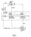
- Figure 1 used for illustrative purposes, is a simplified diagram of the invention which uses a single sending and receiving unit and a single pipe.
- the sending unit has a single client entity, which can be an application program or the like, and a single server entity, which, for example, may be an I/O device attached to a subsystem. It should be understood by those skilled in the art that, in practice, multiple sending and receiving units would be used, as well as multiple pipes, clients and servers.
- Figure 1 shows the general flow of data and control information in the invention.
- the sending and receiving units 102, 108 comprise a unit pair which may be a processor unit and a subsystem unit, or both may be subsystem units.
- a sending unit 102 will request that a receiving unit 108 perform some work by placing a control element 104 into shared memory 106 (the distributed pipe). Commands and control information are contained in the control element 104. If data is to be transferred from the sending unit 102 to the receiving unit 108, it can be transferred in one of two ways. First, it can be directly transferred within a variable length field of the control element 104. The control element, including the placement of data within the control element, will be discussed in more detail below. Second, it can be placed in the buffer 110 by the sending unit 102. The sending unit 102 will then place the address and length of the data contained by the buffer 110 into the control element 104 prior to sending the control element 104 to the distributed pipe 106.
- the actual movement of data into and out of the buffer, as well as the pipe can be accomplished by a number of conventional methods, well known in the art, such as through the use of DMA logic.
- DMA logic As a general rule, it is preferable to use the external buffer 110 to transfer data since the distributed pipe 106 has a finite size and could be rapidly filled by the large data transfers used in many applications.
- the sending unit 102 does not have to wait for the receiving unit 108 to respond.
- the sending unit 102 can proceed with other tasks including the placement of other work requests in the distributed pipe 106 in the form of control elements 104.
- the receiving unit 108 will retrieve control elements 104 from the pipe 106, execute the work request contained therein, and reply to the sending unit 102. If the control element 104 addresses data in the buffer 110, the receiving unit 108 will read or write the data from the buffer 110. When the work request is complete, the receiving unit will reply to the sending unit 102 by placing a control element 116 on the pipe 112.
- Control elements 104 and 116 are functionally identical, as are pipes 106 and 112. They are identified separately to denote that the pipe is physically located in different units of the system. In addition, the preferred embodiment uses logically separate pipes for sending and receiving control elements.) As was the case with the sending unit 102, the receiving unit 108 does not wait for a response from the sending unit 102. It can proceed immediately to other work, including the retrieval of more control elements 104 from the pipe 106.
- the sending unit When the sending unit retrieves the control element 116 from the pipe 112 which contains the reply to the sending unit's 102 request, it can take the appropriate action based on the reply.
- the logical steps discussed above are supported by the delivery support 118 (which includes a delivery send mechanism and a delivery receive mechanism) and the bus 114.
- the delivery support mechanism in the preferred embodiment is state logic well known in the art. Control information and data are physically moved to and from the sending and receiving units to the buffer 110 and the pipe 106, 112 by way of the bus 114. Further, the delivery support mechanism 118 includes the enqueue/dequeue logic (not shown) to control placement of control elements on the FIFO queue in pipe 106, 112.
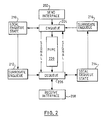
- Figures 2, 3, and 4 show the basic mechanism used by the invention for signalling, state logic, and interrupt handling.
- the basic flow of control elements shown in figure 2, operates using the send interface 202 and enqueue logic 204 to place control elements into a pipe 220. It then uses dequeue logic 206 and receive interface logic 208 to remove the control element from the pipe 220.
- the enqueue and dequeue logic use the state information shown in figure 3.
- the signalling is done by pushing state change surrogate state information to the surrogate enqueue logic 212, 216, then pushing reason codes to the reason area (shown in figure 4) for this unit.
- a hardware level primitive causes an interrupt (shown in figure 4).
- the hardware primitive may be either interrupt controller hardware or may be done by writing I/O ports or mapped memory locations which cause hardware interrupts.
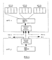
- Figure 5 shows a structure which is more representative of the invention in actual use than Figure 1. However, as in the discussion of Figure 1, the actual number of entities is not limited to the number of entities shown, but is instead a function of the hardware capacity of the particular system components in question.
- Figure 5 shows a processor unit 502 which includes multiple client entities 504, 506, 508, 510. Each entity may be a program or some other system task which requires interaction with subsystem units. The subsystems are represented in the figure as they would typically appear in practice, as adapter cards 512, 514. Each adapter 512, 514 in turn has multiple server entities 516, 518, 520, 522, 524, 526 which may be I/O devices such as communication lines, printers, terminals, or the like.
- Figure 5 also illustrates the use of multiple distributed pipes 528, 530, 532 within a shared memory 534.
- pipes for unit pairs can be used by processor/subsystem unit pairs 502/512 and 502/514, or by subsystem/subsystem unit pairs 512/514.
- Each of the pipes would move control elements 536 on the bus 114, as discussed above in the description of Figure 1.
- Figure 6 is a diagram showing the general arrangement of the invention which is designed to show the relationship between the circular pipe and the system.
- state information 606, 608, 610, 612, 614, 616, 618, 620 needed for the enqueueing and dequeueing of control elements (not shown).
- the state information is distributed between the two units 622, 624.
- the delivery support 626, 628, 630, 632 is shared between multiple entity to entity pairs 634, 636, 638, 640, 642, 644, 646, 648. Portions of the delivery support communicate with each other over the micro channel 650.
- Figure 7 shows the arrangement of fields in a control element. A general discussion of how the invention uses the control elements follows.
- Each work order consists of a control element used to describe the unit of work being requested, and one or more control elements used to indicate the completion or current state of the requested unit of work. Error conditions or changes in the processing state of a unit of work are reported in error and event control elements respectively.
- each of the following would be a valid work order: - a single request element with no reply element; - a single request element with a single reply element; - a single request element with multiple reply elements; - a single request element with an error element; - a single request element with an event element; - a single request element with both event and error elements; - a single request element with event, reply, and error elements.
- each request element in the chain is treated as one part of a single work order.
- Elements, or more precisely control elements are used to exchange control information and, in some cases, data between a client and a server. They are like an envelope with a see through window; allowing the delivery service to use information in the window to deliver the control elements without having to know or understand what is contained within the remainder of the control element.
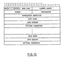
- a control element contains the following: - a 16 bit type field - a 16 bit length field - a 16 bit source field - a 16 bit destination field - a 32 bit correlation field - a variable length value field
- the first five fields are used by the delivery service as well as the client and server. It constitutes the information visible through the window in the envelope.
- the remaining field, the value field contains the contents of the envelope. It contains information meaningful only to the client and the server.
- the type field of an element is a 16 bit word used to identify an element and indicate how to interpret the remaining fields within the element.
- the type field consists of the following sub-elements: EID element identifier - a (2) bit sub-field used to identify the element type.
- EID element identifier - a (2) bit sub-field used to identify the element type.
- S suppress reply flag - indicates whether or not the client wants the server to return a reply element when the processing of this request element has been completed successfully. When set to one, the reply is suppressed and no reply element will be returned. When set to zero, whether or not a reply is returned is determined by the entity to entity protocol.
- C chaining flags - indicate whether or not command chaining is in effect. When chaining is in effect and all elements in the chain represent a single unit of work, to be processed in the order in which they appear.
- the following table indicates how the chain bits are to be interpreted: 00 - indicates no chaining (first and last) 01 - indicates the start of a command chain (first element) 11 - indicates an element within the chain (intermediate element) 10 - indicates the end of chain (last element)
- I indirect flag - indicates whether the value field of the element contains the parameters for the specified function or just the length of, and a pointer to, a data area where the actual parameters are stored. When set to one, the value field contains a pointer to the parameter value.
- N notification flag - indicates whether or not the client is requesting notification by the server when processing of this element begins. When set to one, a notification is to be returned to the client using a notification event element.
- W wait flag - indicates whether or not the client is requesting the server to wait before processing this request element, or any other request elements from this client, until it is told to do so with a subsequent resume event element from the client. When set to one, processing is to be suspended.
- E expedite flag - identifies a control element that the client wants the server to process as expeditiously as possible, i.e. before any other control elements that may be waiting to be processed. When set to one, the control element is to be expedited.
- FC function code - a seven (7) bit sub-field used to identify the function to be performed and indicate how to interpret the contents of the value field.
- the length field of an element is a 16 bit word used to specify the total length of the element in bytes. This includes 2 bytes for the type field, 2 bytes for the length field, 2 bytes for the source field, 2 bytes for the destination field, 4 bytes for the correlation field, and n bytes for the variable length value field.
- the source field is a 16 bit word used to identify the originator or source of an element. It is a structured field containing a unit identifier and an entity identifier.
- the unit id is the bus unit with an allowable range of 0 to 15, and the entity id is one of 256 possible sources. Entity id zero (0) is reserved for management purposes. Together, they provide sufficient information to unambiguously identify a bus unit as well as the entity within the bus unit responsible for originating the element.
- the destination a 16 bit word used to identify the target or destination of an element.
- the unit id is the bus unit with an allowable range of 0 to 15, and the entity id is one of 256 possible destinations. Entity id zero (0) is reserved for management purposes. Together, they provide sufficient information to unambiguously identify the bus unit and the entity within the bus unit who is the recipient of the element.
- the correlation field is a 32 bit doubleword used to provide an identifier for associating or correlating a response with a previous request.
- the format and content of the correlation identifier is determined by the entity who is the originator of the request. It may be a sequence number, the address of a control block or request packet, or the address of a data buffer.
- the correlation identifier is returned to the originator of the request in a reply, error, or event element.
- the value field of an element is a variable length field used to hold additional arguments, parameters, or data required by the operation identified by the function code in the type field.
- the type, length, and format of this information will vary depending on the function specified.
- a function code is used to identify the operation to be performed and to indicate how the contents of the value field should be interpreted.
- the High order bit of the function code is used to distinguish between common usage function codes and implementation defined function codes. When bit 6 is set to one (1), it indicates that the remaining bits (0 - 5) contain a non- architected function code.
- Function codes 0, 20 through 30, and 32 through 63 are reserved and should be treated as an error condition if found in a control element.
- the suspend, resume, notify, inform, and wrap function codes are used exclusively with the event element. All other function codes are used with request, reply, and error elements.
- the immediate SCB elements provide a path for certain forms of adapter migration. They allow the delivery service to be used with the existing SCB's.
- the format and content of this element is shown in figure 8.
- the Initialise function is found in request, reply, and error elements.
- a request element it invokes the initialisation function of the server.
- the source and destination, a correlation identifier, and the value field containing any additional parameters required by the server initialisation function are passed to the server in the request element.
- the initialisation parameters passed in the value field of the request element are server dependent and will need to be defined on a server by server basis.
- the value field does not contain the actual initialisation parameters, but instead contains the location and the length of a data area where the actual parameters themselves are stored.
- a server reports the successful completion of an initialisation request by returning a reply element to the requestor.
- the source and destination, the correlation identifier from the initialisation request element, and any return values are placed in the value field of the reply element.
- the return parameters passed in the value field of the reply element are server dependent and will need to be defined on a server by server basis.
- a client may choose to suppress the returning of a reply element by by setting the suppress flag in the Type Field of the initialisation request element.
- the source and destination, the correlation identifier from the initialisation request element, and status information identifying the cause of the failure are returned to the requestor in the value field of an error element.
- the base SCB elements provide a path for certain forms of adapter migration. They allow the delivery service to be used with the existing SCB's. The format and content of these elements is shown in figure 9.
- the Read function is found in request, reply, and error elements.
- a request element it is used to setup and initiate the transfer of data and control information from the server to a client.
- the source and destination, a correlation identifier, and the value field containing the parameters required by the server read function are passed to the server in the request element.
- the value field does not contain the byte count, data address and optional parameters, but instead contains the location and the length of a data area where they are stored.
- the server When the server has successfully completed the transfer, it returns a reply element with the source and destination, the correlation identifier from the read request element, and the actual number of bytes transferred in the value field of the reply element.
- a client may choose to suppress the returning of a reply element by setting the suppress flag in the Type Field of the read request element.
- the Read List function is found in request, reply, and error elements. It is used to setup and initiate the transfer of data and control information from a server into several possibly non-contiguous areas of memory. This is often referred to as data chaining.
- the source and destination, a correlation identifier, and the value field containing the list of byte count/data address pairs required by the read list function are passed to the server in the request element.
- the value field does not contain the list of byte counts and data address, but instead contains the location and the length of a area where the actual list is stored.
- the server When the server has successfully completed the transfer, it returns a reply element with the source and destination, the correlation identifier from the read list request element, and residual byte count in the value field of the reply element.
- the format and content of the read list reply element is the same as the read reply.
- a client may choose to suppress the returning of a reply element by setting the suppress flag in the Type Field of the read list request element.
- an error element containing the source and destination, the correlation identifier from the read list request element, and status information identifying the cause of the failure, are returned to the requestor in the value field of the error element.
- the format and content of the read list error element is the same as the read error.
- the Read Immediate function is found in request, reply, and error elements. It is used to request the transfer of data and/or control information from a server to a client. It differs from the read request in that the data is to be returned in the value field of the reply element where it will be immediately available to the client.
- the source and destination, a correlation identifier, and the value field containing the parameters required by the read immediate function, are all passed to the server in the request element.
- the amount of data that can be returned using the read immediate request element is configuration dependent. That is, it is directly related to the size of the delivery queue. Therefore, care should be exercised when using this request element.
- the server When the server has successfully completed the transfer, it returns a reply element with the source and destination, the correlation identifier from the read immediate request element and, in the value field, the actual number of bytes transferred followed immediately by the data itself.
- the read immediate function ignores the suppress flag if set in the Type Field of the read immediate request element since it always returns a reply element.
- an error element containing the source and destination, the correlation identifier from the read immediate request element, and status information identifying the cause of the failure, are returned to the requestor in the value field of the error element.
- the Write function is found in request, reply, and error elements. It is used to setup and initiate the transfer of data and control information from a client to a server.
- the source and destination, a correlation identifier, and the value field containing the amount and location of the data to be transferred by the write function, are all passed to the server in the request element.
- the value field does not contain the byte count, data address and optional parameters, but instead contains the location and the length of a data area where they are stored.
- the server When the server has successfully completed the transfer, it returns a reply element with the source and destination, the correlation identifier from the write request element, and the actual number of bytes transferred in the value field of the reply element.
- a client may choose to suppress the returning of a reply element by setting the suppress flag in the Type Field of the write request element.
- the Write List function is found in request, reply, and error elements. It is used to setup an initiate the transfer of data and control information to a server from several possibly non-contiguous areas of memory. This is often referred to as data chaining.
- the source and destination, a correlation identifier, and the value field containing the list of byte count/data address pairs required by the write list function, are all passed to the server in the request element.
- the value field does not contain the byte counts and data address, but instead contains the location and the length of an area where the actual list is stored.
- the server When the server has successfully completed the transfer, it returns a reply element with the source and destination, the correlation identifier from the write list request element, and residual byte count in the value field of the reply element.
- the format and content of the write list reply element is the same as the write reply.
- a client may choose to suppress the returning of a reply element by setting the suppress flag in the Type Field of the write list request element.
- an error element containing the source and destination, the correlation identifier from the write list request element, and status information identifying the cause of the failure, are returned to the requestor in the value field of the error element.
- the format and content of the write list error element is the same as the write error.
- the Write Immediate function is found in request, reply, and error elements. It is used to carry data and/or control information from a client to a server. It differs from the write request in that the data is present in the value field of the request element and is immediately available to the server. The source, destination, and correlation identifier, as well as the data itself, are all passed to the server in the request element.
- the amount of data that can be transferred using the write immediate request element is configuration dependent. That is, it is directly related to the size of the delivery queue. Therefore, care should be exercised when using this request element.
- the server When the server has successfully received the data, it returns a reply element with the source and destination, the correlation identifier from the write immediate request element and, in the value field, a count of the actual number of bytes received.
- a client may choose to suppress the returning of a reply element by setting the suppress flag in the Type Field of the write immediate request element.
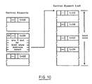
- Figure 10 shows an example of an execute list.
- the Execute List function is indicated in the type field of request and reply elements. It is used to setup a repetitive loop for executing a list of request elements pointed to by this element one or more times.
- the source and destination, a correlation identifier, and the value field containing the location, length, and count required by the execute list function, are all passed to the server in the request element.
- a list of requests to be executed may consist of one or more request elements which must be contiguous in memory. Each element in the list contains its own length field so that the start of the next element can easily be determined. The "length of list" field determines where the list ends. On each pass through the list, the repetition count is decremented by one, and if not zero, the list is executed again. If the initial repetition count is negative or zero the request terminates with no execution.
- the request elements that make up the list can contain any of the function codes defined in this section and use any of the optional flags available to them.
- the list is terminated and the server returns a reply element with the source, destination, and correlation identifier from the original execute list request element.
- a client may choose to suppress the returning of a reply element by setting the suppress flag in the Type Field of the execute list request element.
- the Mark function is used only in a request element to provide a means of marking or indicating a point of possible synchronisation between a client and a server. It performs no other function other than the passing of a correlation identifier to the server.
- the power of this function is in the way it can utilised the Notify and Wait flags to inform a client of the current processing state of the server.
- the Mark function ignores the indirect, suppress, and expedite flags if set in a mark request element.
- the Cancel function is used in request, reply, and error elements.
- a request element it is used to request the cancellation of one or more outstanding request elements.
- the source and destination, a correlation identifier, and the value field containing the cancellation qualifier and an optional list of request element correlation identifiers are all passed to the server in the request element.
- a cancellation list is present whenever bits 2 or 3 of the cancellation qualifier are set to one. If bit 1 is set, then bit 2 or 3 must also be set.
- the value field does not contain the cancellation list, but instead contains the location and the length of a data area where the actual list is stored.
- the server When the server has successfully completed the cancel function, it returns a reply element to the requestor.
- the source and destination, as well as the correlation identifier from the cancel request element are returned in the reply element.
- the server will attempt to cancel all requests whose correlation identifiers are in the value field of the cancel request. If for any reason the server is unable to do so, it will return an error element with status and a list of correlation identifiers for those it was able to cancel. An empty list indicates that it was unable to perform the cancel.
- the Reset function is used in request, reply, and error elements.
- a request element it is used to request the server be placed into a known state.
- the source and destination, a correlation identifier, and the value field containing the desired state, are all passed to the server in the request element.
- the server When the server has successfully completed the reset, it returns a reply element with the source and destination, the correlation identifier from the reset request element to the requestor.
- the reset function ignores the suppress and indirect flags if set in a reset request element.
- the Read Configuration function is used in request, reply, and error elements. When used in a request, it causes the server to return configuration information to the client.
- the source and destination, a correlation identifier, and the value field containing the byte count, data address, and optionally the specific configuration information to be returned, are passed to the server in the request element.
- the value field does not contain the optional parameters, but instead contains the location and the length of a data area where the actual parameters themselves are stored.
- a server reports the successful completion of a read configuration request by returning a reply element to the requestor.
- the source, destination, and correlation identifier from the read configuration request element are returned in the value field of the reply element.
- a client may choose to suppress the returning of a reply element by setting the suppress flag in the Type Field of the read configuration request element.
- the Diagnose function is used in request, reply, and error elements. In a request, it is used to initiate the running of diagnostic routines by a server.
- the source and destination, a correlation identifier, and the value field containing the specific diagnostic tests to be run as well as any operational parameters, are passed to the server in the request element.
- the value field does not contain the optional parameters, but instead contains the location and the length of a data area where the actual parameters themselves are stored.
- a server reports the results of running the diagnostic tests by returning a reply element to the requestor.
- the source and destination, correlation identifier from the diagnose request element, and the value field containing the test results are returned in the reply element.
- a client may choose to suppress the returning of a reply element by setting the suppress flag in the Type Field of the diagnose request element.
- a server If a server is unable to run the requested diagnostic test, a error element with the source and destination, the correlation identifier from the diagnose request element, and the value field containing the reason are returned to the requestor in the error element.
- the delivery service provides an element for conveying information about the progress of a request, or about the side-effects of a previous request, or about the state of an entity - the event element.
- the event element differs from the other elements in that it it reports a change in state of one of the communicating entities (client or server). Because of the impact of these state changes, the peer-entity must be informed of the change as expeditiously as possible.
- the following sections describe the format, content and usage of the functions codes of an event element.
- a suspended event is used to notify a client of a change in processing state at the server.
- a server changes state whenever it receives a request element from a client in which the wait flag of the type field is set to one.
- the server suspends the processing of the request and all subsequent requests from the specified source. This change of state is communicated to the the client by means of a suspend event element.
- the source and destination, as well as the correlation identifier of the request element causing the suspension, are returned to the client in the value field of the event element.
- a resume event is used to notify a server of a change in a clients processing state.
- a client uses this event to notify a server that the client is now in a state where the processing of request elements can now be resumed.
- the source and destination, as well as the correlation identifier of the original request element causing the suspension, are returned to the server in the value field of the resume event.
- a resume event received from a source other than the one responsible for the suspended state or the receipt of a resume for a destination that is not in the suspended state, will be ignored.
- a notification event is used to confirm the receipt of a request element from a client in which the notification flag of the type field is set to one.
- the server communicates this to the client by means of a notification event element.
- the source and destination, as well as the correlation identifier of the request element containing the notification flag, are returned to the client in the value field of of the event element.
- An inform event is used to provide a means of conveying information regarding the processing state of either a client or a server from one to other.
- a wrap event is a management and control initiated event used internally by the delivery system. It is used to synchronise the operations associated with the in-bound or out-bound delivery pipes (queues).
- a wrap event element can be sent only by a delivery agent.
- the wrap event informs the destination delivery agent that the associated delivery queue has wrapped and that the next element should be dequeued from the top of the delivery queue.
- the processing of request elements by a server may take place either synchronously or asynchronously depending on whether or not command chaining is in effect.
- a server may process requests in any order that makes sense to the server (asynchronously).
- a client wishes to have the server process the requests in the order in which they have been submitted (synchronously).
- SCB architecture supports two methods of data chaining: direct and indirect.
- each non-contiguous data area is described by an entry in a chaining list.
- the entry contains a byte count and an address pointer to a data area. After each data area described by an entry is transferred, the next entry in the list is processed. This action continues, until all the entries in the list have been processed, or no more data exits.
- Direct data chaining is invoked through the use of the Read List and Write List function codes. The format of a read list element for direct data chaining is shown in figure 12.
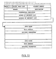
- Indirect data chaining is similar to direct data chaining except for the location of the chaining list.
- the list is not part of the request element. Instead the list is kept separate and is referenced by means of a indirect list pointer in the value field of the request element.
- Indirect data chaining is invoked by setting the indirect flag in a Read or Write List request element.
- the format of a read list element for indirect data chaining is shown in figure 13.
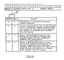
- a client can request notification when an element is about to be processed by setting the notification flag in the type field of the appropriate request element. This causes the server to return a event notification element with the source, destination, and correlation identifier of the element containing the notification flag in its value field to the client.
- a client can suspend the processing of a set of request elements at a particular point in the list by setting the wait flag in the type field of the appropriate request element prior to submitting it to the Delivery Service This causes the server to suspend further processing of request elements, to return an event notification element with the correlation identifier of the element containing the suspend flag in its value field, and to wait for a resume event from the originating client before continuing.
- the original request element containing the wait flag is not processed until the resume event is received from the client.
- Figure 14 shows the various combinations of usage for notification and wait.
Abstract
Description
- The present invention relates to a computer system, and in particular is directed to a command delivery mechanism for a computer system. Specifically, the invention is directed to asynchronously delivering commands, replies, and status information between a personal computer class machine and a plurality of intelligent subsystems which may have attached devices.
- In a data processing or computer system comprised of a host system and at least one subsystem, there is a need to communicate direct and indirect commands to an individual subsystem, usually over an Input Output (I/O) channel.
- The direct Command is one which can be directly sent to a subsystem in one operation, is completely and totally self-contained, and totally specifies an operation to be executed by the subsystem. On the other hand, an indirect command is one which requires more data to specify the operation than can be provided within one channel I/O cycle. The indirect command is itself a pointer to a block of system memory which contains all the parameters necessary to totally specify an operation to be performed by the subsystem. This block of memory is often referred to as a "control block".
- In a typical prior art computer system, the interface bus overhead involved with the transfer of control blocks limited the throughput capacity of subsystems and their respective I/O. The limitation is caused by the inability of the processor and the subsystem to form a synchronous connection on the bus due to other competing subsystems or processor tasks. Processor peformance was impaired due to the inability of the processor to obtain service from adapters and I/O, and the performance of the adapters and I/O was impaired by the ability of the processor to send and receive data as quickly as the adapters and I/O were capable of processing it. As a result, there was a need to eliminate the bottleneck at the interface bus which allowed neither the processor nor the adapters and their respective I/O to perform as well as their hardware would allow.
- An aim of the present invention is provide a computer system in which control information and data can be selectively transferred between a processor and subsystems on an asynchronous or synchronous basis.
- In accordance with the present invention, there is now provided a computer system having a bus interface comprising a distributed pipe. The pipe allows a processor to asynchronously send and receive control blocks (for the purposes of this disclosure, the control blocks will hereinafter be referred to as control elements) for direct and indirect commands without requiring intervention by an adapter or I/O device. Likewise, the adapters and I/O can asynchronously send and receive control elements to the pipe without intervention by the processor. In addition, the pipe allows subsystem to subsystem control element transfer independent of processor intervention.
- Viewing the present invention from a second aspect, there is now provided a computer system comprising: a first unit type having at least one processor; a second unit type having at least one subsystem, which may have attached devices; an interface bus for interconnecting with each of the unit types; characterised in that the system further comprises: a distributed pipe comprising shared memory distributed among each of the unit types; each of the unit types further comprising: at least one entity; delivery send means for asynchronously sending control elements, addressed to another entity from the entity, to the distributed pipe without interaction with any other entity; and delivery receive means for asynchronously receiving control elements, addressed to the entity, from the distributed pipe without interaction with any other entity.
- Viewing the present invention from an third aspect, there is now provided, in or for a computer system, a method for transferring control elements representing requests, replies, or asynchronous notification between units in the system, comprising: interconnecting units, including at least one subsystem, with an interface bus; sharing memory physically distributed between the units as a distributed pipe; sending control elements from a sending unit, representative of requests and replies, and addressed to a receiving unit, to the distributed pipe without interaction with any other unit; and receiving control elements, addressed to a receiving unit, from the distributed pipe without interaction with any other unit; wherein the control elements are asynchronously transferred from one of the units to another of the units through the distributed pipe.
The interconnecting units preferably include at least one processor. - Preferably, the control elements can be written to and read from the distributed pipe as a circular queue. In another preferred example, the control elements are written to and read from the distributed pipe as a FIFO queue.
- A preferred method of the present invention includes the step of signalling the receiving means with the sending means when a control element is placed on the distributed pipe. Preferably, the step of signalling the delivery receive means with the delivery send means to examine the state of the distributed pipe at predetermined time intervals. The step of using a management entity in each the unit to control interaction of the unit with the distributed pipe is also preferably included..
- The control elements are preferably configured with a fixed length portion and a variable length portion, the fixed length portion further comprising a type field for describing the type of information in the control element, a length field containing the length of the control element, a source field describing the source of the control element, a destination field describing the destination of the control element, and a correlation field for correlating requests with replies. In a preferred method of the present invention, there is accordingly provided the further step of the transferring data in the variable length portion. There may also be provided the further steps of inserting a command for immediate execution by an attached device in the variable length portion; and inserting an immediate command identifier in the type field; whereby the entity sending the immediate command can encapsulate commands within a control element and pass the immediate command through the distributed pipe. There may further be provided the step of using at least one buffer storage, in the unit containing the entity sending the control element, for holding data external to the distributed pipe, and further identifying the location of data in the buffer with field in the control element.
- A preferred method of the present invention includes the additional step of inserting the address of a buffer location containing a command for immediate execution by an attached device in the variable length portion; and inserting an immediate command identifier in the type field; whereby the entity sending the immediate command can encapsulate commands within a control element and pass the immediate command through the distributed pipe.
- Preferably, a plurality of requests are concatenated in an execution list by; configuring the variable length field to indicate the length of the execute list, indicating the address of the execute list, and indicating the number of times the execute list is to be repeated; and placing an execute list identifier in the type field of the control element.
- The sending and receiving units are preferably synchronised during execution of the execute list by manipulating notify and wait bits in the type field by the sending and receiving units to indicate to each of the sending and receiving units the status of the other unit.
- A preferred method of the present invention includes the step of using the delivery send means to detect when the distributed pipe is full. Another preferred method includes the step of using the delivery send means to detect when available space in the distributed pipe is insufficient to hold another control element. The latter method preferably comprises the additional step of placing a wrap element at the end of the distributed pipe space when the distributed pipe does not have available space for another control element, the wrap element indicating to the delivery receive means the end of available pipe space; whereby the delivery receive means resets to the start of the pipe space.
- A preferred method of the present invention comprises the step detecting when the distributed pipe changes from the empty state to the not empty state. Preferably, the step of using the delivery receive means to detect when the distributed pipe is empty is included.
- A preferred example of the present invention uses a plurality of distributed pipes. Accordingly, a preferred method of the present invention includes the additional step of using a pair of distributed pipes for each unit pair, using the first distributed pipe for control elements sent from a first unit of the unit pair to a second unit of the unit pair, and using a second distributed pipe for control elements sent from the second unit of the unit pair to the first unit of the unit pair; whereby each of the unit pairs operate in full duplex mode.
- In an example of the present invention, there is provided a computer system in which control information and data can be transferred between a processor and an attached subsystem independent of the availability of the attached subsystem. Similarly, the control information and data can also be transferred between the subsystem and the processor independent of the availability of the processor. The control information and data can be asynchronously transferred between the processor and attached subsystems in full duplex mode. Furthermore, the control information and data can be transferred between subsystems of a computer system without intervention of the processor. Also, the control information and data can be transferred between a processor and a multiplicity of different subsystems on a common interface. The computer system of the present invention thus enables control information and data to be transferred between a processor and attached subsystems in an improved manner.
- In a preferred example of the present invention to be described later, there is provided a computer system having a distributed shared memory, which is located in the processor and the subsystems, to form a distributed pipe organised as a FIFO circular queue. Control elements are asynchronously placed on the pipe by the processor and by the subsystems. Each control element contains a fixed field carrying self describing information including the source and destination. A variable field follows the fixed field, and may contain data or a pointer to a buffer external to the pipe which can contain data or a list of commands to be executed (i.e., indirect commands). The fixed field also contains control bits which allow the subsystem and the processor to synchronously execute a repetitive list of control elements when necessary. The asynchronous sending and receiving of control elements to and from the pipe allows the processor and the subsystems to be free running, thereby avoiding interrupt delays. In addition, a common interface is achieved by the control element structure which allows different subsystem types to use the same pipe.
- A preferred embodiment of the present invention will now be described with reference to the accompanying drawings in which:
- Figure 1 is a simplified diagram of the invention using a single sending unit and a single receiving unit.
- Figure 2 is a overview diagram of the signalling mechanism used to notify units of the system.
- Figure 3 is a block diagram of the state information used by the signalling mechanism in figure 2.
- Figure 4 is a diagram of the interrupt logic used by the system.
- Figure 5 is a diagram of the invention using multiple subsystems and entities.
- Figure 6 is another diagram of the invention using multiple subsystems and entities, which also shows the delivery send mechanism and the delivery receive mechanism.
- Figure 7 is a diagram of a control element.
- Figure 8 is a diagram of an immediate SCB command.
- Figure 9 is a diagram of a base SCB.
- Figure 10 is a diagram of an execute list.
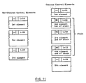
- Figure 11 is a diagram of the control elements used for command chaining.
- Figure 12 is a diagram showing the format of a read list request.
- Figure 13 is a diagram showing the format of control blocks used for indirect data chaining.
- Figure 14 is a diagram showing the location of the notify and wait bits.
- By way of general overview, the invention allows a processor and a subsystem to asynchronously transfer data and control information and thereby avoid interrupt delays which degrade performance of the processor and the subsystem. In addition, the data and control information can also be asynchronously transferred between subsystems without processor intervention. The microprocessor system which includes a processor unit with system memory and a separate buffer memory, one or more subsystem adapter units with memory, optional I/O devices which may attach to the adapters, and a bus interface (which can interchangeably be called a micro channel). The memory in the processor and the memory in the adapters are used by the system as a shared memory which is configured as a distributed FIFO circular queue (a pipe). Unit to unit asynchronous communication is accomplished by placing control elements on the pipe which represent requests, replies, and status information. The units send and receive control elements independent of the other units which allows free flowing asynchronous delivery of control information and data between units. The shared memory can be organised as pipe pairs between each pair of units to allow full duplex operation by using one pipe for outbound control elements and the other pipe for inbound control elements. The control elements have standard fixed header fields with variable fields following the fixed header. The fixed header allows a common interface protocol to be used by different hardware adapters. The combination of the pipe and the common interface protocol allows many different types of hardware adapters to asynchronously communicate, resulting in higher overall throughput due to lower interrupt overhead.
- An important feature of the invention is the use of a shared memory to hold the control information. The shared memory used to hold the control information is physically distributed between the processor and the subsystems and will hereafter be interchangeably referred to as a distributed pipe or a pipe. A unit of the system, such as a processor or subsystem adapter, can send self-describing control elements to the distributed pipe for later retrieval by another unit. The control elements carry commands, data, or addresses of data stored in a buffer which is external to the pipe. The unit of the system which is intended to receive the control element will retrieve it from the pipe as soon as it can, but does not require the sending unit to wait for the receiving unit to act. The sending unit can, therefore, place the control element in the distributed pipe and proceed to other work rather than waiting for a response from the other unit.
- Figure 1, used for illustrative purposes, is a simplified diagram of the invention which uses a single sending and receiving unit and a single pipe. In addition, the sending unit has a single client entity, which can be an application program or the like, and a single server entity, which, for example, may be an I/O device attached to a subsystem. It should be understood by those skilled in the art that, in practice, multiple sending and receiving units would be used, as well as multiple pipes, clients and servers. Figure 1 shows the general flow of data and control information in the invention. The sending and receiving
units 102, 108 comprise a unit pair which may be a processor unit and a subsystem unit, or both may be subsystem units. A sendingunit 102, will request that a receiving unit 108 perform some work by placing acontrol element 104 into shared memory 106 (the distributed pipe). Commands and control information are contained in thecontrol element 104. If data is to be transferred from the sendingunit 102 to the receiving unit 108, it can be transferred in one of two ways. First, it can be directly transferred within a variable length field of thecontrol element 104. The control element, including the placement of data within the control element, will be discussed in more detail below. Second, it can be placed in thebuffer 110 by the sendingunit 102. The sendingunit 102 will then place the address and length of the data contained by thebuffer 110 into thecontrol element 104 prior to sending thecontrol element 104 to the distributed pipe 106. It should be understood that the actual movement of data into and out of the buffer, as well as the pipe, can be accomplished by a number of conventional methods, well known in the art, such as through the use of DMA logic. As a general rule, it is preferable to use theexternal buffer 110 to transfer data since the distributed pipe 106 has a finite size and could be rapidly filled by the large data transfers used in many applications. At this point, the sendingunit 102 does not have to wait for the receiving unit 108 to respond. The sendingunit 102 can proceed with other tasks including the placement of other work requests in the distributed pipe 106 in the form ofcontrol elements 104. - The receiving unit 108 will retrieve
control elements 104 from the pipe 106, execute the work request contained therein, and reply to the sendingunit 102. If thecontrol element 104 addresses data in thebuffer 110, the receiving unit 108 will read or write the data from thebuffer 110. When the work request is complete, the receiving unit will reply to the sendingunit 102 by placing acontrol element 116 on the pipe 112. (Control elements unit 102, the receiving unit 108 does not wait for a response from the sendingunit 102. It can proceed immediately to other work, including the retrieval ofmore control elements 104 from the pipe 106. - When the sending unit retrieves the
control element 116 from the pipe 112 which contains the reply to the sending unit's 102 request, it can take the appropriate action based on the reply. - The logical steps discussed above are supported by the delivery support 118 (which includes a delivery send mechanism and a delivery receive mechanism) and the
bus 114. The delivery support mechanism in the preferred embodiment is state logic well known in the art. Control information and data are physically moved to and from the sending and receiving units to thebuffer 110 and the pipe 106, 112 by way of thebus 114. Further, the delivery support mechanism 118 includes the enqueue/dequeue logic (not shown) to control placement of control elements on the FIFO queue in pipe 106, 112. - Figures 2, 3, and 4 show the basic mechanism used by the invention for signalling, state logic, and interrupt handling. The basic flow of control elements, shown in figure 2, operates using the
send interface 202 andenqueue logic 204 to place control elements into apipe 220. It then uses dequeue logic 206 and receiveinterface logic 208 to remove the control element from thepipe 220. The enqueue and dequeue logic use the state information shown in figure 3. There is alsologic 210, 214 to recognise certain state changes in the pipe and to signal the other side. The signalling is done by pushing state change surrogate state information to thesurrogate enqueue logic 212, 216, then pushing reason codes to the reason area (shown in figure 4) for this unit. Once the surrogate information and reason information is pushed, a hardware level primitive causes an interrupt (shown in figure 4). The hardware primitive may be either interrupt controller hardware or may be done by writing I/O ports or mapped memory locations which cause hardware interrupts. - Figure 5 shows a structure which is more representative of the invention in actual use than Figure 1. However, as in the discussion of Figure 1, the actual number of entities is not limited to the number of entities shown, but is instead a function of the hardware capacity of the particular system components in question. Figure 5 shows a processor unit 502 which includes
multiple client entities 504, 506, 508, 510. Each entity may be a program or some other system task which requires interaction with subsystem units. The subsystems are represented in the figure as they would typically appear in practice, asadapter cards adapter multiple server entities pipes 528, 530, 532 within a sharedmemory 534. As shown, pipes for unit pairs can be used by processor/subsystem unit pairs 502/512 and 502/514, or by subsystem/subsystem unit pairs 512/514. Each of the pipes would movecontrol elements 536 on thebus 114, as discussed above in the description of Figure 1. - Figure 6 is a diagram showing the general arrangement of the invention which is designed to show the relationship between the circular pipe and the system. There are a pair of
circular pipes 602, 604 which deliver control elements in opposite directions. The basic operation of each is the same. There isstate information units 622, 624. Thedelivery support micro channel 650. - Figure 7 shows the arrangement of fields in a control element. A general discussion of how the invention uses the control elements follows.
- Requests and the replies to those requests, are exchanged between clients (entities) in a system unit or adapter, and servers (entities) in an adapter or system unit using the delivery services of the SCB architecture. These requests, as well as their corresponding replies, are referred to as work orders. Each work order consists of a control element used to describe the unit of work being requested, and one or more control elements used to indicate the completion or current state of the requested unit of work. Error conditions or changes in the processing state of a unit of work are reported in error and event control elements respectively. Using this definition, each of the following would be a valid work order:
- a single request element with no reply element;
- a single request element with a single reply element;
- a single request element with multiple reply elements;
- a single request element with an error element;
- a single request element with an event element;
- a single request element with both event and error elements;
- a single request element with event, reply, and error elements. - When request elements are chained together, each request element in the chain is treated as one part of a single work order.
- Elements, or more precisely control elements, are used to exchange control information and, in some cases, data between a client and a server. They are like an envelope with a see through window; allowing the delivery service to use information in the window to deliver the control elements without having to know or understand what is contained within the remainder of the control element. Typically, a control element contains the following:
- a 16 bit type field
- a 16 bit length field
- a 16 bit source field
- a 16 bit destination field
- a 32 bit correlation field
- a variable length value field - The first five fields are used by the delivery service as well as the client and server. It constitutes the information visible through the window in the envelope. The remaining field, the value field, contains the contents of the envelope. It contains information meaningful only to the client and the server.
- The following sections describe in more detail, the format and content of each of these fields as it pertains to the delivery service.
- The type field of an element is a 16 bit word used to identify an element and indicate how to interpret the remaining fields within the element. The type field consists of the following sub-elements:
EID element identifier - a (2) bit sub-field used to identify the element type. There are four element types: - 1 - request (00) - An element sent by a client to a server asking it to perform a unit of work on its behalf. It requires the transfer of data and control information between a client and the server.
- 2 - reply (01) - An element sent by a server in response to certain request elements. Not all request elements are answered by replies, only those that request information.
- 3 - event (10) - An element containing information about the progress of a request, about the side- effects of a previous request or about the status of an entity. Events may be sent by either a server or a client.
- 4 - error (11) - An element that provides error information about a previous request, or about the health and welfare of a server or delivery agent.
- S suppress reply flag - indicates whether or not the client wants the server to return a reply element when the processing of this request element has been completed successfully. When set to one, the reply is suppressed and no reply element will be returned. When set to zero, whether or not a reply is returned is determined by the entity to entity protocol.
- C chaining flags - indicate whether or not command chaining is in effect. When chaining is in effect and all elements in the chain represent a single unit of work, to be processed in the order in which they appear. The following table indicates how the chain bits are to be interpreted:
00 - indicates no chaining (first and last)
01 - indicates the start of a command chain (first element)
11 - indicates an element within the chain (intermediate element)
10 - indicates the end of chain (last element) - I indirect flag - indicates whether the value field of the element contains the parameters for the specified function or just the length of, and a pointer to, a data area where the actual parameters are stored. When set to one, the value field contains a pointer to the parameter value.
- N notification flag - indicates whether or not the client is requesting notification by the server when processing of this element begins. When set to one, a notification is to be returned to the client using a notification event element.
- W wait flag - indicates whether or not the client is requesting the server to wait before processing this request element, or any other request elements from this client, until it is told to do so with a subsequent resume event element from the client. When set to one, processing is to be suspended.
- E expedite flag - identifies a control element that the client wants the server to process as expeditiously as possible, i.e. before any other control elements that may be waiting to be processed. When set to one, the control element is to be expedited.
- FC function code - a seven (7) bit sub-field used to identify the function to be performed and indicate how to interpret the contents of the value field.
- The length field of an element is a 16 bit word used to specify the total length of the element in bytes. This includes 2 bytes for the type field, 2 bytes for the length field, 2 bytes for the source field, 2 bytes for the destination field, 4 bytes for the correlation field, and n bytes for the variable length value field.
- The source field is a 16 bit word used to identify the originator or source of an element. It is a structured field containing a unit identifier and an entity identifier. For the Micro Channel, the unit id is the bus unit with an allowable range of 0 to 15, and the entity id is one of 256 possible sources. Entity id zero (0) is reserved for management purposes. Together, they provide sufficient information to unambiguously identify a bus unit as well as the entity within the bus unit responsible for originating the element.
- The destination a 16 bit word used to identify the target or destination of an element. Like the source field, it to is a structured field containing a unit identifier and an entity identifier For the Micro Channel, the unit id is the bus unit with an allowable range of 0 to 15, and the entity id is one of 256 possible destinations. Entity id zero (0) is reserved for management purposes. Together, they provide sufficient information to unambiguously identify the bus unit and the entity within the bus unit who is the recipient of the element.
- The correlation field is a 32 bit doubleword used to provide an identifier for associating or correlating a response with a previous request. The format and content of the correlation identifier is determined by the entity who is the originator of the request. It may be a sequence number, the address of a control block or request packet, or the address of a data buffer. The correlation identifier is returned to the originator of the request in a reply, error, or event element.
- The value field of an element is a variable length field used to hold additional arguments, parameters, or data required by the operation identified by the function code in the type field. The type, length, and format of this information will vary depending on the function specified.
- Within an element, a function code is used to identify the operation to be performed and to indicate how the contents of the value field should be interpreted. The High order bit of the function code is used to distinguish between common usage function codes and implementation defined function codes. When
bit 6 is set to one (1), it indicates that the remaining bits (0 - 5) contain a non- architected function code. When set to zero (0),bit 6 indicates that the remaining bits (0 - 5) contain one of the following common usage function codes:
- Immediate SCB Command (FC=1)
- Initialise (FC=2)
- Base SCB Command (FC=3)
- Read (FC=4)
- Read List (FC=5)
- Read Immediate (FC=6)
- Write (FC=7)
- Write List (FC=8)
- Write Immediate (FC=9)
- Execute List (FC=10)
- Mark (FC=11)
- Cancel (FC=12)
- Reset (FC=13)
- Read Configuration (FC=14)
- Diagnose (FC=15)
- Suspend (FC=16)
- Resume (FC=17)
- Notify (FC=18)
- Inform (FC=19)
- Wrap (FC=31) -
Function codes 0, 20 through 30, and 32 through 63 are reserved and should be treated as an error condition if found in a control element. - The suspend, resume, notify, inform, and wrap function codes are used exclusively with the event element. All other function codes are used with request, reply, and error elements.
- The following sections describe in detail the format, content and usage of the above functions in the various element types of the extended SCB architecture support.
-
- The immediate SCB elements provide a path for certain forms of adapter migration. They allow the delivery service to be used with the existing SCB's. The format and content of this element is shown in figure 8.
- The Initialise function is found in request, reply, and error elements. In a request element, it invokes the initialisation function of the server. The source and destination, a correlation identifier, and the value field containing any additional parameters required by the server initialisation function are passed to the server in the request element. The initialisation parameters passed in the value field of the request element are server dependent and will need to be defined on a server by server basis.
- If the indirect flag is set in the type field of the initialisation request element, the value field does not contain the actual initialisation parameters, but instead contains the location and the length of a data area where the actual parameters themselves are stored.
- A server reports the successful completion of an initialisation request by returning a reply element to the requestor. The source and destination, the correlation identifier from the initialisation request element, and any return values are placed in the value field of the reply element.
- The return parameters passed in the value field of the reply element are server dependent and will need to be defined on a server by server basis.
- A client may choose to suppress the returning of a reply element by by setting the suppress flag in the Type Field of the initialisation request element.
- If unsuccessful, the source and destination, the correlation identifier from the initialisation request element, and status information identifying the cause of the failure are returned to the requestor in the value field of an error element.
- The base SCB elements provide a path for certain forms of adapter migration. They allow the delivery service to be used with the existing SCB's. The format and content of these elements is shown in figure 9.
- The Read function is found in request, reply, and error elements. In a request element, it is used to setup and initiate the transfer of data and control information from the server to a client. The source and destination, a correlation identifier, and the value field containing the parameters required by the server read function are passed to the server in the request element.
- It should be noted that the parameters contained in the value field of a request element are not limited to those identified above. Additional parameters may be supplied to meet the requirements of each client/server relationship.
- If the indirect flag is set in the type field of the read request element, the value field does not contain the byte count, data address and optional parameters, but instead contains the location and the length of a data area where they are stored. When the server has successfully completed the transfer, it returns a reply element with the source and destination, the correlation identifier from the read request element, and the actual number of bytes transferred in the value field of the reply element.
- A client may choose to suppress the returning of a reply element by setting the suppress flag in the Type Field of the read request element.
- If unsuccessful, an error element containing the source and destination, the correlation identifier from the read request element, and status information identifying the cause of the failure, are returned to the requestor in the value field of the error element.
- The Read List function is found in request, reply, and error elements. It is used to setup and initiate the transfer of data and control information from a server into several possibly non-contiguous areas of memory. This is often referred to as data chaining. The source and destination, a correlation identifier, and the value field containing the list of byte count/data address pairs required by the read list function are passed to the server in the request element.
- If the indirect flag is set in the type field of the read list request element, the value field does not contain the list of byte counts and data address, but instead contains the location and the length of a area where the actual list is stored.
- When the server has successfully completed the transfer, it returns a reply element with the source and destination, the correlation identifier from the read list request element, and residual byte count in the value field of the reply element. The format and content of the read list reply element is the same as the read reply.
- A client may choose to suppress the returning of a reply element by setting the suppress flag in the Type Field of the read list request element.
- If unsuccessful, an error element containing the source and destination, the correlation identifier from the read list request element, and status information identifying the cause of the failure, are returned to the requestor in the value field of the error element. The format and content of the read list error element is the same as the read error.
- The Read Immediate function is found in request, reply, and error elements. It is used to request the transfer of data and/or control information from a server to a client. It differs from the read request in that the data is to be returned in the value field of the reply element where it will be immediately available to the client. The source and destination, a correlation identifier, and the value field containing the parameters required by the read immediate function, are all passed to the server in the request element.
- The amount of data that can be returned using the read immediate request element is configuration dependent. That is, it is directly related to the size of the delivery queue. Therefore, care should be exercised when using this request element.
- When the server has successfully completed the transfer, it returns a reply element with the source and destination, the correlation identifier from the read immediate request element and, in the value field, the actual number of bytes transferred followed immediately by the data itself.
- The read immediate function ignores the suppress flag if set in the Type Field of the read immediate request element since it always returns a reply element.
- If unsuccessful, an error element containing the source and destination, the correlation identifier from the read immediate request element, and status information identifying the cause of the failure, are returned to the requestor in the value field of the error element.
- The Write function is found in request, reply, and error elements. It is used to setup and initiate the transfer of data and control information from a client to a server. The source and destination, a correlation identifier, and the value field containing the amount and location of the data to be transferred by the write function, are all passed to the server in the request element.
- It should be noted that the parameters contained in the value field of a request element are not limited to those identified above. Additional parameters may be supplied to meet the requirements of each client/server relationship.
- If the indirect flag is set in the type field of the write request element, the value field does not contain the byte count, data address and optional parameters, but instead contains the location and the length of a data area where they are stored.
- When the server has successfully completed the transfer, it returns a reply element with the source and destination, the correlation identifier from the write request element, and the actual number of bytes transferred in the value field of the reply element.
- A client may choose to suppress the returning of a reply element by setting the suppress flag in the Type Field of the write request element.
- If unsuccessful, an error element containing the source and destination, the correlation identifier from the write request element, and status information identifying the cause of the failure, are returned to the requestor in the value field of the error element.
- The Write List function is found in request, reply, and error elements. It is used to setup an initiate the transfer of data and control information to a server from several possibly non-contiguous areas of memory. This is often referred to as data chaining. The source and destination, a correlation identifier, and the value field containing the list of byte count/data address pairs required by the write list function, are all passed to the server in the request element.
- If the indirect flag is set in the type field of the write list request element, the value field does not contain the byte counts and data address, but instead contains the location and the length of an area where the actual list is stored.
- When the server has successfully completed the transfer, it returns a reply element with the source and destination, the correlation identifier from the write list request element, and residual byte count in the value field of the reply element. The format and content of the write list reply element is the same as the write reply.
- A client may choose to suppress the returning of a reply element by setting the suppress flag in the Type Field of the write list request element.
- If unsuccessful, an error element containing the source and destination, the correlation identifier from the write list request element, and status information identifying the cause of the failure, are returned to the requestor in the value field of the error element. The format and content of the write list error element is the same as the write error.
- The Write Immediate function is found in request, reply, and error elements. It is used to carry data and/or control information from a client to a server. It differs from the write request in that the data is present in the value field of the request element and is immediately available to the server. The source, destination, and correlation identifier, as well as the data itself, are all passed to the server in the request element.
- The format as well as the meaning of the data contained in the value field of the request element are client/server dependent and as such are not defined here.
- The amount of data that can be transferred using the write immediate request element is configuration dependent. That is, it is directly related to the size of the delivery queue. Therefore, care should be exercised when using this request element.
- When the server has successfully received the data, it returns a reply element with the source and destination, the correlation identifier from the write immediate request element and, in the value field, a count of the actual number of bytes received.
- A client may choose to suppress the returning of a reply element by setting the suppress flag in the Type Field of the write immediate request element.
- If unsuccessful, an error element containing the source and destination, the correlation identifier from the write immediate request element, and status information identifying the cause of the failure, are returned to the requestor in the value field of the error element.
- Figure 10 shows an example of an execute list. The Execute List function is indicated in the type field of request and reply elements. It is used to setup a repetitive loop for executing a list of request elements pointed to by this element one or more times. The source and destination, a correlation identifier, and the value field containing the location, length, and count required by the execute list function, are all passed to the server in the request element.
- A list of requests to be executed may consist of one or more request elements which must be contiguous in memory. Each element in the list contains its own length field so that the start of the next element can easily be determined. The "length of list" field determines where the list ends. On each pass through the list, the repetition count is decremented by one, and if not zero, the list is executed again. If the initial repetition count is negative or zero the request terminates with no execution.
- The request elements that make up the list can contain any of the function codes defined in this section and use any of the optional flags available to them.
- When the repetition count goes to zero, the list is terminated and the server returns a reply element with the source, destination, and correlation identifier from the original execute list request element.
- A client may choose to suppress the returning of a reply element by setting the suppress flag in the Type Field of the execute list request element.
- Should an error occur while processing any element within the list, the list will be terminated. The error element returned, however, will be that of the offending request element.
- The Mark function is used only in a request element to provide a means of marking or indicating a point of possible synchronisation between a client and a server. It performs no other function other than the passing of a correlation identifier to the server.
- The power of this function is in the way it can utilised the Notify and Wait flags to inform a client of the current processing state of the server.
- The Mark function ignores the indirect, suppress, and expedite flags if set in a mark request element.
- The Cancel function is used in request, reply, and error elements. In a request element, it is used to request the cancellation of one or more outstanding request elements. The source and destination, a correlation identifier, and the value field containing the cancellation qualifier and an optional list of request element correlation identifiers are all passed to the server in the request element.
- The cancellation qualifier bits define which request elements are to be cancelled:
- all outstanding requests - (bit 0 = 1)
- requests that match the source ID - (bit 1 = 1)
- first request matching the cancellation list value(s) - (bit 2 = 1)
- all requests matching the cancellation list values(s) - (bit 3 = 1) - A cancellation list is present whenever
bits bit 1 is set, then bit 2 or 3 must also be set. - If the indirect flag is set in the type field of the cancel request element, the value field does not contain the cancellation list, but instead contains the location and the length of a data area where the actual list is stored.
- When the server has successfully completed the cancel function, it returns a reply element to the requestor. The source and destination, as well as the correlation identifier from the cancel request element are returned in the reply element.
- The server will attempt to cancel all requests whose correlation identifiers are in the value field of the cancel request. If for any reason the server is unable to do so, it will return an error element with status and a list of correlation identifiers for those it was able to cancel. An empty list indicates that it was unable to perform the cancel.
- However, a cancel request element with the all outstanding elements qualifier will not return an error element with the list of cancelled elements.
- The Reset function is used in request, reply, and error elements. In a request element, it is used to request the server be placed into a known state. The source and destination, a correlation identifier, and the value field containing the desired state, are all passed to the server in the request element.
- When the server has successfully completed the reset, it returns a reply element with the source and destination, the correlation identifier from the reset request element to the requestor.
- The reset function ignores the suppress and indirect flags if set in a reset request element.
- If unsuccessful, an error element containing the source and destination, the correlation identifier from the reset request element, and status information identifying the cause of the failure, are returned to the requestor in the value field of the error element.
-
- The Read Configuration function is used in request, reply, and error elements. When used in a request, it causes the server to return configuration information to the client. The source and destination, a correlation identifier, and the value field containing the byte count, data address, and optionally the specific configuration information to be returned, are passed to the server in the request element.
- It should be noted that the parameters contained in the value field of a request element are not limited to those identified above. Additional parameters may be supplied to meet the requirements of each client/server relationship.
- If the indirect flag is set in the type field of the read configuration request element, the value field does not contain the optional parameters, but instead contains the location and the length of a data area where the actual parameters themselves are stored.
- A server reports the successful completion of a read configuration request by returning a reply element to the requestor. The source, destination, and correlation identifier from the read configuration request element are returned in the value field of the reply element.
- A client may choose to suppress the returning of a reply element by setting the suppress flag in the Type Field of the read configuration request element.
- If the server is unable to report back configuration information, an error element with the source and destination, the correlation identifier from the read configuration request element, and the reason are returned to the requestor in the value field of the error element.
- The Diagnose function is used in request, reply, and error elements. In a request, it is used to initiate the running of diagnostic routines by a server. The source and destination, a correlation identifier, and the value field containing the specific diagnostic tests to be run as well as any operational parameters, are passed to the server in the request element.
- If the indirect flag is set in the type field of the diagnose request element, the value field does not contain the optional parameters, but instead contains the location and the length of a data area where the actual parameters themselves are stored.
- A server reports the results of running the diagnostic tests by returning a reply element to the requestor. The source and destination, correlation identifier from the diagnose request element, and the value field containing the test results are returned in the reply element.
- A client may choose to suppress the returning of a reply element by setting the suppress flag in the Type Field of the diagnose request element.
- If a server is unable to run the requested diagnostic test, a error element with the source and destination, the correlation identifier from the diagnose request element, and the value field containing the reason are returned to the requestor in the error element.
- In addition to request, reply, and error elements, the delivery service provides an element for conveying information about the progress of a request, or about the side-effects of a previous request, or about the state of an entity - the event element. The event element differs from the other elements in that it it reports a change in state of one of the communicating entities (client or server). Because of the impact of these state changes, the peer-entity must be informed of the change as expeditiously as possible. The following sections describe the format, content and usage of the functions codes of an event element.
- A suspended event is used to notify a client of a change in processing state at the server. A server changes state whenever it receives a request element from a client in which the wait flag of the type field is set to one. The server suspends the processing of the request and all subsequent requests from the specified source. This change of state is communicated to the the client by means of a suspend event element. The source and destination, as well as the correlation identifier of the request element causing the suspension, are returned to the client in the value field of the event element.
- A resume event is used to notify a server of a change in a clients processing state. A client uses this event to notify a server that the client is now in a state where the processing of request elements can now be resumed. The source and destination, as well as the correlation identifier of the original request element causing the suspension, are returned to the server in the value field of the resume event.
- A resume event received from a source other than the one responsible for the suspended state or the receipt of a resume for a destination that is not in the suspended state, will be ignored.
- A notification event is used to confirm the receipt of a request element from a client in which the notification flag of the type field is set to one. The server communicates this to the client by means of a notification event element. The source and destination, as well as the correlation identifier of the request element containing the notification flag, are returned to the client in the value field of of the event element.
- An inform event is used to provide a means of conveying information regarding the processing state of either a client or a server from one to other.
- A wrap event is a management and control initiated event used internally by the delivery system. It is used to synchronise the operations associated with the in-bound or out-bound delivery pipes (queues).
- A wrap event element can be sent only by a delivery agent. The wrap event informs the destination delivery agent that the associated delivery queue has wrapped and that the next element should be dequeued from the top of the delivery queue.
-
- The processing of request elements by a server may take place either synchronously or asynchronously depending on whether or not command chaining is in effect. Normally a server may process requests in any order that makes sense to the server (asynchronously). However, there are also times when a client wishes to have the server process the requests in the order in which they have been submitted (synchronously). Command chaining is used for this purpose. Whenever the command chaining field is set in a request, it means that the processing of the next element in a chain cannot begin until the server and/or device has completed processing the current request element and has returned the appropriate reply to the client. Chaining is indicated by setting the chain indicators in an element to the values BC = Beginning of chain, MC = Middle of chain, and EC = End of chain. This is illustrated in figure 11. Processing of requests then resumes with the next request element in the chain. This action continues until all elements in a chain have been processed, or an error condition is encountered. When an error condition is encountered, an error element is returned and the remaining request elements within the chain are discarded.
- Often it is necessary to gather data from several non-contiguous areas of memory and transfer it to a single destination (a write) or, conversely, to transfer data from a single source and scatter it into several non-contiguous areas of memory (a read). This is commonly referred to as data chaining. The SCB architecture supports two methods of data chaining: direct and indirect.
- In direct data chaining, each non-contiguous data area is described by an entry in a chaining list. The entry contains a byte count and an address pointer to a data area. After each data area described by an entry is transferred, the next entry in the list is processed. This action continues, until all the entries in the list have been processed, or no more data exits. Direct data chaining is invoked through the use of the Read List and Write List function codes. The format of a read list element for direct data chaining is shown in figure 12.
- Indirect data chaining is similar to direct data chaining except for the location of the chaining list. The list is not part of the request element. Instead the list is kept separate and is referenced by means of a indirect list pointer in the value field of the request element. Indirect data chaining is invoked by setting the indirect flag in a Read or Write List request element. The format of a read list element for indirect data chaining is shown in figure 13.
- A client can request notification when an element is about to be processed by setting the notification flag in the type field of the appropriate request element. This causes the server to return a event notification element with the source, destination, and correlation identifier of the element containing the notification flag in its value field to the client.
- A client can suspend the processing of a set of request elements at a particular point in the list by setting the wait flag in the type field of the appropriate request element prior to submitting it to the Delivery Service This causes the server to suspend further processing of request elements, to return an event notification element with the correlation identifier of the element containing the suspend flag in its value field, and to wait for a resume event from the originating client before continuing. The original request element containing the wait flag is not processed until the resume event is received from the client. Figure 14 shows the various combinations of usage for notification and wait.
- While the invention has been particularly shown and described with reference to preferred embodiments, it will be understood by those skilled in the art that various changes in detail may be made therein without departing from the spirit, scope, and teaching of the invention. For example, there are many queueing techniques known in the art, at least some of which could be substituted for the FIFO circular queue used in the preferred embodiment. Likewise, the format of the control element could be varied. Accordingly, the invention herein disclosed is to be limited only as specified in the following claims.
Claims (29)
a first unit type (622), the first unit type (622) further comprising at least one processor;
a second unit type (624), the second unit type (624) further comprising at least one subsystem, which may have attached devices;
an interface bus (650), interconnecting with each of the unit types (622,624);
a distributed pipe (602,604), the distributed pipe (602,604) further comprising shared memory (106,112) distributed among each of the unit types (622,624);
each of the unit types (622,624) further comprising:
at least one entity (642,646);
a delivery send means (630) for sending control elements (104,116), addressed to another entity from the entity, to the distributed pipe (602,604) without interaction with any other entity; and
a delivery receive means (628) for receiving control elements (104,116), addressed to the entity, from the distributed pipe (602,604) without interaction with any other entity;
wherein the control elements (104,116) are asynchronously transferred from one of the entities (642,646) to another of the entities (642,646) through the distributed pipe (602,604).
the variable length portion further comprises a field having a command for immediate execution by an attached device; and
the type field further comprises an immediate command identifier;
whereby the entity sending the immediate command can encapsulate commands within a control element and pass the immediate command through the distributed pipe (602,604).
the variable length portion further comprises a field having an address of a buffer location containing a command for immediate execution by an attached device; and
the type field further comprises an immediate command identifier;
whereby the entity sending the immediate command can encapsulate commands within a control element and pass the immediate command through the distributed pipe (602,604).
the type field further comprises an execute list identifier.
whereby the sending entity is synchronised with the receiving entity.
whereby the delivery receive means (628) resets to the start of the pipe space.
whereby each of the unit pairs operate in full duplex mode.
interconnecting units (622,624) with an interface bus (650);
sharing memory physically distributed between the units (622,624) as a distributed pipe (602,604);
sending control elements from a sending unit, representative of requests and replies, and addressed to a receiving unit, to the distributed pipe (602,604) without interaction with any other unit; and
receiving control elements, addressed to a receiving unit, from the distributed pipe (602,604) without interaction with any other unit;
wherein the control elements (104,116) are asynchronously transferred from one of the units to another of the units through the distributed pipe (602,604).
a first unit type having at least one processor;
a second unit type having at least one subsystem, which may have attached devices;
an interface bus (650) for interconnecting with each of the unit types (622,624);
characterised in that the system further comprises:
a distributed pipe (602,604) comprising shared memory (106,112) distributed among each of the unit types (622,624);
each of the unit types (622,624) further comprising:
at least one entity (642,646);
delivery send means (630) for asynchronously sending control elements (104,116), addressed to another entity from the entity, to the distributed pipe (602,604) without interaction with any other entity; and
delivery receive means (628) for asynchronously receiving control elements (104,116), addressed to the entity, from the distributed pipe (602,604) without interaction with any other entity.
Applications Claiming Priority (2)
| Application Number | Priority Date | Filing Date | Title |
|---|---|---|---|
| US411145 | 1982-08-25 | ||
| US41114589A | 1989-09-22 | 1989-09-22 |
Publications (2)
| Publication Number | Publication Date |
|---|---|
| EP0419066A2 true EP0419066A2 (en) | 1991-03-27 |
| EP0419066A3 EP0419066A3 (en) | 1994-04-20 |
Family
ID=23627758
Family Applications (1)
| Application Number | Title | Priority Date | Filing Date |
|---|---|---|---|
| EP90309468A Ceased EP0419066A2 (en) | 1989-09-22 | 1990-08-30 | Computer system having apparatus for asynchronously delivering control elements with a pipe interface |
Country Status (13)
| Country | Link |
|---|---|
| US (1) | US5325492A (en) |
| EP (1) | EP0419066A2 (en) |
| JP (1) | JP3208397B2 (en) |
| KR (1) | KR950002391B1 (en) |
| CN (1) | CN1025518C (en) |
| AU (1) | AU630493B2 (en) |
| BR (1) | BR9004685A (en) |
| CA (1) | CA2025711C (en) |
| GB (1) | GB9012970D0 (en) |
| MY (1) | MY107143A (en) |
| NZ (1) | NZ235002A (en) |
| PH (1) | PH30203A (en) |
| SG (1) | SG44433A1 (en) |
Cited By (3)
| Publication number | Priority date | Publication date | Assignee | Title |
|---|---|---|---|---|
| EP0591020A1 (en) * | 1992-09-30 | 1994-04-06 | Bull S.A. | Use of pipes for transfer of states between heterogenous remote systems |
| GB2365585A (en) * | 2000-02-18 | 2002-02-20 | Hewlett Packard Co | Unified tracking buffer |
| CN110691002A (en) * | 2018-07-05 | 2020-01-14 | 武汉斗鱼网络科技有限公司 | Interrupt detection method and device |
Families Citing this family (54)
| Publication number | Priority date | Publication date | Assignee | Title |
|---|---|---|---|---|
| US5491799A (en) * | 1992-01-02 | 1996-02-13 | Amdahl Corporation | Communication interface for uniform communication among hardware and software units of a computer system |
| US5448708A (en) * | 1992-10-30 | 1995-09-05 | Ward; James P. | System for asynchronously delivering enqueue and dequeue information in a pipe interface having distributed, shared memory |
| US5574862A (en) * | 1993-04-14 | 1996-11-12 | Radius Inc. | Multiprocessing system with distributed input/output management |
| CA2125607A1 (en) * | 1993-06-30 | 1994-12-31 | David Thielen | Method and system for buffering transient data |
| US5617570A (en) * | 1993-11-03 | 1997-04-01 | Wang Laboratories, Inc. | Server for executing client operation calls, having a dispatcher, worker tasks, dispatcher shared memory area and worker control block with a task memory for each worker task and dispatcher/worker task semaphore communication |
| US5706432A (en) * | 1993-11-04 | 1998-01-06 | International Business Machines Corporation | Mechanism for receiving messages at a coupling facility |
| US5787300A (en) * | 1993-11-10 | 1998-07-28 | Oracle Corporation | Method and apparatus for interprocess communications in a database environment |
| US5606666A (en) * | 1994-07-19 | 1997-02-25 | International Business Machines Corporation | Method and apparatus for distributing control messages between interconnected processing elements by mapping control messages of a shared memory addressable by the receiving processing element |
| US6163793A (en) * | 1994-08-05 | 2000-12-19 | Intel Corporation | Method and apparatus for using a driver program executing on a host processor to control the execution of code on an auxiliary processor |
| US5764907A (en) * | 1994-10-17 | 1998-06-09 | Chrysler Corporation | Computer to microcomputer interface |
| US5671441A (en) * | 1994-11-29 | 1997-09-23 | International Business Machines Corporation | Method and apparatus for automatic generation of I/O configuration descriptions |
| EP0806051A4 (en) * | 1995-01-23 | 2006-09-20 | Hewlett Packard Development Co | A method for accessing a file in a multi-processor computer system using pipes and fifos |
| US5794069A (en) * | 1995-12-13 | 1998-08-11 | International Business Machines Corp. | Information handling system using default status conditions for transfer of data blocks |
| US5802546A (en) * | 1995-12-13 | 1998-09-01 | International Business Machines Corp. | Status handling for transfer of data blocks between a local side and a host side |
| US5860088A (en) * | 1996-12-06 | 1999-01-12 | International Business Machines Corporation | Method for extraction of a variable length record from fixed length sectors on a disk drive |
| US5857213A (en) * | 1996-12-06 | 1999-01-05 | International Business Machines Corporation | Method for extraction of a variable length record from fixed length sectors on a disk drive and for reblocking remaining records in a disk track |
| US6061771A (en) * | 1997-04-30 | 2000-05-09 | International Business Machines Corporation | Cross-system data piping system using an external shared memory |
| US6170045B1 (en) | 1997-04-30 | 2001-01-02 | International Business Machines Corporation | Cross-system data piping using an external shared memory |
| US6092166A (en) * | 1997-04-30 | 2000-07-18 | International Business Machines Corporation | Cross-system data piping method using an external shared memory |
| US6389482B1 (en) * | 1997-08-28 | 2002-05-14 | International Business Machines Corp. | Dynamic transitioning from a local pipe to a cross-system pipe |
| US6345312B1 (en) * | 1997-08-28 | 2002-02-05 | International Business Machines Corporation | Selectively dummying a data pipe transparent to a writer application |
| US7107371B1 (en) * | 1997-09-22 | 2006-09-12 | Intel Corporation | Method and apparatus for providing and embedding control information in a bus system |
| US6108736A (en) * | 1997-09-22 | 2000-08-22 | Intel Corporation | System and method of flow control for a high speed bus |
| US6088370A (en) | 1997-09-22 | 2000-07-11 | Intel Corporation | Fast 16 bit, split transaction I/O bus |
| US7013305B2 (en) | 2001-10-01 | 2006-03-14 | International Business Machines Corporation | Managing the state of coupling facility structures, detecting by one or more systems coupled to the coupling facility, the suspended state of the duplexed command, detecting being independent of message exchange |
| WO2006129226A2 (en) * | 2005-05-30 | 2006-12-07 | Nxp B.V. | Data pipeline management system and method for using the system |
| US20070168536A1 (en) * | 2006-01-17 | 2007-07-19 | International Business Machines Corporation | Network protocol stack isolation |
| US7613840B2 (en) * | 2006-08-17 | 2009-11-03 | General Electric Company | Methods and apparatus for dynamic data acquisition configuration parameters |
| US10848811B2 (en) | 2007-07-05 | 2020-11-24 | Coherent Logix, Incorporated | Control information for a wirelessly-transmitted data stream |
| US7890668B2 (en) | 2008-02-14 | 2011-02-15 | International Business Machines Corporation | Providing indirect data addressing in an input/output processing system where the indirect data address list is non-contiguous |
| US8214562B2 (en) * | 2008-02-14 | 2012-07-03 | International Business Machines Corporation | Processing of data to perform system changes in an input/output processing system |
| US8117347B2 (en) | 2008-02-14 | 2012-02-14 | International Business Machines Corporation | Providing indirect data addressing for a control block at a channel subsystem of an I/O processing system |
| US7941570B2 (en) | 2008-02-14 | 2011-05-10 | International Business Machines Corporation | Bi-directional data transfer within a single I/O operation |
| US9052837B2 (en) | 2008-02-14 | 2015-06-09 | International Business Machines Corporation | Processing communication data in a ships passing condition |
| US8478915B2 (en) | 2008-02-14 | 2013-07-02 | International Business Machines Corporation | Determining extended capability of a channel path |
| US8312189B2 (en) * | 2008-02-14 | 2012-11-13 | International Business Machines Corporation | Processing of data to monitor input/output operations |
| CN102090040B (en) | 2008-06-07 | 2014-10-22 | 相干逻辑公司 | Transmitting and receiving control information for use with multimedia streams |
| US20100070502A1 (en) * | 2008-09-16 | 2010-03-18 | Beckman Coulter, Inc. | Collision Free Hash Table for Classifying Data |
| US8332542B2 (en) | 2009-11-12 | 2012-12-11 | International Business Machines Corporation | Communication with input/output system devices |
| US9021155B2 (en) * | 2011-06-01 | 2015-04-28 | International Business Machines Corporation | Fibre channel input/output data routing including discarding of data transfer requests in response to error detection |
| US8738811B2 (en) | 2011-06-01 | 2014-05-27 | International Business Machines Corporation | Fibre channel input/output data routing system and method |
| US8364853B2 (en) | 2011-06-01 | 2013-01-29 | International Business Machines Corporation | Fibre channel input/output data routing system and method |
| US8583988B2 (en) | 2011-06-01 | 2013-11-12 | International Business Machines Corporation | Fibre channel input/output data routing system and method |
| US8364854B2 (en) * | 2011-06-01 | 2013-01-29 | International Business Machines Corporation | Fibre channel input/output data routing system and method |
| US8677027B2 (en) | 2011-06-01 | 2014-03-18 | International Business Machines Corporation | Fibre channel input/output data routing system and method |
| US8549185B2 (en) | 2011-06-30 | 2013-10-01 | International Business Machines Corporation | Facilitating transport mode input/output operations between a channel subsystem and input/output devices |
| US8312176B1 (en) | 2011-06-30 | 2012-11-13 | International Business Machines Corporation | Facilitating transport mode input/output operations between a channel subsystem and input/output devices |
| US8473641B2 (en) | 2011-06-30 | 2013-06-25 | International Business Machines Corporation | Facilitating transport mode input/output operations between a channel subsystem and input/output devices |
| US8346978B1 (en) | 2011-06-30 | 2013-01-01 | International Business Machines Corporation | Facilitating transport mode input/output operations between a channel subsystem and input/output devices |
| US8990439B2 (en) | 2013-05-29 | 2015-03-24 | International Business Machines Corporation | Transport mode data transfer between a channel subsystem and input/output devices |
| JP2015127900A (en) | 2013-12-27 | 2015-07-09 | 株式会社ソニー・コンピュータエンタテインメント | Information processing device, server system, and information processing system |
| JP2015127899A (en) * | 2013-12-27 | 2015-07-09 | 株式会社ソニー・コンピュータエンタテインメント | Information processing device and information processing system |
| JP2015127898A (en) | 2013-12-27 | 2015-07-09 | 株式会社ソニー・コンピュータエンタテインメント | Information processing device and information processing system |
| CN108833578B (en) * | 2018-06-30 | 2021-07-23 | 武汉斗鱼网络科技有限公司 | Method and related equipment for duplex communication based on FIFO named pipeline |
Citations (3)
| Publication number | Priority date | Publication date | Assignee | Title |
|---|---|---|---|---|
| WO1983001326A1 (en) * | 1981-10-05 | 1983-04-14 | Digital Equipment Corp | Interface mechanism between host processor and peripheral-controlling processor |
| EP0205946A2 (en) * | 1985-06-17 | 1986-12-30 | International Business Machines Corporation | Flexible data transmission for message based protocols |
| WO1988002149A1 (en) * | 1986-09-19 | 1988-03-24 | Datapoint Corporation | Input/output control technique |
Family Cites Families (12)
| Publication number | Priority date | Publication date | Assignee | Title |
|---|---|---|---|---|
| US4212057A (en) * | 1976-04-22 | 1980-07-08 | General Electric Company | Shared memory multi-microprocessor computer system |
| IT1126475B (en) * | 1979-12-03 | 1986-05-21 | Honeywell Inf Systems | COMMUNICATION APPARATUS BETWEEN MORE PROCESSORS |
| US4392200A (en) * | 1980-01-28 | 1983-07-05 | Digital Equipment Corporation | Cached multiprocessor system with pipeline timing |
| JPS56140459A (en) * | 1980-04-04 | 1981-11-02 | Hitachi Ltd | Data processing system |
| JPS5789128A (en) * | 1980-11-25 | 1982-06-03 | Hitachi Ltd | Controlling system for information interchange |
| AU4907285A (en) * | 1984-11-09 | 1986-05-15 | Spacelabs, Inc. | Communications bus broadcasting |
| US4809217A (en) * | 1985-10-31 | 1989-02-28 | Allen-Bradley Company, Inc. | Remote I/O port for transfer of I/O data in a programmable controller |
| US5155807A (en) * | 1986-02-24 | 1992-10-13 | International Business Machines Corporation | Multi-processor communications channel utilizing random access/sequential access memories |
| US4951193A (en) * | 1986-09-05 | 1990-08-21 | Hitachi, Ltd. | Parallel computer with distributed shared memories and distributed task activating circuits |
| US4876644A (en) * | 1987-10-30 | 1989-10-24 | International Business Machines Corp. | Parallel pipelined processor |
| US5003463A (en) * | 1988-06-30 | 1991-03-26 | Wang Laboratories, Inc. | Interface controller with first and second buffer storage area for receiving and transmitting data between I/O bus and high speed system bus |
| JP2572292B2 (en) * | 1990-05-14 | 1997-01-16 | 株式会社小松製作所 | Asynchronous data transmission device |
-
1990
- 1990-06-11 GB GB909012970A patent/GB9012970D0/en active Pending
- 1990-08-21 NZ NZ235002A patent/NZ235002A/en unknown
- 1990-08-22 PH PH41067A patent/PH30203A/en unknown
- 1990-08-22 CN CN90107142A patent/CN1025518C/en not_active Expired - Fee Related
- 1990-08-22 MY MYPI90001410A patent/MY107143A/en unknown
- 1990-08-22 KR KR1019900012941A patent/KR950002391B1/en not_active IP Right Cessation
- 1990-08-24 AU AU61309/90A patent/AU630493B2/en not_active Ceased
- 1990-08-30 SG SG1996000367A patent/SG44433A1/en unknown
- 1990-08-30 EP EP90309468A patent/EP0419066A2/en not_active Ceased
- 1990-09-19 CA CA002025711A patent/CA2025711C/en not_active Expired - Fee Related
- 1990-09-20 BR BR909004685A patent/BR9004685A/en not_active IP Right Cessation
- 1990-09-20 JP JP24898190A patent/JP3208397B2/en not_active Expired - Fee Related
-
1993
- 1993-06-11 US US08/076,081 patent/US5325492A/en not_active Expired - Fee Related
Patent Citations (3)
| Publication number | Priority date | Publication date | Assignee | Title |
|---|---|---|---|---|
| WO1983001326A1 (en) * | 1981-10-05 | 1983-04-14 | Digital Equipment Corp | Interface mechanism between host processor and peripheral-controlling processor |
| EP0205946A2 (en) * | 1985-06-17 | 1986-12-30 | International Business Machines Corporation | Flexible data transmission for message based protocols |
| WO1988002149A1 (en) * | 1986-09-19 | 1988-03-24 | Datapoint Corporation | Input/output control technique |
Non-Patent Citations (1)
| Title |
|---|
| IBM TECHNICAL DISCLOSURE BULLETIN vol. 29, no. 2 , July 1986 , NEW YORK US pages 668 - 670 'interrupt driven queueing for communication between two processors' * |
Cited By (6)
| Publication number | Priority date | Publication date | Assignee | Title |
|---|---|---|---|---|
| EP0591020A1 (en) * | 1992-09-30 | 1994-04-06 | Bull S.A. | Use of pipes for transfer of states between heterogenous remote systems |
| GB2365585A (en) * | 2000-02-18 | 2002-02-20 | Hewlett Packard Co | Unified tracking buffer |
| GB2365585B (en) * | 2000-02-18 | 2004-04-14 | Hewlett Packard Co | Unified buffer for tracking disparate long-latency operations in a microprocessr |
| US6804769B1 (en) | 2000-02-18 | 2004-10-12 | Hewlett-Packard Development Company, L.P. | Unified buffer for tracking disparate long-latency operations in a microprocessor |
| CN110691002A (en) * | 2018-07-05 | 2020-01-14 | 武汉斗鱼网络科技有限公司 | Interrupt detection method and device |
| CN110691002B (en) * | 2018-07-05 | 2021-07-23 | 武汉斗鱼网络科技有限公司 | Interrupt detection method and device |
Also Published As
| Publication number | Publication date |
|---|---|
| CA2025711C (en) | 1998-03-31 |
| MY107143A (en) | 1995-09-30 |
| PH30203A (en) | 1997-02-05 |
| EP0419066A3 (en) | 1994-04-20 |
| US5325492A (en) | 1994-06-28 |
| CA2025711A1 (en) | 1991-03-23 |
| BR9004685A (en) | 1991-09-10 |
| KR910006842A (en) | 1991-04-30 |
| AU6130990A (en) | 1991-03-28 |
| GB9012970D0 (en) | 1990-08-01 |
| AU630493B2 (en) | 1992-10-29 |
| SG44433A1 (en) | 1997-12-19 |
| JP3208397B2 (en) | 2001-09-10 |
| KR950002391B1 (en) | 1995-03-17 |
| JPH03130863A (en) | 1991-06-04 |
| NZ235002A (en) | 1992-08-26 |
| CN1050450A (en) | 1991-04-03 |
| CN1025518C (en) | 1994-07-20 |
Similar Documents
| Publication | Publication Date | Title |
|---|---|---|
| US5325492A (en) | System for asynchronously delivering self-describing control elements with a pipe interface having distributed, shared memory | |
| JP3606541B2 (en) | Method for handling early arrival messages in a multi-node asynchronous data communication system | |
| US5257374A (en) | Bus flow control mechanism | |
| EP1188119B1 (en) | A method and apparatus for automatically transferring i/o blocks between a host system and a host adapter | |
| EP0317466B1 (en) | Reverse flow control mechanism and method | |
| US5073852A (en) | Network protocol translator including method and apparatus for reducing interprocess communication and data exchange overhead | |
| US5968143A (en) | Information handling system for transfer of command blocks to a local processing side without local processor intervention | |
| US5630059A (en) | Expedited message transfer in a multi-nodal data processing system | |
| US5604866A (en) | Flow control system having a counter in transmitter for decrementing and incrementing based upon transmitting and received message size respectively for indicating free space in receiver | |
| US5940866A (en) | Information handling system having a local address queue for local storage of command blocks transferred from a host processing side | |
| EP0543512A2 (en) | Multiprocessor system | |
| US7234004B2 (en) | Method, apparatus and program product for low latency I/O adapter queuing in a computer system | |
| EP0768609B1 (en) | Multimedia data transferring method | |
| EP0205946A2 (en) | Flexible data transmission for message based protocols | |
| US5781741A (en) | Message communications system in a parallel computer | |
| US7640549B2 (en) | System and method for efficiently exchanging data among processes | |
| EP0317481B1 (en) | Remote storage management mechanism and method | |
| EP0317468B1 (en) | Bus flow control system | |
| US5794069A (en) | Information handling system using default status conditions for transfer of data blocks | |
| EP0551789A1 (en) | Apparatus for recovering lost buffers in a data processing system | |
| US5878226A (en) | System for processing early arrival messages within a multinode asynchronous data communications system | |
| EP0535284A1 (en) | Method and apparatus for extending the connection capability of a communication system | |
| US5842003A (en) | Auxiliary message arbitrator for digital message transfer system in network of hardware modules | |
| KR20010095103A (en) | An intelligent bus interconnect unit | |
| EP0524945A1 (en) | Data storage subsystem |
Legal Events
| Date | Code | Title | Description |
|---|---|---|---|
| PUAI | Public reference made under article 153(3) epc to a published international application that has entered the european phase |
Free format text: ORIGINAL CODE: 0009012 |
|
| 17P | Request for examination filed |
Effective date: 19901213 |
|
| AK | Designated contracting states |
Kind code of ref document: A2 Designated state(s): AT BE DE ES FR GB IT NL SE |
|
| PUAL | Search report despatched |
Free format text: ORIGINAL CODE: 0009013 |
|
| AK | Designated contracting states |
Kind code of ref document: A3 Designated state(s): AT BE DE ES FR GB IT NL SE |
|
| RHK1 | Main classification (correction) |
Ipc: G06F 15/16 |
|
| 17Q | First examination report despatched |
Effective date: 19960417 |
|
| GRAG | Despatch of communication of intention to grant |
Free format text: ORIGINAL CODE: EPIDOS AGRA |
|
| STAA | Information on the status of an ep patent application or granted ep patent |
Free format text: STATUS: THE APPLICATION HAS BEEN REFUSED |
|
| 18R | Application refused |
Effective date: 19980504 |