EP0418611B1 - Optical information recording medium, method and apparatus - Google Patents
Optical information recording medium, method and apparatus Download PDFInfo
- Publication number
- EP0418611B1 EP0418611B1 EP90116649A EP90116649A EP0418611B1 EP 0418611 B1 EP0418611 B1 EP 0418611B1 EP 90116649 A EP90116649 A EP 90116649A EP 90116649 A EP90116649 A EP 90116649A EP 0418611 B1 EP0418611 B1 EP 0418611B1
- Authority
- EP
- European Patent Office
- Prior art keywords
- information recording
- recording medium
- optical information
- recording layer
- substrate
- Prior art date
- Legal status (The legal status is an assumption and is not a legal conclusion. Google has not performed a legal analysis and makes no representation as to the accuracy of the status listed.)
- Expired - Lifetime
Links
- 230000003287 optical effect Effects 0.000 title claims description 68
- 238000000034 method Methods 0.000 title claims description 13
- 239000000758 substrate Substances 0.000 claims description 69
- 239000000975 dye Substances 0.000 claims description 48
- LKKPNUDVOYAOBB-UHFFFAOYSA-N naphthalocyanine Chemical compound N1C(N=C2C3=CC4=CC=CC=C4C=C3C(N=C3C4=CC5=CC=CC=C5C=C4C(=N4)N3)=N2)=C(C=C2C(C=CC=C2)=C2)C2=C1N=C1C2=CC3=CC=CC=C3C=C2C4=N1 LKKPNUDVOYAOBB-UHFFFAOYSA-N 0.000 claims description 24
- 238000000197 pyrolysis Methods 0.000 claims description 22
- IEQIEDJGQAUEQZ-UHFFFAOYSA-N phthalocyanine Chemical compound N1C(N=C2C3=CC=CC=C3C(N=C3C4=CC=CC=C4C(=N4)N3)=N2)=C(C=CC=C2)C2=C1N=C1C2=CC=CC=C2C4=N1 IEQIEDJGQAUEQZ-UHFFFAOYSA-N 0.000 claims description 21
- 238000010521 absorption reaction Methods 0.000 claims description 13
- 230000001678 irradiating effect Effects 0.000 claims description 12
- 239000000126 substance Substances 0.000 claims description 10
- 125000001997 phenyl group Chemical group [H]C1=C([H])C([H])=C(*)C([H])=C1[H] 0.000 claims description 8
- 150000001875 compounds Chemical class 0.000 claims description 7
- 239000002904 solvent Substances 0.000 claims description 7
- 238000004528 spin coating Methods 0.000 claims description 7
- 239000003960 organic solvent Substances 0.000 claims description 6
- 230000006866 deterioration Effects 0.000 claims description 5
- 230000003405 preventing effect Effects 0.000 claims description 5
- 125000000217 alkyl group Chemical group 0.000 claims description 4
- 125000001797 benzyl group Chemical group [H]C1=C([H])C([H])=C(C([H])=C1[H])C([H])([H])* 0.000 claims description 4
- 229910052751 metal Inorganic materials 0.000 claims description 4
- 239000002184 metal Substances 0.000 claims description 4
- 238000005507 spraying Methods 0.000 claims description 4
- 239000011248 coating agent Substances 0.000 claims description 3
- 238000000576 coating method Methods 0.000 claims description 3
- 238000007598 dipping method Methods 0.000 claims description 3
- 230000005281 excited state Effects 0.000 claims description 3
- 229910052732 germanium Inorganic materials 0.000 claims description 3
- 229910052718 tin Inorganic materials 0.000 claims description 3
- 229910052723 transition metal Inorganic materials 0.000 claims description 3
- 150000003624 transition metals Chemical class 0.000 claims description 3
- JUJWROOIHBZHMG-UHFFFAOYSA-N Pyridine Chemical group C1=CC=NC=C1 JUJWROOIHBZHMG-UHFFFAOYSA-N 0.000 claims description 2
- 125000002252 acyl group Chemical group 0.000 claims description 2
- 125000003342 alkenyl group Chemical group 0.000 claims description 2
- 125000004414 alkyl thio group Chemical group 0.000 claims description 2
- 230000031700 light absorption Effects 0.000 claims description 2
- 125000001624 naphthyl group Chemical group 0.000 claims description 2
- 230000000737 periodic effect Effects 0.000 claims description 2
- 229910052710 silicon Inorganic materials 0.000 claims description 2
- 125000003808 silyl group Chemical group [H][Si]([H])([H])[*] 0.000 claims description 2
- 125000001424 substituent group Chemical group 0.000 claims description 2
- 238000004519 manufacturing process Methods 0.000 claims 1
- 239000010410 layer Substances 0.000 description 68
- VZGDMQKNWNREIO-UHFFFAOYSA-N tetrachloromethane Chemical compound ClC(Cl)(Cl)Cl VZGDMQKNWNREIO-UHFFFAOYSA-N 0.000 description 26
- -1 triethylsiloxy Chemical group 0.000 description 17
- 229950005499 carbon tetrachloride Drugs 0.000 description 13
- 239000004417 polycarbonate Substances 0.000 description 13
- 229920000515 polycarbonate Polymers 0.000 description 13
- NNQWYGKROBKYQC-UHFFFAOYSA-N 2,9,16,23-tetra-tert-butyl-29h,31h-phthalocyanine Chemical compound C12=CC(C(C)(C)C)=CC=C2C(N=C2NC(C3=CC=C(C=C32)C(C)(C)C)=N2)=NC1=NC([C]1C=CC(=CC1=1)C(C)(C)C)=NC=1N=C1[C]3C=CC(C(C)(C)C)=CC3=C2N1 NNQWYGKROBKYQC-UHFFFAOYSA-N 0.000 description 10
- RYGMFSIKBFXOCR-UHFFFAOYSA-N Copper Chemical compound [Cu] RYGMFSIKBFXOCR-UHFFFAOYSA-N 0.000 description 10
- KDLHZDBZIXYQEI-UHFFFAOYSA-N Palladium Chemical compound [Pd] KDLHZDBZIXYQEI-UHFFFAOYSA-N 0.000 description 10
- 229910052802 copper Inorganic materials 0.000 description 10
- 239000010949 copper Substances 0.000 description 10
- 239000010408 film Substances 0.000 description 10
- 229920005989 resin Polymers 0.000 description 8
- 239000011347 resin Substances 0.000 description 8
- HCHKCACWOHOZIP-UHFFFAOYSA-N Zinc Chemical compound [Zn] HCHKCACWOHOZIP-UHFFFAOYSA-N 0.000 description 7
- 239000010409 thin film Substances 0.000 description 7
- 229910052725 zinc Inorganic materials 0.000 description 7
- 239000011701 zinc Substances 0.000 description 7
- YXFVVABEGXRONW-UHFFFAOYSA-N Toluene Chemical compound CC1=CC=CC=C1 YXFVVABEGXRONW-UHFFFAOYSA-N 0.000 description 6
- 238000002156 mixing Methods 0.000 description 6
- 239000000203 mixture Substances 0.000 description 6
- 239000004065 semiconductor Substances 0.000 description 6
- 229910052763 palladium Inorganic materials 0.000 description 5
- 238000002834 transmittance Methods 0.000 description 5
- HEDRZPFGACZZDS-UHFFFAOYSA-N Chloroform Chemical compound ClC(Cl)Cl HEDRZPFGACZZDS-UHFFFAOYSA-N 0.000 description 4
- 230000000052 comparative effect Effects 0.000 description 4
- 238000003618 dip coating Methods 0.000 description 4
- ZWEHNKRNPOVVGH-UHFFFAOYSA-N 2-Butanone Chemical compound CCC(C)=O ZWEHNKRNPOVVGH-UHFFFAOYSA-N 0.000 description 3
- UHOVQNZJYSORNB-UHFFFAOYSA-N Benzene Chemical compound C1=CC=CC=C1 UHOVQNZJYSORNB-UHFFFAOYSA-N 0.000 description 3
- 239000000463 material Substances 0.000 description 3
- 125000000951 phenoxy group Chemical group [H]C1=C([H])C([H])=C(O*)C([H])=C1[H] 0.000 description 3
- 238000000985 reflectance spectrum Methods 0.000 description 3
- 125000005287 vanadyl group Chemical group 0.000 description 3
- QGKMIGUHVLGJBR-UHFFFAOYSA-M (4z)-1-(3-methylbutyl)-4-[[1-(3-methylbutyl)quinolin-1-ium-4-yl]methylidene]quinoline;iodide Chemical compound [I-].C12=CC=CC=C2N(CCC(C)C)C=CC1=CC1=CC=[N+](CCC(C)C)C2=CC=CC=C12 QGKMIGUHVLGJBR-UHFFFAOYSA-M 0.000 description 2
- 229920000178 Acrylic resin Polymers 0.000 description 2
- 239000004925 Acrylic resin Substances 0.000 description 2
- 239000004642 Polyimide Substances 0.000 description 2
- VYPSYNLAJGMNEJ-UHFFFAOYSA-N Silicium dioxide Chemical compound O=[Si]=O VYPSYNLAJGMNEJ-UHFFFAOYSA-N 0.000 description 2
- 239000011230 binding agent Substances 0.000 description 2
- 238000000151 deposition Methods 0.000 description 2
- 230000000694 effects Effects 0.000 description 2
- 239000003822 epoxy resin Substances 0.000 description 2
- 239000011521 glass Substances 0.000 description 2
- LNEPOXFFQSENCJ-UHFFFAOYSA-N haloperidol Chemical compound C1CC(O)(C=2C=CC(Cl)=CC=2)CCN1CCCC(=O)C1=CC=C(F)C=C1 LNEPOXFFQSENCJ-UHFFFAOYSA-N 0.000 description 2
- UAEPNZWRGJTJPN-UHFFFAOYSA-N methylcyclohexane Chemical compound CC1CCCCC1 UAEPNZWRGJTJPN-UHFFFAOYSA-N 0.000 description 2
- 229920000647 polyepoxide Polymers 0.000 description 2
- 229920001721 polyimide Polymers 0.000 description 2
- 230000035945 sensitivity Effects 0.000 description 2
- 229920002050 silicone resin Polymers 0.000 description 2
- 229910052714 tellurium Inorganic materials 0.000 description 2
- PORWMNRCUJJQNO-UHFFFAOYSA-N tellurium atom Chemical compound [Te] PORWMNRCUJJQNO-UHFFFAOYSA-N 0.000 description 2
- 125000003903 2-propenyl group Chemical group [H]C([*])([H])C([H])=C([H])[H] 0.000 description 1
- 229910001152 Bi alloy Inorganic materials 0.000 description 1
- MYMOFIZGZYHOMD-UHFFFAOYSA-N Dioxygen Chemical compound O=O MYMOFIZGZYHOMD-UHFFFAOYSA-N 0.000 description 1
- CTQNGGLPUBDAKN-UHFFFAOYSA-N O-Xylene Chemical compound CC1=CC=CC=C1C CTQNGGLPUBDAKN-UHFFFAOYSA-N 0.000 description 1
- 239000004696 Poly ether ether ketone Substances 0.000 description 1
- 239000004952 Polyamide Substances 0.000 description 1
- 239000004695 Polyether sulfone Substances 0.000 description 1
- 239000004793 Polystyrene Substances 0.000 description 1
- BUGBHKTXTAQXES-UHFFFAOYSA-N Selenium Chemical compound [Se] BUGBHKTXTAQXES-UHFFFAOYSA-N 0.000 description 1
- 229910052581 Si3N4 Inorganic materials 0.000 description 1
- 229910001215 Te alloy Inorganic materials 0.000 description 1
- 239000011354 acetal resin Substances 0.000 description 1
- 229910052782 aluminium Inorganic materials 0.000 description 1
- 150000001491 aromatic compounds Chemical class 0.000 description 1
- QHIWVLPBUQWDMQ-UHFFFAOYSA-N butyl prop-2-enoate;methyl 2-methylprop-2-enoate;prop-2-enoic acid Chemical compound OC(=O)C=C.COC(=O)C(C)=C.CCCCOC(=O)C=C QHIWVLPBUQWDMQ-UHFFFAOYSA-N 0.000 description 1
- 229910052681 coesite Inorganic materials 0.000 description 1
- 229910052906 cristobalite Inorganic materials 0.000 description 1
- 230000001419 dependent effect Effects 0.000 description 1
- 238000010586 diagram Methods 0.000 description 1
- 150000002170 ethers Chemical class 0.000 description 1
- 229910052733 gallium Inorganic materials 0.000 description 1
- 229910052738 indium Inorganic materials 0.000 description 1
- 229920000592 inorganic polymer Polymers 0.000 description 1
- 150000002576 ketones Chemical class 0.000 description 1
- 238000010030 laminating Methods 0.000 description 1
- 229910052745 lead Inorganic materials 0.000 description 1
- 238000002844 melting Methods 0.000 description 1
- 230000008018 melting Effects 0.000 description 1
- 150000002739 metals Chemical class 0.000 description 1
- GYNNXHKOJHMOHS-UHFFFAOYSA-N methyl-cycloheptane Natural products CC1CCCCCC1 GYNNXHKOJHMOHS-UHFFFAOYSA-N 0.000 description 1
- GKTNLYAAZKKMTQ-UHFFFAOYSA-N n-[bis(dimethylamino)phosphinimyl]-n-methylmethanamine Chemical compound CN(C)P(=N)(N(C)C)N(C)C GKTNLYAAZKKMTQ-UHFFFAOYSA-N 0.000 description 1
- 229920001568 phenolic resin Polymers 0.000 description 1
- 239000005011 phenolic resin Substances 0.000 description 1
- 239000001007 phthalocyanine dye Substances 0.000 description 1
- 231100000614 poison Toxicity 0.000 description 1
- 229920002647 polyamide Polymers 0.000 description 1
- 229920006122 polyamide resin Polymers 0.000 description 1
- 229920005668 polycarbonate resin Polymers 0.000 description 1
- 239000004431 polycarbonate resin Substances 0.000 description 1
- 229920006393 polyether sulfone Polymers 0.000 description 1
- 229920002530 polyetherether ketone Polymers 0.000 description 1
- 229920000642 polymer Polymers 0.000 description 1
- 229920005672 polyolefin resin Polymers 0.000 description 1
- 229920006324 polyoxymethylene Polymers 0.000 description 1
- 229920002223 polystyrene Polymers 0.000 description 1
- 229920005990 polystyrene resin Polymers 0.000 description 1
- 239000004800 polyvinyl chloride Substances 0.000 description 1
- 229920000915 polyvinyl chloride Polymers 0.000 description 1
- 230000001681 protective effect Effects 0.000 description 1
- 239000011241 protective layer Substances 0.000 description 1
- 230000002040 relaxant effect Effects 0.000 description 1
- 229930195734 saturated hydrocarbon Natural products 0.000 description 1
- 229910052711 selenium Inorganic materials 0.000 description 1
- 239000011669 selenium Substances 0.000 description 1
- 239000000377 silicon dioxide Substances 0.000 description 1
- 125000006850 spacer group Chemical group 0.000 description 1
- 238000004544 sputter deposition Methods 0.000 description 1
- 229910052682 stishovite Inorganic materials 0.000 description 1
- 238000000859 sublimation Methods 0.000 description 1
- 230000008022 sublimation Effects 0.000 description 1
- 229920005992 thermoplastic resin Polymers 0.000 description 1
- 229920001187 thermosetting polymer Polymers 0.000 description 1
- 239000003440 toxic substance Substances 0.000 description 1
- 229910052905 tridymite Inorganic materials 0.000 description 1
- 229920006337 unsaturated polyester resin Polymers 0.000 description 1
- 238000001771 vacuum deposition Methods 0.000 description 1
- 229910052720 vanadium Inorganic materials 0.000 description 1
- LEONUFNNVUYDNQ-UHFFFAOYSA-N vanadium atom Chemical compound [V] LEONUFNNVUYDNQ-UHFFFAOYSA-N 0.000 description 1
- 229920001567 vinyl ester resin Polymers 0.000 description 1
- 229920002554 vinyl polymer Polymers 0.000 description 1
- 239000008096 xylene Substances 0.000 description 1
Images



Classifications
-
- G—PHYSICS
- G11—INFORMATION STORAGE
- G11B—INFORMATION STORAGE BASED ON RELATIVE MOVEMENT BETWEEN RECORD CARRIER AND TRANSDUCER
- G11B7/00—Recording or reproducing by optical means, e.g. recording using a thermal beam of optical radiation by modifying optical properties or the physical structure, reproducing using an optical beam at lower power by sensing optical properties; Record carriers therefor
- G11B7/24—Record carriers characterised by shape, structure or physical properties, or by the selection of the material
- G11B7/241—Record carriers characterised by shape, structure or physical properties, or by the selection of the material characterised by the selection of the material
- G11B7/242—Record carriers characterised by shape, structure or physical properties, or by the selection of the material characterised by the selection of the material of recording layers
- G11B7/244—Record carriers characterised by shape, structure or physical properties, or by the selection of the material characterised by the selection of the material of recording layers comprising organic materials only
- G11B7/246—Record carriers characterised by shape, structure or physical properties, or by the selection of the material characterised by the selection of the material of recording layers comprising organic materials only containing dyes
- G11B7/248—Record carriers characterised by shape, structure or physical properties, or by the selection of the material characterised by the selection of the material of recording layers comprising organic materials only containing dyes porphines; azaporphines, e.g. phthalocyanines
-
- Y—GENERAL TAGGING OF NEW TECHNOLOGICAL DEVELOPMENTS; GENERAL TAGGING OF CROSS-SECTIONAL TECHNOLOGIES SPANNING OVER SEVERAL SECTIONS OF THE IPC; TECHNICAL SUBJECTS COVERED BY FORMER USPC CROSS-REFERENCE ART COLLECTIONS [XRACs] AND DIGESTS
- Y10—TECHNICAL SUBJECTS COVERED BY FORMER USPC
- Y10S—TECHNICAL SUBJECTS COVERED BY FORMER USPC CROSS-REFERENCE ART COLLECTIONS [XRACs] AND DIGESTS
- Y10S430/00—Radiation imagery chemistry: process, composition, or product thereof
- Y10S430/146—Laser beam
Definitions
- This invention relates to an optical information recording medium for recording and reading out information by means of a laser beam, a process for producing the same, a readout (or playback) apparatus for optical information recording media, and a process for reading out information from these optical information recording media.
- optical recording media and apparatus applying a laser diode beam are practically used.
- an optical recording medium which absorbs a laser diode beam that is, near infrared rays, is necessary.
- recording media having an inorganic recording layer of tellurium, an alloy of tellurium, an alloy of bismuth, or the like recording media having an organic dye-containing recording layer such as a phthalocyanine dye (US-A-4 298 995), a naphthalocyanine dye (JP-1-198391), etc.
- optical recording media having an inorganic recording layer have problems in that an improvement in the productivity is difficult due to the necessity of employing a process under vacuum such as vacuum deposition, sputtering, etc. for forming a thin film on a substrate, an improvement in the recording density is limited due to a high thermal conductivity of the recording layer, and tellurium, selenium, and the like are toxic substances requiring careful handling from the viewpoint of safety and health.
- the recording media containing organic dyes are inferior in properties such as durability and reflectance to the inorganic recording media. Further, the recording media containing organic dyes are insufficient in both durability and solubility of the dyes in a solvent. However, with such organic recording media it seems to be possible to overcome the problems of the inorganic recordng media. Thus, organic recording media having the same durability as the inorganic recording media and which can be produced by spin coating or dip coating have been studied.
- optical recording medium having an organic thin film of various derivatives of naphthalocyanines having Al, Ga, In, Te, Si, Ge, Sn, Pb, etc. as central metal (JP-A-1-198391).
- EP-A-279 501 discloses an optical recording medium comprising an information recording layer which contains a naphthalocyanine dye which forms a recording layer of high reflectance and withstands 10 6 readout cycles at a laser power of 1 mW at 830 nm. These known optical recording media do not contain a second organic dye serving as a thermal quencher.
- organic recording media are used in systems wherein a playback readout power of 0.5 mW or less is used in order to reduce the damage for the organic recording medium layer.
- a playback laser beam power of 0.5 mW or less is used, there arise various problems in that outer noises are easily introduced, no interchangeability exists for the apparatus using a playback readout power of 1 mW, and the like.
- the optical information recording medium of the present invention comprises a substrate and an information recording layer formed on the substrate, the information recording layer comprising at least two organic dyes having different chemical structures; it is characterized in that
- the information recording layer comprises (i) at least one organic dye of the formula I wherein M 1 is a metal atom selected from Si, Ge and Sn belonging to the group IV of the periodic table; Z 1 , Z 2 , Z 3 and Z 4 are independently a pyridine ring, a benzene ring or a naphthalene ring non-substituted or having one or more monovalent substituents -X, where X is an alkyl group, an alkenyl group, an alkylthio group, a phenyl group, an acyl group or a trisubstituted silyl group; Y 1 and Y 2 are independently -AR, -OR, -OAr, -OSi ( R) 3 , -OSi ( OR) 3 , -OSi(OAr) 3 or -OC(C 6 H 5 ) 3 , wherein R is a straight- or branched chain alkyl group, and Ar is a
- this dye has a pyrolysis beginning temperature of 300°C or lower.
- the thermal quencher (ii) is at least one organic dye of the formula II wherein M is a transition metal, and Z 1 , Z 2 , Z 3 , Z 4 and X are as defined above.
- the method of the present invention for producing the optical information recording medium as defined above comprises the steps of
- the resulting recording layer preferably has a thickness of 10 to 200 nm.
- the optical information playback or readout apparatus of the present invention comprises an optical information recording medium, an optical head equipped with a laser beam generator capable of reading out information from the optical information recording medium, rotating means for rotating the optical information recording medium, a drive circuit for controlling the operation of the optical head and the rotational speed of the rotative means, a processor for controlling the drive circuit, input means for the input of information into the processor, and output means for putting out information from the processor; it is characterized by an optical information recording medium according to the present invention as defined above.
- the apparatus preferably comprises a laser/laser beam generator emitting a laser beam having a wavelength of 640 to 720 nm or of 780 to 830 nm.
- the method of the present invention for reading out information from an optical information recording medium comprising a substrate and an information recording layer formed on the substrate comprises irradiating a laser beam on the information recording layer of the optical information recording medium, and reading out the information recorded on or in the optical information recording medium/information recording layer on the basis of the optical modulation of reflected or transmitted light; it is characterized in that an optical information recording medium of the present invention is used.
- At least two organic dyes have different chemical structure.
- different chemical structure mean that at least one organic dye has a bulky (or top-like) structure wherein large side chains are projecting from the central atom, and at least one organic dye has a flat structure.
- the pyrolysis beginning temperature can be measured by using, for example, a differencial scanning thermobalance (e.g., TAS-100, manufactured by Rigaku Kabushiki Kaisha, JP).
- a differencial scanning thermobalance e.g., TAS-100, manufactured by Rigaku Kabushiki Kaisha, JP.
- Preferred examples of compounds of formula I are: Bis(tributylsiloxy)-germanium-tetra-(octyloxycarbonyl)-naphthalocyanine P.B.T. 203 °C Bis(tributylsiloxy)-silicon-tetra-(cyclohexylthio)-naphthalocyanine P.B.T. 298 °C Bis(tripropylsiloxy)-silicon-tetra-(cyclohexylthio)-naphthalocyanine P.B.T. 290 °C Bis(tributylsiloxy)-silicon-tetra-(n-butylthio)-naphthalocyanine P.B.T.
- the content of the azaphthalocyanine derivatives, phthalocyanine derivatives and naphthalocyanine derivatives in the information recording layer is a sufficient amount for making the reflectance of the information recording layer 20 % or more.
- thermal quenchers (a) to (e) are effective for relaxing damages caused by the laser beam on the recording layer formed by using an azaphthalocyanine, a phthalocyanine or a naphthalocyanine of the formula I alone:
- a continuous playback (readout) ability of 10 5 times or more can be attained at a playback laser power of 0.5 to 1.5 mW.
- the thermal quencher can also relax a molecular excited state of the azaphthalocyamine derivatives, phthalocyanine derivatives and naphthalocyanine derivatives.
- the thermal quencher having a pyrolysis beginning temperature of 350 °C or higher and a function for preventing thermal deterioration is preferably a crystalline dye represented by the formula II, wherein M is a transition metal; and Z 1 , Z 2 , Z 3 , Z 4 and X are as defined above.
- Preferred examples of compounds of formula II are: Vanadyl tetra-t-butylnaphthalocyanine P.B.T. 372 °C Copper tetra-t-butylnaphthalocyanine P.B.T. 364 °C Zinc tetra-t-butylnaphthalocyanine P.B.T. 380 °C Palladium tetra-t-butylnaphthalocyanine P.B.T. 365 °C Palladium tetra-t-butylphthalocyanine P.B.T. 370 °C Copper tetra-t-butylphthalocyanine P.B.T. 386 °C Zinc tetra-t-butylphthalocyanine P.B.T. 369 °C
- a combination of bis(tributylsiloxy)-silicon-tetra-(n-butylthio)-naphthalocyanine and palladium tetra-t-butylnaphthalocyanine is provided.
- organic dyes having different chemical structures By the combination of two or more organic dyes having different chemical structures, and specifically by the combination of (i) an organic dye having a pyrolysis beginning temperature of 300 °C or lower and selected from derivatives of azaphthalocyanine, phthalocyanine and naphthalocyanine of the formula I and (ii) a thermal quencher having a pyrolysis beginning temperature of 350 °C or higher, a readout ability of 10 5 times or more can be attained at a playback readout power of 0.5 to 1.5 mW.
- the organic dye having a pyrolysis beginning temperature of 300 °C or lower and selected from derivatives of azaphthalocyanine, phthalocyanine and naphthalocyanine of the formula I and the thermal quencher having a pyrolysis beginning temperature of 350 °C or higher are preferably mixed in a range of a mass ratio of the former to the latter of 1/0.01 to 1/1.5. Further, a mixing ratio so as to make the reflectance of the information recording layer 20 % or more is preferable.
- thermoplastic resins and thermosetting resins such as polyvinyl chloride resins, acrylic resins, polyolefin resins, polycarbonate resins, polyvinyl acetal resins, unsaturated polyester resins, vinyl ester resins, polystyrene resins, polyether sulfone resins, polyether ether ketone resins, epoxy resins, allyl resins, polyimides, polyamide resins, etc.; inorganic polymers such as silicone resins, phosphazene resins, etc.; glass, SiO 2 , Si 3 N 4 , metals, etc. These material are formed into films, sheets, cylinders, prisms (trigonal or higher), etc.
- the substrate Since the substrate is subjected to repeated writing and readout of signals, it is preferable that the substrate has a light transmittance of 85 % or more and a small optical anisotropy.
- the substrate there can be used a structure obtained by laminating a photocurable resin on a mirror-like surface of the substrate or on a substrate surface having a guiding groove pattern (pregroove) and transcribing the guiding groove pattern on the surface of the photocurable resin layer.
- the film thickness of the information recording layer formed on the substrate is preferably in the range of 10 to 500 nm and particularly in the range of 10 to 200 nm.
- the interference effect of reflectance depending on the film thickness is large.
- the optical information recording medium in the form of sheet or disc of the present invention may further contain a reflective layer, a protective layer, etc., as conventionally used.
- Fig. 10 is a cross-sectional view showing one example of the optical informaion recording medium of the present invention comprising an information recording layer or film 1, a substrate 2, a spacer 3, an air gap 4, a protective film 5, and a central hole 6.
- the thus constructed optical information recording medium is exposed to a laser beam to record information by forming pits on the exposed portions by melting or sublimation.
- the laser beam power is controlled to a predetermined weak level so as not to damage the recording layer.
- the laser beam there can be used various laser beams of N 2 , He-Ne, Ar, dye, semiconductor, lasers, etc., depending on the absorption wavelength of the information recording layer.
- a semiconductor laser of 780 to 830 nm can be used for recording and readout.
- a semiconductor laser of 670 to 710 nm can be used for recording and readout.
- the playback light can be used at a power level of 0.5 to 1.5 mW.
- the optical information recording medium can contain in the information recording layer a compound which can shift the maximum absorption wavelength of the information recording layer against the laser wavelength used to the shorter wavelength side by 20 to 100 nm. Further the light absorption rate of the information recording layer can preferably be in the range of 1 to 20 % of the laser beam used.
- the recording medium can record and read out signals by the information recording layer without further forming a reflective layer.
- the information recording layer preferably has a thickness in the range of making the reflectance larger by applying an interference effect of light.
- the optical information recording medium can be produced, for example, as follows.
- One process comprises dissolving an organic dye having a pyrolysis beginning temperature of 300 °C or less and selected from derivatives of azaphthalocyanine, phthalocyanine and naphthalocyanine, and a thermal quencher having a pyrolysis beginning temperature of 350 °C or higher in an organic solvent to give a solution of 0.1 to 5 % by mass, dipping a substrate in the solution, picking up the substrate, and removing the solvent to produce the desired optical information recording medium.
- Another process comprises dissolving an organic dye having a pyrolysis beginning temperature of 300 °C or less, and selected from derivatives of azaphthalocyanine, phthalocyanine and naphthalocyanine, and a thermal quencher having a pyrolysis beginning temperature of 350 °C or higher in an organic solvent to give a solution of 0.1 to 5 % by mass, applying the solution on a substrate revolving at 1000 to 5000 r.p.m. to form a film, and removing the solvent to form a recording layer of 10 to 200 nm in thickness on the substrate to produce the desired optical information recording medium.
- two or more organic dyes for forming the information recording layer are coated on the substrate using a spin coating, spray coating or dip coating apparatus as conventionally used to form thin films.
- a spin coating, spray coating or dip coating apparatus as conventionally used to form thin films.
- an azaphthalocyanine, a phthalocyanine or a naphthalocyanine of the formula I together with a thermal quencher is dissolved in an organic solvent or dispersed in an solvent, if necessary, together with a binder, followed by coating on the substrate.
- binder there can be used polymers such as polyimides, polyamides, polystyrenes, acrylic resins, silicone resins, epoxy resins, phenolic resins, etc.
- organic solvent there can be used aromatic compounds such as benzene, xylene, toluene, etc.; ketones such as methyl ethyl ketone, etc.; ethers; halogenated compounds such as chloroform, carbon tetrachloride, etc.; and saturated hydrocarbons, etc., or mixtures thereof.
- aromatic compounds such as benzene, xylene, toluene, etc.
- ketones such as methyl ethyl ketone, etc.
- ethers halogenated compounds
- chloroform carbon tetrachloride, etc.
- saturated hydrocarbons etc., or mixtures thereof.
- the use of carbon tetrachloride and a mixture of methylcyclohexane and toluene is preferable.
- the pyrolysis beginning temperatures of the azaphthalocyanines, phthalocyanines and naphthalocyanines of formula I are 300 °C or lower.
- the irradiated surface of the film formed with an azaphthalocyanine, a phthalocyanine, or a naphthalocyanine of the formula I alone becomes 300 °C or higher.
- the recording layer obtained by using an azaphthalocyanine, a phthalocyanine or a naphthalocyanine of the formula I alone cannot withstand sufficiently a laser beam of 1 mW or more (wavelength 830 nm), which seems to result in lowering the durability (readout light stability).
- the present invention further provides a playback apparatus suitable for the optical information recording medium mentioned above.
- a 0.5 % solution obtained by dissolving bis(tributylsiloxy)-germanium-tetra-(octyloxycarbonyl)-naphthalocyanine and copper tetra-t-butylnapthalocyanine in a ratio of 1:0.8 in carbon tetrachloride was spin coated to form a recording layer of 45 nm thickness.
- the reflectance of the recording layer of the resulting recording medium from the substrate side at a wavelength of 830 nm was 28 %.
- output light of a laser diode of 830 nm in wavelength was focused in a spot diameter of 1.2 ⁇ m, and a signal of a recording frequency of 1 MHz was written from the substrate side at a linear speed of 8.0 m/s and an output power of 9 mW. Then, readout was conducted with playback light of 1.0 mW to give a playback carrier-tonoise (C/N) ratio of 46 dB.
- C/N carrier-tonoise
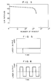
- the number of readouts by irradiating playback light of 1.0 mW continuously is shown in Fig. 1.
- a 0.5 % solution obtained by dissolving bis(triethylsiloxy)-germanium-tetra-(octyloxycarbonyl)-naphthalocyanine and copper tetra-t-butylnaphthalocyanine in a ratio of 1:0.75 in carbon tetrachloride was spin coated to form a recording layer of 43 nm thickness.
- the reflectance of the recording layer of the resulting recording medium from the substrate side was 32 %.
- output light of a laser diode of 830 nm in wavelength was focused in a spot diameter of 1.2 ⁇ m, and a signal of a recording frequency of 1 MHz was written from the substrate side at a linear speed of 8.0 m/s and an output power of 9 mW. Then, readout was conducted with playback light of 1.0 mW to give a playback C/N ratio of 50 dB.
- the number of readouts by irradiating playback light of 1.0 mW continuously is shown in Fig. 2.
- a 1.0 % solution obtained by dissolving bis(tributylsiloxy)-germanium-tetra-(octyloxycarbonyl)-naphthalocyanine in carbon tetrachloride was spin coated to form a recording layer of 53 nm.
- the reflectance of the recording layer of the resulting recording medium from the substrate side at a wavelength of 80 nm was 38 %.
- output light of a laser diode of 830 nm in wavelength was focused in a spot diameter of 1.2 ⁇ m, and a signal of a recording frequency of 1 MHz was written from the substrate side at a linear speed of 8.0 m/s and an output power of 9 mW. Then, readout was conducted with playback light of 1.0 mW to give a playback C/N ratio of 42 dB.
- the readout light stability by changing the power of playback light is shown in Fig. 3.
- the recording medium was deteriorated at a playback light power of 1.0 mW.
- a 1.0 % solution obtained by dissolving bis(tributyloxy)-silicon-tetra-(cyclohexylthio)-naphthalocyanine and zinc tetra-t-butylnaphthalocyanine in a ratio of 1:0.8 in carbon tetra-chloride was spin coated to form a recording layer of 55 nm thickness.
- the reflectance of the recording layer of the resulting recording medium from the substrate side at a wavelength of 830 nm was 37 %.
- output light of laser diode of 830 nm in wavelength was focused in a spot diameter of 1.2 ⁇ m, and a signal of a recording frequency of 1 MHz was written from the substrate side at a linear speed of 8.0 m/s and an output power of 9 mW. Then, readout was conducted with playback light of 1.0 mW to give a playback C/N ratio of 49 dB.
- the number of readouts by irradiating playback light of 1.0 mW continuously was 10 5 or more.
- a 0.8 % solution obtained by dissolving bis(tripropylsiloxy)-silicon-tetra-(cyclohexylthio)-naphthalocyanine and vanadyl tetra-t-butylnaphthalocyanine in a ratio of 1:0.8 in carbon tetrachloride was spin coated to form a recording layer of 49 nm thickness.
- the reflectance of the recording layer of the resulting recording medium from the substrate side at a wavelength of 830 nm was 35 %.
- output light of a laser diode of 830 nm in wavelength was focused in a spot diameter of 1.2 ⁇ m, and a signal of a recording frequency of 1 MHz was written from the substrate side at a linear speed of 8.0 m/s and an output power of 9 mW. Then, readout was conducted with playback light of 1.0 mW to give a playback C/N ratio of 51 dB.
- the number of readouts by irradiating playback light of 1.0 mW continuously was 10 5 or more.
- a 1.0 solution obtained by dissolving bis(tripropylsiloxy)-silicon-tetra-(cyclohexylthio)-naphthalocyanine and zinc tetra-t-butylnaphthalocyanine in a ratio as shown in Table 1 in carbon tetrachloride was spin coated to form a recording layer having a thickness as shown in Table 1.
- the reflectance of the recording layer was also examined as described in Example 1 and is shown in Table 1.
- a 1.2 % solution obtained by dissolving bis(tributylsiloxy)-silicon-tetra-(n-butylthio)-naphthalocyanine and vanadium tetra-t-butylnaphthalocyanine in a ratio of 1:0.8 in carbon tetrachloride was spin coated to form a recording layer of 52 nm thickness.
- the reflectance of the recording layer of the resulting recording medium from the substrate side at a wavelength of 830 nm was 33 %.
- output light of a laser diode of 830 nm in wavelength was focused in a spot diameter of 1.2 ⁇ m, and a signal of a recording frequency of 1 MHz was written from the substrate side at a linear speed of 8.0 m/s and an output power of 9 mW. Then, readout was conducted with playback light of 1.0 mW to give a playback C/N ratio of 46 dB.
- the number of readouts by irradiating playback light of 1.0 mW continuously was 10 5 or more.
- a 0.8% soltuion obtained by dissolving bis(tributylsiloxy)-germanium-tetra-(t-butyl)-phthalocyanine and palladium tetra-t-butylphthalocyanine in a ratio of 1:0.8 in carbon tetrachloride was spin coated to form a recording layer of 46 nm thickness.
- the reflectance of the recording layer of the resulting recording medium from the substrate side at a wavelength of 690 nm was 31%.
- output light of a laser diode of 690 nm in wavelength was focused in a spot diameter of 1.2 ⁇ m, and a signal of a recording frequency of 1 MHz was written from the substrate side at a linear speed of 8.0 m/s and an output power of 6 mW. Then, readout was conducted with playback light of 1.0 mW to give a playback C/N ratio of 43 dB.
- the number of readouts by irradiating playback light of 1.0 mW continuously was 10 5 or more.
- a 1.0 % solution obtained by dissolving bis(triethylsiloxy)-germanium-tetra-(t-butyl)-phthalocyanine and copper tetra-t-butyl-phthalocyanine in a ratio of 1:0.8 in carbon tetrachloride was spin coated to form a recording layer of 45 nm thickness.
- the reflectance of the recording layer of the resulting recording medium from the substrate side at a wavelength of 690 nm was 29 %.
- output light of a laser diode of 690 nm in wavelength was focused in a spot diameter of 1.2 ⁇ m, and a signal of a recording frequency of 1 MHz was written from the substrate side at a linear speed of 8.0 m/s and an output power of 6 mW. Then, readout was conducted with playback light of 1.0 mW to give a playback C/N ratio of 44 dB.
- the number of readouts by irradiating playback light of 1.0 mW continuously was 10 5 or more.
- a 1.0 % solution obtained by dissolving bis(triethylsiloxy)-germanium-tetra-(t-butyl)-phthalocyanine and zinc tetra-t-butyl-phthalocyanine in a ratio as shown in Table 2 in carbon tetrachloride was spin coated to form a recording layer having a thickness as shown in Table 2.
- the reflectance of the recording layer was also examined as described in Example 8 and is shown in Table 2.
- the readout light stability of the recording medium obtained in Example 1 was evaluated, while applying the laser output of readout light as shown in Fig. 5.
- the number of readouts when continuously irradiated by playback light of 1.0 mW was 10 5 or more.
- Example 10 Using the same optical system as used in Example 10, the readout light stability of the recording medium obtained in Example 1 was evaluated, while applying the laser output of readout light as shown in Fig. 6. As a result, the number of readouts when continuously irradiated by playback light of 1.0 mW was 10 5 or more.
- a recording medium was produced by vacuum depositing bis(triphenylsiloxy)-silicon-phthalocyanine at a vacuum of 6.7 x 10 -6 torr on a polycarbonate substrate of 130 mm in diameter and 1.2 mm in thickness with guiding grooves, the temperature of the substrate being not particularly controlled but allowed to stand, to give a recording layer of 80 nm thickness.
- Spectroscopic properties (reflectance and transmittance) of the resulting recording layer are shown in Fig. 7.
- the maximum absorption was 690 nm.
- output light of a laser diode of 780 nm in wavelength was focused in a spot diameter of 1.2 ⁇ m, and a signal of a recording frequency of 1 MHz was written from the substrate side at a linear speed of 8.0 m/s and an output power of 9 mW.
- the absorption rate at a wavelength of 780 nm was 4.1 %.
- readout was carried out using playback light of 1.0 mW.
- the playback C/N ratio was 46 dB.
- the number of readouts at a readout light of 1.0 mW was 10 5 or more. This means that the recording medium is excellent in readout light stability.
- a recording medium was produced by vacuum depositing bis(phenoxy)-silicon-phthalocyanine on a polycarbonate substrate of 130 nm in diameter and 1.2 mm in thickness with guiding grooves in the same manner as described in Example 12 to give a recording layer of 92 nm thickness.
- Spectroscopic properties of the resulting recording layer are shown in Fig. 8. The maximum absorption was 720 nm.
- Vanadyl-tetra-(t-butyl)-naphthalocyanine was synthesized according to the method disclosed in Zhurnal Obschei Khimii, vol. 42, p. 696 (1972).
- a 1.5 % chloroform solution of this compound was prepared and coated on a glass substrate of 1.2 mm thickness by spin coating to form a recording layer of 78 nm thickness.
- the spectroscopic properties of the recording layer of the resulting recording medium are shown in Fig. 9.
- a solution obtained by dissolving bis(tributylsiloxy)-silicon-tetra-(trimethylsilyl)-naphthalocyanine and copper tetra-t-butylnaphthalocyanine in a ratio of 1:0.8 in carbon tetrachloride was spin coated to form a recording layer of 48 nm thickness.
- the reflectance of the recording layer of the resulting recording medium from the substrate side was 37 %.
- output light of a laser diode of 830 nm in wavelength was focused in a spot diameter of 1.2 ⁇ m, and a signal of a recording frequency of 1 MHz was written from the substrate side at a linear speed of 8.0 m/s and an output power of 9 mW. Then, readout was conducted with playback light of 1.0 mW to give a playback C/N ratio of 51 dB.
- the number of readouts by irradiating playback light of 1.0 mW was 10 5 or more.
- the optical information recording medium of the present invention can be advantageously produced by spin coating or dip coating e.g. a mixture of (i) an azaphthalocyanine, phthalocyanine, or naphthalocyanine derivative and (ii) a thermal quencher on a substrate.
- the obtained thin film of the recording layer shows excellent readout light stability of 10 5 or more at a readout laser power of 0.5 to 1.5 mW. Therefore, the optical information recording medium of the present invention can suitably be used as a write-once optical recording medium.
Landscapes
- Optical Record Carriers And Manufacture Thereof (AREA)
- Thermal Transfer Or Thermal Recording In General (AREA)
Description
- This invention relates to an optical information recording medium for recording and reading out information by means of a laser beam, a process for producing the same, a readout (or playback) apparatus for optical information recording media, and a process for reading out information from these optical information recording media.
- Recently, as means for writing and reading out information in compact discs, video discs, photosensitive members for laser beam printers, optical letter readout machines, etc., optical recording media and apparatus applying a laser diode beam are practically used. For these applications an optical recording medium which absorbs a laser diode beam, that is, near infrared rays, is necessary. As the recording medium, there have been proposed recording media having an inorganic recording layer of tellurium, an alloy of tellurium, an alloy of bismuth, or the like, recording media having an organic dye-containing recording layer such as a phthalocyanine dye (US-A-4 298 995), a naphthalocyanine dye (JP-1-198391), etc.
- However, optical recording media having an inorganic recording layer (inorganic recording media) have problems in that an improvement in the productivity is difficult due to the necessity of employing a process under vacuum such as vacuum deposition, sputtering, etc. for forming a thin film on a substrate, an improvement in the recording density is limited due to a high thermal conductivity of the recording layer, and tellurium, selenium, and the like are toxic substances requiring careful handling from the viewpoint of safety and health.
- On the other hand, the recording media containing organic dyes (organic recording media) are inferior in properties such as durability and reflectance to the inorganic recording media. Further, the recording media containing organic dyes are insufficient in both durability and solubility of the dyes in a solvent. However, with such organic recording media it seems to be possible to overcome the problems of the inorganic recordng media. Thus, organic recording media having the same durability as the inorganic recording media and which can be produced by spin coating or dip coating have been studied.
- For example, there has been proposed an optical recording medium having an organic thin film of various derivatives of naphthalocyanines having Al, Ga, In, Te, Si, Ge, Sn, Pb, etc. as central metal (JP-A-1-198391).
- EP-A-279 501 discloses an optical recording medium comprising an information recording layer which contains a naphthalocyanine dye which forms a recording layer of high reflectance and withstands 106 readout cycles at a laser power of 1 mW at 830 nm. These known optical recording media do not contain a second organic dye serving as a thermal quencher.
- At present, organic recording media are used in systems wherein a playback readout power of 0.5 mW or less is used in order to reduce the damage for the organic recording medium layer. However, when a playback laser beam power of 0.5 mW or less is used, there arise various problems in that outer noises are easily introduced, no interchangeability exists for the apparatus using a playback readout power of 1 mW, and the like.
- In order to improve the readout light stability of the organic optical recording media, there has been proposed the addition of a singlet oxygen quencher to a cyanine dye (JP-A-1-21798). Such a method is effective for preventing the cyanine dye from deterioration by light but not effective for the heat energy of a laser beam of 1 mW.
- It is the object of the present invention to provide an optical information recording medium excellent in durability and reflectance of an information recording medium layer, which can be produced by spin coating, spray coating or dip coating an organic recording medium layer on a substrate, and to provide a process for producing such an optical information recording medium and the applications of such an optical information recording medium.
- The above object is achieved according to the independent claims. The dependent claims relate to preferred embodiments.
- The optical information recording medium of the present invention comprises a substrate and an information recording layer formed on the substrate, the information recording layer comprising at least two organic dyes having different chemical structures; it is
characterized in that - at least one of the organic dyes having different chemical structure is an organic dye having a pyrolysis beginning temperature of 300 °C or less and is selected from derivatives of azaphthalocyanine, phthalocyanine and naphthalocyanine, and another of the organic dyes is a thermal quencher having a pyrolysis beginning temperature of 350 °C or higher and a function for preventing thermal deterioration,
- and the information recording medium has a continuous playback or readout ability of 105 times or more at a playback laser power of 0.5 to 1.5 mW.
- According to a preferred embodiment, the information recording layer comprises (i) at least one organic dye of the formula I

- According to the present invention, this dye has a pyrolysis beginning temperature of 300°C or lower.
- According to another preferred embodiment, the thermal quencher (ii) is at least one organic dye of the formula II

- The method of the present invention for producing the optical information recording medium as defined above comprises the steps of
- (A) dissolving at least two organic dyes having different chemical structure in an organic solvent,
- (B) coating a substrate with the solution, preferably by spin coating the substrate, or by dipping the substrate in the solution and picking up the substrate therefrom, or by spray coating,
and - (C) removing the solvent; it is
- The resulting recording layer preferably has a thickness of 10 to 200 nm.
- The optical information playback or readout apparatus of the present invention comprises an optical information recording medium, an optical head equipped with a laser beam generator capable of reading out information from the optical information recording medium, rotating means for rotating the optical information recording medium, a drive circuit for controlling the operation of the optical head and the rotational speed of the rotative means, a processor for controlling the drive circuit, input means for the input of information into the processor, and output means for putting out information from the processor; it is characterized by an optical information recording medium according to the present invention as defined above.
- The apparatus preferably comprises a laser/laser beam generator emitting a laser beam having a wavelength of 640 to 720 nm or of 780 to 830 nm.
- The method of the present invention for reading out information from an optical information recording medium comprising a substrate and an information recording layer formed on the substrate comprises irradiating a laser beam on the information recording layer of the optical information recording medium, and reading out the information recorded on or in the optical information recording medium/information recording layer on the basis of the optical modulation of reflected or transmitted light; it is characterized in that an optical information recording medium of the present invention is used.
- In the following, the invention will be further explained with reference to the drawings.
- Fig. 1
- is a graph showing the readout light stability when bis(tributylsiloxy)-germanium-tetra-(octyloxy)-naphthalocyanine and copper tetra-t-butylnaphthalocyanine (mass ratio 5:4) are used as organic dyes.
- Fig. 2
- is a graph showing the readout light stability when bis(triethylsiloxy)-germanium-tetra-(octyloxy)-naphthalocyanine and copper tetra-t-butylnaphthalocyanine (mass ratio 4:3) are used as organic dyes.
- Fig. 3
- is a graph showing the readout light stability when bis(tributylsiloxy)-germanium-tetra-(octyl-oxycarbonyl)-naphthalocyanine alone is used as organic dye.
- Fig. 4
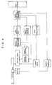
- is a schematic block diagram showing the optical system of a recording and playback apparatus.
- Fig. 5
- shows a laser output wave-form of readout light.
- Fig. 6
- shows a laser output wave-form of readout light.
- Fig. 7
- shows transmittance and reflectance spectra of a bis(triphenylsiloxy)-silicon-phthalocyanine thin film.
- Fig. 8
- shows transmittance and reflectance spectra of a bis(phenoxy)-silicon-phthalocyanine thin film.
- Fig. 9
- shows transmittance and reflectance spectra of a vanadyl-tetra-t-butyl-naphthalocyanine thin film.
- Fig. 10
- comprises cross-sectional views of one example of the optical information recording medium of the present invention.
- According to the invention, at least two organic dyes have different chemical structure. The words "different chemical structure" mean that at least one organic dye has a bulky (or top-like) structure wherein large side chains are projecting from the central atom, and at least one organic dye has a flat structure.
- The pyrolysis beginning temperature (P.B.T.) can be measured by using, for example, a differencial scanning thermobalance (e.g., TAS-100, manufactured by Rigaku Kabushiki Kaisha, JP).
- Preferred examples of compounds of formula I are:


Bis(tributylsiloxy)-germanium-tetra-(octyloxycarbonyl)-naphthalocyanine P.B.T. 203 °C Bis(tributylsiloxy)-silicon-tetra-(cyclohexylthio)-naphthalocyanine P.B.T. 298 °C Bis(tripropylsiloxy)-silicon-tetra-(cyclohexylthio)-naphthalocyanine P.B.T. 290 °C Bis(tributylsiloxy)-silicon-tetra-(n-butylthio)-naphthalocyanine P.B.T. 243 °C Bis(triethylsiloxy)-germanium-tetra-t-butyl-phthalocyanine P.B.T. 272 °C Bis(tributylsiloxy)-germanium-tetra-t-butyl-phthalocyanine P.B.T. 253 °C Bis(triphenylsiloxy)-silicon-phthalocyanine P.B.T. 292 °C Bis(phenoxy)-silicon-phthalocyanine P.B.T. 281 °C. - The content of the azaphthalocyanine derivatives, phthalocyanine derivatives and naphthalocyanine derivatives in the information recording layer is a sufficient amount for making the reflectance of the
information recording layer 20 % or more. - In order to improve the durability, it has been found that the following thermal quenchers (a) to (e) are effective for relaxing damages caused by the laser beam on the recording layer formed by using an azaphthalocyanine, a phthalocyanine or a naphthalocyanine of the formula I alone:
- (a) Crystalline dyes having a pyrolysis beginning temperature of 350 °C or higher.
- (b) Thermal quenchers having a thermal deterioration preventing effect for azaphthalocyanine, phthalocyanine and naphthalocyanine derivatives of the formula (I).
- (c) Dyes having a relaxation process for molecular excited states of azaphthalocyanine, phthalocyanine and naphthalocyanine derivatives of the formula (I).
- (d) Dyes having a large heat capacity.
- (e) Dyes having a high heat conductivity.
- By the co-use of an azaphthalocyanine, a phthalocyanine or a naphthalocyanine of the formula I and a thermal quencher of (a) to (e) mentioned above, a continuous playback (readout) ability of 105 times or more can be attained at a playback laser power of 0.5 to 1.5 mW.
- The thermal quencher can also relax a molecular excited state of the azaphthalocyamine derivatives, phthalocyanine derivatives and naphthalocyanine derivatives.
- The thermal quencher having a pyrolysis beginning temperature of 350 °C or higher and a function for preventing thermal deterioration is preferably a crystalline dye represented by the formula II,

- Preferred examples of compounds of formula II are:


Vanadyl tetra-t-butylnaphthalocyanine P.B.T. 372 °C Copper tetra-t-butylnaphthalocyanine P.B.T. 364 °C Zinc tetra-t-butylnaphthalocyanine P.B.T. 380 °C Palladium tetra-t-butylnaphthalocyanine P.B.T. 365 °C Palladium tetra-t-butylphthalocyanine P.B.T. 370 °C Copper tetra-t-butylphthalocyanine P.B.T. 386 °C Zinc tetra-t-butylphthalocyanine P.B.T. 369 °C - In order to achieve an excellent readout light stability (durability), reflectance and solubility in a solvent, the following combinations, for example, are preferred:
- A combination of


- A combination of bis(tributylsiloxy)-germanium-tetra-(octyloxycarbonyl)-naphthalocyanine and copper tetra-t-butylnaphthalocyanine.
- A combination of bis(triethylsiloxy)-germanium-tetra-(octyloxycarbonyl)-naphthalocyanine and copper tetra-t-butylnaphthalocyanine.
- A combination of bis(tributyloxy)-silicon-tetra-(cyclohexylthio)-naphthalocyanine and zinc t-butylnaphthalocyanine.
- A combination of bis(tripropyloxy)-silicon-tetra-(cyclohexylthio)-naphthalocyanine and vanadyl tetra-t-butylnaphthalocyanine.
- A combination of bis(tripropyloxy)-silicon-tetra-(cyclohexylthio)-naphthalocyanine and lead tetra-t-butylnaphthalocyanine.
- A combination of bis(tributylsiloxy)-silicon-tetra-(n-butylthio)-naphthalocyanine and palladium tetra-t-butylnaphthalocyanine.
- A combination of bis(tributylsiloxy)-germanium-tetra-(t-butyl)-phthalocyanine and palladium tetra-t-butylphthalocyanine.
- A combination of bis(triethylsiloxy)-germanium-tetra-t-butyl-phthalocyanine and copper tetra-t-butylphthalocyanine.
- A combination of bis(triethylsiloxy)-germanium-tetra-t-butyl-phthalocyanine and zinc tetra-t-butyl-phthalocyanine.
- By the combination of two or more organic dyes having different chemical structures, and specifically by the combination of (i) an organic dye having a pyrolysis beginning temperature of 300 °C or lower and selected from derivatives of azaphthalocyanine, phthalocyanine and naphthalocyanine of the formula I and (ii) a thermal quencher having a pyrolysis beginning temperature of 350 °C or higher, a readout ability of 105 times or more can be attained at a playback readout power of 0.5 to 1.5 mW.
- The organic dye having a pyrolysis beginning temperature of 300 °C or lower and selected from derivatives of azaphthalocyanine, phthalocyanine and naphthalocyanine of the formula I and the thermal quencher having a pyrolysis beginning temperature of 350 °C or higher are preferably mixed in a range of a mass ratio of the former to the latter of 1/0.01 to 1/1.5. Further, a mixing ratio so as to make the reflectance of the
information recording layer 20 % or more is preferable. - As the material for forming the substrate, there can be used thermoplastic resins and thermosetting resins such as polyvinyl chloride resins, acrylic resins, polyolefin resins, polycarbonate resins, polyvinyl acetal resins, unsaturated polyester resins, vinyl ester resins, polystyrene resins, polyether sulfone resins, polyether ether ketone resins, epoxy resins, allyl resins, polyimides, polyamide resins, etc.; inorganic polymers such as silicone resins, phosphazene resins, etc.; glass, SiO2, Si3N4, metals, etc. These material are formed into films, sheets, cylinders, prisms (trigonal or higher), etc.
- Since the substrate is subjected to repeated writing and readout of signals, it is preferable that the substrate has a light transmittance of 85 % or more and a small optical anisotropy. Depending on the material used, there can be used a structure obtained by laminating a photocurable resin on a mirror-like surface of the substrate or on a substrate surface having a guiding groove pattern (pregroove) and transcribing the guiding groove pattern on the surface of the photocurable resin layer.
- The film thickness of the information recording layer formed on the substrate is preferably in the range of 10 to 500 nm and particularly in the range of 10 to 200 nm. However, in the case of an optical information recording medium containing a compound which slightly shifts the absorption wavelength of the information recording layer against the laser wavelength, the interference effect of reflectance depending on the film thickness is large. Thus, it is preferable to use a film thickness region which makes the reflectance large. It is preferable to use a first interference film thickness of 30 to 80 nm wherein the reflectance is large and the absorption is small.
- The optical information recording medium in the form of sheet or disc of the present invention may further contain a reflective layer, a protective layer, etc., as conventionally used. Fig. 10 is a cross-sectional view showing one example of the optical informaion recording medium of the present invention comprising an information recording layer or film 1, a
substrate 2, a spacer 3, anair gap 4, aprotective film 5, and acentral hole 6. - The thus constructed optical information recording medium is exposed to a laser beam to record information by forming pits on the exposed portions by melting or sublimation. At the time of readout (or playback), the laser beam power is controlled to a predetermined weak level so as not to damage the recording layer. Thus, there takes place no thermal deformation of the pit form even if exposed to playback light 105 times or more.
- As the laser beam, there can be used various laser beams of N2, He-Ne, Ar, dye, semiconductor, lasers, etc., depending on the absorption wavelength of the information recording layer.
- For example, in the case of forming the information recording layer with a napthalocyanine mixture of formulae (I) and (II), a semiconductor laser of 780 to 830 nm can be used for recording and readout. In the case of forming the information recording layer with an azaphthalocyanine, a phthalocyanine, a naphthalocyanine or a mixture thereof, a semiconductor laser of 670 to 710 nm can be used for recording and readout. In these cases, the playback light can be used at a power level of 0.5 to 1.5 mW. Further, in the case of using an azaphthalocyanine, a naphthalocyanine or a mixture thereof, it is preferable to control the mixing ratio so as to make the reflectance of the information recording layer from the
substrate side 20 % or more. - The optical information recording medium can contain in the information recording layer a compound which can shift the maximum absorption wavelength of the information recording layer against the laser wavelength used to the shorter wavelength side by 20 to 100 nm. Further the light absorption rate of the information recording layer can preferably be in the range of 1 to 20 % of the laser beam used. The recording medium can record and read out signals by the information recording layer without further forming a reflective layer. In addition, the information recording layer preferably has a thickness in the range of making the reflectance larger by applying an interference effect of light.
- The optical information recording medium can be produced, for example, as follows.
- One process comprises dissolving an organic dye having a pyrolysis beginning temperature of 300 °C or less and selected from derivatives of azaphthalocyanine, phthalocyanine and naphthalocyanine, and a thermal quencher having a pyrolysis beginning temperature of 350 °C or higher in an organic solvent to give a solution of 0.1 to 5 % by mass, dipping a substrate in the solution, picking up the substrate, and removing the solvent to produce the desired optical information recording medium.
- Another process comprises dissolving an organic dye having a pyrolysis beginning temperature of 300 °C or less, and selected from derivatives of azaphthalocyanine, phthalocyanine and naphthalocyanine, and a thermal quencher having a pyrolysis beginning temperature of 350 °C or higher in an organic solvent to give a solution of 0.1 to 5 % by mass, applying the solution on a substrate revolving at 1000 to 5000 r.p.m. to form a film, and removing the solvent to form a recording layer of 10 to 200 nm in thickness on the substrate to produce the desired optical information recording medium.
- More concretely, two or more organic dyes for forming the information recording layer are coated on the substrate using a spin coating, spray coating or dip coating apparatus as conventionally used to form thin films. For example, an azaphthalocyanine, a phthalocyanine or a naphthalocyanine of the formula I together with a thermal quencher is dissolved in an organic solvent or dispersed in an solvent, if necessary, together with a binder, followed by coating on the substrate.
- As the binder, there can be used polymers such as polyimides, polyamides, polystyrenes, acrylic resins, silicone resins, epoxy resins, phenolic resins, etc.
- As the organic solvent, there can be used aromatic compounds such as benzene, xylene, toluene, etc.; ketones such as methyl ethyl ketone, etc.; ethers; halogenated compounds such as chloroform, carbon tetrachloride, etc.; and saturated hydrocarbons, etc., or mixtures thereof. Among them, the use of carbon tetrachloride and a mixture of methylcyclohexane and toluene is preferable.
- It has been found in connection with the present invention that the pyrolysis beginning temperatures of the azaphthalocyanines, phthalocyanines and naphthalocyanines of formula I are 300 °C or lower. On the other hand, when a semiconductor laser beam of 1 mW or more is irradiated on a recording film, the irradiated surface of the film formed with an azaphthalocyanine, a phthalocyanine, or a naphthalocyanine of the formula I alone becomes 300 °C or higher. Therefore, the recording layer obtained by using an azaphthalocyanine, a phthalocyanine or a naphthalocyanine of the formula I alone cannot withstand sufficiently a laser beam of 1 mW or more (
wavelength 830 nm), which seems to result in lowering the durability (readout light stability). - The present invention further provides a playback apparatus suitable for the optical information recording medium mentioned above.
- The present invention is illustrated by way of the following examples, in which all percent values and ratios of products are by mass unless otherwise specified.
- On a polycarbonate substrate of 1.2 nm thickness, a 0.5 % solution obtained by dissolving bis(tributylsiloxy)-germanium-tetra-(octyloxycarbonyl)-naphthalocyanine and copper tetra-t-butylnapthalocyanine in a ratio of 1:0.8 in carbon tetrachloride was spin coated to form a recording layer of 45 nm thickness. The reflectance of the recording layer of the resulting recording medium from the substrate side at a wavelength of 830 nm was 28 %.
- Further, on the recording medium, output light of a laser diode of 830 nm in wavelength was focused in a spot diameter of 1.2 µm, and a signal of a recording frequency of 1 MHz was written from the substrate side at a linear speed of 8.0 m/s and an output power of 9 mW. Then, readout was conducted with playback light of 1.0 mW to give a playback carrier-tonoise (C/N) ratio of 46 dB.
- The number of readouts by irradiating playback light of 1.0 mW continuously is shown in Fig. 1.
- On a polycarbonate substrate of 1.2 mm thickness, a 0.5 % solution obtained by dissolving bis(triethylsiloxy)-germanium-tetra-(octyloxycarbonyl)-naphthalocyanine and copper tetra-t-butylnaphthalocyanine in a ratio of 1:0.75 in carbon tetrachloride was spin coated to form a recording layer of 43 nm thickness. The reflectance of the recording layer of the resulting recording medium from the substrate side was 32 %.
- Further, on the recording medium, output light of a laser diode of 830 nm in wavelength was focused in a spot diameter of 1.2 µm, and a signal of a recording frequency of 1 MHz was written from the substrate side at a linear speed of 8.0 m/s and an output power of 9 mW. Then, readout was conducted with playback light of 1.0 mW to give a playback C/N ratio of 50 dB.
- The number of readouts by irradiating playback light of 1.0 mW continuously is shown in Fig. 2.
- On a polycarbonate substrate of 1.2 mm thickness, a 1.0 % solution obtained by dissolving bis(tributylsiloxy)-germanium-tetra-(octyloxycarbonyl)-naphthalocyanine in carbon tetrachloride was spin coated to form a recording layer of 53 nm. The reflectance of the recording layer of the resulting recording medium from the substrate side at a wavelength of 80 nm was 38 %.
- Further on the recording medium, output light of a laser diode of 830 nm in wavelength was focused in a spot diameter of 1.2 µm, and a signal of a recording frequency of 1 MHz was written from the substrate side at a linear speed of 8.0 m/s and an output power of 9 mW. Then, readout was conducted with playback light of 1.0 mW to give a playback C/N ratio of 42 dB.
- The readout light stability by changing the power of playback light is shown in Fig. 3. In this case, the recording medium was deteriorated at a playback light power of 1.0 mW.
- On a polycarbonate substrate of 1.2 mm thickness, a 1.0 % solution obtained by dissolving bis(tributyloxy)-silicon-tetra-(cyclohexylthio)-naphthalocyanine and zinc tetra-t-butylnaphthalocyanine in a ratio of 1:0.8 in carbon tetra-chloride was spin coated to form a recording layer of 55 nm thickness. The reflectance of the recording layer of the resulting recording medium from the substrate side at a wavelength of 830 nm was 37 %.
- Further, on the recording medium, output light of laser diode of 830 nm in wavelength was focused in a spot diameter of 1.2 µm, and a signal of a recording frequency of 1 MHz was written from the substrate side at a linear speed of 8.0 m/s and an output power of 9 mW. Then, readout was conducted with playback light of 1.0 mW to give a playback C/N ratio of 49 dB.
- The number of readouts by irradiating playback light of 1.0 mW continuously was 105 or more.
- On a polycarbonate substrate of 1.2 mm thickness, a 0.8 % solution obtained by dissolving bis(tripropylsiloxy)-silicon-tetra-(cyclohexylthio)-naphthalocyanine and vanadyl tetra-t-butylnaphthalocyanine in a ratio of 1:0.8 in carbon tetrachloride was spin coated to form a recording layer of 49 nm thickness. The reflectance of the recording layer of the resulting recording medium from the substrate side at a wavelength of 830 nm was 35 %.
- Further, on the recording medium, output light of a laser diode of 830 nm in wavelength was focused in a spot diameter of 1.2 µm, and a signal of a recording frequency of 1 MHz was written from the substrate side at a linear speed of 8.0 m/s and an output power of 9 mW. Then, readout was conducted with playback light of 1.0 mW to give a playback C/N ratio of 51 dB.
- The number of readouts by irradiating playback light of 1.0 mW continuously was 105 or more.
- On a polycarbonate substrate of 1.2 mm thickness a 1.0 solution obtained by dissolving bis(tripropylsiloxy)-silicon-tetra-(cyclohexylthio)-naphthalocyanine and zinc tetra-t-butylnaphthalocyanine in a ratio as shown in Table 1 in carbon tetrachloride was spin coated to form a recording layer having a thickness as shown in Table 1.
- The reflectance of the recording layer was also examined as described in Example 1 and is shown in Table 1.
- The playback C/N ratio and the number of readouts by irradiating playback light of 1.0 mW continuously were also examined in the same manner as described in Example 4 and are shown in Table 1.

- However, when the mixing ratio was more than 1:1.5, the reflectance became 20 % or less, resulting in failing to detect the playback C/N ratio and readout light stability.
- On a polycarbonate substrate of 1.2 mm thickness, a 1.2 % solution obtained by dissolving bis(tributylsiloxy)-silicon-tetra-(n-butylthio)-naphthalocyanine and vanadium tetra-t-butylnaphthalocyanine in a ratio of 1:0.8 in carbon tetrachloride was spin coated to form a recording layer of 52 nm thickness. The reflectance of the recording layer of the resulting recording medium from the substrate side at a wavelength of 830 nm was 33 %.
- Further, on the recording medium, output light of a laser diode of 830 nm in wavelength was focused in a spot diameter of 1.2 µm, and a signal of a recording frequency of 1 MHz was written from the substrate side at a linear speed of 8.0 m/s and an output power of 9 mW. Then, readout was conducted with playback light of 1.0 mW to give a playback C/N ratio of 46 dB.
- The number of readouts by irradiating playback light of 1.0 mW continuously was 105 or more.
- On a polycarbonate substrate of 1.2 mm thickness a 0.8% soltuion obtained by dissolving bis(tributylsiloxy)-germanium-tetra-(t-butyl)-phthalocyanine and palladium tetra-t-butylphthalocyanine in a ratio of 1:0.8 in carbon tetrachloride was spin coated to form a recording layer of 46 nm thickness. The reflectance of the recording layer of the resulting recording medium from the substrate side at a wavelength of 690 nm was 31%.
- Further, on the recording medium, output light of a laser diode of 690 nm in wavelength was focused in a spot diameter of 1.2 µm, and a signal of a recording frequency of 1 MHz was written from the substrate side at a linear speed of 8.0 m/s and an output power of 6 mW. Then, readout was conducted with playback light of 1.0 mW to give a playback C/N ratio of 43 dB.
- The number of readouts by irradiating playback light of 1.0 mW continuously was 105 or more.
- On a polycarbonate substrate of 1.2 mm thickness, a 1.0 % solution obtained by dissolving bis(triethylsiloxy)-germanium-tetra-(t-butyl)-phthalocyanine and copper tetra-t-butyl-phthalocyanine in a ratio of 1:0.8 in carbon tetrachloride was spin coated to form a recording layer of 45 nm thickness. The reflectance of the recording layer of the resulting recording medium from the substrate side at a wavelength of 690 nm was 29 %.
- Further, on the recording medium, output light of a laser diode of 690 nm in wavelength was focused in a spot diameter of 1.2 µm, and a signal of a recording frequency of 1 MHz was written from the substrate side at a linear speed of 8.0 m/s and an output power of 6 mW. Then, readout was conducted with playback light of 1.0 mW to give a playback C/N ratio of 44 dB.
- The number of readouts by irradiating playback light of 1.0 mW continuously was 105 or more.
- On a polycarbonate substrate of 1.2 mm thickness, a 1.0 % solution obtained by dissolving bis(triethylsiloxy)-germanium-tetra-(t-butyl)-phthalocyanine and zinc tetra-t-butyl-phthalocyanine in a ratio as shown in Table 2 in carbon tetrachloride was spin coated to form a recording layer having a thickness as shown in Table 2.
- The reflectance of the recording layer was also examined as described in Example 8 and is shown in Table 2.
- The playback C/N ratio and the number of readouts by irradiating playback light of 1.0 mW continuously were also examined in the same manner as described in Example 8 and are shown in Table 2.

- As is clear from Table 2, good playback C/N ratios and readout light stability are obtained for the individual mixing ratios.
- However, when the mixing ratio was more than 1:1.5, the reflectance became 20 % or less, resulting in failing to detect the playback C/N ratio and readout light stability.
- Using a recording playback apparatus as shown in Fig. 4, the readout light stability of the recording medium obtained in Example 1 was evaluated, while applying the laser output of readout light as shown in Fig. 5. As a result, the number of readouts when continuously irradiated by playback light of 1.0 mW was 105 or more.
- Using the same optical system as used in Example 10, the readout light stability of the recording medium obtained in Example 1 was evaluated, while applying the laser output of readout light as shown in Fig. 6. As a result, the number of readouts when continuously irradiated by playback light of 1.0 mW was 105 or more.
- A recording medium was produced by vacuum depositing bis(triphenylsiloxy)-silicon-phthalocyanine at a vacuum of 6.7 x 10⁻⁶ torr on a polycarbonate substrate of 130 mm in diameter and 1.2 mm in thickness with guiding grooves, the temperature of the substrate being not particularly controlled but allowed to stand, to give a recording layer of 80 nm thickness.
- Spectroscopic properties (reflectance and transmittance) of the resulting recording layer are shown in Fig. 7. The maximum absorption was 690 nm.
- Further, on the recording medium, output light of a laser diode of 780 nm in wavelength (difference from maximum absorption: 90 nm) was focused in a spot diameter of 1.2 µm, and a signal of a recording frequency of 1 MHz was written from the substrate side at a linear speed of 8.0 m/s and an output power of 9 mW. The absorption rate at a wavelength of 780 nm was 4.1 %. After recording, readout was carried out using playback light of 1.0 mW. The playback C/N ratio was 46 dB. The number of readouts at a readout light of 1.0 mW was 105 or more. This means that the recording medium is excellent in readout light stability.
- Further, when copper tetra-t-butylphthalocyanine was mixed with bis(triphenylsiloxy)-silicon-phthalocyanine, the resulting recording medium was improved in the readout light stability compared with the recording medium using bis(triphenylsiloxy)-silicon-phthalocyanine alone.
- Using the same recording medium as used in Example 12, output light of a laser diode of 830 nm in wavelength (difference from the maximum absorption: 140 nm) was focused in a spot diameter of 1.2 µm, and a signal of a recording frequency of 1 MHz was written from the substrate side at a linear speed of 8.0 m/s and an output power of 9 mW. However, since the absorption rate at a wavelength of 830 nm was as small as 0.8 %, there was shown no recording sensitivity.
- A recording medium was produced by vacuum depositing bis(phenoxy)-silicon-phthalocyanine on a polycarbonate substrate of 130 nm in diameter and 1.2 mm in thickness with guiding grooves in the same manner as described in Example 12 to give a recording layer of 92 nm thickness.
- Spectroscopic properties of the resulting recording layer are shown in Fig. 8. The maximum absorption was 720 nm.
- Then, output light of a semiconductor laser of 830 nm in wavelength (difference from the maximum absorption: 110 nm) was focused in a spot diameter of 1.2 µm, and a signal of a recording frequency of 1 MHz was written from the substrate side at a linear speed of 8.0 m/s and an output power of 9 mW. However, since the absorption rate at a wavelength of 830 nm was as small as 0.8 %, there was shown no recording sensitivity.
- Vanadyl-tetra-(t-butyl)-naphthalocyanine was synthesized according to the method disclosed in Zhurnal Obschei Khimii, vol. 42, p. 696 (1972).
- A 1.5 % chloroform solution of this compound was prepared and coated on a glass substrate of 1.2 mm thickness by spin coating to form a recording layer of 78 nm thickness. The spectroscopic properties of the recording layer of the resulting recording medium are shown in Fig. 9.
- Recording playback properties using a semiconductor laser of 830 nm in wavelength were tried to evaluate, but the reflectance was too small to measure the focusing and tracking. Thus, the C/N ratio could not be measured.
- On a polycarbonate substrate of 1.2 mm thickness, a solution obtained by dissolving bis(tributylsiloxy)-silicon-tetra-(trimethylsilyl)-naphthalocyanine and copper tetra-t-butylnaphthalocyanine in a ratio of 1:0.8 in carbon tetrachloride was spin coated to form a recording layer of 48 nm thickness. The reflectance of the recording layer of the resulting recording medium from the substrate side was 37 %.
- Further, on the recording medium, output light of a laser diode of 830 nm in wavelength was focused in a spot diameter of 1.2 µm, and a signal of a recording frequency of 1 MHz was written from the substrate side at a linear speed of 8.0 m/s and an output power of 9 mW. Then, readout was conducted with playback light of 1.0 mW to give a playback C/N ratio of 51 dB.
- The number of readouts by irradiating playback light of 1.0 mW was 105 or more.
- As mentioned above, the optical information recording medium of the present invention can be advantageously produced by spin coating or dip coating e.g. a mixture of (i) an azaphthalocyanine, phthalocyanine, or naphthalocyanine derivative and (ii) a thermal quencher on a substrate.
- Further, the obtained thin film of the recording layer shows excellent readout light stability of 105 or more at a readout laser power of 0.5 to 1.5 mW. Therefore, the optical information recording medium of the present invention can suitably be used as a write-once optical recording medium.
Claims (15)
- Optical information recording medium comprising a substrate and an information recording layer formed on the substrate, the information recording layer comprising at least two organic dyes having different chemical structures,
characterized in thatat least one of the organic dyes having different chemical structure is an organic dye having a pyrolysis beginning temperature of 300 °C or less and is selected from derivatives of azaphthalocyanine, phthalocyanine and naphthalocyanine, and another of the organic dyes is a thermal quencher having a pyrolysis beginning temperature of 350 °C or higher and a function for preventing thermal deterioration,and the information recording medium has a continuous playback or readout ability of 105 times or more at a playback laser power of 0.5 to 1.5 mW. - Optical information recording medium according to claim 1, characterized in that the information recording layer comprises (i) at least one organic dye of the formula I

- Optical information recording medium according to claim 2, characterized in that the content of the azaphthalocyanine derivatives, phthalocyanine derivatives and/or naphthalocyanine derivatives is sufficiently high for making the reflectance of the information recording layer 20 % or more.
- Optical information recording medium according to one of claims 1 to 3, characterized in that the thermal quencher is a substance which can relax a molecular excited state of the azaphthalocyanine derivatives, phthalocyanine derivatives and/or naphthalocyanine derivatives.
- Optical information recording medium according to one of claims 1 to 4, characterized in that the thermal quencher is a crystalline dye.
- Optical information recording medium according to one of claims 1 to 5, characterized in that it comprises as the thermal quencher (ii) at least one organic dye of the formula II

- Optical information recording medium according to one of claims 1 to 6, characterized in that the information recording layer contains a compound which can shift the maximum absorption wavelength of the information recording layer against the laser wavelength used to the shorter wavelength side by 20 to 100 nm.
- Optical information recording medium according to one of claims 1 to 7, characterized in that the light absorption of the information recording layer is in the range of 1 to 20 % of the laser beam intensity used.
- Optical information recording medium according to one of claims 1 to 8, characterized in that it does not comprise a reflective layer.
- Optical information recording medium according to one of claims 1 to 9, characterized in that the information recording layer has a thickness within a range wherein the reflectance is made larger by light interference.
- Optical information recording medium according to one of claims 1 to 10, characterized in that the organic dye (i) having a pyrolysis beginning temperature of 300 °C or less and the thermal quencher (ii) are used in a mass ratio of (i)/(ii) of 1/0.01 to 1/1.5.
- A method for producing the optical information recording medium according to one of claims 1 to 11, comprising the steps of(A) dissolving at least two organic dyes having different chemical structure in an organic solvent,(B) coating a substrate with the solution, preferably by spin coating the substrate, or by dipping the substrate in the solution and picking up the substrate therefrom, or by spray coating,
and(C) removing the solvent,characterized in that, in step A, at least one dye having a pyrolysis beginning temperature of 300 °C or less, and being selected from derivatives of azaphthalocyanine, phthalocyanine and/or naphthalocyanine, and at least one dye being a thermal quencher and having a pyrolysis beginning temperature of 350 °C or higher are used. - An information playback or readout apparatus comprising an optical information recording medium, an optical head equipped with a laser beam generator capable of reading out information from the optical information recording medium, rotating means for rotating the optical information recording medium, a drive circuit for controlling the operation of the optical head and the rotational speed of the rotating means, a processor for controlling the drive circuit, input means for inputting information into the processor, and output means for outputting information from the processor, characterized in that the optical information recording medium is a medium according to one of claims 1 to 11.
- The apparatus according to claim 13, characterized by a laser beam generator emitting a laser beam having a wavelength of 640 to 720 nm or of 780 to 830 nm.
- A method for reading out information from an optical recording medium, comprising a substrate and an information recording layer formed on the substrate, which comprises
irradiating a laser beam on the information recording layer of the optical information recording medium, and reading out the information recorded on or in the optical information recording medium by means of the optical modulation of reflected or transmitted light, characterized in that an optical information recording medium according to one of claims 1 to 11 is used.
Applications Claiming Priority (6)
| Application Number | Priority Date | Filing Date | Title |
|---|---|---|---|
| JP221817/89 | 1989-08-30 | ||
| JP22181789 | 1989-08-30 | ||
| JP314065/89 | 1989-12-02 | ||
| JP1314065A JPH03173686A (en) | 1989-12-02 | 1989-12-02 | optical information recording medium |
| JP2110069A JP2816229B2 (en) | 1990-04-27 | 1990-04-27 | Optical information recording medium, method for manufacturing the same, and apparatus using optical information recording medium |
| JP110069/89 | 1990-04-27 |
Publications (3)
| Publication Number | Publication Date |
|---|---|
| EP0418611A2 EP0418611A2 (en) | 1991-03-27 |
| EP0418611A3 EP0418611A3 (en) | 1991-06-12 |
| EP0418611B1 true EP0418611B1 (en) | 1996-12-04 |
Family
ID=27311626
Family Applications (1)
| Application Number | Title | Priority Date | Filing Date |
|---|---|---|---|
| EP90116649A Expired - Lifetime EP0418611B1 (en) | 1989-08-30 | 1990-08-30 | Optical information recording medium, method and apparatus |
Country Status (4)
| Country | Link |
|---|---|
| US (2) | US5281512A (en) |
| EP (1) | EP0418611B1 (en) |
| KR (1) | KR910005252A (en) |
| DE (1) | DE69029304T2 (en) |
Families Citing this family (12)
| Publication number | Priority date | Publication date | Assignee | Title |
|---|---|---|---|---|
| KR910005252A (en) * | 1989-08-30 | 1991-03-30 | 미다 가쓰시게 | Optical information recording medium |
| JPH07104536B2 (en) * | 1990-11-30 | 1995-11-13 | 株式会社日立製作所 | Non-linear optical element |
| JP3299347B2 (en) * | 1993-07-19 | 2002-07-08 | 株式会社リコー | Optical recording medium and method for manufacturing optical recording medium |
| US5633106A (en) * | 1994-04-08 | 1997-05-27 | Mitsui Toatsu Chemicals, Inc. | Optical recording media and a method of recording and reproducing information |
| US5648197A (en) * | 1995-01-31 | 1997-07-15 | Victor Company Of Japan, Ltd. | Optical disk |
| JP3273497B2 (en) * | 1996-12-20 | 2002-04-08 | 株式会社リコー | Optical recording medium and manufacturing method thereof |
| IT1295398B1 (en) * | 1997-09-24 | 1999-05-12 | Univ Roma | MACROCYCLIC COMPOUNDS OF PORPHYRAZINE TYPE AND THEIR METALLIC DERIVATIVES AND PROCEDURE FOR THEIR PREPARATION |
| JP2004509785A (en) * | 2000-09-21 | 2004-04-02 | バイエル アクチェンゲゼルシャフト | Optical medium containing phthalocyanine dye as light absorbing compound in information layer |
| US6896945B2 (en) | 2001-08-22 | 2005-05-24 | Bayer Aktiengesellschaft | Optical data carrier comprising a phthalocyanine dye as light-absorbent compound in the information layer |
| KR100625971B1 (en) * | 2003-10-10 | 2006-09-20 | 삼성에스디아이 주식회사 | Plasma display device with improved coupling and grounding structure of circuit board |
| EP1726009A2 (en) * | 2004-02-24 | 2006-11-29 | CIBA SPECIALTY CHEMICALS HOLDING INC. Patent Departement | Optical recording materials writable using blue lasers |
| KR100684721B1 (en) * | 2005-01-12 | 2007-02-20 | 삼성에스디아이 주식회사 | Plasma display device |
Citations (2)
| Publication number | Priority date | Publication date | Assignee | Title |
|---|---|---|---|---|
| EP0373643A2 (en) * | 1988-12-15 | 1990-06-20 | MITSUI TOATSU CHEMICALS, Inc. | Near infrared absorbers and display/recording materials prepared by using same |
| EP0376327A2 (en) * | 1988-12-29 | 1990-07-04 | Sony Corporation | Optical recording medium |
Family Cites Families (13)
| Publication number | Priority date | Publication date | Assignee | Title |
|---|---|---|---|---|
| JPS5856239A (en) * | 1981-09-28 | 1983-04-02 | Tdk Corp | Optical recording medium |
| US4529688A (en) * | 1983-10-13 | 1985-07-16 | Xerox Corporation | Infrared sensitive phthalocyanine compositions |
| JPH0739211B2 (en) * | 1985-08-06 | 1995-05-01 | 三井東圧化学株式会社 | Method of manufacturing optical recording medium |
| JPH0749231B2 (en) * | 1985-08-13 | 1995-05-31 | 三菱化学株式会社 | Optical recording body |
| US4914001A (en) * | 1986-10-20 | 1990-04-03 | Fuji Photo Film Co., Ltd. | Optical information recording medium |
| US4927735A (en) * | 1987-01-07 | 1990-05-22 | Hitachi Chemical Company, Ltd. | Novel naphthalocyanine dye, method for preparing the same, and optical information recording medium employing the same |
| FR2613111B1 (en) * | 1987-03-23 | 1994-05-06 | Toyo Boseki Kk | OPTICAL RECORDING MEDIUM |
| DE3711762A1 (en) * | 1987-04-07 | 1988-10-27 | Basf Ag | MIXED PHTHALO-NAPHTHALOCYANINE AND THIN RADIATION-SENSITIVE COATING FILMS CONTAINING THESE COMPOUNDS |
| EP0305938B1 (en) * | 1987-08-31 | 1992-11-11 | MITSUI TOATSU CHEMICALS, Inc. | Phthalocyanine compounds and utility thereof |
| JP2545558B2 (en) * | 1987-11-18 | 1996-10-23 | 東洋インキ製造株式会社 | Optical recording medium |
| US4897827A (en) * | 1987-12-12 | 1990-01-30 | U.S. Philips Corporation | Video disc player with rapid track access means |
| DE3802031A1 (en) * | 1988-01-25 | 1989-07-27 | Hoechst Ag | MULTILAYERED RECORDING MATERIAL FOR OPTICAL INFORMATION |
| KR910005252A (en) * | 1989-08-30 | 1991-03-30 | 미다 가쓰시게 | Optical information recording medium |
-
1990
- 1990-08-29 KR KR1019900013361A patent/KR910005252A/en not_active Ceased
- 1990-08-29 US US07/574,069 patent/US5281512A/en not_active Expired - Fee Related
- 1990-08-30 EP EP90116649A patent/EP0418611B1/en not_active Expired - Lifetime
- 1990-08-30 DE DE69029304T patent/DE69029304T2/en not_active Expired - Fee Related
-
1995
- 1995-05-26 US US08/450,136 patent/US5561659A/en not_active Expired - Fee Related
Patent Citations (2)
| Publication number | Priority date | Publication date | Assignee | Title |
|---|---|---|---|---|
| EP0373643A2 (en) * | 1988-12-15 | 1990-06-20 | MITSUI TOATSU CHEMICALS, Inc. | Near infrared absorbers and display/recording materials prepared by using same |
| EP0376327A2 (en) * | 1988-12-29 | 1990-07-04 | Sony Corporation | Optical recording medium |
Also Published As
| Publication number | Publication date |
|---|---|
| EP0418611A2 (en) | 1991-03-27 |
| DE69029304D1 (en) | 1997-01-16 |
| US5561659A (en) | 1996-10-01 |
| EP0418611A3 (en) | 1991-06-12 |
| KR910005252A (en) | 1991-03-30 |
| DE69029304T2 (en) | 1997-04-03 |
| US5281512A (en) | 1994-01-25 |
Similar Documents
| Publication | Publication Date | Title |
|---|---|---|
| US4298975A (en) | Optical recording medium and method of optically recording information thereon | |
| US4492750A (en) | Ablative infrared sensitive devices containing soluble naphthalocyanine dyes | |
| AU622794B2 (en) | Optical information recording medium and recording method | |
| EP0176601B1 (en) | Optical recording medium | |
| US5281512A (en) | Optical information recording medium | |
| EP0097929B1 (en) | Optical information recording medium for semiconductor laser | |
| EP0203826A2 (en) | Optical recording medium and method of recording thereon | |
| EP0511598B1 (en) | Optical recording medium | |
| EP0896327A1 (en) | Optical information recording medium and method of producing the same | |
| EP0376231A2 (en) | Optical recording media | |
| CA1183037A (en) | Recording and information record elements comprising oxoindolizine and oxoindolizinium dyes | |
| EP0083991A2 (en) | Optical type information recording medium | |
| JPH10330633A (en) | Subphthalocyanin compound and optical recording medium using the same | |
| EP0294969A2 (en) | Recording medium for optical data storage | |
| EP0204876A1 (en) | Optical data storage medium having a highly reflective organic information layer | |
| JP2585459B2 (en) | Optical information recording medium | |
| JPH07262604A (en) | Optical recording medium | |
| JP3780609B2 (en) | Phthalocyanine derivative and optical recording medium using the same | |
| JP2816229B2 (en) | Optical information recording medium, method for manufacturing the same, and apparatus using optical information recording medium | |
| JP2697770B2 (en) | Optical recording and reproduction method | |
| JP3742487B2 (en) | Optical recording medium | |
| JP3434524B2 (en) | Optical recording medium | |
| EP1313096A1 (en) | Optical recording medium | |
| JP3980092B2 (en) | Optical recording medium | |
| JP2890407B2 (en) | Optical recording medium |
Legal Events
| Date | Code | Title | Description |
|---|---|---|---|
| PUAI | Public reference made under article 153(3) epc to a published international application that has entered the european phase |
Free format text: ORIGINAL CODE: 0009012 |
|
| 17P | Request for examination filed |
Effective date: 19901206 |
|
| AK | Designated contracting states |
Kind code of ref document: A2 Designated state(s): DE FR GB IT NL |
|
| PUAL | Search report despatched |
Free format text: ORIGINAL CODE: 0009013 |
|
| AK | Designated contracting states |
Kind code of ref document: A3 Designated state(s): DE FR GB IT NL |
|
| 17Q | First examination report despatched |
Effective date: 19940309 |
|
| GRAG | Despatch of communication of intention to grant |
Free format text: ORIGINAL CODE: EPIDOS AGRA |
|
| GRAH | Despatch of communication of intention to grant a patent |
Free format text: ORIGINAL CODE: EPIDOS IGRA |
|
| GRAH | Despatch of communication of intention to grant a patent |
Free format text: ORIGINAL CODE: EPIDOS IGRA |
|
| GRAA | (expected) grant |
Free format text: ORIGINAL CODE: 0009210 |
|
| AK | Designated contracting states |
Kind code of ref document: B1 Designated state(s): DE FR GB IT NL |
|
| REF | Corresponds to: |
Ref document number: 69029304 Country of ref document: DE Date of ref document: 19970116 |
|
| ET | Fr: translation filed | ||
| ITF | It: translation for a ep patent filed | ||
| PGFP | Annual fee paid to national office [announced via postgrant information from national office to epo] |
Ref country code: FR Payment date: 19970616 Year of fee payment: 8 |
|
| PG25 | Lapsed in a contracting state [announced via postgrant information from national office to epo] |
Ref country code: GB Free format text: LAPSE BECAUSE OF NON-PAYMENT OF DUE FEES Effective date: 19970830 |
|
| PLBE | No opposition filed within time limit |
Free format text: ORIGINAL CODE: 0009261 |
|
| STAA | Information on the status of an ep patent application or granted ep patent |
Free format text: STATUS: NO OPPOSITION FILED WITHIN TIME LIMIT |
|
| 26N | No opposition filed | ||
| PG25 | Lapsed in a contracting state [announced via postgrant information from national office to epo] |
Ref country code: NL Free format text: LAPSE BECAUSE OF NON-PAYMENT OF DUE FEES Effective date: 19980301 |
|
| GBPC | Gb: european patent ceased through non-payment of renewal fee |
Effective date: 19970830 |
|
| PG25 | Lapsed in a contracting state [announced via postgrant information from national office to epo] |
Ref country code: DE Free format text: LAPSE BECAUSE OF NON-PAYMENT OF DUE FEES Effective date: 19980501 |
|
| NLV4 | Nl: lapsed or anulled due to non-payment of the annual fee |
Effective date: 19980301 |
|
| PG25 | Lapsed in a contracting state [announced via postgrant information from national office to epo] |
Ref country code: FR Free format text: LAPSE BECAUSE OF NON-PAYMENT OF DUE FEES Effective date: 19990430 |
|
| REG | Reference to a national code |
Ref country code: FR Ref legal event code: ST |
|
| PG25 | Lapsed in a contracting state [announced via postgrant information from national office to epo] |
Ref country code: IT Free format text: LAPSE BECAUSE OF NON-PAYMENT OF DUE FEES;WARNING: LAPSES OF ITALIAN PATENTS WITH EFFECTIVE DATE BEFORE 2007 MAY HAVE OCCURRED AT ANY TIME BEFORE 2007. THE CORRECT EFFECTIVE DATE MAY BE DIFFERENT FROM THE ONE RECORDED. Effective date: 20050830 |