EP0418472A1 - Mécanisme d'entraînement d'un cylindre arracheur dans une peigneuse - Google Patents
Mécanisme d'entraînement d'un cylindre arracheur dans une peigneuse Download PDFInfo
- Publication number
- EP0418472A1 EP0418472A1 EP90109769A EP90109769A EP0418472A1 EP 0418472 A1 EP0418472 A1 EP 0418472A1 EP 90109769 A EP90109769 A EP 90109769A EP 90109769 A EP90109769 A EP 90109769A EP 0418472 A1 EP0418472 A1 EP 0418472A1
- Authority
- EP
- European Patent Office
- Prior art keywords
- motion
- pin
- lever
- swing
- shaft
- Prior art date
- Legal status (The legal status is an assumption and is not a legal conclusion. Google has not performed a legal analysis and makes no representation as to the accuracy of the status listed.)
- Granted
Links
Images


Classifications
-
- D—TEXTILES; PAPER
- D01—NATURAL OR MAN-MADE THREADS OR FIBRES; SPINNING
- D01G—PRELIMINARY TREATMENT OF FIBRES, e.g. FOR SPINNING
- D01G19/00—Combing machines
- D01G19/06—Details
- D01G19/26—Driving arrangements
Definitions
- the present invention relates to a detaching roller driving mechanism for a comber, for use on a spinning machine.
- the lap combing cycle of a comber includes the steps of combing the front end of a lap gripped at the rear end thereof by a nipper by a combing cylinder, advancing the nipper to move the combed fleece to detaching rollers, and reversing the detaching rollers in synchronism with the advancement of the nipper to reverse a fleece pulled out from the lap in the preceding combing cycle so that the fleece combed in the present combing cycle overlaps the fleece combed in the preceding combing cycle, rotating the detaching rollers in the normal direction to pull off the combed fleece combed in the present combing cycle from the nipper, and combing the rear end of the fleece with a top comb.
- the detaching rollers are stopped or are rotated at a low rotating speed in the normal direction, and substantially during the second half of a full turn of the cylinder shaft, the detaching rollers are rotated in the reverse direction and in the normal direction.
- Such a reciprocating rotational motion of the detaching rollers is produced by combining a constant-speed rotative input and a variable-speed rotative input applied to a differential gear mechanism connected to the input shaft of the detaching roller unit.
- the variable-speed rotative input is applied by an input means employing a cam (Japanese Examined Patent Publication (Kokoku) No. 44-17573) or an input means employing a linkage (Japanese Examined Patent Publication (Kokoku) Nos. 43-10728 and 53-15178).
- the input means employing a cam can obtain an ideal curve of motion for piecing and pulling a fleece by properly designing the cam surface of the cam. Nevertheless, the cam groove of the cam is quickly abraded because the inertia of driving members for transmitting the motion of a cam follower to the detaching roller unit is concentrated on the line of contact of the cam follower and the cam groove when reversing and accelerating the detaching rollers, which produces the advancing and reversing motions, and the mechanism is expensive because the width and shape of the cam groove must have a precise accuracy.
- the input means employing a cam When the components of the input means employing a cam are operated at high operating speed, to improve the productivity, a large impact of the cam and the cam follower when changing the direction of rotation of the detaching rollers from the reverse direction to the normal direction generates noise and vibrations, accelerates the abrasion of the cam surface, shortens the lifetime of the machine, and deteriorates the quality of the combed slivers. Therefore, the input means employing a cam is unable to operate at a high operating speed, and the productive efficiency of a machine employing such an input means is unsatisfactory.
- a comber employing an input means using a linkage namely, a camless comber
- a linkage namely, a camless comber
- the fleece delivered by the feed roller of the nipper cannot be fully drafted because a portion A of the curve of motion shown in the drawing, in particular, can be formed only with a large radius of curvature, and severe noise and shocks are liable to be generated, the parts are abraded quickly and are liable to be damaged because the radius of curvature of a portion B of the curve of motion is small. Consequently, the quality of slivers of long fibers is unsatisfactory.
- An object of the present invention is to enable a camless comber capable of operating at a high operating speed to obtain an ideal curve of motion which is equal to that obtained by a cam comber, by providing the camless comber with a novel linkage.
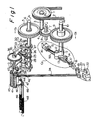
- a constant-speed rotating motion R of a drive is transmitted through a V belt 2 and a driving pulley 1 to two driving systems D1 and D2.
- the driving system D1 converts the constant-speed rotating motion into a variable-speed rotating motion by a crank mechanism C1 and a quadric crank mechanism L comprising links 26, 29 and 34, and transmits the variable-speed rotating motion through a shaft 35 to the input gear 39 of a differential gear mechanism G.
- the other driving system D2 transmits the constant-speed rotating motion R through a crank mechanism C2 to swing a swing lever 50 for a swing motion on a fixed pin 15 pivotally supporting the swing lever 50 at one end thereof.
- a connecting link 18 has one end pivotally joined to the swinging end of the swing lever 50 by a crank pin 17 and the other end pivotally jointed to the swinging end of a lever 20 pivotally supported on a joint pin 19. As shown in Fig.
- a dead point on a line passing one terminal end b19 of the locus of circular motion of the lever 20 and the pin 15 supporting the swing lever 50 is located near the terminating end of the pin 17 on the swinging end of the swing lever 50, the pin 23 on the lever 20 is connected to the planet gear unit of the differential gear mechanism is connected by connecting link, and a dead point on a line passing a position b42 of the shaft 42 of the planet gear unit farthest from the pin 21 and the pin 21 on the lever 20 is located at the terminating end of the locus of circular reciprocating motion of a joint pin 23 on the swinging end of the lever 20.
- a combined motion produced by combining the motion of the swing lever 50 in a dead zone of the swing motion and the motion of the lever 20 in a dead zone of the swing motion is transmitted to the planet gear unit of the differential gear mechanism to obtain a motion curve K having a bottom section equal to the sine curve of the original motion, and an upper section having a small radius of curvature representing a rapid reduction of the motion as shown in Fig. 5 is obtained for one cycle of operation of the swing lever 50.
- the motion curve K is combined with a curve M produced by the driving system D1 to obtain a motion curve N shown in Fig. 6.
- the motion curve N of the detaching rollers has a section B of an unchanged sine curve for a reverse feed, and a section A having an ideal curve having a small radius of curvature for completing the forward feed of the fleece.
- the length L3 of the fleece delivered during the rotation of the cylinder shaft from an angular position P0 corresponding to the start of a forward feed to an angular position P1 corresponding to the foremost position of the nipper, namely, the termination of the delivery of the fleece is longer than the length (L1 , L2) of the fleece delivered during the same period by the detaching rollers driven by the conventional detaching roller driving mechanism, so that the fleece fed by the feed roller of the nipper can be fully combed.
- a driving pulley 1 is connected to a drive, not shown, by a V belt 2.
- the pulley 1 is fixed to a driving shaft 3.
- a pinion 4 mounted on the driving shaft 3 engages a gear 5 mounted on a cylinder shaft 6 and a gear 8 mounted on an intermediate shaft 7.
- the intermediate gear 8 engages a gear 9 mounted on a crankshaft 10.
- the gears 5 and 8 have the same tooth number.
- the constant-speed rotating motion R of the driving pulley 1 is transmitted through the cylinder shaft 6 to a driving system D1 and through the crankshaft 10 to a driving system D2.
- a gear 25 and eccentric cams 31 are fixed to the cylinder shaft 6, and links 26 are supported rotatably on the cylinder shaft 6.
- a shaft 27 is supported on the free ends of the links 26.
- a gear 28 and links 29 are supported rotatably on the shaft 27.
- a pin 30 is fixed to the free ends of links 32 combined with the eccentric cams 31.
- the links 29, links 34 and a gear 33 are supported rotatably on the pin 30.
- a shaft 35 is supported for rotation in bearings, not shown, at a fixed position.
- Gears 26 and 27 are mounted fixedly on the shaft 35, and links 34 are mounted on the shaft 35 for swing motion relative to the shaft 35.
- the gears 25, 28, 33 and 36 are in continuous mesh, in that order.
- a gear 37 is in mesh with a gear 39.
- a crankshaft 10 is fixedly provided with a crank 11, and a crank pin 12 revolves around the crankshaft 10 when the crankshaft 10 is rotated.
- a block 16 is fixed to a frame, not shown, and a pin 15 is supported on the block 16.
- a swing lever 50 is supported for a swing motion on the pin 15.
- a connecting rod 13 has one end joined to the crank 11 by the crank pin 12 and the other end joined to the swing lever 50 by a joint pin 14.
- a block 22 is fixed to a frame, not shown, and supports a shaft 21.
- a lever 20 is supported pivotally on the pin 21 for a swing motion, and joint pins 19 and 23 are attached to the free ends of the lever 20.
- a connecting link 18 has one end pivotally joined to the joint pin 17 and the other end pivotally joined to the joint pin 19.
- a connecting rod 24 has one end pivotally joined to the joint pin 23 and the other end pivotally joined to the shaft 42 of a differential gear mechanism.
- the joint pins 19 and 23, and the shaft 42 reciprocate between positions b19 and d19, between positions b23 and d23, and between positions b42 and d42, respectively.
- the values of l1 and l2 are determined selectively to determine the radius of curvature of a section A of a curve of motion. For example, when the values of l1 and l2 are increased and the sizes of the related members are changed accordingly, the radius of curvature of the section A increases, and thus the curvature of the curve is reduced.
- a shaft 38 is supported for rotation in bearings, not shown, at a fixed position.
- Levers 41 are fixed to the shaft 38, and shafts 42 and 43 are supported fixedly on the levers 41.
- Gears 39 and 40 are supported rotatably on the shaft 38.
- a gear 44 is supported rotatably on the shaft 42, and the end of the connecting rod 24 is joined pivotally to the shaft 42.
- a gear 45 is supported rotatably on the shaft 43.
- Gears 39 and 44, gears 44 and 45 and gears 45 and 40 are meshed, respectively.
- the gears 39 and 45 are separated from each other.
- the gear 40 is in engagement with gears 46 and 47 fixedly mounted respectively on detaching rollers 48 and 49.
- the crankshaft 10 rotates at a rotating speed equal to that of the cylinder shaft 6 in a direction indicated by an arrow A2 (Fig. 1) opposite to that of rotation of the cylinder shaft 6.
- the joint pin 14 is reciprocated between positions a14 and d14 via positions b14, c14, d14 and e14
- the joint pin 17 is reciprocated between positions a17 and d17 via positions b17, c17, d17 and e17
- the joint pin 19 moves through positions a19, b19, c19, d19, e19, b19, a19, b19, c19 and d19, in that order
- the joint pin 23 moves according to the movement of the joint pin 19.
- the shaft is reciprocated between positions b
- the joint pin 14 moves at a relatively low speed in the vicinity of the position a14, and moves at a relatively high speed from a position after the position c14 to the position e14.
- the crank 11 is at the angular position b12, the positions b19 and b17 and the pin 15 are aligned to locate the lever 20 at the dead point thereof, and the pin 21 and the position b23 and b42 are aligned to locate the shaft 42 at the dead point thereof.
- the gear 44 is supported rotatably on the shaft 42, and the differential gear mechanism G comprises the gears 39, 44, 45 and 40. Therefore, the gear 40 is moved at a fixed speed ratio by the shaft 42 when the gear 39 is fixed, and the gears 46 and 47 is rotated by the gear 40 to rotate the detaching rollers 48 and 49.
- the surface feed distance of the detaching rollers 48 and 49 varies along a curve K (Fig. 5) during one full turn of the crank 11.
- the driving systems D1 and D2 were interlocked so that the substantially horizontal section of the curve M representing the variation of the surface feed distance of the detaching rollers 48 and 49 as driven by the driving system D1 and the substantially horizontal section of the curve K representing the variation of the surface feed distance of the detaching rollers 48 and 49 as driven by the driving system D2 coincide with each other as shown in Fig. 5 to obtain a curve N by combining the curves M and K.
Applications Claiming Priority (2)
| Application Number | Priority Date | Filing Date | Title |
|---|---|---|---|
| JP231712/89 | 1989-09-08 | ||
| JP1231712A JP2642201B2 (ja) | 1989-09-08 | 1989-09-08 | コーマに於けるデタッチングローラの駆動装置 |
Publications (2)
| Publication Number | Publication Date |
|---|---|
| EP0418472A1 true EP0418472A1 (fr) | 1991-03-27 |
| EP0418472B1 EP0418472B1 (fr) | 1994-10-19 |
Family
ID=16927831
Family Applications (1)
| Application Number | Title | Priority Date | Filing Date |
|---|---|---|---|
| EP90109769A Expired - Lifetime EP0418472B1 (fr) | 1989-09-08 | 1990-05-22 | Mécanisme d'entraînement d'un cylindre arracheur dans une peigneuse |
Country Status (4)
| Country | Link |
|---|---|
| US (1) | US5014397A (fr) |
| EP (1) | EP0418472B1 (fr) |
| JP (1) | JP2642201B2 (fr) |
| DE (1) | DE69013451T2 (fr) |
Cited By (15)
| Publication number | Priority date | Publication date | Assignee | Title |
|---|---|---|---|---|
| EP0701013A1 (fr) * | 1994-09-07 | 1996-03-13 | Maschinenfabrik Rieter Ag | Appareil de commande dans une machine de peignage |
| EP1043430A2 (fr) * | 1999-03-31 | 2000-10-11 | Maschinenfabrik Rieter Ag | Appareil d'entrainement de cylindres arracheurs d'une machine de peignage |
| CN102296386A (zh) * | 2011-08-22 | 2011-12-28 | 山西鸿基科技股份有限公司 | 棉精梳机分离罗拉间隙传动机构 |
| CN102704053A (zh) * | 2012-06-11 | 2012-10-03 | 经纬纺织机械股份有限公司 | 精梳机车尾单独试车传动机构 |
| CN102758276A (zh) * | 2012-08-09 | 2012-10-31 | 马驰 | 适用于精梳机锡林分离罗拉传动部件中的双曲柄机构 |
| CN103484982A (zh) * | 2013-09-29 | 2014-01-01 | 太仓利泰纺织厂有限公司 | 精梳机传动系统 |
| CN104195679A (zh) * | 2014-09-23 | 2014-12-10 | 中原工学院 | 一种精梳机分离罗拉变速传动机构 |
| CN104195678A (zh) * | 2014-09-23 | 2014-12-10 | 中原工学院 | 一种精梳机分离罗拉传动机构变速传动装置 |
| CN104405845A (zh) * | 2014-09-23 | 2015-03-11 | 中原工学院 | 一种曲柄导杆式精梳机分离罗拉的变速传动机构 |
| CN104520479A (zh) * | 2012-07-27 | 2015-04-15 | 马佐里机器纺织股份公司 | 调节纤维网在梳理机的分离滚筒上前进的方法及执行该方法的套件 |
| CN104195678B (zh) * | 2014-09-23 | 2017-01-04 | 中原工学院 | 一种精梳机分离罗拉传动机构变速传动装置 |
| CN109518313A (zh) * | 2019-01-25 | 2019-03-26 | 上海敦孚精梳机械有限公司 | 一种精梳机分离罗拉运动的可调装置及其调节方法 |
| EP3514272A1 (fr) * | 2018-01-23 | 2019-07-24 | Maschinenfabrik Rieter AG | Dispositif d'entraînement pour cylindres arracheurs d'une machine de peignage |
| CN110067049A (zh) * | 2018-01-23 | 2019-07-30 | 里特机械公司 | 用于精梳机的驱动设备 |
| CN110067045A (zh) * | 2018-01-23 | 2019-07-30 | 里特机械公司 | 用于精梳机的钳板组件的驱动设备 |
Families Citing this family (7)
| Publication number | Priority date | Publication date | Assignee | Title |
|---|---|---|---|---|
| IT1317208B1 (it) * | 2000-04-11 | 2003-05-27 | Vouk S P A Officine Meccanotes | Gruppo di comando per l'azionamento a passo del pellegrino deicilindri strappatori in una macchina pettinatrice |
| CN100596314C (zh) * | 2007-05-21 | 2010-03-31 | 胡平 | 精梳机分离罗拉的传动机构 |
| CN101660227B (zh) * | 2009-04-24 | 2010-12-29 | 上海一纺机械有限公司 | 一种精梳机传动的驱动结构 |
| CN102560753A (zh) * | 2010-12-16 | 2012-07-11 | 中原工学院 | 椭圆与圆柱齿轮组合式精梳机锡林的变速装置 |
| JP2014034747A (ja) * | 2012-08-09 | 2014-02-24 | Toyota Industries Corp | コーマにおけるデタッチングローラ駆動装置 |
| CN103835031A (zh) * | 2012-11-27 | 2014-06-04 | 江苏凯宫机械股份有限公司 | 棉纺精梳机锡林变速机构 |
| CN113818108B (zh) * | 2021-09-24 | 2022-09-09 | 济宁职业技术学院 | 一种基于混合驱动机构的分离罗拉驱动方法 |
Citations (3)
| Publication number | Priority date | Publication date | Assignee | Title |
|---|---|---|---|---|
| DE333103C (de) * | 1919-09-17 | 1921-02-16 | Paul August Helmbold | Antriebsvorrichtung fuer die Abreisswalze von Kaemmaschinen |
| DE1510269B1 (de) * | 1962-05-07 | 1970-04-30 | Howa Machinery Ltd | Flachkaemmaschine fuer Baumwolle |
| US3960024A (en) * | 1974-07-13 | 1976-06-01 | Kabushiki Kaisha Toyoda Jidoshokki Seisakusho | Apparatus for driving detaching rollers in textile combing machines |
Family Cites Families (3)
| Publication number | Priority date | Publication date | Assignee | Title |
|---|---|---|---|---|
| US3290731A (en) * | 1963-10-21 | 1966-12-13 | Howa Machinery Ltd | Rectilinear comber for cotton |
| DE2633351C2 (de) * | 1976-07-24 | 1983-11-17 | Hoesch Werke Ag, 4600 Dortmund | Einrichtung zum Messen der Planheit von Metallbändern |
| JPS6328918A (ja) * | 1986-07-11 | 1988-02-06 | Toyota Autom Loom Works Ltd | コ−マのデタツチングロ−ラ駆動装置 |
-
1989
- 1989-09-08 JP JP1231712A patent/JP2642201B2/ja not_active Expired - Lifetime
-
1990
- 1990-05-22 US US07/526,898 patent/US5014397A/en not_active Expired - Fee Related
- 1990-05-22 DE DE69013451T patent/DE69013451T2/de not_active Expired - Fee Related
- 1990-05-22 EP EP90109769A patent/EP0418472B1/fr not_active Expired - Lifetime
Patent Citations (3)
| Publication number | Priority date | Publication date | Assignee | Title |
|---|---|---|---|---|
| DE333103C (de) * | 1919-09-17 | 1921-02-16 | Paul August Helmbold | Antriebsvorrichtung fuer die Abreisswalze von Kaemmaschinen |
| DE1510269B1 (de) * | 1962-05-07 | 1970-04-30 | Howa Machinery Ltd | Flachkaemmaschine fuer Baumwolle |
| US3960024A (en) * | 1974-07-13 | 1976-06-01 | Kabushiki Kaisha Toyoda Jidoshokki Seisakusho | Apparatus for driving detaching rollers in textile combing machines |
Cited By (19)
| Publication number | Priority date | Publication date | Assignee | Title |
|---|---|---|---|---|
| EP0701013A1 (fr) * | 1994-09-07 | 1996-03-13 | Maschinenfabrik Rieter Ag | Appareil de commande dans une machine de peignage |
| EP1043430A2 (fr) * | 1999-03-31 | 2000-10-11 | Maschinenfabrik Rieter Ag | Appareil d'entrainement de cylindres arracheurs d'une machine de peignage |
| EP1043430A3 (fr) * | 1999-03-31 | 2001-02-21 | Maschinenfabrik Rieter Ag | Appareil d'entrainement de cylindres arracheurs d'une machine de peignage |
| CN102296386A (zh) * | 2011-08-22 | 2011-12-28 | 山西鸿基科技股份有限公司 | 棉精梳机分离罗拉间隙传动机构 |
| CN102704053A (zh) * | 2012-06-11 | 2012-10-03 | 经纬纺织机械股份有限公司 | 精梳机车尾单独试车传动机构 |
| CN104520479A (zh) * | 2012-07-27 | 2015-04-15 | 马佐里机器纺织股份公司 | 调节纤维网在梳理机的分离滚筒上前进的方法及执行该方法的套件 |
| CN102758276A (zh) * | 2012-08-09 | 2012-10-31 | 马驰 | 适用于精梳机锡林分离罗拉传动部件中的双曲柄机构 |
| CN103484982A (zh) * | 2013-09-29 | 2014-01-01 | 太仓利泰纺织厂有限公司 | 精梳机传动系统 |
| CN104195678A (zh) * | 2014-09-23 | 2014-12-10 | 中原工学院 | 一种精梳机分离罗拉传动机构变速传动装置 |
| CN104405845A (zh) * | 2014-09-23 | 2015-03-11 | 中原工学院 | 一种曲柄导杆式精梳机分离罗拉的变速传动机构 |
| CN104195679A (zh) * | 2014-09-23 | 2014-12-10 | 中原工学院 | 一种精梳机分离罗拉变速传动机构 |
| CN104195678B (zh) * | 2014-09-23 | 2017-01-04 | 中原工学院 | 一种精梳机分离罗拉传动机构变速传动装置 |
| CN104195679B (zh) * | 2014-09-23 | 2017-01-04 | 中原工学院 | 一种精梳机分离罗拉变速传动机构 |
| CN104405845B (zh) * | 2014-09-23 | 2017-02-15 | 中原工学院 | 一种曲柄导杆式精梳机分离罗拉的变速传动机构 |
| EP3514272A1 (fr) * | 2018-01-23 | 2019-07-24 | Maschinenfabrik Rieter AG | Dispositif d'entraînement pour cylindres arracheurs d'une machine de peignage |
| CN110067049A (zh) * | 2018-01-23 | 2019-07-30 | 里特机械公司 | 用于精梳机的驱动设备 |
| CN110067045A (zh) * | 2018-01-23 | 2019-07-30 | 里特机械公司 | 用于精梳机的钳板组件的驱动设备 |
| CN110067049B (zh) * | 2018-01-23 | 2022-08-30 | 里特机械公司 | 用于精梳机的驱动设备 |
| CN109518313A (zh) * | 2019-01-25 | 2019-03-26 | 上海敦孚精梳机械有限公司 | 一种精梳机分离罗拉运动的可调装置及其调节方法 |
Also Published As
| Publication number | Publication date |
|---|---|
| US5014397A (en) | 1991-05-14 |
| DE69013451T2 (de) | 1995-02-23 |
| JPH0397921A (ja) | 1991-04-23 |
| JP2642201B2 (ja) | 1997-08-20 |
| EP0418472B1 (fr) | 1994-10-19 |
| DE69013451D1 (de) | 1994-11-24 |
Similar Documents
| Publication | Publication Date | Title |
|---|---|---|
| EP0418472B1 (fr) | Mécanisme d'entraînement d'un cylindre arracheur dans une peigneuse | |
| US20070006432A1 (en) | Needling device for consolidating a fibre fleece | |
| US7373705B2 (en) | Method and an installation for needling a fibre fleece using two needle bars | |
| US3479699A (en) | Combers | |
| EP0289662A2 (fr) | Machine rotative à tresser verticalement | |
| KR0130005B1 (ko) | 코우머(comber)용 랩 니핑 장치(lap nipping mechanism)의 니퍼 프레임 요동 제어 방법 및 그 장치 | |
| US3584346A (en) | Control system for the drive of detaching rollers in textile combing machines | |
| CN1891883A (zh) | 在预针刺设备中生成绒头织物的方法以及实施该方法的装置 | |
| US5749280A (en) | Circular braiding machine with inner and outer spools arranged on circular track | |
| CN1121515C (zh) | 一种圆梳机的驱动装置 | |
| US3960024A (en) | Apparatus for driving detaching rollers in textile combing machines | |
| US3600758A (en) | Textile comber nipper drive | |
| US3604063A (en) | Textile comber detaching roll drive | |
| JP2595425B2 (ja) | かぎ針を備えたたて編機 | |
| US4166399A (en) | Drive device for the detaching rollers in combing machines | |
| US4958413A (en) | Drive mechanism for a feed roll of a combing machine | |
| US5546636A (en) | Comber machine | |
| JPH09176944A (ja) | 丸打ち組み機 | |
| EP2458045B1 (fr) | Peigne | |
| JP2857014B2 (ja) | コーマにおけるデタッチングローラの駆動装置 | |
| US3290731A (en) | Rectilinear comber for cotton | |
| CN1179075C (zh) | 精梳机分离罗拉的传动装置 | |
| US3358516A (en) | Rectilinear comber | |
| US3400431A (en) | Comber nipper feed system | |
| JPH0368132B2 (fr) |
Legal Events
| Date | Code | Title | Description |
|---|---|---|---|
| PUAI | Public reference made under article 153(3) epc to a published international application that has entered the european phase |
Free format text: ORIGINAL CODE: 0009012 |
|
| AK | Designated contracting states |
Kind code of ref document: A1 Designated state(s): CH DE IT LI |
|
| 17P | Request for examination filed |
Effective date: 19910524 |
|
| 17Q | First examination report despatched |
Effective date: 19940111 |
|
| ITF | It: translation for a ep patent filed |
Owner name: INTERPATENT ST.TECN. BREV. |
|
| GRAA | (expected) grant |
Free format text: ORIGINAL CODE: 0009210 |
|
| AK | Designated contracting states |
Kind code of ref document: B1 Designated state(s): CH DE IT LI |
|
| REF | Corresponds to: |
Ref document number: 69013451 Country of ref document: DE Date of ref document: 19941124 |
|
| PLBE | No opposition filed within time limit |
Free format text: ORIGINAL CODE: 0009261 |
|
| STAA | Information on the status of an ep patent application or granted ep patent |
Free format text: STATUS: NO OPPOSITION FILED WITHIN TIME LIMIT |
|
| 26N | No opposition filed | ||
| PGFP | Annual fee paid to national office [announced via postgrant information from national office to epo] |
Ref country code: DE Payment date: 20020503 Year of fee payment: 13 |
|
| PGFP | Annual fee paid to national office [announced via postgrant information from national office to epo] |
Ref country code: CH Payment date: 20020529 Year of fee payment: 13 |
|
| PG25 | Lapsed in a contracting state [announced via postgrant information from national office to epo] |
Ref country code: LI Free format text: LAPSE BECAUSE OF NON-PAYMENT OF DUE FEES Effective date: 20030531 Ref country code: CH Free format text: LAPSE BECAUSE OF NON-PAYMENT OF DUE FEES Effective date: 20030531 |
|
| PG25 | Lapsed in a contracting state [announced via postgrant information from national office to epo] |
Ref country code: DE Free format text: LAPSE BECAUSE OF NON-PAYMENT OF DUE FEES Effective date: 20031202 |
|
| REG | Reference to a national code |
Ref country code: CH Ref legal event code: PL |
|
| PG25 | Lapsed in a contracting state [announced via postgrant information from national office to epo] |
Ref country code: IT Free format text: LAPSE BECAUSE OF NON-PAYMENT OF DUE FEES;WARNING: LAPSES OF ITALIAN PATENTS WITH EFFECTIVE DATE BEFORE 2007 MAY HAVE OCCURRED AT ANY TIME BEFORE 2007. THE CORRECT EFFECTIVE DATE MAY BE DIFFERENT FROM THE ONE RECORDED. Effective date: 20050522 |