EP0417879A1 - Insulating support for tubing string - Google Patents
Insulating support for tubing string Download PDFInfo
- Publication number
- EP0417879A1 EP0417879A1 EP90301505A EP90301505A EP0417879A1 EP 0417879 A1 EP0417879 A1 EP 0417879A1 EP 90301505 A EP90301505 A EP 90301505A EP 90301505 A EP90301505 A EP 90301505A EP 0417879 A1 EP0417879 A1 EP 0417879A1
- Authority
- EP
- European Patent Office
- Prior art keywords
- hanger
- mandrel
- counterbore
- shoulder
- bushing
- Prior art date
- Legal status (The legal status is an assumption and is not a legal conclusion. Google has not performed a legal analysis and makes no representation as to the accuracy of the status listed.)
- Granted
Links
Images

Classifications
-
- E—FIXED CONSTRUCTIONS
- E21—EARTH DRILLING; MINING
- E21B—EARTH DRILLING, e.g. DEEP DRILLING; OBTAINING OIL, GAS, WATER, SOLUBLE OR MELTABLE MATERIALS OR A SLURRY OF MINERALS FROM WELLS
- E21B17/00—Drilling rods or pipes; Flexible drill strings; Kellies; Drill collars; Sucker rods; Cables; Casings; Tubings
- E21B17/003—Drilling rods or pipes; Flexible drill strings; Kellies; Drill collars; Sucker rods; Cables; Casings; Tubings with electrically conducting or insulating means
-
- E—FIXED CONSTRUCTIONS
- E21—EARTH DRILLING; MINING
- E21B—EARTH DRILLING, e.g. DEEP DRILLING; OBTAINING OIL, GAS, WATER, SOLUBLE OR MELTABLE MATERIALS OR A SLURRY OF MINERALS FROM WELLS
- E21B33/00—Sealing or packing boreholes or wells
- E21B33/02—Surface sealing or packing
- E21B33/03—Well heads; Setting-up thereof
- E21B33/04—Casing heads; Suspending casings or tubings in well heads
-
- E—FIXED CONSTRUCTIONS
- E21—EARTH DRILLING; MINING
- E21B—EARTH DRILLING, e.g. DEEP DRILLING; OBTAINING OIL, GAS, WATER, SOLUBLE OR MELTABLE MATERIALS OR A SLURRY OF MINERALS FROM WELLS
- E21B36/00—Heating, cooling, insulating arrangements for boreholes or wells, e.g. for use in permafrost zones
- E21B36/04—Heating, cooling, insulating arrangements for boreholes or wells, e.g. for use in permafrost zones using electrical heaters
-
- E—FIXED CONSTRUCTIONS
- E21—EARTH DRILLING; MINING
- E21B—EARTH DRILLING, e.g. DEEP DRILLING; OBTAINING OIL, GAS, WATER, SOLUBLE OR MELTABLE MATERIALS OR A SLURRY OF MINERALS FROM WELLS
- E21B2200/00—Special features related to earth drilling for obtaining oil, gas or water
- E21B2200/01—Sealings characterised by their shape
Definitions
- the present invention relates to an improved structure for supporting and sealing a tubing string or a portion of a tubing string in a well and electrically insulating the tubing string or the portion of the tubing string from the remainder of the support structure or the tubing string.
- the I. C. Looman U. S. Patent No. 2,244,256 discloses the removal of congealed paraffin and asphaltic bodies in oil wells and suggest the electrical heating of the wells.
- the tubing string hanger is insulated from the housing in which it lands by an annulus 19 of electrically insulating material preventing electric contact between the hanger and the housing.
- spaced insulators are mounted on the exterior of the tubing string and function as an insulating centralizer.
- the L. H. Rhoads U. S. Patent No. 2,597,261 discloses another similar structure in which an insulating bushing is provided between the cap at the upper end of the casing and the pipe line with additional insulating collars on the pipe line within the casing. This allows the use of an electric current passing through the pipe line to heat the paraffinic and sulphatic substances to maintain them in a free-flowing condition.
- the D. W. Blancher U. S. Patent No. 2,667,626 discloses a telemetering system in which an insulating sleeve is used to provide the electrical insulation.
- the E. T. Cugini U. S. Patent No. 4,154,302 discloses an electric cable feed-through structure and the M. G. Zavertnik U. S. Patent No. 2,896,972 discloses an insulating structure for insulating the tubular support of a hanging light fixture from the electric splice box.
- the present invention is directed to a wellhead structure directed to the use of an electrical current into the well tubing string or a portion of the tubing string to heat the paraffin and includes the well housing having an internal landing seat, a hanger having an external landing shoulder for landing on the housing landing seat, the hanger having an upper bore and a lower counterbore therethrough with a downwardly facing shoulder therebetween, a tubular hanger mandrel positioned within the hanger counterbore and having an upper annular flange extending around the upper portion of the hanger mandrel and positioned a short distance below the upper end of the hanger mandrel, a sleeve secured within the lower portion of the hanger counterbore in surrounding relationship to a portion of the hanger mandrel below said mandrel flange and having an upper supporting surface, a pair of annular insulating bushings, one of said bushings positioned between the lower surface of said mandrel flange and the sleeve support surface and the other
- An object of the present invention is to provide an improved tubing insulation structure for a wellhead to allow the use of electric heating of the well.
- Another object of the present invention is to provide an improved wellhead structure which both supports and insulates tubing from the hanger and housing.
- a further object of the present invention is to provide an improved wellhead structure for supporting and insulating the tubing in which the insulators transfer the tubing weight to the hanger and also provide for aligning the tubing with respect to the hanger.
- Still another object of the present invention is to provide an improved tubing support structure to maintain or seal pressure from the inside to the outside of a tubing string.
- Still another object of the present invention is to provide an improved insulating support structure which isolates a section of tubing string from the remainder of the tubing string.
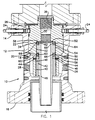
- the wellhead 10 as shown in FIGURE 1 includes the housing 12, which is in the form of a spool with flanges 14 and 16 at its upper and lower ends for connection into the wellhead stack.
- Internal landing seat 18 is formed on the interior of housing 12 and is adapted to receive landing shoulder 20 of hanger 22 as can be seen in the drawing.
- Locking pins 24 thread radially inward in upper flange 14 and are positioned to engage within groove 26 around the upper exterior of hanger 22. Suitable sealing is provided above and below groove 26 as shown.
- Ports 28 extend through housing 12 into the space between hanger 22 and the interior of housing 12 below landing seat 18.
- the exterior of housing 12 around port 28 is formed to receive a suitable fitting to provide the communication through ports 28.
- Hanger 22 includes upper bore 30 and lower counterbore 32 with downwardly facing shoulder 34 therebetween.
- the upper portion of bore 30 is threaded at 36 to receive tubular member (not shown).
- the lower end of counterbore 32 is threaded at 40 to receive support sleeve 42 and locking pins 44 thread through hanger 22 to engage within outer groove 46 in the upper portion of support sleeve 42.
- Hanger mandrel 48 is generally tubular in shape and includes radially extending annular flange 50 around its upper portion a short distance below upper end 52. As can be seen from the drawings, the outer diameter of flange 50 is less than the inner diameter of hanger counterbore 32 so that when mandrel 48 is centered within counterbore 32 the outer surface of flange 50 is spaced from the inner surface of counterbore 32.
- Annular insulating bushings 54 and 56 are positioned around the exterior of mandrel 48 immediately above and below flange 50.
- Upper bushing 54 is against the upper surface of flange 50 and has a greater thickness so that its upper surface 58 when engaged with shoulder 34 in hanger 22, upper end 52 of mandrel 48 is spaced below shoulder 34 of hanger 22.
- Lower bushing 56 is positioned between the lower surface of flange 50 and against the upper support surface 60 of support sleeve 42.
- Bushings 54 and 56 are preferably of a material which is both electri cally insulating and has sufficient strength to transfer the tubing loading to support sleeve 42 and thus to hanger 22.
- upper bushing 54 is sufficiently strong to maintain the upper end of hanger mandrel 48 centered with the upper portion of counterbore 32 under conditions of bending and vibration. It has been determined that certain ceramic materials are suitable and readily available for use for bushings 54 and 56. Other materials may be used provided it includes the physical and electrical characteristics specified above. Both bushings 54 and 56 include inner grooves 62 and outer grooves 64 in which suitable sealing means, such as elastomeric seal rings 66 and 68, are positioned to prevent leakage between hanger mandrel 48 and hanger 22. Both bushings 54 and 56 are positioned tightly around the exterior of mandrel 48 and have sufficient radial dimension to prevent engagement of mandrel 48 with the surface of counterbore 32.
- mandrel 48 is reduced in diameter immediately below bushing 56 to further ensure that it does not come into contact with support sleeve 42.
- mandrel 48 is completely electrically insulated from wellhead 10 and the other components of the assembly which are in contact therewith.
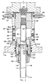
- wellhead 70 is similar to wellhead 10 and includes spool housing 72 with upper and lower flanges 74 and 76 at the upper and lower ends of housing 72 for connection into the wellhead stack.
- Internal landing seat 78 is formed on the interior of housing 72 and is adapted to receive landing shoulder 80 of hanger 82.
- Locking pins 84 thread radially inward in upper flange 74 and are positioned to engage within groove 86 around the upper exterior of hanger 82. Suitable sealing is provided above and below groove 86.
- Ports 88 extend through housing 72 and are similar to ports 28.
- Hanger 82 is generally tubular in shape and includes central bore 90 threaded at the upper end thereof at 92 and threaded at the lower end thereof at 94 for receiving tubing sub 96.
- Tubing sub 96 extends downward from the lower end of hanger bore 90 and engages within the upper threaded bore 98 of hanger mandrel 100.
- Hanger mandrel 100 includes intermediate bore 102 below bore 98 with shoulder 104 therebetween and lower threaded bore 106.
- Tubing mandrel 108 is generally tubular in shape having a central bore 110 and an outer flange 112 spaced below upper end 114 of tubing mandrel 108.
- the lower exterior end 116 of tubing mandrel 108 is threaded to receive the upper end of a tubing string (not shown) which is to be supported thereon.
- Support sleeve 118 is threaded in lower threaded bore 106 of mandrel 100 and is secured in position by locking pins 120 which thread through the lower portion of hanger mandrel 100 and engage support sleeve 118.
- Annular insulating bushings 122 and 124 are positioned around the exterior of mandrel 108 immediately above and below flange 112.
- Upper bushing 122 is against the upper surface of flange 112 and has a greater thickness than the height of the upper end 114 of tubing mandrel 108 above flange 112 so that its upper surface 126 when engaged with shoulder 104 in hanger mandrel 100, upper end 114 of tubing mandrel 108 is spaced below shoulder 103 of hanger mandrel 100.
- Lower bushing 124 is positioned between the lower surface of flange 112 and against the upper support surface 128 of support sleeve 118.
- Bushings 122 and 124 are similar in material and strength characteristics to bushings 54 and 56 as previously discussed and include suitable seals as hereinafter discussed.
- Seal 130 is provided around the upper exterior of bushing 122 and seal 132 is provided around the lower interior of bushing 122.
- Seal 134 is provided around the upper interior of bushing 124 and seal 136 is provided around the lower exterior of bushing 124.
- Each of the seals 130, 132, 134 and 136 include a metallic spacer ring 138 at the corners of the bushings and a cup shaped ring near the mid points of the bushings with the open end of the cups of bushing 122 facing upwardly and the open end of the cups of bushing 124 facing downwardly.
- Both bushings 122 and 124 fit closely around the exterior of tubing mandrel 105 and extend outwardly beyond the exterior of flange 112 to ensure that tubing mandrel flange 112 does not come into contact with the interior of intermediate bore 102 of hanger mandrel 100. In this manner bushings 122 and 124 completely insulate tubing mandrel 108 and the tubing suspended therefrom from being in contact with the wellhead 70 or other components which are in contact therewith. The exterior of tubing mandrel 108 is reduced in diameter immediately below bushing 124 to further ensure that it does not come into contact with support sleeve 118.
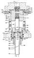
- wellhead 150 is similar to wellhead 70 and includes a spool housing 152 with upper and lower flanges 154 and 156 for connection into the wellhead stack.
- Internal landing seat 158 is formed on the interior of housing 152 and is adapted to receive landing shoulder 160 of hanger 162 landed thereon as shown in FIGURE 3.
- Locking pins 164 thread radially inward in upper flange 154 and are positioned to engage within groove 166 around the upper exterior of hanger 162. Suitable sealing is provided above and below groove 166 as shown.
- Ports 168 extend through housing 152 into the space between hanger 162 and the interior of housing 152 below landing seat 158.
- Hanger 162 is generally tubular in shape and includes central bore 170 threaded at the upper end thereof at 172 for receiving at tubular member therein and threaded at the lower end thereof at 174 for receiving tubing sub 176.
- Tubing sub 176 extends downward from the lower end of hanger bore 170 and engages within the upper threaded bore 178 of hanger mandrel 180.
- Hanger mandrel 180 includes intermediate bore 182 below bore 178 with shoulder 184 therebetween and lower threaded bore 186.
- Tubing mandrel 188 is generally tubular in shape having a central bore 190 and an outer flange 192 spaced below upper end 196 of tubing mandrel 188.
- tubing mandrel 188 The lower exterior end 196 of tubing mandrel 188 is threaded to receive the upper end of a tubing string (not shown) which is to be supported thereon.
- Support sleeve 198 is threaded in lower threaded bore 186 of mandrel 180 and is secured in position by locking pins 200 which extend through the lower portion of hanger mandrel 180 and engage support sleeve 198.
- Annular insulating bushings 202 and 204 are positioned around the exterior of mandrel 180 immediately above and below flange 192.
- Upper bushing 202 is against the upper surface of flange 192 and has a greater thickness than the height of the upper end 194 of tubing mandrel 180 above flange 192 so that its upper surface 206 when engaged with shoulder 184 in hanger mandrel 180, upper end 194 of tubing mandrel 188 is spaced below shoulder 184 of hanger mandrel 180.
- Lower bushing 204 is positioned between the lower surface of flange 192 and against the upper support surface 206 of support sleeve 198.
- Bushings 202 and 204 are similar in material and strength characteristics to bushings 54, 56, 122 and 124 as previously discussed and include suitable seals as hereinafter discussed.
- the sealing means used with bushings 202 and 204 are identical with the sealing means used with bushings 54 and 56. Both bushings 202 and 204 include inner grooves 208 and outer grooves 210 in which suitable sealing means, *such as elastomeric seal rings 212 and 214, are positioned to prevent leakage between the interior of hanger mandrel 180 and tubing mandrel 188.
- suitable sealing means such as elastomeric seal rings 212 and 214
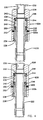
- FIGURE 4 is a sectional view of the electrical insulation of section 220 of tubing string from the remainder of string 222 through the use of two insulating couplings 224 and 226 which connect section 220 at its upper and lower end respectively to tubing string 222.
- Couplings 224 and 226 are identical and are given the same component numerical identification.
- Couplings 224 and 226 include coupling body 228 which has upper internal threads 230, first counterbore 232 below threads 230 with shoulder 234 formed therebetween and second counterbore 236 which is threaded to receive support sleeve 238.
- the portions 220a and 220b of tubing string 222 and section 220 include an external flange 240 immediivelyately below upper end 242 thereof with upwardly facing shoulder 244 spaced below upper end 242 by a distance which is less than the thickness of insulating ring 246 and downwardly facing shoulder 248.
- the lower exterior surface 250 below shoulder 248 is maintained substantial cylindrical for the distance approximating the thickness of insulating ring 252 which engages shoulder 248 and is reduced in diameter below surface 250 to avoid incidental contact with support sleeve 238.
- Pins 254 are threaded through body 228 and engage support sleeve 238 to secure it in position once it has been properly tightened against insulating ring 252.
- Insulating rings 246 and 252 are of a suitable construction and material to provide the desired electrical insulation and to have sufficient strength to maintain the portions within the coupling bodies 224 and 226 in their desired position and to transfer the load of the weight of the tubing string 222 to the upper string so that it can be supported from above with the string in tension. Insulating rings 246 and 252 are shown to have the same design as that of insulating bushings 122 and 124 but may be similar to insulating bushings 54 and 56.
Abstract
Description
- The present invention relates to an improved structure for supporting and sealing a tubing string or a portion of a tubing string in a well and electrically insulating the tubing string or the portion of the tubing string from the remainder of the support structure or the tubing string.
- In the production of oil and gas from wells, paraffin problems often appear. In treating such problems so that the paraffin does not build up sufficiently to create a restriction to the production the heating of the production string has commonly been attempted.
- The I. C. Looman U. S. Patent No. 2,244,256 discloses the removal of congealed paraffin and asphaltic bodies in oil wells and suggest the electrical heating of the wells. In this structure the tubing string hanger is insulated from the housing in which it lands by an annulus 19 of electrically insulating material preventing electric contact between the hanger and the housing. Additionally spaced insulators are mounted on the exterior of the tubing string and function as an insulating centralizer.
- The L. H. Rhoads U. S. Patent No. 2,597,261 discloses another similar structure in which an insulating bushing is provided between the cap at the upper end of the casing and the pipe line with additional insulating collars on the pipe line within the casing. This allows the use of an electric current passing through the pipe line to heat the paraffinic and sulphatic substances to maintain them in a free-flowing condition.
- The C. A. Carpenter U. S. Patent No. 2,728,396, the W. G. Green U. S. Patent No. 2,982,354, the J. P Brusco U. S. Patent No. 2,812,818, the T. C. Dauphine U. S. Patent No. 4,487,257 and B. J. Eastlund et al U. S. Patent No. 4,716,960 all disclose similar insulating structures for the use of an electric current to maintain the well fluids in a free-flowing condition to allow maximum production.
- The D. W. Blancher U. S. Patent No. 2,667,626 discloses a telemetering system in which an insulating sleeve is used to provide the electrical insulation.
- The E. T. Cugini U. S. Patent No. 4,154,302 discloses an electric cable feed-through structure and the M. G. Zavertnik U. S. Patent No. 2,896,972 discloses an insulating structure for insulating the tubular support of a hanging light fixture from the electric splice box.
- The present invention is directed to a wellhead structure directed to the use of an electrical current into the well tubing string or a portion of the tubing string to heat the paraffin and includes the well housing having an internal landing seat, a hanger having an external landing shoulder for landing on the housing landing seat, the hanger having an upper bore and a lower counterbore therethrough with a downwardly facing shoulder therebetween, a tubular hanger mandrel positioned within the hanger counterbore and having an upper annular flange extending around the upper portion of the hanger mandrel and positioned a short distance below the upper end of the hanger mandrel, a sleeve secured within the lower portion of the hanger counterbore in surrounding relationship to a portion of the hanger mandrel below said mandrel flange and having an upper supporting surface, a pair of annular insulating bushings, one of said bushings positioned between the lower surface of said mandrel flange and the sleeve support surface and the other bushing positioned around the upper portion of said mandrel above said hanger flange and extending upwardly beyond the upper end of the hanger mandrel, and sealing means associated with said bushings to provide a seal between said mandrel and said hanger.
- An object of the present invention is to provide an improved tubing insulation structure for a wellhead to allow the use of electric heating of the well.
- Another object of the present invention is to provide an improved wellhead structure which both supports and insulates tubing from the hanger and housing.
- A further object of the present invention is to provide an improved wellhead structure for supporting and insulating the tubing in which the insulators transfer the tubing weight to the hanger and also provide for aligning the tubing with respect to the hanger.
- Still another object of the present invention is to provide an improved tubing support structure to maintain or seal pressure from the inside to the outside of a tubing string.
- Still another object of the present invention is to provide an improved insulating support structure which isolates a section of tubing string from the remainder of the tubing string.
- These and other objects of the present invention are hereinafter described and explained with reference to the drawings wherein:
- FIGURE 1 is a transverse sectional view of the improved wellhead structure of the present invention.
- FIGURE 2 is a similar sectional view of a modified form of the present invention.
- FIGURE 3 is another similar sectional view of another modified form of the present invention.
- FIGURE 4 is a sectional view of another modified form of the invention in which a section of a tubing string is insulated from the remainder of the string.
- The
wellhead 10 as shown in FIGURE 1 includes thehousing 12, which is in the form of a spool withflanges Internal landing seat 18 is formed on the interior ofhousing 12 and is adapted to receivelanding shoulder 20 ofhanger 22 as can be seen in the drawing. Lockingpins 24 thread radially inward inupper flange 14 and are positioned to engage withingroove 26 around the upper exterior ofhanger 22. Suitable sealing is provided above and belowgroove 26 as shown.Ports 28 extend throughhousing 12 into the space betweenhanger 22 and the interior ofhousing 12 belowlanding seat 18. The exterior ofhousing 12 aroundport 28 is formed to receive a suitable fitting to provide the communication throughports 28. -
Hanger 22 includesupper bore 30 andlower counterbore 32 with downwardly facingshoulder 34 therebetween. The upper portion ofbore 30 is threaded at 36 to receive tubular member (not shown). The lower end ofcounterbore 32 is threaded at 40 to receivesupport sleeve 42 and lockingpins 44 thread throughhanger 22 to engage withinouter groove 46 in the upper portion ofsupport sleeve 42. -
Hanger mandrel 48 is generally tubular in shape and includes radially extendingannular flange 50 around its upper portion a short distance belowupper end 52. As can be seen from the drawings, the outer diameter offlange 50 is less than the inner diameter ofhanger counterbore 32 so that whenmandrel 48 is centered withincounterbore 32 the outer surface offlange 50 is spaced from the inner surface ofcounterbore 32. - Annular
insulating bushings mandrel 48 immediately above and belowflange 50.Upper bushing 54 is against the upper surface offlange 50 and has a greater thickness so that itsupper surface 58 when engaged withshoulder 34 inhanger 22,upper end 52 ofmandrel 48 is spaced belowshoulder 34 ofhanger 22.Lower bushing 56 is positioned between the lower surface offlange 50 and against theupper support surface 60 ofsupport sleeve 42.Bushings sleeve 42 and thus to hanger 22. Also,upper bushing 54 is sufficiently strong to maintain the upper end ofhanger mandrel 48 centered with the upper portion ofcounterbore 32 under conditions of bending and vibration. It has been determined that certain ceramic materials are suitable and readily available for use forbushings bushings inner grooves 62 andouter grooves 64 in which suitable sealing means, such aselastomeric seal rings hanger mandrel 48 andhanger 22. Bothbushings mandrel 48 and have sufficient radial dimension to prevent engagement ofmandrel 48 with the surface ofcounterbore 32. The exterior ofmandrel 48 is reduced in diameter immediately below bushing 56 to further ensure that it does not come into contact withsupport sleeve 42. Thusmandrel 48 is completely electrically insulated fromwellhead 10 and the other components of the assembly which are in contact therewith. - In a modified form of the invention illustrated in FIGURE 2,
wellhead 70 is similar towellhead 10 and includesspool housing 72 with upper andlower flanges housing 72 for connection into the wellhead stack.Internal landing seat 78 is formed on the interior ofhousing 72 and is adapted to receivelanding shoulder 80 ofhanger 82. Lockingpins 84 thread radially inward inupper flange 74 and are positioned to engage withingroove 86 around the upper exterior ofhanger 82. Suitable sealing is provided above and belowgroove 86.Ports 88 extend throughhousing 72 and are similar toports 28. -
Hanger 82 is generally tubular in shape and includescentral bore 90 threaded at the upper end thereof at 92 and threaded at the lower end thereof at 94 for receivingtubing sub 96.Tubing sub 96 extends downward from the lower end of hanger bore 90 and engages within the upper threadedbore 98 ofhanger mandrel 100. -
Hanger mandrel 100 includesintermediate bore 102 belowbore 98 with shoulder 104 therebetween and lower threadedbore 106.Tubing mandrel 108 is generally tubular in shape having acentral bore 110 and anouter flange 112 spaced belowupper end 114 oftubing mandrel 108. The lowerexterior end 116 oftubing mandrel 108 is threaded to receive the upper end of a tubing string (not shown) which is to be supported thereon.Support sleeve 118 is threaded in lower threadedbore 106 ofmandrel 100 and is secured in position by lockingpins 120 which thread through the lower portion ofhanger mandrel 100 and engagesupport sleeve 118. - Annular insulating
bushings mandrel 108 immediately above and belowflange 112.Upper bushing 122 is against the upper surface offlange 112 and has a greater thickness than the height of theupper end 114 oftubing mandrel 108 aboveflange 112 so that its upper surface 126 when engaged with shoulder 104 inhanger mandrel 100,upper end 114 oftubing mandrel 108 is spaced below shoulder 103 ofhanger mandrel 100.Lower bushing 124 is positioned between the lower surface offlange 112 and against theupper support surface 128 ofsupport sleeve 118.Bushings bushings bushing 122 and seal 132 is provided around the lower interior ofbushing 122.Seal 134 is provided around the upper interior ofbushing 124 and seal 136 is provided around the lower exterior ofbushing 124. Each of theseals metallic spacer ring 138 at the corners of the bushings and a cup shaped ring near the mid points of the bushings with the open end of the cups ofbushing 122 facing upwardly and the open end of the cups ofbushing 124 facing downwardly. - Both
bushings flange 112 to ensure thattubing mandrel flange 112 does not come into contact with the interior ofintermediate bore 102 ofhanger mandrel 100. In this manner bushings 122 and 124 completely insulatetubing mandrel 108 and the tubing suspended therefrom from being in contact with thewellhead 70 or other components which are in contact therewith. The exterior oftubing mandrel 108 is reduced in diameter immediately below bushing 124 to further ensure that it does not come into contact withsupport sleeve 118. - In the modified form of the invention illustrated in FIGURE 3,
wellhead 150 is similar towellhead 70 and includes aspool housing 152 with upper andlower flanges Internal landing seat 158 is formed on the interior ofhousing 152 and is adapted to receivelanding shoulder 160 of hanger 162 landed thereon as shown in FIGURE 3. Locking pins 164 thread radially inward inupper flange 154 and are positioned to engage withingroove 166 around the upper exterior of hanger 162. Suitable sealing is provided above and belowgroove 166 as shown.Ports 168 extend throughhousing 152 into the space between hanger 162 and the interior ofhousing 152 below landingseat 158. - Hanger 162 is generally tubular in shape and includes
central bore 170 threaded at the upper end thereof at 172 for receiving at tubular member therein and threaded at the lower end thereof at 174 for receiving tubing sub 176. Tubing sub 176 extends downward from the lower end of hanger bore 170 and engages within the upper threaded bore 178 ofhanger mandrel 180.Hanger mandrel 180 includesintermediate bore 182 belowbore 178 withshoulder 184 therebetween and lower threadedbore 186.Tubing mandrel 188 is generally tubular in shape having acentral bore 190 and anouter flange 192 spaced belowupper end 196 oftubing mandrel 188. The lowerexterior end 196 oftubing mandrel 188 is threaded to receive the upper end of a tubing string (not shown) which is to be supported thereon.Support sleeve 198 is threaded in lower threadedbore 186 ofmandrel 180 and is secured in position by lockingpins 200 which extend through the lower portion ofhanger mandrel 180 and engagesupport sleeve 198. Annular insulatingbushings mandrel 180 immediately above and belowflange 192.Upper bushing 202 is against the upper surface offlange 192 and has a greater thickness than the height of theupper end 194 oftubing mandrel 180 aboveflange 192 so that itsupper surface 206 when engaged withshoulder 184 inhanger mandrel 180,upper end 194 oftubing mandrel 188 is spaced belowshoulder 184 ofhanger mandrel 180.Lower bushing 204 is positioned between the lower surface offlange 192 and against theupper support surface 206 ofsupport sleeve 198.Bushings bushings - The sealing means used with
bushings bushings bushings inner grooves 208 andouter grooves 210 in which suitable sealing means, *such as elastomeric seal rings 212 and 214, are positioned to prevent leakage between the interior ofhanger mandrel 180 andtubing mandrel 188. The structure of thewellhead 150 shown in FIGURE 3 is similar to the structure ofwellhead 70 shown in FIGURE 2 except that the sealing means used inwellhead 150 is similar to the sealing means used inwellhead 10. - The structure illustrated in FIGURE 4 is a sectional view of the electrical insulation of
section 220 of tubing string from the remainder ofstring 222 through the use of two insulatingcouplings section 220 at its upper and lower end respectively totubing string 222.Couplings Couplings coupling body 228 which has upperinternal threads 230,first counterbore 232 belowthreads 230 withshoulder 234 formed therebetween andsecond counterbore 236 which is threaded to receivesupport sleeve 238. Theportions tubing string 222 andsection 220 include anexternal flange 240 immediately belowupper end 242 thereof with upwardly facingshoulder 244 spaced belowupper end 242 by a distance which is less than the thickness of insulatingring 246 and downwardly facingshoulder 248. Thelower exterior surface 250 belowshoulder 248 is maintained substantial cylindrical for the distance approximating the thickness of insulatingring 252 which engagesshoulder 248 and is reduced in diameter belowsurface 250 to avoid incidental contact withsupport sleeve 238. Pins 254 are threaded throughbody 228 and engagesupport sleeve 238 to secure it in position once it has been properly tightened against insulatingring 252. - As can be seen, this structure allows
section 220 to be completely electrically insulated from the remainder ofstring 222 so that any electrical operation can be completed without fear of the electrical connections being shorted intotubing string 222. Insulatingrings coupling bodies tubing string 222 to the upper string so that it can be supported from above with the string in tension. Insulatingrings bushings bushings
Claims (15)
Priority Applications (1)
| Application Number | Priority Date | Filing Date | Title |
|---|---|---|---|
| AT90301505T ATE104013T1 (en) | 1989-08-07 | 1990-02-13 | ISOLATED SUSPENSION FOR A RISER LINE. |
Applications Claiming Priority (2)
| Application Number | Priority Date | Filing Date | Title |
|---|---|---|---|
| US373093 | 1989-08-07 | ||
| US07/373,093 US4923006A (en) | 1989-08-07 | 1989-08-07 | Insulating support for tubing string |
Publications (2)
| Publication Number | Publication Date |
|---|---|
| EP0417879A1 true EP0417879A1 (en) | 1991-03-20 |
| EP0417879B1 EP0417879B1 (en) | 1994-04-06 |
Family
ID=23470912
Family Applications (1)
| Application Number | Title | Priority Date | Filing Date |
|---|---|---|---|
| EP90301505A Expired - Lifetime EP0417879B1 (en) | 1989-08-07 | 1990-02-13 | Insulating support for tubing string |
Country Status (8)
| Country | Link |
|---|---|
| US (1) | US4923006A (en) |
| EP (1) | EP0417879B1 (en) |
| JP (1) | JPH0369893A (en) |
| AT (1) | ATE104013T1 (en) |
| BR (1) | BR9000829A (en) |
| CA (1) | CA2010533A1 (en) |
| DE (1) | DE69007916T2 (en) |
| NO (1) | NO900827L (en) |
Cited By (2)
| Publication number | Priority date | Publication date | Assignee | Title |
|---|---|---|---|---|
| WO2006082407A1 (en) * | 2005-02-04 | 2006-08-10 | Petrowell Limited | Wellhead assembly and method |
| CN103233712A (en) * | 2013-05-09 | 2013-08-07 | 谢伟 | Multifunctional thermal recovery device for heavy oil well |
Families Citing this family (18)
| Publication number | Priority date | Publication date | Assignee | Title |
|---|---|---|---|---|
| US5363789A (en) * | 1993-09-15 | 1994-11-15 | Single Buoy Moorings Inc. | Disconnectable mooring system |
| US5611398A (en) * | 1995-09-26 | 1997-03-18 | Duhn Industries | Two-piece drilling flange |
| US6012519A (en) * | 1998-02-09 | 2000-01-11 | Erc Industries, Inc. | Full bore tubing hanger system |
| US6199914B1 (en) | 1998-06-09 | 2001-03-13 | Duhn Oil Tool, Inc. | Drilling quick connectors |
| US6763882B2 (en) * | 2002-11-07 | 2004-07-20 | Seaboard International, Inc. | Insulated casing and tubing hangers |
| CA2415631A1 (en) * | 2003-01-03 | 2004-07-03 | L. Murray Dallas | Backpressure adapter pin and method of use |
| US6938696B2 (en) * | 2003-01-06 | 2005-09-06 | H W Ces International | Backpressure adapter pin and methods of use |
| CA2434801C (en) * | 2003-07-09 | 2005-07-26 | Bob Mcguire | Adapters for double-locking casing mandrel and method of using same |
| US7552762B2 (en) * | 2003-08-05 | 2009-06-30 | Stream-Flo Industries Ltd. | Method and apparatus to provide electrical connection in a wellhead for a downhole electrical device |
| US7410002B2 (en) * | 2003-08-05 | 2008-08-12 | Stream-Flo Industries, Ltd. | Method and apparatus to provide electrical connection in a wellhead for a downhole electrical device |
| US8844898B2 (en) | 2009-03-31 | 2014-09-30 | National Oilwell Varco, L.P. | Blowout preventer with ram socketing |
| US8544538B2 (en) | 2010-07-19 | 2013-10-01 | National Oilwell Varco, L.P. | System and method for sealing a wellbore |
| US8540017B2 (en) | 2010-07-19 | 2013-09-24 | National Oilwell Varco, L.P. | Method and system for sealing a wellbore |
| EP2683912B1 (en) | 2011-03-09 | 2017-08-23 | National Oilwell Varco, L.P. | Method and apparatus for sealing a wellbore |
| US9057239B2 (en) * | 2011-08-22 | 2015-06-16 | James L. Young | Method and apparatus for securing a lubricator and other equipment in a well |
| US10605032B2 (en) * | 2016-07-08 | 2020-03-31 | Ge Oil & Gas Pressure Control Lp | Electrically insulated tubing hanger system |
| US10502016B2 (en) * | 2017-04-24 | 2019-12-10 | Cameron International Corporation | Hanger landing pin indicator |
| WO2018204542A1 (en) * | 2017-05-03 | 2018-11-08 | Baker Hughes, A Ge Company, Llc | Hanger assembly with penetrators |
Citations (3)
| Publication number | Priority date | Publication date | Assignee | Title |
|---|---|---|---|---|
| US1825774A (en) * | 1927-11-21 | 1931-10-06 | Boynton Alexander | Casing head |
| US2982354A (en) * | 1957-04-26 | 1961-05-02 | Thomas D Copeland Jr | Paraffin removing device |
| US4411457A (en) * | 1980-04-14 | 1983-10-25 | Mitsubishi Denki Kabushiki Kaisha | Insulated pipe joint |
Family Cites Families (12)
| Publication number | Priority date | Publication date | Assignee | Title |
|---|---|---|---|---|
| US2244256A (en) * | 1939-12-16 | 1941-06-03 | Electrical Treating Company | Apparatus for clearing wells |
| US2597261A (en) * | 1949-12-09 | 1952-05-20 | Lloyd W Feller | Well clearing apparatus |
| US2667626A (en) * | 1950-01-23 | 1954-01-26 | Bendix Aviat Corp | Telemetering system for wells |
| US2728396A (en) * | 1951-11-13 | 1955-12-27 | Union Oil Co | Well heating apparatus |
| US2812818A (en) * | 1956-10-26 | 1957-11-12 | John P Brusco | Oil well sucker rod assembly |
| US2896972A (en) * | 1957-05-08 | 1959-07-28 | Killark Electric Mfg Co | Fixture hangers |
| US3294169A (en) * | 1962-12-17 | 1966-12-27 | Union Oil Co | Method and apparatus for controlling well fluids |
| US4487257A (en) * | 1976-06-17 | 1984-12-11 | Raytheon Company | Apparatus and method for production of organic products from kerogen |
| US4154302A (en) * | 1977-10-31 | 1979-05-15 | Shafco Industries, Inc. | Cable feed-through method and apparatus for well head constructions |
| US4627489A (en) * | 1984-11-13 | 1986-12-09 | Midway Fishing Tool Co. | Top entry electrical transmission safety assembly for submersible pumping |
| US4804045A (en) * | 1986-11-06 | 1989-02-14 | Reed Lehman T | Oil and gas well diversionary spool assembly |
| US4716969A (en) * | 1987-01-12 | 1988-01-05 | Camco, Incorporated | Hydraulic valve actuating means for subsurface safety valve |
-
1989
- 1989-08-07 US US07/373,093 patent/US4923006A/en not_active Expired - Lifetime
-
1990
- 1990-02-13 DE DE69007916T patent/DE69007916T2/en not_active Expired - Fee Related
- 1990-02-13 EP EP90301505A patent/EP0417879B1/en not_active Expired - Lifetime
- 1990-02-13 AT AT90301505T patent/ATE104013T1/en not_active IP Right Cessation
- 1990-02-21 BR BR909000829A patent/BR9000829A/en not_active IP Right Cessation
- 1990-02-21 NO NO90900827A patent/NO900827L/en unknown
- 1990-02-21 CA CA002010533A patent/CA2010533A1/en not_active Abandoned
- 1990-02-22 JP JP2042293A patent/JPH0369893A/en active Pending
Patent Citations (3)
| Publication number | Priority date | Publication date | Assignee | Title |
|---|---|---|---|---|
| US1825774A (en) * | 1927-11-21 | 1931-10-06 | Boynton Alexander | Casing head |
| US2982354A (en) * | 1957-04-26 | 1961-05-02 | Thomas D Copeland Jr | Paraffin removing device |
| US4411457A (en) * | 1980-04-14 | 1983-10-25 | Mitsubishi Denki Kabushiki Kaisha | Insulated pipe joint |
Cited By (5)
| Publication number | Priority date | Publication date | Assignee | Title |
|---|---|---|---|---|
| WO2006082407A1 (en) * | 2005-02-04 | 2006-08-10 | Petrowell Limited | Wellhead assembly and method |
| GB2436480A (en) * | 2005-02-04 | 2007-09-26 | Petrowell Ltd | Wellhead assembly and method |
| GB2436480B (en) * | 2005-02-04 | 2010-05-12 | Petrowell Ltd | Wellhead assembly and method |
| US7798208B2 (en) | 2005-02-04 | 2010-09-21 | Petrowell Limited | Wellhead assembly and method |
| CN103233712A (en) * | 2013-05-09 | 2013-08-07 | 谢伟 | Multifunctional thermal recovery device for heavy oil well |
Also Published As
| Publication number | Publication date |
|---|---|
| NO900827D0 (en) | 1990-02-21 |
| EP0417879B1 (en) | 1994-04-06 |
| CA2010533A1 (en) | 1991-02-07 |
| NO900827L (en) | 1991-02-08 |
| BR9000829A (en) | 1991-02-13 |
| DE69007916D1 (en) | 1994-05-11 |
| JPH0369893A (en) | 1991-03-26 |
| US4923006A (en) | 1990-05-08 |
| ATE104013T1 (en) | 1994-04-15 |
| DE69007916T2 (en) | 1994-08-04 |
Similar Documents
| Publication | Publication Date | Title |
|---|---|---|
| EP0417879A1 (en) | Insulating support for tubing string | |
| US4836579A (en) | Subsea casing hanger suspension system | |
| EP1724434B1 (en) | Universal tubing hanger suspension assembly and well completion system and method of using same | |
| US4154302A (en) | Cable feed-through method and apparatus for well head constructions | |
| US4693534A (en) | Electric fed-thru connector assembly | |
| EP0422705B1 (en) | Wellhead assembly | |
| GB2410514A (en) | Wellhead casing hanger | |
| US20210140247A1 (en) | Esp tubing wet connect tool | |
| EP0417365B1 (en) | Marine casing suspension apparatus | |
| US4494890A (en) | Multi-wedge connector | |
| US5725056A (en) | Wellhead assembly with removable bowl adapter | |
| CN109642454B (en) | Clamping type electric submersible pump | |
| US4416495A (en) | Concentric electric connector for subsea well apparatus | |
| WO2018204542A1 (en) | Hanger assembly with penetrators | |
| US4315699A (en) | Multiwedge connector | |
| US6668919B2 (en) | Casing hanger system with capture feature | |
| EP0510778B1 (en) | Wellhead structure | |
| CN101208495A (en) | Universal tubing hanger suspension assembly and well completion system and method of using same | |
| US5878816A (en) | Adjustable casing hanger | |
| EP0272770A2 (en) | Tubular connector | |
| US6615915B2 (en) | High pressure side-by-side wellhead system | |
| US4421164A (en) | Weight-set pack-off unit | |
| US6736212B2 (en) | Drilling alignment system | |
| EP0090800B1 (en) | Well logging apparatus and method for making same | |
| SU985265A1 (en) | Telemetry string of drill pipes |
Legal Events
| Date | Code | Title | Description |
|---|---|---|---|
| PUAI | Public reference made under article 153(3) epc to a published international application that has entered the european phase |
Free format text: ORIGINAL CODE: 0009012 |
|
| AK | Designated contracting states |
Kind code of ref document: A1 Designated state(s): AT DE FR GB NL |
|
| RAP1 | Party data changed (applicant data changed or rights of an application transferred) |
Owner name: COOPER INDUSTRIES INC. |
|
| 17P | Request for examination filed |
Effective date: 19910822 |
|
| 17Q | First examination report despatched |
Effective date: 19920807 |
|
| GRAA | (expected) grant |
Free format text: ORIGINAL CODE: 0009210 |
|
| AK | Designated contracting states |
Kind code of ref document: B1 Designated state(s): AT DE FR GB NL |
|
| PG25 | Lapsed in a contracting state [announced via postgrant information from national office to epo] |
Ref country code: AT Effective date: 19940406 |
|
| REF | Corresponds to: |
Ref document number: 104013 Country of ref document: AT Date of ref document: 19940415 Kind code of ref document: T |
|
| REF | Corresponds to: |
Ref document number: 69007916 Country of ref document: DE Date of ref document: 19940511 |
|
| ET | Fr: translation filed | ||
| PGFP | Annual fee paid to national office [announced via postgrant information from national office to epo] |
Ref country code: GB Payment date: 19950110 Year of fee payment: 6 |
|
| PLBE | No opposition filed within time limit |
Free format text: ORIGINAL CODE: 0009261 |
|
| STAA | Information on the status of an ep patent application or granted ep patent |
Free format text: STATUS: NO OPPOSITION FILED WITHIN TIME LIMIT |
|
| PGFP | Annual fee paid to national office [announced via postgrant information from national office to epo] |
Ref country code: FR Payment date: 19950214 Year of fee payment: 6 |
|
| PGFP | Annual fee paid to national office [announced via postgrant information from national office to epo] |
Ref country code: DE Payment date: 19950224 Year of fee payment: 6 |
|
| 26N | No opposition filed | ||
| PG25 | Lapsed in a contracting state [announced via postgrant information from national office to epo] |
Ref country code: NL Effective date: 19950901 |
|
| NLV4 | Nl: lapsed or anulled due to non-payment of the annual fee |
Effective date: 19950901 |
|
| REG | Reference to a national code |
Ref country code: GB Ref legal event code: 732E |
|
| PG25 | Lapsed in a contracting state [announced via postgrant information from national office to epo] |
Ref country code: GB Effective date: 19960213 |
|
| GBPC | Gb: european patent ceased through non-payment of renewal fee |
Effective date: 19960213 |
|
| PG25 | Lapsed in a contracting state [announced via postgrant information from national office to epo] |
Ref country code: FR Effective date: 19961031 |
|
| PG25 | Lapsed in a contracting state [announced via postgrant information from national office to epo] |
Ref country code: DE Effective date: 19961101 |
|
| REG | Reference to a national code |
Ref country code: FR Ref legal event code: ST |