EP0417593B1 - Process control device - Google Patents
Process control device Download PDFInfo
- Publication number
- EP0417593B1 EP0417593B1 EP90116891A EP90116891A EP0417593B1 EP 0417593 B1 EP0417593 B1 EP 0417593B1 EP 90116891 A EP90116891 A EP 90116891A EP 90116891 A EP90116891 A EP 90116891A EP 0417593 B1 EP0417593 B1 EP 0417593B1
- Authority
- EP
- European Patent Office
- Prior art keywords
- model
- variable
- parameters
- calculation
- signal
- Prior art date
- Legal status (The legal status is an assumption and is not a legal conclusion. Google has not performed a legal analysis and makes no representation as to the accuracy of the status listed.)
- Expired - Lifetime
Links
Images








Classifications
-
- G—PHYSICS
- G05—CONTROLLING; REGULATING
- G05B—CONTROL OR REGULATING SYSTEMS IN GENERAL; FUNCTIONAL ELEMENTS OF SUCH SYSTEMS; MONITORING OR TESTING ARRANGEMENTS FOR SUCH SYSTEMS OR ELEMENTS
- G05B1/00—Comparing elements, i.e. elements for effecting comparison directly or indirectly between a desired value and existing or anticipated values
- G05B1/01—Comparing elements, i.e. elements for effecting comparison directly or indirectly between a desired value and existing or anticipated values electric
-
- G—PHYSICS
- G05—CONTROLLING; REGULATING
- G05B—CONTROL OR REGULATING SYSTEMS IN GENERAL; FUNCTIONAL ELEMENTS OF SUCH SYSTEMS; MONITORING OR TESTING ARRANGEMENTS FOR SUCH SYSTEMS OR ELEMENTS
- G05B13/00—Adaptive control systems, i.e. systems automatically adjusting themselves to have a performance which is optimum according to some preassigned criterion
- G05B13/02—Adaptive control systems, i.e. systems automatically adjusting themselves to have a performance which is optimum according to some preassigned criterion electric
- G05B13/04—Adaptive control systems, i.e. systems automatically adjusting themselves to have a performance which is optimum according to some preassigned criterion electric involving the use of models or simulators
- G05B13/042—Adaptive control systems, i.e. systems automatically adjusting themselves to have a performance which is optimum according to some preassigned criterion electric involving the use of models or simulators in which a parameter or coefficient is automatically adjusted to optimise the performance
Definitions
- This invention relates to a process control device which controls a process, and in particular to a process a control device which has a function to automatically adjust control constant such as a proportional constant (P) and an integral constant (I) to an optimum value.
- This invention relates in still more detail to a process control device having a process model internally to estimate a dynamic characteristic of the process to be controlled, wherein PI operation parameters are determined based upon the estimate result by the process model (self-adaptive controller).
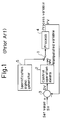
- Figs. 1 to 5 are block diagrams which show the configuration of the conventional apparatus.
- Fig. 1 shows a conventional process control device of the open loop type.
- a switch 1 In normal control state, a switch 1 is connected to control operation means 2.
- Both set value SV and process variable PV are inputted to deviation operation means 3 in which the deviation between these input signals is calculated.
- the deviation signal is inputted to the control operation means 2 in which the manipulated variable is calculated by using PID operation parameter, and the obtained manipulated variable is outputted to a process 4.
- the switch 1 is connected to an identification signal generator 5 periodically or when the deviation becomes large, and a step signal like a pulse signal is outputted from the identification signal generator 5 to the process 4 as an identification signal. Based upon the response from the process 4, control operation parameters are calculated in accordance with Ziegler-Nichols method etc. and set to the control operation means 2.
- Fig. 2 shows a conventional process control device of the limit sensitivity type.
- a deviation signal from the deviation operation means 3 is applied to the control operation means 2 and a limit cycle generator 6.
- Adding means 7 adds outputs of control operation means 2 and limit cycle generator 6, and supplies an output signal to the process 4 as a manipulated variable.
- the limit cycle generator 6 functions to change the manipulated variable outputted to the process 4 to a maximum value and to a minimum value periodically. Based upon the limit cycle or limit sensitivity at that time, the control operation parameters are calculated in accordance with Ziegler-Nichols method etc. and is set to the control operation means 2.
- Fig. 3 shows a conventional process control device of the response waveform type (for example, US-A-4,602,326).
- response waveform rule applying means 8 set value SV and deviation DV are applied.
- the response waveform rule applying means 8 is configured by such a tuning rule as Fuzzy rule etc.
- the control operation parameters are obtained by applying these rules to the overshoot of the process quantity, the attenuation ratio, the attenuation period, etc., and obtained parameters are set in control operation means 2.
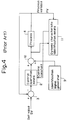
- Fig. 4 shows a conventional process control device of the adaptive control type.
- Adding means 10 adds outputs of the control operation means 2 and an identification signal generator 9, and generates an output to the process 4.
- dynamic characteristic identification means 11 receives the process variable and the output of the adding means 10, estimates control operation parameters, and sets the estimated parameters in control operation means 2. That is, a very small disturbance is generated in the identification signal generator 9.
- the control operation parameter is obtained from the dynamic characteristic of the process variable at that time and the obtained result is set in the control operation means 2.
- Fig. 5 shows the conventional process control device of the type equipped with a process model 13 (e.g., ISA Transaction Vol. 22, No. 3, p. 50, 51, and US-A-4,385,326).
- a signal from the control operation means 2 is outputted to the process 4 and also applied to the process model 13 through a high pass filter 12.
- the process model 13 modeling the process 4 is so configured that its parameters can be changed.
- Difference operation means 15 calculates the difference between the signal applied from the process 4 through a high pass filter 14 and the signal applied from the process model 13.
- Model parameter search means 16 receives a difference signal from difference operation means 15, and searches parameters that makes the difference signal minimum. The searched parameters are set as the parameters of the process model 13. Based on the parameters searched by the model parameter search means 16, control operation parameters are obtained, and the obtained control operation parameters are set in the control operation means 2.
- the above explained conventional process control device has following problems.
- the open loop type and the adaptive control type apparatus must give the identification signals to the process, and the limit sensitivity type apparatus must generate a persistent oscillation.
- a disturbance is applied to the process, and therefore, in case when we would obtain the control constant while the process control device is in operation, there occur many restrictions.
- the calculation is carried out continuously at model parameter search means 16, and thus, the amount of calculation increases as the whole.
- the load of a microprocessor becomes heavy when the function of each part is executed in accordance with the program installed in the microprocessor.
- Prior art document GB-A-2 086 082 describes a process control wherein a controller is response to a set point signal to control a process and a model of this process.
- a sequencer carries out a cycle in which step changes are made in the desired set point for the process, by a predetermined value, above and below the desired set point.
- a parameter identifier modifies the parameters of the process model and of the controller. In this process control, the cycle is repeated until the change in the values of the parameters between adjacent cycles is less than a predetermined about whereupon it is terminated.
- a main object of this invention is to provide a process control device (self-adaptive controller) wherein control constant can be reset in a short time without giving disturbance to process.
- Another object of this invention is to provide a process control device (self-adaptive controller) wherein the amount of calculation can be reduced and the load of the microprocessor can be minimized.
- the present invention provides a self-adaptive controller as specified in claim 1.
- Figs. 1 to 5 are block diagrams which show the structure of conventional apparatus.
- Fig. 6 is a structural diagram which shows one embodiment of a process control device in accordance with the invention.
- Fig. 7 is a flowchart to explain function of the apparatus in Fig. 6.
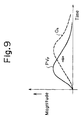
- Figs. 8 and 9 are diagrams of characteristic curves to explain the function of the embodiment of Fig. 6.
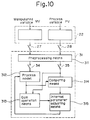
- Figs. 10 and 11 are diagrams which show respectively configuration and function of another embodiment in accordance with the invention.
- Fig. 12 is a flowchart of search method which uses simplex method.
- Fig. 13 is a block diagram which shows a main part of another embodiment in accordance with the invention.
- Fig. 14 is a waveform diagram which shows the change of process variable when a step like manipulated variable is applied to process.
- Fig. 15 is a flowchart which shows the function of the apparatus in Fig. 13.
- Fig. 16 is a waveform diagram which shows the change of process variable in other case when the step like manipulated variable is applied to the process.
- Fig. 17 is a structural block diagram of still other embodiment in accordance with the invention.
- Fig. 18 is a flowchart which shows function of the apparatus in Fig. 17.
- Fig. 19 is a waveform diagram which shows the change of the process variable when a step like signal is applied to the manipulating signal.
- Fig. 20 is a structural block diagram which shows still other embodiment in accordance with the invention.
- Fig. 21 is a flowchart which shows tuning action in the embodiment in Fig. 20.
- Fig. 6 is a structural block diagram which shows one embodiment of the process control device in accordance with the invention.
- 20 is control operation means, to which set value SV as a desired value and process variable PV which is the output of process 21 are inputted.
- control operation means 20 such operation, as proportional operation, integral operation, or differential operation is applied to the difference between set value SV and process variable PV so as to obtain manipulated variable MV.
- Manipulated variable MV which is the output of control operation means 20, is applied to process 21 to be controlled, and from process 21, process variable PV is outputted.
- manipulated variable MV and process variable PV are inputted and these data are held as time series data for a predetermined period.
- preprocessing means 23 is modeling means in which preprocessing means 231, process model 232, internal parameter adjusting means 233 and comparing means 234 are provided. Preprocessing such as filtering is applied, at preprocessing means 231, to the outputs of data gathering means 22. Then, manipulated variable MV is inputted to process model 232 and process variable PV is inputted to comparing means 234. Process, model 232 simulates process 21. The output of process model 232 is inputted to comparing means 234, and compared with process variable PV separately applied. This comparison result is inputted to internal parameter adjusting means 233 which functions to adjust the internal parameter in process model 232 so that the output of process model 232 may match the output of process 21.
- Control operation means 20 calculates manipulated variable MV based upon this new control parameter.
- 26 is calculation instruction means, wherein process variable PV and manipulated variable MV are inputted and the output is generated to manipulate switches 27 - 30 when the changes of the inputs exceed a predetermined value. Based upon this, a calculation instruction signal is applied to modeling means 23 so as to cause modeling means 23 to start its operation.
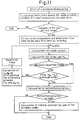
- Fig. 7 is a flowchart which shows one example of the functionof this embodiment.
- Data gathering, means 22 gathers manipulated variable MV and process variable PV as time series data at a predetermined period without any relation to this modeling operation.
- calculation instruction means 26 reads process variable (PV) and manipulated variable (MV) every predetermined period and functions to judge whether those changes are larger than the predetermined value. If the change is less than the predetermined value, the operation ends without giving any calculation instruction.
- this judgment is derived from such calculation, as shown in Fig. 8, that the area (slash part) is calculated by integrating the deviation of the process variable and the manipulated variable from respective steady states.
- modeling means 23 reads time series data ⁇ PV ⁇ concerning process variable PV and time series data ⁇ MV ⁇ concerning manipulated variable MV gathered by data gathering means 22.
- Preprocessing means 231 serves to eliminate the DC component and noise component thereof by filtering.
- Filtered time series data PV F , MV F concerning the process variable and the manipulated variable respectively are applied to process model 232 in which calculation of model output is carried out.
- This calculation is repeated until the repetition number reaches the maximum value, or until output O n of the process model becomes sufficiently close to time series data PV F concerning the process variable.
- accuracy K of process model 232 is calculated by estimation accuracy operating means 24.
- This accuracy K is calculated, for example, by following equation (3) or (4).
- K 1 - [ ⁇ PV F (i) - O(i) ⁇ 2 / ⁇ PV F (i) 2 ]
- K ⁇ PV F (i) ⁇ 2 / ⁇ O(i) ⁇ 2
- PV F (i) time series data of the process variable at time i
- O(i) output of process model 232 at time i.
- control operation-parameter operating means 25 calculates proportion/integration/differentiation constants, that is, control operation parameters, by using Ziegler-Nichols method, based upon obtained process model 232 of the first order lag process model.
- Control operation means 20 calculates manipulated variable MV by using this control operation parameter newly obtained.
- the process model is not necessarily such a first order system as shown by equation (2). Further, when there exists such measurable disturbance as load fluctuation in process 21, this disturbance can be used for the model calculation.
- gain K M is calculated based upon the integration ratio of the process variable and the output of the process model when the process gain is made 1, and dead time L M and first order lag coefficient ⁇ M are obtained by the repetition search method.
- Fig. 10 shows the structure of this embodiment. In this figure, other portions than the modeling means and data gathering means 22 are omitted since these portions are the same as shown in Fig. 6.
- 31 is modeling means which has similar function to modeling means 23 in Fig. 6.
- 311 is preprocessing means which has similar function to preprocessing means 231 in Fig. 6. Namely, process variable PV and manipulated variable MV stored in data gathering means 22 are filtered so as to eliminate the DC component and the noise component.
- 312 is process model which simulates the real process like process model 232. To this process model, the manipulated variable preprocessed by preprocessing means 311 is inputted. 313 is gain operation means, wherein the output of process model 312 and the process variable are inputted and the gain of process model 312 is calculated.
- 314 is comparing means for comparing the output of process model 312 and the process variable.
- 315 is internal adjusting means, wherein the output of comparing means 314 and the output of gain operation means 313 are inputted and the internal parameters are changed so that the difference between the output of process model 312 and the process variable may be enough small.
- the output of internal parameter adjusting means 315 is applied both to estimation accuracy operating means 24 and control operation-parameter operating means 25 in Fig. 6 so as to obtain the control operation parameters of control operation means 20.
- Switches 27, 28, 34 and 35 are controlled by calculation instruction means 26. Function of this embodiment is explained in the following.
- Fig. 11 is a flowchart which shoMs the function of this embodiment.
- Calculation instruction means 26 shown in Fig. 6 reads periodically manipulated variable brv and process variable PV, and only when those fluctuations become large, the following steps are executed.
- time series data ⁇ PV ⁇ and ⁇ MV ⁇ concerning the manipulated variable and the process variable respectively are filtered so as to eliminate the DC component and the noise component, and then the output of the process model is calculated by process model 312.
- process model gain K M is calculated by use of following equation (6).
- K M [ ⁇ O(n) ⁇ PV F (n) ⁇ ]/ ⁇ O(n) 2 ⁇
- O(n) the value obtained by the above equation (5), that is, the output of process model 312 when process model gain K M is made 1.
- dead time L M of process model 312 and first order lag coefficient ⁇ M are adjusted so as to minimize the above difference. Then, process model 312 is restarted, and such operations are carried out, that the output is calculated in accordance with equation (5) and that process model gain K M is calculated in accordance with equation (6).
- control operation-parameter operating means 25 calculates proportion/ integration/ differentiation constant, that is, control operation parameters, by using Ziegler-Nichols method, based upon obtained process model 312 of the first order lag process model.
- Control operation means 20 calculates the manipulated variable by using this control operation parameter newly obtained. Further, internal parameter adjusting means 315 calculates dead time L M and first order lag coefficient ⁇ M by the repetition search method which uses simplex method.
- process model gain K M is automatically determined when dead L M time and first order lag coefficient ⁇ M are determined, and thus, the numbers of repetition search can be reduced.
- simplex method can be used for a method in case when internal parameter adjusting means 315 searches the internal parameter of process model 312.
- simplex method some points having geometrical arrangement on R n are chosen, and search is carried out by comparing the values of the object function at these points.
- This method is disclosed on p.284 - 287, "Non-linear Programming" by Hiroshi Imano and Hiroshi Yamashita, published from "Nippon Kagaku Gijustu Rengou”.
- the I/O data of the usual simplex method are discrete values in principle. Therefore, such problem occurs, that since the object function enters into the space of the discrete values, search becomes impossible. Further, there is such restriction that parameters such as time constant and dead time must be positive numbers.
- Fig. 12 shows procedure of the simplex method, in which the above mentioned restrictions are eliminated.
- the process data gathered by data gathering means 22 corresponds to geometrical points x on R n
- the object function corresponds to function f( ) of at this geometrical point.
- the search is carried out by comparing the values of the object function f( ).
- x h is replaced by x c .
- x l is replaced by (x i + X l )/2, and the operation returns to the step that x h , x s , x l and x m were decided.
- each component side which composes an initial polygon is made longer than sampling period and although the initial polygon is remade at least once, it is also possible that either of these two conditions is satisfied.
- Fig. 13 shows a still other embodiment.
- initial values for proportional constant, integral constant and differential constant, and sampling period must be set prior to the control operation. If these values are not set properly, automatic adjustment of the control operation parameters can not be done properly, and as the result, the control characteristic becomes worse.
- both the control operation parameters and the sampling period are previously tuned.
- the same reference numerals are attached to the same components as in Fig. 6 and the explanation for these components is omitted.
- 40 is step input generating means which applies step like manipulated variable to process 21.
- the process increases gradually as shown in Fig. 14.
- 41 is first monitoring means which monitors the process variable of process 21. Namely, after application of the step like manipulated variable from step input generating means 40, time width t 1 (first time width) until the process variable reaches a first predetermined value, for example, 1% of full scale, is measured.
- sampling period calculating means wherein the first time width measured by the first monitoring means 41 is inputted and based upon this, sampling period of data gathering means 22 is calculated.
- 43 is a second monitoring means which monitors the process variable from process 21. Namely, after application of the step like manipulated variable from step input generating means 40, time width t 2 (second time width) until the process variable reaches a second predetermined value larger than the first predetermined value, for example, 2% of full scale, is measured.
- sampling period correcting means wherein the second time width measured by the second monitoring means 43 is inputted and the sampling period calculated by sampling period calculating means 42 is corrected.
- this switch is a switch which composes a sampler. In the first place, this switch is made ON every period calculated by sampling period calculating means 42, and later, is made ON every period corrected by sampling period correcting means 44. And, in accordance with these sampling periods, the process data is introduced into data gathering means 22. The gathered data is inputted to modeling means 23, and its internal parameters are adjusted, as explained in the embodiment of Fig. 6, until the output of process model 232 may coincide with the process variable. Based upon this internal parameters, control constant are calculated.
- elapsed time t 2 after application of the step like manipulated variable to the process that is, the second time width is measured, and judged as to whether this time width t 2 is larger than the twice of time width t 1 obtained by step (1).
- interpolation is applied to previously gathered data so as to use these data as the data for new sampling period t s .
- step (3) data gathering operation of the process variable terminates, and arrangement of time series data ⁇ PV ⁇ and ⁇ MV ⁇ with respect to the process variable and the manipulated variable, stored in data gathering means 22, is carried out. Based upon these time series data, the internal parameters of process model is adjusted by modeling means 23, and control constants are obtained.
- control constants are used as an initial value. Then, data gathering is carried out by sampling period t s , and the control parameters are calculated in accordance with the procedure explained in Fig. 7.
- step like manipulated variable is applied once at the beginning of control.
- process variable PV can settle by one time application of the step like manipulated variable as shown in Fig. 16(a).
- Applied period T of the step like manipulated variable is set to a fixed time or a time until the process variable reaches ⁇ P max .
- control constants are derived from the internal parameters of the modeling means by use of Ziegler-Nichols method, least square method or maximum likelihood degree method can be used.
- process data is gathered by the data gathering means and the modeling means is started so as to correct the internal parameters of the process model only when the change occurs in the process data. Then, estimation accuracy of the process model is calculated, and the control constants are calculated. Therefore, in this embodiments, identification signals are unnecessary, and thus, these embodiments have such advantage that extra disturbances are not applied to the process.
- the search time can be shortened.
- Fig. 17 shows a structural block diagram of a still other embodiment in accordance with this invention.
- estimation accuracy operating means 24 shown in Fig. 6 is omitted.
- manual instruction means 50 and step signal generating means 51 are provided, wherein step signal generating means 51 generates a step like pulse signal to process 21 based upon the instruction applied from instruction means 50.
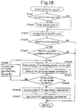
- Fig. 18 is a flowchart which shows tuning operation for calculating the control operation parameters, started at a predetermined period in the embodiment in Fig. 17.
- step 1 judgment as to whether instruction for generating the step signal (the instruction from instruction means 50) exists, is conducted (step 1).
- a step signal having a fixed width is generated from step signal generating means 51 and is applied to manipulated variable MV in control operation means 20 (step 2).
- step 2 is skipped.
- Fig. 19 is a waveform diagram of manipulated variable MV and process variable PV, wherein the change of the process variable PV is shown when the step like signal is applied to manipulated variable MV.
- process variable PV When the manipulated variable changing step-like as shown in (a) is applied to process variable PV, process variable PV responds in such a manner as shown in (b) in accordance with its dynamic characteristic.
- Data gathering means 22 receives manipuiated variable MV and process variable PV, and holds these data as time series data for a predetermined period (step 3).
- Calculation instruction means 26 reads manipulated variable MV and process variable PV, and monitors, at every identification period, whether the fluctuation of these signals exceeds a predetermined value (step 5). When the fluctuation of these signals is less than the predetermined value, it is judged that the control is satisfactory state, and the operation terminates without generating a trigger signal. As shown in Fig. 8, the above judgment is done based upon the size of areas (slash parts) calculated by integrating the deviation of process variable PV from its steady state and the deviation of manipulated variable MV from its steady state for a fixed time.
- Modeling means 23 when it receives calculation instruction TRG, functions to estimate the dynamic characteristic of process 21 by using the change of manipulated variable MV and the response waveform of process variable PV from process 21, based upon the data applied, for a predetermined time, from data gathering means (steps 6 to 9).
- control operation means 20 calculates, based upon the obtained parameters of process model 232, proportion(PB)/ integration(TI)/ differentiation(TD) parameters in accordance with following equation (7), for example, by use of Ziegler-Nichols method, and the obtained operation parameters are set in control operation means 25 (steps 10 and 11).
- PB/K M a(L M / ⁇ M ) 2 + b(L M / ⁇ M ) + c
- Control operation means 20 calculates manipulated signal MV by using newly set operation parameters.
- Step signal generating means 51 applies a pulse signal in place of the step signal when the process is integral type process.
- PI operation parameter can be set to an optimum value arbitrarily, if necessary, by applying a step like signal to the manipulated variable in automatic control state, in accordance with the instruction signal. And therefore, operability of this embodiment can be improved sufficiently.
- the amount of calculation can be reduced as the whole.
- Fig. 20 is a structural block diagram which shows a still other embodiment in accordance with the invention.
- drawbacks of the prior art shown in Fig. 5 are overcome.
- the signal to process model 13 is applied from control operation means 2 through high pass filter 12.
- DC and noise components can be eliminated from the signal and it has such feature that calculation in the process model becomes comparatively simple.
- this prior art has following drawbacks.
- process model 13 is a linear characteristic type so that model parameter search means 16 may search accurately the parameters which reduce the difference signal applied from difference operation means 15. Therefore, it is impossible to set high-low-limit in the output and also to use a nonlinear characteristic type model for the process model.
- the embodiment shown in Fig. 20 overcomes these problems, wherein the amount of calculation in the process model or in searching the parameters can be reduced, the calculation in the process model can be done accurately corresponding to the real process, and non-linear characteristic type model can be used for the process model.
- Signal MV from control operation means 20 is applied to process model 232 through data gathering means 22.
- Signal MO from process model 232 is applied to a first band pass filter so as to eliminate the DC and noise components.
- Signal PV from process 21 is applied to a second band pass filter 236 having the same characteristic as that of first band pass filter 235, through data gathering means 22.
- first and second band pass filters 235, 236 conduct such filtering calculation as shown in the following equation (8).
- PVF (1 - ⁇ ) ⁇ PVF + a ⁇ (PV - PVo)
- PVF applied time series data
- PVo DC and noise components
- ⁇ filter constant.
- Calculation instruction means 26 receives signal PV from process 21 and signal PVF from second band pass filter 236, and when either of these signals changes, calculation instruction signal TRG is generated.
- Model parameter search means 233 receives signal MOF from first band pass filter 235 and signal PVF from second band pass filter 236, and based upon calculation instruction signal TRG from calculation instruction means 26, searches parameters that make the difference of the signals applied from the first and second, band pass filters minimum. And the parameters of process model 232 is varied based upon searched parameters.
- Control operation-parameter operating means 25 calculates operation-parameters of control operation means 20 and sets these values in control operation means 20.
- Calculation instruction signal TRG from calculation instruction means 26 is applied, in addition to model parameter search means 23, to process model 232, first band pass filter 235 and control operation parameter operating means 25 simultaneously, which start calculation based upon the calculation instruction signal.
- model parameter search means 23 to process model 232, first band pass filter 235 and control operation parameter operating means 25 simultaneously, which start calculation based upon the calculation instruction signal.
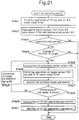
- Fig. 21 is a flowchart which shows tuning action for control operation parameter, started at a predetermined period.
- Second band pass filter 236 receives process variable PV from process 21, and conducts such filtering calculation as shown by equation (8) (step 1).
- Calculation instruction means 26 reads the time series data concerning process variable PV and output time series data PVF of second band pass filter 236, and monitors, at every identification period, whether the change of these data is larger than a predetermined value (step 4).
- calculation instruction means 26 When the change of PV or PVF exceeds the fixed value, calculation instruction means 26 generates calculation instruction signal TRG.
- Process model 232 which receives this calculation instruction signal TRG, reads the time series data of manipulated variable MV gathered at step 2 (the same signal as the manipulated variable applied to process 21), and calculates model output MO in accordance with equation (5) (step 5).
- Output MO of process model 232 is applied to first band pass filter 235 in which filtering calculation is carried out in accordance with equation (8) (step 6). By the filtering operation, the DC and noise components included in model output MO are eliminated.
- Model parameter search means 233 receives time series data MOF from first band pass filter 235 and time series data PVF from second band pass filter 236, and conducts calculation for searching optimum parameters for process model 232.
- parameter search means 23 functions to search the best combination of time constant T M and dead time L M of the model, by which evaluation function CRIT is made minimum.
- gain K M of process model 232, dead time L M , and first order lag coefficient ⁇ M are corrected respectively until the output of process model 232 becomes sufficiently close to the output of process 21 (i.e., the difference of process model becomes less than a fixed value), by repeating the operation from step 5 to step 9.
- control operation-parameter operating means 25 calculates, based upon the obtained parameters of process model 232, proportion (PB)/ integration(TI)/ differentiation(TD) parameters in accordance with equation (7), for example, by use of Ziegler-Nichols method, and the obtained operation parameters are set in control operation means 20 (steps 10 and 11).
- Control operation means 20 calculates manipulated variable MV by using newly set operation parameters.
- Process model 232 is not necessarily first order lag type system. Further, when measurable disturbance such as load fluctuation exists in process 21, this disturbance can be used for the model calculation.
- gain K M is determined by totalizing ratio of the process variable and the output of the process model when the gain of process model is made 1. Then, dead time L M and first order lag coefficient ⁇ M are determined by, using repetition search method.
- This embodiment has following advantages in comparison with the conventional apparatus shown in Fig. 5.
Landscapes
- Engineering & Computer Science (AREA)
- Physics & Mathematics (AREA)
- General Physics & Mathematics (AREA)
- Automation & Control Theory (AREA)
- Health & Medical Sciences (AREA)
- Artificial Intelligence (AREA)
- Computer Vision & Pattern Recognition (AREA)
- Evolutionary Computation (AREA)
- Medical Informatics (AREA)
- Software Systems (AREA)
- Feedback Control In General (AREA)
Description
- This invention relates to a process control device which controls a process, and in particular to a process a control device which has a function to automatically adjust control constant such as a proportional constant (P) and an integral constant (I) to an optimum value. This invention relates in still more detail to a process control device having a process model internally to estimate a dynamic characteristic of the process to be controlled, wherein PI operation parameters are determined based upon the estimate result by the process model (self-adaptive controller).
- In order to control a process to an optimum condition, it is necessary to search the dynamic characteristic of the process and to calculate the control operation parameters (constants) for calculation of the manipulated variable. An open loop type, a limit sensitivity type, a response waveform type, an adaptive control type, a type equipped with process model are known for these process control devices.
- Figs. 1 to 5 are block diagrams which show the configuration of the conventional apparatus.
- Fig. 1 shows a conventional process control device of the open loop type. In normal control state, a
switch 1 is connected to control operation means 2. Both set value SV and process variable PV are inputted to deviation operation means 3 in which the deviation between these input signals is calculated. The deviation signal is inputted to the control operation means 2 in which the manipulated variable is calculated by using PID operation parameter, and the obtained manipulated variable is outputted to aprocess 4. - The
switch 1 is connected to an identification signal generator 5 periodically or when the deviation becomes large, and a step signal like a pulse signal is outputted from the identification signal generator 5 to theprocess 4 as an identification signal. Based upon the response from theprocess 4, control operation parameters are calculated in accordance with Ziegler-Nichols method etc. and set to the control operation means 2. - Fig. 2 shows a conventional process control device of the limit sensitivity type. A deviation signal from the deviation operation means 3 is applied to the control operation means 2 and a
limit cycle generator 6. Adding means 7 adds outputs of control operation means 2 andlimit cycle generator 6, and supplies an output signal to theprocess 4 as a manipulated variable. - The
limit cycle generator 6 functions to change the manipulated variable outputted to theprocess 4 to a maximum value and to a minimum value periodically. Based upon the limit cycle or limit sensitivity at that time, the control operation parameters are calculated in accordance with Ziegler-Nichols method etc. and is set to the control operation means 2. - Fig. 3 shows a conventional process control device of the response waveform type (for example, US-A-4,602,326). To response waveform rule applying means 8, set value SV and deviation DV are applied. The response waveform rule applying means 8 is configured by such a tuning rule as Fuzzy rule etc. The control operation parameters are obtained by applying these rules to the overshoot of the process quantity, the attenuation ratio, the attenuation period, etc., and obtained parameters are set in control operation means 2.
- Fig. 4 shows a conventional process control device of the adaptive control type. Adding means 10 adds outputs of the control operation means 2 and an
identification signal generator 9, and generates an output to theprocess 4. Further, dynamic characteristic identification means 11 receives the process variable and the output of the addingmeans 10, estimates control operation parameters, and sets the estimated parameters in control operation means 2. That is, a very small disturbance is generated in theidentification signal generator 9. The control operation parameter is obtained from the dynamic characteristic of the process variable at that time and the obtained result is set in the control operation means 2. - Fig. 5 shows the conventional process control device of the type equipped with a process model 13 (e.g., ISA Transaction Vol. 22, No. 3, p. 50, 51, and US-A-4,385,326). A signal from the control operation means 2 is outputted to the
process 4 and also applied to theprocess model 13 through ahigh pass filter 12. Theprocess model 13 modeling theprocess 4 is so configured that its parameters can be changed. Difference operation means 15 calculates the difference between the signal applied from theprocess 4 through ahigh pass filter 14 and the signal applied from theprocess model 13. Model parameter search means 16 receives a difference signal from difference operation means 15, and searches parameters that makes the difference signal minimum. The searched parameters are set as the parameters of theprocess model 13. Based on the parameters searched by the model parameter search means 16, control operation parameters are obtained, and the obtained control operation parameters are set in the control operation means 2. - The above explained conventional process control device has following problems.
- That is, the open loop type and the adaptive control type apparatus must give the identification signals to the process, and the limit sensitivity type apparatus must generate a persistent oscillation. In these types, a disturbance is applied to the process, and therefore, in case when we would obtain the control constant while the process control device is in operation, there occur many restrictions.
- Further, in the responsive waveform type, several times of waveform observation are necessary until the control operation parameters are settled, and therefore, it needs a certain time.
- Accordingly, either of these control devices could not set freely the control operation parameters.
- Further, in the type equipped with the process model, the calculation is carried out continuously at model parameter search means 16, and thus, the amount of calculation increases as the whole. As the result, it has such a drawback that the load of a microprocessor becomes heavy when the function of each part is executed in accordance with the program installed in the microprocessor.
- Prior art document GB-A-2 086 082 describes a process control wherein a controller is response to a set point signal to control a process and a model of this process. A sequencer carries out a cycle in which step changes are made in the desired set point for the process, by a predetermined value, above and below the desired set point. A parameter identifier modifies the parameters of the process model and of the controller. In this process control, the cycle is repeated until the change in the values of the parameters between adjacent cycles is less than a predetermined about whereupon it is terminated.
- In prior art document ADAPTIVE CONTROL K. J. Aström & B. Wittemark May 1989, Addison-Wesley publishing Company, pp. 443 to 458, it is described that in an adaptive control with an estimator the value of the changes of a control signal and a process output can be used as criteria for deciding whether the parameters of a model are convenient or not.
- Finally, prior art document DATABASE INSPEC: Operations Research Society of America 41st annual meeting, New Orleans, USA, 26-28 April 1972, K. A. FEGLEY, J. F. BURNS, R. M. HOLLIS "Process identification via mathematical programming", discloses that it is known to use the simplex method in order to determine a mathematical model of a process.
- A main object of this invention is to provide a process control device (self-adaptive controller) wherein control constant can be reset in a short time without giving disturbance to process. Another object of this invention is to provide a process control device (self-adaptive controller) wherein the amount of calculation can be reduced and the load of the microprocessor can be minimized.
- To solve this object the present invention provides a self-adaptive controller as specified in
claim 1. - Figs. 1 to 5 are block diagrams which show the structure of conventional apparatus.
- Fig. 6 is a structural diagram which shows one embodiment of a process control device in accordance with the invention.
- Fig. 7 is a flowchart to explain function of the apparatus in Fig. 6.
- Figs. 8 and 9 are diagrams of characteristic curves to explain the function of the embodiment of Fig. 6.
- Figs. 10 and 11 are diagrams which show respectively configuration and function of another embodiment in accordance with the invention.
- Fig. 12 is a flowchart of search method which uses simplex method.
- Fig. 13 is a block diagram which shows a main part of another embodiment in accordance with the invention.
- Fig. 14 is a waveform diagram which shows the change of process variable when a step like manipulated variable is applied to process.
- Fig. 15 is a flowchart which shows the function of the apparatus in Fig. 13.
- Fig. 16 is a waveform diagram which shows the change of process variable in other case when the step like manipulated variable is applied to the process.
- Fig. 17 is a structural block diagram of still other embodiment in accordance with the invention.
- Fig. 18 is a flowchart which shows function of the apparatus in Fig. 17.
- Fig. 19 is a waveform diagram which shows the change of the process variable when a step like signal is applied to the manipulating signal.
- Fig. 20 is a structural block diagram which shows still other embodiment in accordance with the invention.
- Fig. 21 is a flowchart which shows tuning action in the embodiment in Fig. 20.
- Fig. 6 is a structural block diagram which shows one embodiment of the process control device in accordance with the invention. In Fig. 6, 20 is control operation means, to which set value SV as a desired value and process variable PV which is the output of
process 21 are inputted. In control operation means 20, such operation, as proportional operation, integral operation, or differential operation is applied to the difference between set value SV and process variable PV so as to obtain manipulated variable MV. - Manipulated variable MV which is the output of control operation means 20, is applied to process 21 to be controlled, and from
process 21, process variable PV is outputted. - 22 is data gathering means, wherein manipulated variable MV and process variable PV are inputted and these data are held as time series data for a predetermined period.
- 23 is modeling means in which preprocessing means 231,
process model 232, internal parameter adjusting means 233 and comparingmeans 234 are provided. Preprocessing such as filtering is applied, at preprocessing means 231, to the outputs of data gathering means 22. Then, manipulated variable MV is inputted to processmodel 232 and process variable PV is inputted to comparingmeans 234. Process,model 232 simulatesprocess 21. The output ofprocess model 232 is inputted to comparingmeans 234, and compared with process variable PV separately applied. This comparison result is inputted to internal parameter adjusting means 233 which functions to adjust the internal parameter inprocess model 232 so that the output ofprocess model 232 may match the output ofprocess 21. - 24 is estimation accuracy operating means, wherein the output of modeling means 23 is inputted so as to calculate accuracy of
process model 232. 25 is control operation-parameter operating means, wherein the outputs of internal parameter adjusting means 232 and estimation accuracy operating means 24 are inputted and the control parameters calculated based upon the output thereof are set in control operation means 20. Control operation means 20 calculates manipulated variable MV based upon this new control parameter. - 26 is calculation instruction means, wherein process variable PV and manipulated variable MV are inputted and the output is generated to manipulate switches 27 - 30 when the changes of the inputs exceed a predetermined value. Based upon this, a calculation instruction signal is applied to modeling means 23 so as to cause modeling means 23 to start its operation.
- The function of this embodiment is explained in the following.
- Fig. 7 is a flowchart which shows one example of the functionof this embodiment. Data gathering, means 22 gathers manipulated variable MV and process variable PV as time series data at a predetermined period without any relation to this modeling operation. In Fig. 7, calculation instruction means 26 reads process variable (PV) and manipulated variable (MV) every predetermined period and functions to judge whether those changes are larger than the predetermined value. If the change is less than the predetermined value, the operation ends without giving any calculation instruction.
- For example, this judgment is derived from such calculation, as shown in Fig. 8, that the area (slash part) is calculated by integrating the deviation of the process variable and the manipulated variable from respective steady states.
- When the change is large, modeling means 23 reads time series data {PV} concerning process variable PV and time series data {MV} concerning manipulated variable MV gathered by data gathering means 22. Preprocessing means 231 serves to eliminate the DC component and noise component thereof by filtering.
- This filtering is given by following equation (1), where PVF: the time series data of the process variable, PVO: the DC or noise components, and α: filtering constant.

- Filtered time series data PVF, MVF concerning the process variable and the manipulated variable respectively are applied to
process model 232 in which calculation of model output is carried out. - Though this calculation is different by the process model, assumed that the n time model output is On, the above calculation is given by following equation (2), where KM: gain of process model, LM: dead time of process model, βM: first order lag coefficient of process model, MVF(n - LM): this is done by calculation by the use of a value MVF before time LM.

- This calculation is repeated until the repetition number reaches the maximum value, or until output On of the process model becomes sufficiently close to time series data PVF concerning the process variable.
- When the repetition number does not reach the maximum value, or when the difference between output On of
process model 232 and time series data PVF concerning the process variable is not small as shown in Fig. 9, gain KM, dead time LM, and first order lag coefficient βM are adjusted so that this difference becomes small (that is, to cause the curve of output On to move to the direction of an arrow), and thenprocess model 232 is re-started. - When the repetition reaches the maximum number, or when the difference between output On of
process model 232 and time series data PVF concerning process variable becomes enough small, accuracy K ofprocess model 232 is calculated by estimation accuracy operating means 24. This accuracy K is calculated, for example, by following equation (3) or (4).

process model 232 at time i. - When this estimation accuracy is higher than a predetermined value, control operation-parameter operating means 25 calculates proportion/integration/differentiation constants, that is, control operation parameters, by using Ziegler-Nichols method, based upon obtained
process model 232 of the first order lag process model. - Control operation means 20 calculates manipulated variable MV by using this control operation parameter newly obtained.
- By the way, the process model is not necessarily such a first order system as shown by equation (2). Further, when there exists such measurable disturbance as load fluctuation in
process 21, this disturbance can be used for the model calculation. - In the embodiment shown in Fig. 6, calculation must be done repeatedly with respect to the whole internal parameters of
process model 232, that is, gain KM, dead time LM, first order lag coefficient βM, by changing slightly these values, and therefore, it takes a lot of times for calculation. The following embodiment can overcome this problem. In this embodiment, gain KM is calculated based upon the integration ratio of the process variable and the output of the process model when the process gain is made 1, and dead time LM and first order lag coefficient βM are obtained by the repetition search method. - Fig. 10 shows the structure of this embodiment. In this figure, other portions than the modeling means and data gathering means 22 are omitted since these portions are the same as shown in Fig. 6.
- In Fig. 10, 31 is modeling means which has similar function to modeling means 23 in Fig. 6. 311 is preprocessing means which has similar function to preprocessing means 231 in Fig. 6. Namely, process variable PV and manipulated variable MV stored in data gathering means 22 are filtered so as to eliminate the DC component and the noise component.
- 312 is process model which simulates the real process like
process model 232. To this process model, the manipulated variable preprocessed by preprocessing means 311 is inputted. 313 is gain operation means, wherein the output ofprocess model 312 and the process variable are inputted and the gain ofprocess model 312 is calculated. - 314 is comparing means for comparing the output of
process model 312 and the process variable. 315 is internal adjusting means, wherein the output of comparingmeans 314 and the output of gain operation means 313 are inputted and the internal parameters are changed so that the difference between the output ofprocess model 312 and the process variable may be enough small. - The output of internal parameter adjusting means 315 is applied both to estimation accuracy operating means 24 and control operation-parameter operating means 25 in Fig. 6 so as to obtain the control operation parameters of control operation means 20.
Switches - Fig. 11 is a flowchart which shoMs the function of this embodiment. Calculation instruction means 26 shown in Fig. 6 reads periodically manipulated variable brv and process variable PV, and only when those fluctuations become large, the following steps are executed.
- That is, at preprocessing means 311, time series data {PV} and {MV} concerning the manipulated variable and the process variable respectively are filtered so as to eliminate the DC component and the noise component, and then the output of the process model is calculated by
process model 312. - In this calculation, process model gain KM is made 1, and the calculation is carried out by following equation (5).

- Next, at gain operation means 313, process model gain KM is calculated by use of following equation (6).

process model 312 when process model gain KM is made 1. - These calculations are carried out repeatedly until the repetition number reaches the maximum numbers, or until the product of output On of
process model 312 and process model gain KM calculated by gain operation means 313 becomes sufficiently close to time series data PVF of the process variable. - When all conditions in the above are not satisfied, dead time LM of
process model 312 and first order lag coefficient βM are adjusted so as to minimize the above difference. Then,process model 312 is restarted, and such operations are carried out, that the output is calculated in accordance with equation (5) and that process model gain KM is calculated in accordance with equation (6). - When the whole conditions are satisfied, accuracy K of
process model 312 is calculated. When this estimation accuracy is less than a predetermined value, control operation-parameter operating means 25 calculates proportion/ integration/ differentiation constant, that is, control operation parameters, by using Ziegler-Nichols method, based upon obtainedprocess model 312 of the first order lag process model. - Control operation means 20 calculates the manipulated variable by using this control operation parameter newly obtained. Further, internal parameter adjusting means 315 calculates dead time LM and first order lag coefficient βM by the repetition search method which uses simplex method.
- Further, if process model gain KM becomes necessary at the beginning of repetition, the last time process gain KM is used for this. In this embodiment, process model gain KM is automatically determined when dead LM time and first order lag coefficient βM are determined, and thus, the numbers of repetition search can be reduced.
- For example, simplex method can be used for a method in case when internal parameter adjusting means 315 searches the internal parameter of
process model 312. By the simplex method, some points having geometrical arrangement on Rn are chosen, and search is carried out by comparing the values of the object function at these points. This method is disclosed on p.284 - 287, "Non-linear Programming" by Hiroshi Imano and Hiroshi Yamashita, published from "Nippon Kagaku Gijustu Rengou". - However, the I/O data of the usual simplex method are discrete values in principle. Therefore, such problem occurs, that since the object function enters into the space of the discrete values, search becomes impossible. Further, there is such restriction that parameters such as time constant and dead time must be positive numbers.
- Fig. 12 shows procedure of the simplex method, in which the above mentioned restrictions are eliminated. In this figure, assumed that the process data gathered by data gathering means 22 corresponds to geometrical points x on Rn, and that the object function corresponds to function f( ) of at this geometrical point. The search is carried out by comparing the values of the object function f( ). Further, assumed that among points x, a point where object function f( ) takes the maximum value, is xh, that among points x, a point where object function f( ) takes the second magnitude value, is xs, that among points x, a point where object function f( ) takes the minimum value, is x1, and that a centroid of the graphic pattern which has points x as summits, is xm. Further, the following points are defined as follows:
- Reflection plane:
- xr = (1 + α) ∗ xm - α xh
α > 0 - Expansion:
- Xe = γ ∗ xr + (1 - γ)∗ xm
γ > 1 - Contraction:
- xc = β∗ xh + (1 - β)∗ xm
β ∈ (0.1) - Reduction:
- The whole summits are reduced to the direction of x1.
- In Fig. 12, after initialization, (n + 1) affine independent convex hulls on Rn are generated by a first simplex. Next, the above xh, xs, xl and xm are decided, and judgment as to whether it can be converged is carried out. This judgment is conducted in a way whether the following equation can be satisfied.

- When the convergence condition is satisfied and if the convergence is the first time, simplex is generated at this point, and the operation repeats from the step that xh, xs, xl, xm were decided in the above. The operation ends when the convergence is accomplished more than two times.
- When it is not converged, xr and f(xr) are calculated, and judgment is carried out whether the foilowing equation is satisfied.

- When this condition is not satisfied, judgment is carried out as to whether the following equation is satisfied.

- When the above equation is satisfied, xh is replaced by xr. When the above equation is not satisfied, xc and f(xc) are obtained, by leaving the equation as it is, and judgment is carried out whether the following equation is satisfied.

- When the above equation is satisfied, xh is replaced by xc. When the above equation is not satisfied, xl is replaced by (xi + Xl)/2, and the operation returns to the step that xh, xs, xl and xm were decided.
- On the other hand, when the equation f(xr)≦f(xs) is satisfied, judgment as to whether the following equation is satisfied, is conducted.

- When the above equation is not satisfied, xe and f(xe) are obtained, and judgment as to whether the following equation is satisfied, is carried out.

- When the above equation is satisfied, xh is replaced by xe. When the above equation is not satisfied and when f(xr)≧f(xl) is satisfied, xh is replaced by xr, and the operation returns to the step that xh, xs, xl and xm were decided.
- In contrast to the usual simplex method, in this embodiment, when the convergence is the first time, simplex is generated at this point, and the simplex method is carried out once again. Therefore, such a disadvantage that the object function enters into the subspace can be avoided, and negative number can be used for such parameters.
- By the way, in this embodiment, although the length of each component side which composes an initial polygon is made longer than sampling period and although the initial polygon is remade at least once, it is also possible that either of these two conditions is satisfied.
- Fig. 13 shows a still other embodiment. In the embodiment in Fig. 6, initial values for proportional constant, integral constant and differential constant, and sampling period must be set prior to the control operation. If these values are not set properly, automatic adjustment of the control operation parameters can not be done properly, and as the result, the control characteristic becomes worse. In the embodiment shown in Fig. 13, in order to eliminate these situations, both the control operation parameters and the sampling period are previously tuned. In this embodiment, the same reference numerals are attached to the same components as in Fig. 6 and the explanation for these components is omitted.
- In Fig. 13, 40 is step input generating means which applies step like manipulated variable to process 21. By this input of the manipulated variable, the process increases gradually as shown in Fig. 14. 41 is first monitoring means which monitors the process variable of
process 21. Namely, after application of the step like manipulated variable from step input generating means 40, time width t1 (first time width) until the process variable reaches a first predetermined value, for example, 1% of full scale, is measured. - 42 is sampling period calculating means, wherein the first time width measured by the first monitoring means 41 is inputted and based upon this, sampling period of data gathering means 22 is calculated. 43 is a second monitoring means which monitors the process variable from
process 21. Namely, after application of the step like manipulated variable from step input generating means 40, time width t2 (second time width) until the process variable reaches a second predetermined value larger than the first predetermined value, for example, 2% of full scale, is measured. - 44 is sampling period correcting means, wherein the second time width measured by the second monitoring means 43 is inputted and the sampling period calculated by sampling period calculating means 42 is corrected.
- 45 is a switch which composes a sampler. In the first place, this switch is made ON every period calculated by sampling period calculating means 42, and later, is made ON every period corrected by sampling
period correcting means 44. And, in accordance with these sampling periods, the process data is introduced into data gathering means 22. The gathered data is inputted to modeling means 23, and its internal parameters are adjusted, as explained in the embodiment of Fig. 6, until the output ofprocess model 232 may coincide with the process variable. Based upon this internal parameters, control constant are calculated. - Next, the function of this embodiment is explained in accordance with a flowchart shown in Fig. 15. The operation is executed at a predetermined period at the initial stage of control. In the first place, the condition of start is judged whether it is initial state or not. When it is judged as an initial start, a step like manipulated variable is applied to process 21.
- On the other hand, when the start is not an initial one, judgment as to whether the process corresponds to either of the following three steps, is judged. If the process does not correspond to any of these steps, the operation ends without doing anything.
- (1) When process variable PV exceeds 1 % of full scale.
- (2) When process variable PV exceeds 2 % of full scale.
- (3) When process variable PV is settled to a fixed value or it becomes integer times of the sampling period obtained by sampling
period correcting means 44. - When the process variable corresponds to the above step (1), elapsed time t1 after application of the step like manipulated variable to the process, that is, the first time width is measured, and one to integer number of this time t1 is used as sampling time ts. For example, sampling time ts is made as follows:

- When the process variable corresponds to the above step (2), elapsed time t2 after application of the step like manipulated variable to the process, that is, the second time width is measured, and judged as to whether this time width t2 is larger than the twice of time width t1 obtained by step (1). When time width t2 is larger than the twice of t1, sampling time is made as follows:
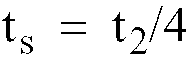
- In this case, interpolation is applied to previously gathered data so as to use these data as the data for new sampling period ts.
- When the process variable corresponds to the above step (3), data gathering operation of the process variable terminates, and arrangement of time series data {PV} and {MV} with respect to the process variable and the manipulated variable, stored in data gathering means 22, is carried out. Based upon these time series data, the internal parameters of process model is adjusted by modeling means 23, and control constants are obtained.
- The obtained control constants are used as an initial value. Then, data gathering is carried out by sampling period ts, and the control parameters are calculated in accordance with the procedure explained in Fig. 7.
- In this embodiment, the step like manipulated variable is applied once at the beginning of control. In case of the non-integral type process, process variable PV can settle by one time application of the step like manipulated variable as shown in Fig. 16(a).
- However, in case of the integral type process, offset remains as shown in Fig. 16(b). Accordingly, in this case, after the process variable is settled, a step like signal is applied to opposite direction so as to eliminate the above offset, and then, sampling of the process data goes on. If change of the process variable exceeds a fixed tolerance, the step like signal is applied to opposite direction even though the process variable has not been settled yet, so that the process variable may not become too much large. Further, it is possible to judge the process whether it is integral type or not from the amount of the offset.
- Applied period T of the step like manipulated variable is set to a fixed time or a time until the process variable reaches ΔPmax.
- Further, though in the above embodiments, the control constants are derived from the internal parameters of the modeling means by use of Ziegler-Nichols method, least square method or maximum likelihood degree method can be used.
- In the above mentioned embodiments, process data is gathered by the data gathering means and the modeling means is started so as to correct the internal parameters of the process model only when the change occurs in the process data. Then, estimation accuracy of the process model is calculated, and the control constants are calculated. Therefore, in this embodiments, identification signals are unnecessary, and thus, these embodiments have such advantage that extra disturbances are not applied to the process.
- Further, since calculation for the estimation accuracy of the process model is carried out, if the model is judged to be inadequate, the adjustment of the control constant is stopped or reduced, and therefore, such uncontrollable state in the process control device such as shutdown, overshooting, etc. can be avoided.
- Further, since calculation of the process model is carried out while the data gathering means is gathering the process data, the time for data gathering is unnecessary.
- Further, since the process gain is calculated from the process variable and the output of the process model, the search time can be shortened.
- Further, such a disadvantage that the object function enters into the subspace can be avoided since simplex method is used as the search method and since simplex is regenerated when the convergence is the first time.
- Further, since at the beginning of control, a step like manipulated variable is applied to the process and since initial values of the sampling period and the control constant are derived from the change of the process variable at that time, optimum control can be accomplished.
- Fig. 17 shows a structural block diagram of a still other embodiment in accordance with this invention. In this embodiment, estimation accuracy operating means 24 shown in Fig. 6 is omitted. In place of this, manual instruction means 50 and step signal generating means 51 are provided, wherein step signal generating means 51 generates a step like pulse signal to process 21 based upon the instruction applied from instruction means 50.
- Fig. 18 is a flowchart which shows tuning operation for calculating the control operation parameters, started at a predetermined period in the embodiment in Fig. 17.
- In the first place, judgment as to whether instruction for generating the step signal (the instruction from instruction means 50) exists, is conducted (step 1). When this instruction exists, a step signal having a fixed width is generated from step signal generating means 51 and is applied to manipulated variable MV in control operation means 20 (step 2). When the instruction does not exist,
step 2 is skipped. - Fig. 19 is a waveform diagram of manipulated variable MV and process variable PV, wherein the change of the process variable PV is shown when the step like signal is applied to manipulated variable MV.
- When the manipulated variable changing step-like as shown in (a) is applied to process variable PV, process variable PV responds in such a manner as shown in (b) in accordance with its dynamic characteristic.
- Data gathering means 22 receives manipuiated variable MV and process variable PV, and holds these data as time series data for a predetermined period (step 3).
- Calculation instruction means 26 reads manipulated variable MV and process variable PV, and monitors, at every identification period, whether the fluctuation of these signals exceeds a predetermined value (step 5). When the fluctuation of these signals is less than the predetermined value, it is judged that the control is satisfactory state, and the operation terminates without generating a trigger signal. As shown in Fig. 8, the above judgment is done based upon the size of areas (slash parts) calculated by integrating the deviation of process variable PV from its steady state and the deviation of manipulated variable MV from its steady state for a fixed time.
- At
step 2, when the step signal is applied and when both manipulated variable MV and process variable PV become large, calculation instruction TRG is generated. Modeling means 23, when it receives calculation instruction TRG, functions to estimate the dynamic characteristic ofprocess 21 by using the change of manipulated variable MV and the response waveform of process variable PV fromprocess 21, based upon the data applied, for a predetermined time, from data gathering means (steps 6 to 9). - At
step 8, when the difference of the model becomes small, that is, when output MO ofprocess model 232 coincides with process variable PV, control operation means 20 calculates, based upon the obtained parameters ofprocess model 232, proportion(PB)/ integration(TI)/ differentiation(TD) parameters in accordance with following equation (7), for example, by use of Ziegler-Nichols method, and the obtained operation parameters are set in control operation means 25 (steps 10 and 11).
- Control operation means 20 calculates manipulated signal MV by using newly set operation parameters.
- Step signal generating means 51 applies a pulse signal in place of the step signal when the process is integral type process.
- In this embodiment, PI operation parameter can be set to an optimum value arbitrarily, if necessary, by applying a step like signal to the manipulated variable in automatic control state, in accordance with the instruction signal. And therefore, operability of this embodiment can be improved sufficiently.
- Further, since the calculation to obtain the process model output at modeling means 23 or the calculation to search the parameters is conducted in accordance with the calculation instruction signal applied from the calculation instruction means, the amount of calculation can be reduced as the whole.
- Fig. 20 is a structural block diagram which shows a still other embodiment in accordance with the invention. By this embodiment, drawbacks of the prior art shown in Fig. 5 are overcome. In the conventional technique shown Fig. 5, the signal to process
model 13 is applied from control operation means 2 throughhigh pass filter 12. By this structure, DC and noise components can be eliminated from the signal and it has such feature that calculation in the process model becomes comparatively simple. However, this prior art has following drawbacks. - (a) The signal applied to the process model is preferably the same as a signal to be applied to real process. However, since the signal passes through the high pass filter, the signal level of this signal becomes small or the waveform of the signal is changed, and thus, calculating accuracy in the process model is degraded.
- (b) Toward difference operation means 15, the signal from control operation means 2, in the real process side, flows in such order as
real process 4 tohigh pass filter 14 to difference operation means 15, and in the process model side, flows in such order ashigh pass filter 12 to processmodel 13 to difference operation means 15. That is, in the process model side, the order ofhigh pass filter 12 is different from the real process side. - Thus, it is necessary that
process model 13 is a linear characteristic type so that model parameter search means 16 may search accurately the parameters which reduce the difference signal applied from difference operation means 15. Therefore, it is impossible to set high-low-limit in the output and also to use a nonlinear characteristic type model for the process model. - The embodiment shown in Fig. 20 overcomes these problems, wherein the amount of calculation in the process model or in searching the parameters can be reduced, the calculation in the process model can be done accurately corresponding to the real process, and non-linear characteristic type model can be used for the process model.
- Signal MV from control operation means 20 is applied to
process model 232 through data gathering means 22. Signal MO fromprocess model 232 is applied to a first band pass filter so as to eliminate the DC and noise components. Signal PV fromprocess 21 is applied to a second band pass filter 236 having the same characteristic as that of firstband pass filter 235, through data gathering means 22. - These first and second band pass filters 235, 236 conduct such filtering calculation as shown in the following equation (8).

process 21 and signal PVF from second band pass filter 236, and when either of these signals changes, calculation instruction signal TRG is generated. - Model parameter search means 233 receives signal MOF from first
band pass filter 235 and signal PVF from second band pass filter 236, and based upon calculation instruction signal TRG from calculation instruction means 26, searches parameters that make the difference of the signals applied from the first and second, band pass filters minimum. And the parameters ofprocess model 232 is varied based upon searched parameters. - Control operation-parameter operating means 25 calculates operation-parameters of control operation means 20 and sets these values in control operation means 20.
- Calculation instruction signal TRG from calculation instruction means 26 is applied, in addition to model parameter search means 23, to process
model 232, firstband pass filter 235 and control operation parameter operating means 25 simultaneously, which start calculation based upon the calculation instruction signal. In the following, the function of this embodiment is explained. - Fig. 21 is a flowchart which shows tuning action for control operation parameter, started at a predetermined period. Second band pass filter 236 receives process variable PV from
process 21, and conducts such filtering calculation as shown by equation (8) (step 1). - Calculation instruction means 26 reads the time series data concerning process variable PV and output time series data PVF of second band pass filter 236, and monitors, at every identification period, whether the change of these data is larger than a predetermined value (step 4).
- When the change of these data is less than the fixed value, it is judged that the control is in good condition, and the operation ends without generating the calculation instruction signal.
- When the change of PV or PVF exceeds the fixed value, calculation instruction means 26 generates calculation instruction signal TRG.
Process model 232 which receives this calculation instruction signal TRG, reads the time series data of manipulated variable MV gathered at step 2 (the same signal as the manipulated variable applied to process 21), and calculates model output MO in accordance with equation (5) (step 5). - Output MO of
process model 232 is applied to firstband pass filter 235 in which filtering calculation is carried out in accordance with equation (8) (step 6). By the filtering operation, the DC and noise components included in model output MO are eliminated. - Model parameter search means 233 receives time series data MOF from first
band pass filter 235 and time series data PVF from second band pass filter 236, and conducts calculation for searching optimum parameters forprocess model 232. - By this calculation, for example, gain KM and evaluation function CRIT in the following equation (9) are obtained.

- Further, parameter search means 23 functions to search the best combination of time constant TM and dead time LM of the model, by which evaluation function CRIT is made minimum.
- That is, gain KM of
process model 232, dead time LM, and first order lag coefficient βM are corrected respectively until the output ofprocess model 232 becomes sufficiently close to the output of process 21 (i.e., the difference of process model becomes less than a fixed value), by repeating the operation from step 5 to step 9. - At
step 8, if it is judged that the difference of the model is small, that is, if it is judged that output MOF from firstband pass filter 235 is nearly equal to output PVF from second band pass filter 236, control operation-parameter operating means 25 calculates, based upon the obtained parameters ofprocess model 232, proportion (PB)/ integration(TI)/ differentiation(TD) parameters in accordance with equation (7), for example, by use of Ziegler-Nichols method, and the obtained operation parameters are set in control operation means 20 (steps 10 and 11). - Control operation means 20 calculates manipulated variable MV by using newly set operation parameters.
-
Process model 232 is not necessarily first order lag type system. Further, when measurable disturbance such as load fluctuation exists inprocess 21, this disturbance can be used for the model calculation. - In order to obtain the process model, calculation is conducted in such manner that as to the whole internal parameters, i.e., gain KM, dead time LM, and first order lag coefficient βM, the calculation is done repeatedly by changing slightly the value of each internal parameter.
- For example, gain KM is determined by totalizing ratio of the process variable and the output of the process model when the gain of process model is made 1. Then, dead time LM and first order lag coefficient βM are determined by, using repetition search method.
- This embodiment has following advantages in comparison with the conventional apparatus shown in Fig. 5.
- (a) It is so configured that the same manipulated variable as one applied to
real process 21 is applied toprocess model 232 simultaneously. Therefore, in the process model, accuracy of model output calculation can be improved. - (b) In the signal route from control operation means 20 to model parameter search means 233, the signal from control operation means 20 flows like the process (process model) to the high pass filter in both the real process side and the process model side. Therefore, it is possible to set high-low-limit in the output, and also possible to use a non-linear characteristic type model for the process model.
- (c) Since the calculation to search the parameters is conducted in accordance with the calculation instruction signal applied from the calculation instruction means, the amount of calculation can be reduced as the whole.
Claims (4)
- A self-adaptive controller using an internal process model, comprising- means for generating process variable (PV) and set value (SV);- control operation means (20) of calculating a manipulated variable (MV) which is to be applied to a process (21) based on said process variable (PV) and set value (SV);- data gathering means (22) for gathering a set of time series data from said manipulated variable (MV) and a set of time series data from said process variable (PV) for a predetermined period;- modeling means (23), including a process model (232) and internal parameter adjusting means (233), for correcting the internal parameters of said process model so that an output of said process model (232) in response to a set of time series data of said manipulated variable (MV) matches said set of time series data of said process variable (PV);- estimation accuracy operating means (24) for calculating the accuracy of said process model (232);- means for obtaining control operation parameters (25) of said control operation means,
characterized by- means (26) for generating calculation instructions when changes of said process variable PV from the process and said manipulated variable MV from said control operating means exceed predetermined values,- means for starting calculation and correction of model parameters in response to calculation instructions generation means (26),- means for repeating said calculation and correction of the model parameters until a repetition number reaches a maximum value or until the output of the process model becomes sufficiently close to time series data PV concerning the process variable, and- means for calculating control parameters based on the obtained model when the estimation accuracy is higher than a predetermined value. - A self-adaptive controller according to claim 1,
characterized in that it comprises:step input generating means which applies a step input to said process (21);first monitoring means which monitors first time width until said process variable (PV) changes to a first fixed level;sampling period calculating means, wherein sampling period is made some divided value of said first time width and said process variable (PV) is sampled by said data gathering means (22) at said sampling period;second monitoring means which monitors second time width until said process variable (PV) changes to a second fixed level higher than said first fixed level; andsampling period correcting means which corrects, based upon said first time width and said second time width, sampling period calculated by said sampling period calculating means. - A self-adaptive controller according to claim 1,
characterized by
step input generating means wherein, at an automatic control state, a step like signal having a fixed time width is applied to the output of said control operation means (20) according to instruction applied from outside. - A self-adaptive controller according to claim 1,
characterized byfirst band pass filter to which a signal from said process model (232) is applied;second band pass filter having the same characteristic as that of said first band pass filter, to which a signal from said process (21) is applied, andcalculation instruction means to which a signal from said process (21) and a signal from said second band pass filter are applied, wherein search for parameters by which the difference between signals from said first and second band pass filters are made minimum, is conducted in response to the calculation instruction of said calculation instruction means and the parameters of said process model are changed based upon the search result.
Applications Claiming Priority (4)
| Application Number | Priority Date | Filing Date | Title |
|---|---|---|---|
| JP238222/89 | 1989-09-13 | ||
| JP1238222A JP2551166B2 (en) | 1989-09-13 | 1989-09-13 | Process control equipment |
| JP249927/89 | 1989-09-26 | ||
| JP1249927A JP2757039B2 (en) | 1989-09-26 | 1989-09-26 | Self tuning controller |
Publications (3)
| Publication Number | Publication Date |
|---|---|
| EP0417593A2 EP0417593A2 (en) | 1991-03-20 |
| EP0417593A3 EP0417593A3 (en) | 1991-11-13 |
| EP0417593B1 true EP0417593B1 (en) | 1996-07-24 |
Family
ID=26533586
Family Applications (1)
| Application Number | Title | Priority Date | Filing Date |
|---|---|---|---|
| EP90116891A Expired - Lifetime EP0417593B1 (en) | 1989-09-13 | 1990-09-03 | Process control device |
Country Status (6)
| Country | Link |
|---|---|
| US (1) | US5166873A (en) |
| EP (1) | EP0417593B1 (en) |
| KR (1) | KR940010393B1 (en) |
| CN (1) | CN1044522C (en) |
| BR (1) | BR9004557A (en) |
| SG (1) | SG44891A1 (en) |
Families Citing this family (41)
| Publication number | Priority date | Publication date | Assignee | Title |
|---|---|---|---|---|
| US5541833A (en) * | 1987-03-30 | 1996-07-30 | The Foxboro Company | Multivariable feedforward adaptive controller |
| US5930136A (en) * | 1990-06-04 | 1999-07-27 | Hitachi, Ltd. | Control device for controlling a controlled apparatus, and a control method therefor |
| DE69121789T2 (en) * | 1990-06-04 | 1997-04-03 | Hitachi Ltd | Control device for controlling a controlled system and control method therefor |
| US5406474A (en) * | 1990-07-16 | 1995-04-11 | The Foxboro Company | Self-tuning controller |
| US5394322A (en) * | 1990-07-16 | 1995-02-28 | The Foxboro Company | Self-tuning controller that extracts process model characteristics |
| JPH04121770A (en) * | 1990-09-12 | 1992-04-22 | Brother Ind Ltd | Thermal fixing device |
| JP2539540B2 (en) * | 1990-09-19 | 1996-10-02 | 株式会社日立製作所 | Process control equipment |
| GB2252424B (en) * | 1990-11-24 | 1994-10-05 | Dowty Aerospace Gloucester | Adaptive control servosystems |
| JPH04308901A (en) * | 1991-04-05 | 1992-10-30 | Nec Corp | State estimating device |
| DE69212721T2 (en) * | 1991-06-11 | 1997-01-23 | Toshiba Kawasaki Kk | Process control |
| US5231341A (en) * | 1991-09-18 | 1993-07-27 | Samsung Electronics Co., Ltd. | Limiter circuit of servo motor control apparatus |
| JP3275327B2 (en) * | 1991-09-20 | 2002-04-15 | オムロン株式会社 | PID controller |
| JPH07501411A (en) * | 1991-11-25 | 1995-02-09 | シーメンス アクチエンゲゼルシヤフト | Control method for n-order dynamical system |
| US5402333A (en) * | 1992-06-15 | 1995-03-28 | E. I. Du Pont De Nemours & Co., Inc. | System and method for improving model product property estimates |
| US5568377A (en) * | 1992-10-29 | 1996-10-22 | Johnson Service Company | Fast automatic tuning of a feedback controller |
| US5351184A (en) * | 1993-01-26 | 1994-09-27 | Honeywell Inc. | Method of multivariable predictive control utilizing range control |
| US5687076A (en) * | 1993-02-04 | 1997-11-11 | Siemens Aktiengesellschaft | Method for adjusting scale factors of fuzzy logic controllers and conventional nonlinear controllers |
| US5801963A (en) * | 1995-11-13 | 1998-09-01 | The University Of Kentucky Research Foundation | Method of predicting optimum machining conditions |
| DE19548909A1 (en) * | 1995-12-27 | 1997-07-03 | Siemens Ag | Process for controlling a delayed process with compensation and control device for carrying out the process |
| DE19722431A1 (en) * | 1997-05-28 | 1998-12-03 | Siemens Ag | Process for controlling a delayed process with compensation and control device for carrying out the process |
| US6654649B2 (en) * | 1999-12-22 | 2003-11-25 | Aspen Technology, Inc. | Computer method and apparatus for optimized controller in a non-linear process |
| US6957172B2 (en) | 2000-03-09 | 2005-10-18 | Smartsignal Corporation | Complex signal decomposition and modeling |
| US6917845B2 (en) * | 2000-03-10 | 2005-07-12 | Smiths Detection-Pasadena, Inc. | Method for monitoring environmental condition using a mathematical model |
| US7233886B2 (en) * | 2001-01-19 | 2007-06-19 | Smartsignal Corporation | Adaptive modeling of changed states in predictive condition monitoring |
| DE10129141A1 (en) * | 2001-06-16 | 2002-12-19 | Abb Research Ltd | Control and regulating methods and regulating device for starting or stopping a procedural component of a technical process |
| EP1304605A1 (en) * | 2001-10-19 | 2003-04-23 | Siemens Aktiengesellschaft | Automatic parameter acquisition |
| AU2003228978A1 (en) * | 2002-05-09 | 2003-11-11 | University Of Mississippi | Cembranoids with chemopreventive activity |
| US7242989B2 (en) * | 2003-05-30 | 2007-07-10 | Fisher-Rosemount Systems, Inc. | Apparatus and method for batch property estimation |
| US20050222835A1 (en) * | 2004-04-02 | 2005-10-06 | Fridolin Faist | Method for automatic modeling a process control system and corresponding process control system |
| DE102004040282A1 (en) * | 2004-08-19 | 2006-03-09 | Siemens Ag | Parameter identification for field devices in automation technology |
| US7660639B2 (en) | 2006-03-27 | 2010-02-09 | Hitachi, Ltd. | Control system for control subject having combustion unit and control system for plant having boiler |
| JP4952025B2 (en) * | 2006-03-31 | 2012-06-13 | 株式会社日立製作所 | Operation control method, operation control apparatus, and operation control system |
| US8275577B2 (en) | 2006-09-19 | 2012-09-25 | Smartsignal Corporation | Kernel-based method for detecting boiler tube leaks |
| US8311774B2 (en) | 2006-12-15 | 2012-11-13 | Smartsignal Corporation | Robust distance measures for on-line monitoring |
| JP4286880B2 (en) * | 2007-04-25 | 2009-07-01 | 本田技研工業株式会社 | Program for searching for control parameters |
| US7894927B2 (en) * | 2008-08-06 | 2011-02-22 | Tokyo Electron Limited | Using Multi-Layer/Multi-Input/Multi-Output (MLMIMO) models for metal-gate structures |
| US8825185B2 (en) * | 2011-01-04 | 2014-09-02 | Johnson Controls Technology Company | Delay compensation for feedback controllers |
| EP2573631B1 (en) * | 2011-09-23 | 2015-10-21 | Honeywell spol s.r.o. | Controller that estimates delayed manipulated variables |
| JP6662310B2 (en) * | 2017-01-11 | 2020-03-11 | 横河電機株式会社 | Data processing device, data processing method and program |
| CN111266004B (en) * | 2020-03-20 | 2021-07-23 | 大唐环境产业集团股份有限公司 | SCR denitration reactor inlet NOx delay estimation system |
| GB202405323D0 (en) | 2024-04-15 | 2024-05-29 | High Temperature Mat Systems Ltd | Improvements in ceramic matrix composite materials |
Family Cites Families (10)
| Publication number | Priority date | Publication date | Assignee | Title |
|---|---|---|---|---|
| US3601588A (en) * | 1966-05-23 | 1971-08-24 | Foxboro Co | Method and apparatus for adaptive control |
| US3767900A (en) * | 1971-06-23 | 1973-10-23 | Cons Paper Inc | Adaptive controller having optimal filtering |
| US3828171A (en) * | 1972-08-14 | 1974-08-06 | Phillips Petroleum Co | Process apparatus control system for optimizing objective variable quality |
| FR2423806A1 (en) * | 1977-05-26 | 1979-11-16 | Anvar | REGULATION PROCESS WITH REFERENCE MODEL AND REGULATOR IMPLEMENTING THIS PROCESS |
| JPS5413883A (en) * | 1977-07-04 | 1979-02-01 | Hitachi Ltd | Abnormalness detector of automatic controller |
| US4368510A (en) * | 1980-10-20 | 1983-01-11 | Leeds & Northrup Company | Automatic identification system for self tuning process controller |
| US4407013A (en) * | 1980-10-20 | 1983-09-27 | Leeds & Northrup Company | Self tuning of P-I-D controller by conversion of discrete time model identification parameters |
| US4607325A (en) * | 1981-10-21 | 1986-08-19 | Honeywell Inc. | Discontinuous optimization procedure modelling the run-idle status of plural process components |
| JPS61243505A (en) * | 1985-04-19 | 1986-10-29 | Omron Tateisi Electronics Co | Discrete time controller |
| JPH01302402A (en) * | 1988-03-17 | 1989-12-06 | Toshiba Corp | Process optimization control device |
-
1990
- 1990-08-30 US US07/575,211 patent/US5166873A/en not_active Expired - Lifetime
- 1990-09-03 EP EP90116891A patent/EP0417593B1/en not_active Expired - Lifetime
- 1990-09-03 SG SG1996009064A patent/SG44891A1/en unknown
- 1990-09-12 BR BR909004557A patent/BR9004557A/en not_active IP Right Cessation
- 1990-09-12 CN CN90107562A patent/CN1044522C/en not_active Expired - Fee Related
- 1990-09-13 KR KR1019900014475A patent/KR940010393B1/en not_active Expired - Fee Related
Non-Patent Citations (2)
| Title |
|---|
| ADAPTIVE CONTROL, K.J. Aström & B. Wittemark, May 1989, Addison- Wesley publishing company, pp.443-458 * |
| DATABASE INSPEC, Operations Research Society of America 41st annual meeting, New orleans USA, 26-28 April 1972, K.A. Fegley, J.F. Burns, R.M. Hollis "Process identification via mathematical programming" * |
Also Published As
| Publication number | Publication date |
|---|---|
| BR9004557A (en) | 1991-09-10 |
| EP0417593A3 (en) | 1991-11-13 |
| SG44891A1 (en) | 1997-12-19 |
| KR940010393B1 (en) | 1994-10-22 |
| KR910006807A (en) | 1991-04-29 |
| CN1044522C (en) | 1999-08-04 |
| US5166873A (en) | 1992-11-24 |
| EP0417593A2 (en) | 1991-03-20 |
| CN1051629A (en) | 1991-05-22 |
Similar Documents
| Publication | Publication Date | Title |
|---|---|---|
| EP0417593A2 (en) | Process control device | |
| US5043863A (en) | Multivariable adaptive feedforward controller | |
| US4602326A (en) | Pattern-recognizing self-tuning controller | |
| EP0260259B1 (en) | A method and an apparatus for automatically tuning a process regulator | |
| US6330484B1 (en) | Method and apparatus for fuzzy logic control with automatic tuning | |
| US5153807A (en) | Self-tuning controller apparatus and process control system | |
| US5587896A (en) | Self-tuning controller | |
| US4539633A (en) | Digital PID process control apparatus | |
| US5748467A (en) | Method of adapting and applying control parameters in non-linear process controllers | |
| DE69122313T2 (en) | Adaptive control based on a variable horizon with means for minimizing operating costs | |
| US4959767A (en) | Parameter estimation technique for closed loop system | |
| EP0139243A2 (en) | Process control apparatus | |
| USRE33267E (en) | Pattern-recognizing self-tuning controller | |
| US4922412A (en) | Apparatus and method using adaptive gain scheduling | |
| US4881160A (en) | Self-tuning controller | |
| Kaya | Tuning PI controllers for stable processes with specifications on gain and phase margins | |
| EP0307466B1 (en) | Multivariable adaptive feedforward controller | |
| JP2802791B2 (en) | Self tuning controller | |
| JPH06102905A (en) | Feedforward / feedback controller | |
| Palmor et al. | Automatic tuning of decentralized PID controllers for TITO processes | |
| JP2551166B2 (en) | Process control equipment | |
| EP0610189B1 (en) | An improved self-tuning controller | |
| EP0554442B1 (en) | Multivariable adaptive feedforward controller | |
| JP3470197B2 (en) | Self-adjusting controller | |
| Eykhoff et al. | Optimalizing control with process-dynamics identification |
Legal Events
| Date | Code | Title | Description |
|---|---|---|---|
| PUAI | Public reference made under article 153(3) epc to a published international application that has entered the european phase |
Free format text: ORIGINAL CODE: 0009012 |
|
| 17P | Request for examination filed |
Effective date: 19900928 |
|
| AK | Designated contracting states |
Kind code of ref document: A2 Designated state(s): GB NL |
|
| TCNL | Nl: translation of patent claims filed | ||
| PUAL | Search report despatched |
Free format text: ORIGINAL CODE: 0009013 |
|
| AK | Designated contracting states |
Kind code of ref document: A3 Designated state(s): GB NL |
|
| 17Q | First examination report despatched |
Effective date: 19931228 |
|
| GRAH | Despatch of communication of intention to grant a patent |
Free format text: ORIGINAL CODE: EPIDOS IGRA |
|
| GRAH | Despatch of communication of intention to grant a patent |
Free format text: ORIGINAL CODE: EPIDOS IGRA |
|
| GRAA | (expected) grant |
Free format text: ORIGINAL CODE: 0009210 |
|
| AK | Designated contracting states |
Kind code of ref document: B1 Designated state(s): GB NL |
|
| REG | Reference to a national code |
Ref country code: GB Ref legal event code: 746 Effective date: 19970307 |
|
| PLBE | No opposition filed within time limit |
Free format text: ORIGINAL CODE: 0009261 |
|
| STAA | Information on the status of an ep patent application or granted ep patent |
Free format text: STATUS: NO OPPOSITION FILED WITHIN TIME LIMIT |
|
| 26N | No opposition filed | ||
| REG | Reference to a national code |
Ref country code: GB Ref legal event code: IF02 |
|
| PGFP | Annual fee paid to national office [announced via postgrant information from national office to epo] |
Ref country code: GB Payment date: 20020828 Year of fee payment: 13 |
|
| PGFP | Annual fee paid to national office [announced via postgrant information from national office to epo] |
Ref country code: NL Payment date: 20020930 Year of fee payment: 13 |
|
| PG25 | Lapsed in a contracting state [announced via postgrant information from national office to epo] |
Ref country code: GB Free format text: LAPSE BECAUSE OF NON-PAYMENT OF DUE FEES Effective date: 20030903 |
|
| PG25 | Lapsed in a contracting state [announced via postgrant information from national office to epo] |
Ref country code: NL Free format text: LAPSE BECAUSE OF NON-PAYMENT OF DUE FEES Effective date: 20040401 |
|
| GBPC | Gb: european patent ceased through non-payment of renewal fee | ||
| NLV4 | Nl: lapsed or anulled due to non-payment of the annual fee |
Effective date: 20040401 |