EP0415980B1 - Electronic controller for an automatic transmission - Google Patents
Electronic controller for an automatic transmission Download PDFInfo
- Publication number
- EP0415980B1 EP0415980B1 EP89905849A EP89905849A EP0415980B1 EP 0415980 B1 EP0415980 B1 EP 0415980B1 EP 89905849 A EP89905849 A EP 89905849A EP 89905849 A EP89905849 A EP 89905849A EP 0415980 B1 EP0415980 B1 EP 0415980B1
- Authority
- EP
- European Patent Office
- Prior art keywords
- transmission
- signal
- circuit
- clutch
- chip
- Prior art date
- Legal status (The legal status is an assumption and is not a legal conclusion. Google has not performed a legal analysis and makes no representation as to the accuracy of the status listed.)
- Expired - Lifetime
Links
Images




Classifications
-
- F—MECHANICAL ENGINEERING; LIGHTING; HEATING; WEAPONS; BLASTING
- F16—ENGINEERING ELEMENTS AND UNITS; GENERAL MEASURES FOR PRODUCING AND MAINTAINING EFFECTIVE FUNCTIONING OF MACHINES OR INSTALLATIONS; THERMAL INSULATION IN GENERAL
- F16H—GEARING
- F16H61/00—Control functions within control units of change-speed- or reversing-gearings for conveying rotary motion ; Control of exclusively fluid gearing, friction gearing, gearings with endless flexible members or other particular types of gearing
- F16H61/02—Control functions within control units of change-speed- or reversing-gearings for conveying rotary motion ; Control of exclusively fluid gearing, friction gearing, gearings with endless flexible members or other particular types of gearing characterised by the signals used
- F16H61/0202—Control functions within control units of change-speed- or reversing-gearings for conveying rotary motion ; Control of exclusively fluid gearing, friction gearing, gearings with endless flexible members or other particular types of gearing characterised by the signals used the signals being electric
- F16H61/0204—Control functions within control units of change-speed- or reversing-gearings for conveying rotary motion ; Control of exclusively fluid gearing, friction gearing, gearings with endless flexible members or other particular types of gearing characterised by the signals used the signals being electric for gearshift control, e.g. control functions for performing shifting or generation of shift signal
- F16H61/0206—Layout of electro-hydraulic control circuits, e.g. arrangement of valves
-
- F—MECHANICAL ENGINEERING; LIGHTING; HEATING; WEAPONS; BLASTING
- F16—ENGINEERING ELEMENTS AND UNITS; GENERAL MEASURES FOR PRODUCING AND MAINTAINING EFFECTIVE FUNCTIONING OF MACHINES OR INSTALLATIONS; THERMAL INSULATION IN GENERAL
- F16H—GEARING
- F16H61/00—Control functions within control units of change-speed- or reversing-gearings for conveying rotary motion ; Control of exclusively fluid gearing, friction gearing, gearings with endless flexible members or other particular types of gearing
- F16H61/12—Detecting malfunction or potential malfunction, e.g. fail safe ; Circumventing or fixing failures
- F16H2061/1208—Detecting malfunction or potential malfunction, e.g. fail safe ; Circumventing or fixing failures with diagnostic check cycles; Monitoring of failures
Definitions
- the present Invention relates to an automatic transmission primarily intended for motor vehicle use, and more particularly, to an electric controller for use in an automatic transmission control system, for controlling solenoid-actuated valves to control the flow of hydraulic fluid throughout the transmission thereby allowing gears and friction elements to cooperate in response to various input signals, allowing the entire system to be adaptive to changing load demands placed on the vehicle.
- land vehicles require three basic components. These components comprise a power plant (such as an internal combustion engine) a power train and wheels.
- the internal combustion engine produces force by the conversion of the chemical energy in a liquid fuel into the mechanical energy of motion (kinetic energy).
- the function of the power train is to transmit this resultant force to the wheels to provide movement of the vehicle.
- the power train's main component is typically referred to as the "transmission”.
- Engine torque and speed are converted in the transmission in accordance with the tractive-power demand of the vehicle.
- the vehicle's transmission is also capable of controlling the direction of rotation being applied to the wheels, so that the vehicle may be driven both forward and backward.
- a conventional transmission includes a hydrodynamic torque converter to transfer engine torque from the engine crankshaft to a rotatable input member of the transmission through fluid-flow forces.
- the transmission also includes frictional units which couple the rotating input member to one or more members of a planetary gearset.
- Other frictional units typically referred to as brakes, hold members of the planetary gearset stationary during flow of power.
- These frictional units are usually brake clutch assemblies or band brakes.
- the drive clutch assemblies can couple the rotating input member of the transmission to the desired elements of the planetary gearsets, while the brakes hold elements of these gearsets stationary.
- Such transmission systems also typically provide for one or more planetary gearsets in order to provide various ratios of torque and to ensure that the available torque and the respective tractive power demand are matched to each other.
- Manual transmissions generally include mechanical mechanisms for coupling rotating gears to produce different ratio outputs to the drive wheels.
- Automatic transmissions are designed to take automatic control of the frictional units, gear ratio selection and gear shifting.
- a thorough description of general automatic transmission design principals may be found in "Fundamentals of Automatic Transmissions and Transaxles," Chrysler Corporation Training Manual No. TM-508A. Additional descriptions of automatic transmissions may be found in US-A 3,631,744, US-A-4,289,048,
- the major components featured in such an automatic transmission are: a torque converter as above-mentioned; fluid pressure-operated multi-plate drive or brake clutches and/or brake bands which are connected to the individual elements of the planetary gearsets in order to perform gear shifts without interrupting the tractive power, one-way clutches in conjunction with the frictional units for optimization of power shifts; and transmission controls such as valves for applying and releasing elements to shift the gears (instant of shifting), for enabling power shifting, and for choosing the proper gear (shift point control), dependent on shift-program selection by the driver (selector lever), accelerator position, the engine condition and vehicle speed.
- a torque converter as above-mentioned
- fluid pressure-operated multi-plate drive or brake clutches and/or brake bands which are connected to the individual elements of the planetary gearsets in order to perform gear shifts without interrupting the tractive power, one-way clutches in conjunction with the frictional units for optimization of power shifts
- transmission controls such as valves for applying and releasing elements to
- the control system of the automatic transmission is typically hydraulically operated through the use of several valves to direct and regulate the supply of pressure.
- This hydraulic pressure control will cause either the actuation or deactuating of the respective frictional units for effecting gear changes in the transmission.
- the valves used in the hydraulic control circuit typically comprise spring-biased spool valves, spring-biased accumulators and ball check valves. Since many of these valves rely upon springs to provide a predetermined amount of force, it will be appreciated that each transmission design represents a finely tuned arrangement of interdependent valve components. While this type of transmission control system has worked well over the years, it does have its limitations. For example, such hydraulically controlled transmissions are generally limited to one or a very small number of engines and vehicle designs. Therefore, considerable cost is incurred by an automobile manufacturer to design, test, build, inventory and repair several different transmission units in order to provide an acceptable broad model line for consumers.
- EP-A 0 228 899 discloses a control system for an automatic transmission including solenoid valves actuating a plurality of friction type clutches and brakes to automatically effect gear shifting as controlled by an electronic controller comprising a microcomputer, a communication network, interface circuits and respective memories.
- an electronic controller comprising a microcomputer, a communication network, interface circuits and respective memories.
- US-A-4 425 620 discloses an electrical controller providing output signals to a group of solenoid valves which control the gear ratio selected by a transmission.
- the controller includes a power supply circuit receiving a 12 V input voltage and providing the necessary supply voltages for a number of electrical components.
- a watch dog timer prevents software excursions by resetting the microcomputer after some time delay so that the microcomputer will start again at the beginning of the program.
- Speed signals are provided by sensors which deliver pulse signals of varying frequency.
- fully adaptive it is meant that substantially all shifts are made using closed-loop control (i.e., control based on feedback).
- the control is closed loop on speed, speed ratio, or slip speed of either N t (turbine of the torque converter) and N e (engine) or a combination of N t and N o (output) which will provide the speed ratio or slip speed.
- This transmission control is also capable of "learning" from past experience and making appropriate adjustments on that basis.
- Another object of the present invention is to provide an automatic transmission in which the shift quality is maintained approximately uniform regardless of the engine size, within engine performance variations or component condition (i.e. the transmission control system will adapt to changes in engine performance or in the condition of the various friction elements of the transmission).
- the present invention provides a comprehensive four-speed automatic transmission system. While this transmission system particularly features a fully adaptive electronic control system, numerous other important advances are incorporated into this unique transmission system, as will be described below in detail.
- the present invention achieves the combination of this control system with a unique four-speed transaxle structure which required fewer components and is smaller than previous four-speed transmission systems.
- the four-speed transmission system according to the present invention, is capable of fitting into the space made available for a conventional three-speed transmission system.
- the four-speed transmission system features an electronic controller for use in an automatic transmission control system, for controlling solenoid-actuated valves to control the flow of hydraulic fluid throughout the transmission thereby allowing gears and friction elements to cooperate in response to various input signals, allowing the entire system to be adaptive to changing load demands placed on the vehicle.
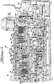
- the torque converter assembly 110 is operative to transmit power from a rotating crankshaft 114 of a prime mover such as an automobile engine (not shown) to the input member of the transmission 100. This power may then be subsequently transmitted to a drive unit 104 (partially shown) which is connected to one or more drive wheels (not shown) of the vehicle.
- the torque converter 110 is generally comprised of an impeller assembly 126, turbine assembly 128 and a stator assembly 130.
- the impeller assembly 126 is fluidly connected in toroidal flow relationship in a known manner with the turbine assembly 128 and the stator assembly 130.
- Stator plate 152 is mounted on a one-way or over-running clutch assembly, generally indicated at 154.
- the over-running clutch assembly 154 permits rotation only in the direction of the impeller assembly 126.
- the torque converter 110 also includes a lock-up clutch assembly, generally indicated at 186, to prevent slip between the rotating crankshaft 114 of the engine and the turbine assembly 128 of the torque converter 110.
- a fixed positive displacement pump assembly 200 includes a pump housing 202.
- An outer gear or rotor 218 with internal teeth operates within a bore 220 of the pump housing 202.
- a multi-clutch assembly 300 referred to as assembly of friction elements in the claims provides a means for application and release of two separate members to and from each other.
- the multi-clutch assembly 300 is the means by which the gears within the transmission are selectively engaged and disengaged from either the crankshaft 114 of the prime mover or the transmission case 102.
- the multi-clutch assembly 300 Near the input side of the transmission 100, the multi-clutch assembly 300 includes an underdrive clutch 302 (applied in first, second and third gears), overdrive clutch 304 (applied in third and fourth gears) and a reverse clutch 306 (applied in reverse gear) assemblies.
- the multi-clutch assembly 300 includes a two/four shift clutch assembly 308 (applied in second and fourth gears), and a low/reverse clutch assembly 310 (applied in first and reverse gears).
- an input clutch retainer hub 312 is provided to house the input clutch assemblies 302, 304 and 306.
- the input clutch retainer hub 312 has teeth 319 at its outer periphery.
- a turbine speed sensor 320 has one end 324 disposed or spaced radially just above the teeth 319 of the input clutch retainer hub 312.
- the turbine speed sensor 320 is used to monitor or sense the revolution rate of the turbine assembly 128 by counting the teeth 319 passing thereby in relation to time.
- a passive type speed sensor is used for the turbine speed sensor 320.
- suitable speed sensors could be employed within or before the transmission 100 to provide an input speed signal for a transmission controller 3010 in the claims referred to as electronic controller to be described in connection with Figures 3A-3G.
- the underdrive clutch assembly 302 comprises a plurality of axially spaced annular clutch plates 342 and a plurality of axially spaced annular clutch discs 344.
- the clutch discs 344 are alternated between the clutch plates 342 and when the clutch assembly 302 is not applied, these plates and discs are free to move or rotate relative to each other.
- the clutch plates 342 have splines (not shown) on their outer diameter and mount in grooves 346 of clutch retainer fingers 341 which are inside the input clutch retainer 326.
- the clutch discs 344 have internal splines (not shown) and are lined with a friction material 347.
- the clutch discs 344 are mounted in grooves 348 in an underdrive clutch hub 350.
- the underdrive clutch hub 350 is integral with a rotatable underdrive gear shaft 352 of the gear assembly 500.
- a thrust bearing 353 is disposed axially between the axially extending portion 314 of the input clutch retainer hub 312 and underdrive clutch hub 350.
- the overdrive clutch assembly 304 comprises a plurality of axially spaced annular clutch plates 354 and a plurality of axially spaced annular clutch discs 356.
- the clutch plates 354 and clutch discs 356 are similar to those of the underdrive clutch assembly 302.
- Clutch discs 356 are disposed in splines formed in an overdrive clutch hub 358 which is supported by bushings 360 and 361 about the gear shaft 352.
- Thrust members 362 and 363 are disposed axially between the underdrive clutch hub 350 and overdrive clutch hub 358.
- the thrust members 362 and 363 are similar to the thrust member within the torque converter.
- An annular reaction plate 364 is secured to the inside of the input clutch retainer 326 axially between the underdrive and overdrive clutch plates and discs 342, 344 354 and 356, respectively.
- the reaction plate 364 is shared by the underdrive 302 and overdrive 304 clutch assemblies.
- Annular snap rings 366 and 368 are disposed on the sides of the reaction plate 364. Snap ring 368 is a tapered ring, restraining reaction plate 364 from axial movement.
- the reverse clutch assembly 306 comprises at least one annular clutch plate 370 and a plurality of axially spaced annular clutch discs 372.
- the reverse clutch plate 370 and clutch discs 372 are similar to those of the underdrive clutch assembly 302.
- the reverse clutch discs 372 are mounted in splines 373 of a reverse clutch hub 374.
- the reverse clutch hub 374 is supported by bushings 376 and 378 about one end of the overdrive clutch hub 358.
- a thrust member 379 is disposed axially between the overdrive clutch hub 358 and reverse clutch hub 379.
- the thrust member 379 is similar to the thrust member within the torque converter.
- An annular reaction plate 380 is mounted about one end of the flange 340 of the input clutch retainer 326 on one side of the reverse clutch plate 370 and discs 372.
- Selective snap rings 384 secure the reaction plate 380 from axial movement along the input clutch retainer 326.
- a fluid actuating device such as a first hydraulic piston 386 has an axially extending projection 388 which operates in a bore or recess 390 of the input clutch retainer hub 312.
- the first hydraulic piston 386 includes an axially extending cylinder portion 406 which has an annular pressure plate member 408 secured at one end thereof by waved snap ring 409a and snap ring 409b.
- the pressure plate member 408 is interposed between the overdrive clutch assembly 304 and the reverse clutch assembly 306 to engage the clutch plates 354, 370 and discs 356, 372, respectively.
- the single pressure plate member 408 is shared by the overdrive clutch 304 and reverse clutch 306 assemblies.
- a second hydraulic piston 410 operates in a recess 412 of the input clutch retainer 326.
- the smooth outer diameter of the hub portion 314 of the input clutch retainer hub 312 has a groove 414 provided with a sealing means such as a synthetic rubber inner seal ring 416, while the outer periphery of recess 412 has a groove 418 for an outer seal ring 420.
- the second hydraulic piston 410 has one end 422 abutting the clutch plates 342 of the underdrive clutch assembly 302.
- An annular conically shaped spring retainer member 424 is abuttingly mounted against a snap ring 426.
- the snap ring 426 is disposed in a groove 428 formed in the axially extending portion 314 of the input clutch retainer hub 312.
- the other end of the spring retainer member 424 is in sealing engagement with the second hydraulic piston 410 through sealing means 430.
- the spring retainer member 424 is filled with fluid fed through an orifice (not shown) in the second hydraulic piston 410 from a passage (not shown) in the input clutch retainer hub 312 to provide the pressure balance for the second hydraulic piston 410.
- the excess fluid is allowed to leak past the snap ring 426 to cool the underdrive clutch assembly 302.
- a spring means such as a coiled spring 432 is disposed between the spring retainer member 424 and the second hydraulic piston 410 to bias or return the second hydraulic piston 410 to its original position shown in the figure when not applied.
- transmission case 102 houses the output or brake clutch assemblies such as the two/four shift clutch assembly 308 and the low/reverse clutch assembly 310.
- the two/four shift clutch assembly 308 comprises a plurality of axially spaced annular clutch plates 434 and a plurality of axially spaced annular clutch discs 436.
- the clutch plates 434 and clutch discs 436 are similar to those of the underdrive clutch assembly 302.
- the clutch plates 434 are mounted in splines 438 of circumferentially spaced and radially inwardly extending case clutch fingers 439 inside the transmission case 102.
- the clutch discs 436 are mounted in splines 440 formed in an axially extending flange 442 of the reverse clutch hub 374.
- a spring means such as a Belleville like spring 444, similar to spring 404, is mounted inside the transmission case 102 on one side of the two/four shift clutch assembly 308.
- An annular reaction plate 445 is mounted on the other side of the two/four shift clutch assembly 308 and between the two/four shift clutch assembly 308 and the low/reverse clutch assembly 310.
- the reaction plate 445 is shared by the two/four shift clutch 308 and low/reverse clutch 310 assemblies.
- Snap rings 446 and 447 are mounted in the transmission case 102 on the sides of the reaction plate 445 to lock it in place.
- Snap ring 446 is a tapered ring, restraining reaction plate 445 from axial movement.
- a third hydraulic piston 448 operates in a cavity 450 formed by an annular piston housing 452.
- the piston housing 452 is secured to the transmission case 102 by suitable fastening (not shown).
- the smooth diameter of the third hydraulic piston 448 has a groove 454 formed in its outer periphery for an outer seal ring 456 and a groove 458 formed in its inner periphery for an inner seal ring 460.
- a snap ring 462 is disposed in a groove 464 in the transmission case 102 to prevent axial movement of the piston housing 452.
- the low/reverse clutch assembly 310 comprises a plurality of axially spaced annular clutch plates 466 and a plurality of axially spaced annular clutch discs 468.
- the clutch plates 466 and clutch discs 468 are similar to those of the underdrive clutch assembly 302.
- the clutch plates 466 are mounted in splines 470 of the case clutch fingers 439 inside the transmission case 102.
- the clutch discs 468 are mounted in splines 472 of the outer periphery of an annulus gear 542 of the gear assembly 500 to be described further herein.
- a fourth hydraulic piston 474 operates in a cavity 476 formed by an annular piston housing 478.
- the piston housing 478 is disposed in an annular recess 480 of the transmission case 102 and secured by suitable fastening means, such as bolts 481, to the transmission case 102.
- the smooth diameter of the fourth hydraulic piston 474 has a groove 482 formed in its outer periphery for an outer seal ring 484 and a groove 486 formed in its inner periphery for an inner seal ring 488.
- a spring means such as a Belleville like spring 490, similar to spring 404, is disposed between the fourth hydraulic piston 474 and the gear assembly 500 to bias or return the fourth hydraulic piston 474 to its original position when not applied as shown in the figure.
- a snap ring 492 retains one end of the spring 490 to the transmission case 102.
- a gear assembly 500 referred to as a plurality of gears in the claims changes the ratio of torque between an input member, such as input shaft 176, and an output member, such us output gear 534 which will be further described herein.
- the gear assembly 500 comprises a front or first planetary gear set, generally indicated at 502, and an axially spaced rear or second planetary gear set, generally indicated at 504.
- the first planetary gear set 502 includes a first sun gear 506 at its center.
- the first sun gear 506 is connected to the reverse clutch hub 374 at its inner periphery and is supported upon bushings 376 and 378.
- a first planet carrier 508 is disposed about the first sun gear 506.
- the first planet carrier 508 includes a plurality of circumferentially spaced first pinion gears 510 mounted about shafts 512 connected to the first planet carrier 508.
- the first planet carrier 508 includes an inner portion 514 splined at 516 to the overdrive clutch hub 358.
- a thrust bearing 517 is disposed axially between one end of the first sun gear 506 and inner portion 514 of the first planet carrier 508.
- the first planet carrier 508 also includes an axially extending outer portion 518 forming a cylinder about the first planetary gear set 502.
- a first annulus gear 519 is disposed about the first planet carrier 508 and engages the first pinion gears 510.
- the rear or second planetary gear set 504 includes a second sun gear 520 at its center which is splined at 522 to the gear shaft 352.
- a thrust bearing 523 is axially disposed between one end of the inner portion 514 of the first planet carrier 508 and the second sun gear 520.
- a second planet carrier 524 is disposed about the second sun gear 520.
- the second planet carrier 524 includes a plurality of circumferentially spaced second pinion gears 526 mounted about shafts 528 connected to the second planet carrier 524.
- the second planet carrier 524 includes an inner portion 530 splined at 532 to a rotatable output gear 534 which acts as the output member of the transmission 100.
- the inner portion 530 of the second planet carrier 524 is supported by a bushing 536 disposed about the second sun gear 520.
- a thrust bearing 537 is disposed axially between the second sun gear 520 and second planet carrier 524.
- a tapered roller bearing assembly 538 supports the inner portion 530 of the second planet carrier 524 within the transmission case 102.
- the second planet carrier 524 also includes an outer portion 540 connected to the first annulus gear 519.
- the second annulus gear 542 is disposed about the second planet carrier 524 and engages the second pinion gears 526.
- the second annulus gear 542 is connected to the outer portion 518 of the first planet carrier 508.
- the second planet carrier 524 includes teeth 544 at its outer periphery of the outer portion 540.
- An output speed sensor 546 threadably engages a bore 548 in the transmission case 102 and has one end 550 disposed or radially spaced just above the teeth 544 of the second planet carrier 524.
- the output speed sensor 546 is used to monitor or sense the revolution rate (per minute) of the second planet carrier 524 by counting or sensing the teeth 544 passing thereby relative to time.
- the output speed sensor 546 is similar to the turbine speed sensor 320. It should also be noted that other suitable speed sensors could be used inside or after the transmission 100 to provide an output speed signal to the transmission's controller 3010.
- the output gear 534 is secured to the second planet carrier 524 by suitable fastening means such as a bolt 552.
- the output gear 534 is supported by a tapered roller bearing assembly 554 within the transmission case 102.
- a rear cover plate member 556 is connected by suitable fastening means (not shown) to the rear or output end of the transmission case 102 to enclose the output gear 534 and the transfer gear (not shown).
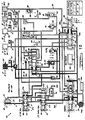
- FIG. 1D a schematic diagram of the hydraulic system 600 for controlling and operating the fluid flow throughout the transmission 100 is shown.
- the pump assembly 200, clutch assemblies 302, 304, 306, 308 and 310, torque converter assembly 110 of Figure 1, and valves to be described herein, are connected by a plurality of internal passageways, generally indicated at 602, in or between the valve body 603, transfer plate (not shown) and transmission case 102.
- the fluid source of the transmission 100 is the fluid contained in transmission pan (not shown) which acts as a reservoir.
- a filter 605 is attached to the lower half of a transfer plate at the inlet of the transfer plate to prevent dirt and other foreign matter from entering the hydraulic system 600.
- Another filter (not shown) is disposed in the valve body 603 at the pump pressure inlet to a pressure regulator valve 608 to protect a pressure regulator valve 608 from any loose chips and dirt in the pump hydraulic circuit.
- the pump assembly 200 is also connected by the passageways 602 to a manual valve 604 which is coupled to a manually actuated shift lever or manual shaft.
- the manual shaft is connected to a manual lever, its shift lever position PRNODDL being generally indicated by numeral 606.
- the pump assembly 200 is further connected by passageways 602 to a pressure regulator valve 608 and to a solenoid or fluid switch valve 610.
- the passageways 602 also connect the pressure regulator 608 to a cooler or torque converter (T/C) control valve 612.
- T/C cooler or torque converter
- the passageways 602 also connect the T/C control valve 612 to a lock-up (LU) switch valve 614.
- the passageways 602 further connect the LU switch valve 614 to the torque converter 110, and they also provide a path from the torque converter 110 back to the LU switch valve 614 and to T/C control valve 612.
- a cooler 616 is connected by passageways 602 to the T/C control valve 612.
- the manual valve 604 is also connected by passageways 602 to an underdrive element or clutch apply cavity 618, an overdrive clutch apply cavity 620, reverse clutch apply cavity 622 and a two/four shift clutch apply cavity 624.
- a low/reverse clutch apply cavity 626 is connected by passageways 602 to the solenoid switch valve 610 and, in turn, to the manual valve 604.
- the clutch apply cavities 618, 620, 622, 624 and 626 are also identified in Figures 1B and 1D.
- the valves 604 and 610 are also connected by passageways 602 to a vent reservoir 628 in the manifold assembly 700 which is at a higher elevation than the sump or fluid reservoir in the transmission pan. The other valves vent to the sump as indicated by the letter "V".
- the hydraulic system 600 also includes an underdrive element or clutch solenoid-actuated valve 630, overdrive clutch solenoid-actuated valve 632, two/four shift clutch solenoid-actuated valve 634 and low/reverse clutch solenoid-actuated valve 636 which are shown in Figure 1D.
- the solenoid-actuated valves 630, 632, 634 and 636 control the fluid flow to their respective clutch apply cavities 618, 620, 624 and 626.
- the manual valve 604 controls the fluid flow to the reverse clutch apply cavity 622.
- the low/reverse clutch solenoid-actuated valve 636 includes a second or dual function of controlling fluid flow to the LU switch valve 614 during lock-up of the torque converter 110.
- the two/four clutch solenoid-actuated valve 634 also has a dual function of controlling fluid flow to the low/reverse clutch apply cavity 626 when the shift lever position 606 is reverse.
- These solenoid-actuated valves 630, 632, 634 and 636 operate in response to command or control signals from the electronic controller.
- both the underdrive clutch solenoid-actuated valve 630 and two/four shift clutch solenoid-actuated valve 634 are designed to be normally applied. This means that in the absence of electrical power, the solenoid-actuated valves 630 and 634 will allow pressure or fluid flow in the passageways 602 to be transmitted to the underdrive clutch apply cavity 618 and two/four shift clutch apply cavity 624, respectively. Hence, the underdrive clutch assembly 302 and two/four shift clutch assembly 308 will be applied, resulting in the transmission 100 operating in second gear. Likewise, the overdrive clutch solenoid-actuated valve 632 and low/reverse clutch solenoid-actuated valve 636 are designed to be normally vented.
- the hydraulic system 600 also includes accumulators 638, 640, 642 and 644 which are connected to passageways 602 before the underdrive 618, overdrive 620, two/four shift 624 and low/reverse 626 clutch apply cavities, respectively.
- the accumulators 638, 640, 642 and 644 comprise a first spring 645a, a second spring 645b and a piston 645c operating in a bore 645d in the valve body 603.
- the purpose of these accumulators 638, 640, 642 and 644 is to absorb the fluid apply pressure to help cushion the application of the underdrive 302, overdrive 304, two/four shift 308 and low/reverse 310 clutch assemblies, respectively.
- Pressure switches 646, 648 and 650 are connected to the passageways 602 which lead to the overdrive clutch apply cavity 620, the two/four shift clutch apply cavity 622 and the low/reverse clutch apply cavity 626, respectively.
- the pressure switches 646, 648 and 650 provide a digital electrical signal of zero (0) value when there is either an absence of fluid pressure or fluid pressure below a predetermined pressure, and a value of one (1) when there is fluid pressure present at or above a predetermined pressure in the passageway 602 leading to the respective clutch apply cavities 620, 624 and 626.
- suitable pressure sensors may be employed in these or other locations in the appropriate application.
- the hydraulic system 600 also includes first 652, second 654, third 656, fourth 658 and fifth 660 ball check valves in the passageways 602 leading to the low/reverse 626, underdrive 618, low/reverse 626, reverse 622 and overdrive 620 clutch apply cavities, respectively.
- the ball check valves 652, 654, 656, 658 and 660 comprise a rubber ball operating against a seat, typically formed in the valve body 603, and are used for flow control to open and close particular passageways 602. The ball is seated by pressure acting against the ball and unseated by pressure being applied on the opposite or seat side of the ball.
- the LU switch valve 614, T/C control valve 612 and pressure regulator 608 include springs 662, 664 and 666, respectively, at one end to preload these valves.
- a thermal valve 668 is also provided to regulate the fluid flow through check valve 654 at higher fluid temperatures. The thermal valve 668 closes or opens a particular passageway 602 based on the fluid temperature.
- the adaptive control system 3000 includes a transmission controller 3010 which is capable of both receiving signals from an engine controller 3020 and transmitting signals to this engine controller 3020. While the transmission controller 3010 may be readily adapted to operate without an electronic engine controller, the transmission controller 3010 according to the present embodiment takes advantage of the fact that most automobiles today include a digital or computer based engine controller which receives and processes signals from numerous sensors. For example, Figure 2A shows that both the transmission controller 3010 and the engine controller 3020 receive an input signal indicative of the temperature of the engine (e.g., the coolant temperature).
- exemplary input signals shared by these controllers include one or more signals from the ignition switch, a battery voltage level signal, and a signal from the distributor or other firing angle control mechanism.
- this controller will process such signals and transmit appropriate control or command signals to various components of the engine.
- Typical computer based engine controllers will also generate and transmit advisory signals to a diagnostic alert panel in the passenger compartment to provide a visual and/or auditory indication of particular engine conditions.
- the transmission controller 3010 includes the capability of communicating with existing engine controllers. For example, it may be advisable for the transmission controller 3010 to send signals to the engine controller 3020, such as a signal indicating that the transmission 100 is about to shift gears. As will be appreciated from the description below, the transmission controller 3010 is preferably provided with a serial communications interface to permit serial data transfers to be made between the transmission controller 3010 and the engine controller 3020. Additionally, the transmission controller 3010 may also provide diagnostic alert capabilities, such as transmitting suitable advisory signals to the vehicle operator (e.g., "check transmission").
- a throttle sensor 3030 may be any suitable sensor which will give an indication of the power demand placed upon the engine by the vehicle operator, such as a transducer which will indicate the present position of the throttle.
- the brake switch 3040 may be any suitable sensor which will give an indication of the application of the vehicle brake by the operator, such as a contact switch actuated by the movement of the brake pedal in the vehicle.
- the transmission controller 3010 includes suitable interface circuits for receiving signals from the throttle sensor 3030 and the brake switch 3040. Further examples of information shared between the controllers are signals concerning vehicle type, engine type, manifold absolute pressure (MAP) and load.
- MAP manifold absolute pressure
- One of the primary functions of the transmission controller 3010 is to generate command or control signals for transmission 100 to the solenoid-actuated valves 630, 632, 634, 636 contained in the hydraulic system 600 ( Figure 1D) of the transmission 100.
- these solenoid-actuated valves are lumped into a solenoid block 3050 which is contained within a dashed block labeled "Transmission”.
- This Transmission block represents a suitable transmission structure which will operate in conjunction with the transmission controller 3010, such as the transmission 100 described above.
- the solenoid block 3050 would comprise the solenoid-actuated valves 630, 632, 634 and 636.
- the hydraulic controls block 3060 would comprise other valves contained in the hydraulic system 600, such as the pressure regulator valve 608, the manual valve 604, the T/C control valve 612 and so forth, as described above.
- the friction elements gear box block 3070 would comprise the multi-clutch assembly 300 and the gear assembly 500 as described above.
- the adaptive control system 3000 according to the present invention may be used in conjunction with other suitable transmission structures in the appropriate application.
- Figure 2 A also illustrates that the Transmission block includes a PRNODDL sensor block 3080 which is responsive to a gear shift lever that is under operator control.
- the PRNODDL sensor block 3080 may be comprised of one or more suitable sensors which are capable of providing an indication to the transmission controller 3010 of the transmission operating mode selected through the manual actuation of the gear shift lever.
- Two contact switch sensors NS1 and NS2 are mounted to the transmission case 102.
- the sensors NS1 and NS2 are mounted in proximity to the manual lever in order to permit a spring loaded pin of these sensors to engage and follow the peripheral track of a cap member of the manual lever.
- the transmission controller 3010 receives input signals from the PRNODDL sensor block 3080, as well as produces output signals to a PRNODDL indicator contained in the passenger compartment.
- This PRNODDL indicator may, for example, be a suitable light source or other appropriate indicator for providing the operator with a visual indication of the operating mode which has been selected.
- Figure 2 A also indicates that a pressure switch block 3090 is connected to the hydraulic controls block 3060.
- the pressure switch block 3090 would comprise the pressure switches 646, 648 and 650 ( Figure 1D).
- each of these pressure switches is adapted to provide a signal indicative of a predetermined pressure level in the corresponding passageways leading to selected friction elements.
- each of these pressure switches provide a digital input signal to the transmission controller 3010 which will indicate whether or not this pressure level has been reached.
- the Transmission block includes a speed sensors block 3100 which is connected to the friction elements gear box 3070.
- the speed sensors block 3100 comprises the input or turbine speed sensor 320 and the output speed sensor 546 which are both mounted to the transmission case 102.
- other suitable speed sensor means may be provided either within or outside of the transmission case 102 in order to provide the desired input or turbine and output speed signals to the transmission controller 3010.
- the speed sensors block 3100 may also include a suitable engine speed sensor (e.g., hall effect device). However, if the engine controller 3020 is already receiving such a speed signal, then this signal could be shared with the transmission controller 3010 to avoid unnecessary duplication.
- the first block is the serial communication interface 3200 which has as its function to provide a serial communications link with the engine controller 3020.
- This serial communication interface 3200 could also be used to provide a serial communication link with other appropriate microcomputer-based controllers in the vehicle. It should also be understood that a parallel communication could also be used in the appropriate applications.
- the serial communications interface 3200 utilizes the multiplexing protocol and interface technology of the Chrysler Collision Detection ("C
- D Chrysler Collision Detection
- This technology is described in the co-assigned U.S. Patent No. 4,706,082, entitled “Serial Data Bus For Intermodule Data Communications," and U.S. Patent No. 4,719,458, entitled “Method Of Data Arbitration And Collision Detection In A Data Bus," and U.S. Patent No. 4,739,323, entitled “Serial Data Bus For Serial Communication Interface (SCI), Serial Peripheral Interface (SPI) and Buffered SPI Modes of Operation,” and U.S. Patent No.
- serial communications interface 3200 Another function for the serial communications interface 3200 is to provide a diagnostic interface with the transmission controller 3010 so that service information can be provided to a technician as a troubleshooting or maintenance aid. Still another function of the serial communications interface 3200 is to provide a convenient data or program access route for in-plant testing of the transmission controller 3010 during the manufacturing process.
- the transmission controller 3010 also includes several other interface circuits which are used to receive and condition input signals from the various sensors identified above.
- the transmission controller 3010 includes a block 3210 which contains the interface circuits used to receive signals from the speed sensors 3100 and the throttle sensor 3030.
- the transmission input speed signal represents the turbine speed N t of the torque converter 110, while the output speed signal represents the output speed N o of the vehicle.
- both of these signals are generated by variable reluctance pick-ups (e.g., speed sensors 320 and 546).
- the engine speed is also sensed by a suitable sensor, such as a hall effect pick-up in the distributor of the engine. This technology is described in co-assigned U.S. Patent No. 4,602,603, entitled "Ignition Distributor-Hall Effect Sensor Switching System and Method ".
- block 3210 The function of block 3210 is to provide input signal conditioning, filtering and conversion of the speed sensor signals to digital logic levels.
- block 3210 also includes an interface circuit for the throttle position sensor 3030. Once this signal is properly conditioned, this information may be shared with the engine controller 3020.
- the throttle position sensor 3030 will give an indication as to which angular position the throttle blade (means) is in within the throttle body.
- the throttle position sensor signal is conditioned and fed through a unity gain differential amplifier to provide isolation, as will be described below.
- the transmission controller 3010 also includes blocks 3220 and 3230 which represents the interface circuits used to receive various input signals related to the engine ignition and PRNODDL condition.
- the ignition related signals include a signal J2, and a signal S2.
- the signals related to the PRNODDL condition include the "neutral start” signal NS1, and “auxiliary neutral start” signal NS2, a "first reverse light” signal RL1 and a “second reverse light” signal RL2.
- the control methodology is responsive to the condition that these ignition switch voltage signals are in. The reason for this is that it is appropriate to hold the transmission controller 3010 in certain predetermined conditions depending on the position of the ignition switch and/or the neutral contact switch sensor NS1 and/or the auxiliary contact switch sensor NS2.
- the signal J2 represents the ignition voltage during the run and crank positions, and this signal will generally be either at a zero voltage level or at the battery voltage level.
- the signal S2 represents the voltage in the crank position only and is used to provide the necessary voltage for the starter relay coil of the engine. To determine when the transmission 100 is in a crank condition the NS1 or neutral start switch signal is sensed along with the S2 signal to hold the transmission controller 3010 in a reset condition during cranking due to the possibility that the battery voltage may drop below level required for proper controller operation.
- the PRNODDL condition switches provide input signals from the contact switch sensor NS1, the auxiliary contact switch sensor NS2, the first reverse light RL1 and the second reverse light RL2.
- the PRNODDL switch block 3230 controls the switching of the reverse lights which are connected in series.
- electrical current from the ignition switch J2 is fed through a relay coil which interconnects the reverse lights to battery voltage via the relay contacts thus turning on the backup lights on the vehicle.
- the PRNODDL switch block also acts in combination with the two contact switch sensors NS1 and NS2 to determine the shift lever position, as discussed above.
- the transmission controller 3010 includes a pressure switch block 3240 which represents the interface circuit used for receiving and conditioning the pressure level signals from the pressure switches 3090.
- Each of the pressure switches provide a digital level signal which is either at a zero or battery voltage level depending upon whether or not a predetermined pressure level has been reached.
- the pressure switches are used in conjunction with the low/reverse, overdrive and two/four shift (kickdown) clutch assemblies, and generally comprise grounding switches located in a manifold assembly.
- the pressure switch interface circuit 3240 provides input signal conditioning, i.e. filtering and buffering for these signals. For example, pull up resistors located in the manifold assembly to provide battery voltage when pressure switch is open are contained in block 3090.
- the state of each of the pressure switch signals is transmitted to the transmission controller 3010 to provide feedback information for use in both monitoring clutch operation and as an input to the learning logic and methodology described herein.
- the heart of the transmission controller 3010 is contained in the micro core block 3250.
- the micro core 3250 includes an eight-bit microcomputer unit (MCU), a memory chip for storing the application or operating program used by the MCU, and an interface chip for addressing and routing signals on the various lines used in the micro core bus structure.
- MCU microcomputer unit
- the interface chip for addressing and routing signals on the various lines used in the micro core bus structure.
- several of the signals received from the controller's interface circuits are connected to the interface chip, which will then place these signals on the data bus when the chip is properly addressed by the MCU.
- the transmission controller 3010 also includes a watchdog/reset block 3260 which provides several circuit functions in conjunction with the micro core 3250.
- the watchdog/reset circuits 3260 will control the initial start up of the MCU, watch to see if the MCU is properly functioning, cause a reset of the MCU in response to certain regulator voltage conditions, and provide a frequency divider for the speed signals.
- the watchdog/reset circuits 3260 also provide an output to a relay driver block 3270 which is used to disconnect or turn off electrical power to the solenoid-actuated valves 630, 632, 634 and 636 in the solenoid block 3050 shown in Figure 2 A under predetermined conditions.
- the solenoid driver block includes a separate driver circuit for the solenoid-actuated valves 630, 632, 634 and 636 contained in the solenoid block 3050 shown in Figure 2 A. These driver circuits generate the electrical current necessary to operate the solenoid- actuated valves 630, 632, 634 and 636 in response to the control signals generated by the MCU.
- the solenoid driver block 3280 also includes spike monitor circuits which verify the operation of the solenoid driver circuits by detecting the presence of an inductive spike which occurs when the solenoid coil is de-energized.
- the transmission controller 3010 also includes a regulator block 3290 and a test mode block 3300.
- the regulator block 3290 is used to advise the watchdog/reset circuit 3260 of predetermined conditions relating to the operation of the regulator, such as a low battery voltage condition, a high battery voltage condition, an overload condition, or an over temperature condition in the regulator. It is a dual regulator and includes a 5V, switched output.
- the test mode block 3300 is used to permit a test mode program to be downloaded into the RAM memory of the MCU for testing the transmission system.
- Figures 3A-3G a schematic diagram of the transmission controller 3010 is shown.
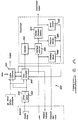
- Each of the Figures 3A-3G generally correspond to one of the circuit blocks shown in Figure 2 B.
- Figure 3A illustrates the serial communication interface 3200 which provides a serial communication link between the transmission controller 3010 and the engine controller 3020.
- Figure 3B illustrates the MCU chip Z138 and the interface chip Z135 which form part of the micro core 3250.
- Figure 3C which illustrates the EPROM chip Z141 and its associated circuitry.
- Figure 3C illustrates a watchdog/reset chip Z127 and associated circuitry, which together correspond to the watchdog/reset circuit 3260. A discussion of the circuits contained in the watchdog/reset chip Z127 will be presented in connection with Figure 4.
- Figure 3D illustrates the speed and throttle input interface circuits 3210.
- Figure 3E illustrates the PRNODDL interface circuits 3230 and part of the ignition switch interface circuits 3220.
- Figure 3F illustrates the regulator circuit 3290 and the relay driver circuits 3270.
- Figure 3G illustrates the solenoid driver circuits 3280.
- FIG. 3A a schematic diagram of the serial communications interface 3200 is shown.
- This communications interface actually provides for two serial communication channels for the transmission controller 3010.
- the first serial communication channel 3201 is based upon the Chrysler Collision Detection (C
- D Chrysler Collision Detection
- This technology is embodied in the communications chip Z14 which provides the intelligence to know when it has sent a message out onto a serial data bus and whether or not it has won access to the bus.
- This bus comprises the two conductors labeled "(C
- this serial communications bus comprises a double ended or differential signal transmission link with the engine controller 3020 (or any other appropriate controller in the vehicle which is connected to the bus structure).
- the communications chip Z14 receives signals transmitted from the microcomputer chip Z138 (shown in Figure 3B) via its connection to the "PD3" port of the microcomputer. Similarly, signals are transmitted from the communications chip Z14 to the microcomputer chip Z138 via the "PD2" port.
- the communications chip Z14 is provided with a clock signal "E**" which is derived from the MCU chip's Z138 system clock, namely the "E” Clock. As shown in Figure 3C, two NAND gates Z195 are connected in series to double buffer and double invert the E clock signal. Signal transmissions from the MCU chip Z138 are initiated by the MCU chip Z138 which pulls down a "Control" line of communications chip Z14 via a command signal transmitted from the "PD5" port. However, the communications chip Z14 will actually control the transfer of data from the MCU chip Z138 by providing a "SCLK” clock signal to the MCU's "PD4" port, which will clock the data in and out of the MCU chip.
- the communications chip Z14 is turned off when the transmission controller 3010 is in a stop mode, such as after the ignition key is turned off.
- the communications chip Z14 is turned off through the "SW/5V" power supply.
- the SW/5V voltage level is derived from a dual regulator Z215 contained in the regulator circuit 3290 shown in Figure 3F. Specifically, the SW/5V supply is switched on or enabled by the MCU Z138 in response to the ignition switch
- FIG. 3A also illustrates the second serial communications channel which is generally designated by the reference numeral 3202.
- the serial communications channel 3202 is generally comprised of a transmit line labeled "SCI-XMT" and a receive line labeled "SCI-REC". Each of these transmit and receive lines include an RC filter and a buffering inverter Z15.
- the transmit line SCI-XMT is connected to the "PD1" port of the microcomputer chip Z138, while the receive line SCI-REC is connected to the "PD0 ⁇ " port of the microcomputer chip.
- This second serial communications channel may be used for example to download appropriate test programs into the microcomputer chip Z138, such as for end of line testing at the manufacturing facility.
- the SCI-REC receive line is used in conjunction with the test mode to transmit a signal to the microcomputer chip Z138 which will cause a ROM resident boot load program inside the microcomputer chip to control the receipt and initial execution of the test programs.
- the micro core 3250 for the transmission controller 3010 generally comprises the microcomputer 3251 (chip Z138), the interface 3252 (chip Z135), and the memory 3253 (chip Z141).
- the microcomputer chip Z138 is a Motorola eight-bit microcomputer chip (Part No. 68HC11), which includes 256 bytes of RAM memory and 512 bytes of EPROM (erasable electrically programmable read only memory).
- 68HC11 Motorola eight-bit microcomputer chip
- EPROM erasable electrically programmable read only memory
- the memory 3253 (chip Z141) may be any suitable memory chip or circuit having sufficient capability to store the computer programs which operate in accordance with the control methodology discussed in detail above.
- the interface 3252 may be any suitable chip or set of chips/circuits.
- the interface 3252 includes several internal registers for facilitating rapid communications between microcomputer 3251 (chip Z138) and several of the other circuits contained in the transmission controller 3010, such as the pressure switch interface circuit 3240.
- the various circuits have been combined into a single chip configuration, namely interface (chip Z135), to conserve space on the circuit board for the transmission controller 3010.
- each of the pins or ports of the various chips used in the micro core 3250 have been appropriately labeled, so that the various circuit connections between these chips and the other circuits contained in the transmission controller 3010 may be readily discerned from each of the Figures 3A-3G.
- the "Control" and “Idle” lines of the communication chip Z14 in Figure 3A are also shown to be labeled “PA7” and "PD1" respectively.
- both of these signal lines are connected to the interface (chip Z135), as this chip contains both the "PA7” and "PB1" labeled ports.
- the microcomputer 3251 (chip Z138) and the interface 3252 (chip Z135) communicate with each other via an address/data bus labeled "AD0 ⁇ -AD7".
- the address/data lines in this bus are bidirectional to allow the transfer of both address and data information between the microcomputer 3251 (chip Z138) and the interface 3252 (chip Z135).
- the memory (chip Z141) is also connected to this address/data bus.
- the memory (chip Z141) is also connected to the microcomputer 3251 (chip Z138) via an address bus which is comprised of address lines "A8-A15". Three of these address lines, namely address lines A13-A15, are also connected to the interface 3252 (chip Z135) for selecting particular register or RAM locations within this chip.
- a schematic diagram of the speed and throttle input circuits 3210 are shown. These circuits are designated as 3212, 3214 and 3218.
- the speed input signals are labeled “N e /Turbo”, “N e “, “N o “ and “N t “.
- the throttle input signals are labeled “THD-GND” and "THR”.
- N e /Turbo and N e signals are used in an application involving a turbo equipped engine, which provides a dual pick-up in the distributor of the engine.
- both the NE and NE/Turbo signals are used to indicate engine speed.
- these signals are out of phase with each other.
- the input interface circuit for the N e /Turbo signal comprises a low pass filter 3212, which includes resistor R91 and capacitors C90 and C32.
- the filtered NE/Turbo signal is then directed to the "PB2" port of the interface 3252 (chip Z135).
- a similar filter network 3214 is also provided for the engine speed signal “N e ".
- an inverting amplifier Z15 is also included as a buffer to provide the fast rise and fall times required by the microcomputer 3251 (chip Z138), as well as noise immunity.
- the "N o " input signal represents the output speed of the transmission
- the "N t " signal represents the input or turbine speed of the transmission.
- These signals are first filtered and then transmitted to a zero crossing detector circuit which includes the comparator Z47. Due to the sensitivity of these signals (e.g., minimum amplitude of 500 millivolts peak to peak), each of the comparators Z47 is provided with a positive feedback loop for adding hysteresis capability to these zero crossing detector circuits. For example, resistor R49 and capacitor C48 provide this hysteresis capability for the output speed signal N o . It should also be noted that the filter circuits for these two speed signals use a ground signal labeled "A/GNB".
- This ground signal represents a clean ground signal which is derived from the microcomputer 3251 (chip Z138) to heighten the sensitivity of these filter circuits.
- the THR and TH-GND signals are used to indicate the throttle position in the vehicle. These signals are processed through a unity gain differential amplifier circuit, which is generally designated by the reference numeral 3216. This differential amplifier circuit is used to sense the ground potential of the throttle position sensor, as well as sense the potentiometer wiper signal of this sensor. The output of the differential amplifier circuit 3216 is directed to the "PE0 ⁇ " port of the microcomputer 3251 (chip Z138). Since the throttle position signal is an analog input signal, it should be appreciated that the microcomputer 3251 (chip Z138) includes an internal analog to digital converter to permit further processing of this signal in accordance with the control methodology discussed above.
- Dissimilar grounds can generate a variable reference to ground. This is a function of variable resistance and inductance in the vehicle and its electrical system.
- the variable ground reference could be a significant percentage of the span of the output voltage from the throttle position sensor. Therefore, without the feature of the shared throttle position sensor circuit, two sensors would be needed.
- Figure 3D also shows a portion of the ignition switch interface circuits 3220. Specifically, Figure 3D shows the interface circuit 3218 for the ignition switch signal "J2". The interface circuit 3218 provides a low pass filter whose output is directed to the "FJ2" port of the watchdog/reset chip Z127.
- the interface circuit 3222 includes a voltage divider (R78 and R80), a low pass filter (R61 and C79), and a comparator Z47.
- the voltage divider is used to decrease the voltage level of the S2 signal, so that it does not exceed the maximum input voltage of the comparator.
- the output of the comparator Z47 is connected to the "FS2*" port of the watchdog/reset chip Z127.
- the S2 ignition signal is used to hold the microcomputer 3251 (chip Z138) in a reset mode during the cranking of the engine. This provision is implemented for purposes of accuracy, since it is possible that the battery voltage in the vehicle could dip down during the cranking of the engine.
- Figure 3E also illustrates the PRNODDL interface circuits 3230. Specifically, Figure 3E shows the circuits used to interface the neutral start signals "NS1" and “NS2", as well as the circuits used to interface the reverse light signals “RL1" and "RL2". Each of these signals are digital signals which will generally be at a zero or battery voltage potential. Accordingly, each of the interface circuits for the signals include a pair of voltage dividing resistors (in addition to a filter) for getting the battery voltage level down to a 5 volt potential. In this regard, it should be noted that each of these input signals are coupled to the ignition switch signal "J2" through suitable pull-up resistors (e.g., R82 and R83) to ensure that these signals will provide battery voltage potential when their corresponding switches are open.
- suitable pull-up resistors e.g., R82 and R83
- the transistor Q93 is used to disable the S2 signal from causing a reset of the microcomputer 3251 (chip Z138). In other words, when the contact switch NS1 is open, the NS1 signal will be HIGH, thereby causing the transistor Q93 to conduct and pull down the input voltage to the comparator Z47. This provision is to ensure that the S2 signal does not cause a reset unless the transmission 100 is either in neutral or in park.
- FIG. 3F a schematic diagram of the regulator circuit 3290 and the relay driver circuit 3270 is shown. Additionally, Figure 3F shows two capacitors (C228-C233) which are used to tie the grounding potential of the circuit board for the transmission controller 3010 to the aluminum case which surrounds the circuit board. This optional feature may be used to provide additional RF or electromagnetic compatibility for the transmission controller circuitry.
- the regulator circuit 3290 shown in Figure 3F generally comprises a dual 5 volt regulator chip Z215 which receives a voltage input signal from the vehicle battery and a command signal from the watchdog/reset chip Z127.
- This command signal labeled "PSENA*”
- PSENA* is used to enable or switch on and off the "VO2" output of the regulator chip under MCU command when ignition is off.
- the VO2 output of this chip provides the "SW/5V" supply signal discussed above.
- This provision of a switchable 5 volt supply is particularly advantageous in a vehicle application, as it permits a substantial portion of the peripheral circuitry (or circuitry with a low priority) connected to the micro core 3250 to be shut down when the vehicle ignition is off thus reducing current draw on the battery.
- a continuous voltage output can be provided to high priority circuits such as a memory chip or a MCU. It can also be used to keep high priority circuits energized in a "KEY-OFF" situation, if desired, to allow for example the control of gear selection/display while the engine is off.
- the shutdown relay driver circuit 3270 includes a self protecting, high side switch chip Z219 which is responsive to a "RLYCNT" control signal from the watchdog/reset chip Z127. Specifically, the relay control signal will cause the battery voltage to be transmitted to the "VOUT" port of the switch chip Z219. This voltage output from the chip Z219 is referred to as the "RELAY/PWR” signal, as it provides the power necessary to operate the shut down relay 3272 shown in Figure 4.
- the shut down relay 3272 is used to cut power off to the solenoid driver circuits 3280 to thereby achieve a "LIMP-IN" mode previously described.
- the "SW/BATT" signal shown in Figure 3F will be transmitted to the solenoid driver circuits 3280.
- the conditioning circuit 3274 includes a diode "D224" which is used to clamp the back EMF of the solenoid coils when the shut down relay 3272 is open.
- the conditioning circuit 3274 also includes a pull down resistor R225 to ensure that the line is pulled to ground despite the states of the solenoid driver circuitry.
- a capacitor C223 is also provided to suppress any line inductive energy spikes that sight occur in response to the switching of the transmission solenoids.
- both the "RELAY/PWR” and “SW/BATT” signals provide input signals to conditioning circuit block.
- the conditioning circuit block employs thick film packaging technology to effectively create a single compact chip for the circuits contained in this block.
- the conditioning circuit block is comprised of four identical conditioning circuits. Each of these conditioning circuits include an RC filter (R300 and C200) and a pair of voltage dividing resistors (R301 and R302). Since the SW/BATT and RELAY/PWR signals are at the battery voltage potential, the voltage dividing resistors cut this voltage level down to the 5 volt logic level used in the micro core 3250.
- each of the conditioning circuits include a diode "D300" which connects the input signal of each of these circuits to the SW/5V supply line.
- D300 diode
- the regulator chip Z215 will actively pull the SW/5V signal level down to ground during an over voltage condition (e.g., where the battery voltage exceeds 30 volts). Accordingly, the diode D300 will clamp the battery voltage level input signals to the conditioning circuits down to ground during such an over voltage condition. This will prevent excessive input signals from being transmitted to the micro core circuits 3250 via ESD protection diodes.
- the RELAY/PWR signal is transmitted to the "PB0 ⁇ " port of the interface circuit Z135 of the micro core 3250 through the conditioning circuit.
- This feedback provision will enable the microcomputer 3251 (chip Z138) to confirm the status of the relay driver circuit 3270 and is also used while testing the watchdog reset.
- the solenoid driver circuits 3280 comprise an individual driver circuit for each of the four solenoid-actuated valves 630, 632, 634 and 636 contained in the transmission namely, driver circuits 3282-3288.
- Each of these driver circuits is provided with two input signals, one of which is derived from the interface 3252 (chip Z135) and the other of which is derived from the microcomputer 3251 (chip Z138).
- an enablement command signal is transmitted from "PC6" port of the interface 3252 (chip Z135), and a current control signal is transmitted from the "OC2" port of the microcomputer 3251 (chip Z138).
- the OC2 signal is derived from an internal timer of the microcomputer 3251 (chip Z138). Specifically, the OC2 control signal generated by MCU timer functions provides a series of pulses which have an appropriate duty cycle for causing a pulse width modulation of the current to the solenoid coil, such as the underdrive (UD) coil, in addition a "pull in” pulse is MCU timer generated when the solenoid coil is first turned on.
- the solenoid coil such as the underdrive (UD) coil
- the driver circuit 3282 When the microcomputer 3251 (chip Z138) causes the interface 3252 (chip Z135) to latch its "PC6" port into a HIGH state, the driver circuit 3282 will be enabled through the gating on of transistors Q177 and Q169. The gating on or HIGH pulse of the OC2 signal will permit the current in the UD solenoid coil to charge up through the transistor Q179. Then, when the pulse of the OC2 signal is turned off, current through the UD solenoid coil will circulate in the path created by the diode D168 and transistor Q169. The result will be an efficient slow decay of the current through the UD solenoid coil. At this point, it should be noted that the junction between the Darlington pair transistor Q169 and the MOSFET resistor Q179 will be at a potential above the potential of the SW/BATT supply signal.
- the transistor Q177 will switch off and cause a rapid decay of current through the UD solenoid coil.
- the gate signal is removed from the transistor Q177, it should be noted that the Darlington pair transistor Q169 will also turn off. This rapid decay of current will also cause the voltage on the conductor 3289 to rise above the SW/BATT potential. At some point (e.g., 25 volts), this rising potential will cause the Darlington pair transistor Q169 to turn on again to limit the spike of this rising voltage potential.
- the voltage potential on conductor 3289 is transmitted through the diode "D174" to the zener diode "D173".
- a predetermined potential e.g., 24 volts
- the zener diode D173 will breakdown and cause current to flow through the transistor Q168 to the "PB3" port of the interface 3252 (chip Z135).
- This spike monitor circuitry is an important aspect of the present invention, as it allows the microcomputer 3251 (chip Z135) to determine whether the solenoid coil is in a shorted or open condition. In other words, the spike monitor circuitry of the solenoid driver circuits 3280 will tell the microcomputer 3251 (chip Z138) that the solenoid coil has indeed turned off. In this regard, it should be noted that the SW/BATT signal continually keeps the transistor Q168 in a conducting condition, so that the current from conductor 3289 will pass directly through its emitter and collector junctions for transmission to the "PB3" port of the interface 3252 (chip Z135).
- diode “D173" is connected to each of the driver circuits 3282-3288 through appropriate diodes (e.g., D175 and D202), so that the microcomputer 3251 (chip Z138) will be able to detect the presence of a voltage spike from each of these driver circuits. While each of the driver circuits 3282 are substantially identical, the connections employed in the driver circuit 3282 will be briefly described.
- the OC2 port of the microcomputer 3251 (chip Z138) is connected to the gate of the MOSFET transistor Q179 through the resistor R161.
- the source of the transistor Q179 is connected to ground, while the drain of this transistor is connected to one end of the UD solenoid coil.
- the other end of the UD solenoid coil is connected to the junction between the SW/BATT potential and the diode pair D168.
- the common emitter junction of the Darlington pair transistor Q169 is connected across the reverse bias diode in the diode pair D168, while the collector junction of the transistor is connected to the drain of the MOSFET transistor Q179.
- a capacitor C248 is coupled across the collector and base junctions of the Darlington pair transistor Q169 for stability, while a resistor R298 is connected across the base and emitter junction of this transistor to provide sufficient current for spike monitor operation.
- the base of the transistor Q169 is also connected to the collector junction of the transistor Q177 through the resistor R178.
- the base of the transistor Q177 is coupled to the "PC6" port of the interface circuit Z135 through the transistor R176.
- the emitter junction of the transistor Q177 is connected to ground.
- the conductor 3289 is connected to the collector junction of the transistor Q177, and is coupled to the diode D174 through one of the diodes labeled "D175".
- FIG. 4 a block/schematic diagram of the watchdog/reset circuit Z127 is shown in association with some of the circuits connected to the watchdog/reset circuit Z127.
- the first function of the watchdog/reset or "WD" circuit is to monitor the operation of the microcomputer 3251 (chip Z138) by requiring the MCU to periodically transmit a signal to the WD circuit. This signal is designated “WDG” in both Figures 3C and 4. If the WD circuit does not receive the WDG signal within a predetermined time window, then the WD circuit will know that the MCU may not be functioning as desired. However, before the WD circuit will react to this situation, it will wait a predetermined amount of delay time to see if proper functioning of the MCU will be quickly restored. If the WDG signal is not received by the end of the delay period, then the WD circuit will transmit a "RLYCNT" signal to the relay driver circuit Z219 which will cause the shutdown relay 3272 to remove electrical power from the solenoid driver circuit 3280.
- the WD circuit includes a window detector circuit 3700 which receives the WDG signal.
- the window detector circuit 3700 includes an up counter which is reset by the WDG signal, and a pair of comparators which determine whether or not the WDG has been received within the predetermined time window (e.g., 14 ms.). If the WDG signal is received too early or too late, or not received at all, then the Q output of the window detector will switch to a LOW digital state. This will in turn drive the output of AND gate 3702 LOW.
- the output of the AND gate 3702 is connected to a fault delay circuit 3704 and to a conductor 3706.
- the fault delay circuit 3704 will give the MCU a predetermined time period (e.g. 64-512 ms.) to transmit the WD signal. This time period may be altered between four different values depending upon the particular voltage or ground connections for the input signals "DLYA” and "DLYB".
- the conductor 3706 will transmit the "WDFLT” feedback signal, and provide a way of separately testing the operation of the window detector 3700 and the fault delay circuit 3704 within the WD circuit.
- the conductor 3706 is connected to an input of the AND gate 3702 through the resistor 3708 and conductor 3710.
- the MCU will transmit the "DLY/MON” signal, which will drive the AND gate 3704 LOW in order to simulate the absence of the WD signal from the window detector circuit 3700.
- the AND gate 3712 will switch states, and cause the relay driver circuit Z219 to cut off power through the logic connections provided by OR gate 3714 and AND gate 3716.
- the AND gate 3712 also receives a "Latchdown" signal from the relay driver circuit, which will prevent the AND gate 3712 from switching states again until the reset start-up sequence is initiated, even if the MCU transmits a proper WDG signal in the intervening time period.
- the reset start up sequence must be initiated before power will be restored to the solenoid driver circuit.
- the WD circuit is also responsive to a master kill signal "MK" from the MCU for removing power from the solenoid driver circuit 3280.
- MK master kill signal
- Another function of the WD circuit Z127 is to control the reset start-up sequence which will occur, for example, when electrical power is first applied to the transmission controller 3010. When power is first applied, this sequence will be initiated by the master reset signal "MRST", which is derived from an RC delay off the VDD power supply.
- MRST master reset signal
- the reset start-up sequence may also be initiated from a filtered door entry signal "FENTRY”. This optional feature could be provided when it is desired, for example, to have the vehicle electrically display the current PRNODDL transmission mode in response to the opening of the vehicle door, prior to the time that the key is inserted into the vehicle ignition.
- the reset start-up sequence may also be initiated from an actuation of the ignition key, via the ignition signal "FJ2".
- the WD circuit includes a pair of one shot multivibrators 3718-3720, which will generate a single or one shot pulse output whenever the FENTRY or FJ2 signals are received.
- the output from one shot 3718 is combined with the FJ2 signal at the AND gate 3722, while the output of the one shot 3720 is fed directly to the NOR gate 3724.
- the output from the NOR gate 3724 is connected to the reset input to the counter 3726. Accordingly, it should be appreciated that the NOR gate 3724 serves to combine all those inputs which can cause a reset condition to be generated.
- the counter 3726 will generate the reset signal "MPURST", which will be transmitted to the MCU through the buffer 3728.
- the counter 3726 will also generate a false OK signal on conductor 3730, which is necessary to override or reverse the Latchdown signal.
- the momentary false OK signal will allow re-enablement of the relay driver circuit Z219 through OR gate 3714 and AND gate 3716. This re-enablement will, in turn, override the state of the Latchdown signal, and permit electrical power to the solenoid driver circuit 3280 to be applied.
- the WD circuit While the above described reset start-up sequence will cause only a momentary MPURST signal to be transmitted to the MCU, the WD circuit also includes a provision for maintaining the presence of this reset signal in response to predetermined regulator conditions. In this regard, it should be appreciated that the continued presence of the reset signal will disable the operation of the MCU, until proper operation of the regulator is restored and the reset signal is removed (i.e. the digital state of this signal is changed).
- the regulator circuit Z215 will generate a power supply reset signal "PSRST", which will be transmitted to the NOR gate 3724 through the AND gate 3730.
- This power supply reset signal will be generated whenever the input voltage to the regulator is too low or too high, or when the regulator is being overloaded.
- This feature provides for increased system integrity by holding the MCU 3251 and the transmission controller 3010 in a predetermined RESET state under certain conditions.
- the WD circuit Z127 Another function of the WD circuit Z127 is to divide the turbine speed signal "N t " down so as to reduce the interrupt burden on the MCU. Accordingly, the WD circuit includes a programmable frequency divider 3732 which receives the turbine speed signal N t . The divide control signals "DIVA” and “DIVB" from the MCU are used to determine one of four different divide ratios to be employed by the divider 3732.
- the WD circuit includes a block 3734 which is labeled "prescaler/system clocks".
- This block comprises a timer with a prescaler which is used to provide both reset and start-up times, as well as the fault delay and window detector clock signals employed in the WD circuit.
Landscapes
- Engineering & Computer Science (AREA)
- General Engineering & Computer Science (AREA)
- Mechanical Engineering (AREA)
- Control Of Transmission Device (AREA)
Abstract
Description
- The present Invention relates to an automatic transmission primarily intended for motor vehicle use, and more particularly, to an electric controller for use in an automatic transmission control system, for controlling solenoid-actuated valves to control the flow of hydraulic fluid throughout the transmission thereby allowing gears and friction elements to cooperate in response to various input signals, allowing the entire system to be adaptive to changing load demands placed on the vehicle.
- Generally speaking, land vehicles require three basic components. These components comprise a power plant (such as an internal combustion engine) a power train and wheels. The internal combustion engine produces force by the conversion of the chemical energy in a liquid fuel into the mechanical energy of motion (kinetic energy). The function of the power train is to transmit this resultant force to the wheels to provide movement of the vehicle.
- The power train's main component is typically referred to as the "transmission". Engine torque and speed are converted in the transmission in accordance with the tractive-power demand of the vehicle. The vehicle's transmission is also capable of controlling the direction of rotation being applied to the wheels, so that the vehicle may be driven both forward and backward.
- A conventional transmission includes a hydrodynamic torque converter to transfer engine torque from the engine crankshaft to a rotatable input member of the transmission through fluid-flow forces. The transmission also includes frictional units which couple the rotating input member to one or more members of a planetary gearset. Other frictional units, typically referred to as brakes, hold members of the planetary gearset stationary during flow of power. These frictional units are usually brake clutch assemblies or band brakes. The drive clutch assemblies can couple the rotating input member of the transmission to the desired elements of the planetary gearsets, while the brakes hold elements of these gearsets stationary. Such transmission systems also typically provide for one or more planetary gearsets in order to provide various ratios of torque and to ensure that the available torque and the respective tractive power demand are matched to each other.
- Transmissions are generally referred to as manually actuated or automatic transmissions. Manual transmissions generally include mechanical mechanisms for coupling rotating gears to produce different ratio outputs to the drive wheels.
- Automatic transmissions are designed to take automatic control of the frictional units, gear ratio selection and gear shifting. A thorough description of general automatic transmission design principals may be found in "Fundamentals of Automatic Transmissions and Transaxles," Chrysler Corporation Training Manual No. TM-508A. Additional descriptions of automatic transmissions may be found in US-A 3,631,744, US-A-4,289,048,
- In general, the major components featured in such an automatic transmission are: a torque converter as above-mentioned; fluid pressure-operated multi-plate drive or brake clutches and/or brake bands which are connected to the individual elements of the planetary gearsets in order to perform gear shifts without interrupting the tractive power, one-way clutches in conjunction with the frictional units for optimization of power shifts; and transmission controls such as valves for applying and releasing elements to shift the gears (instant of shifting), for enabling power shifting, and for choosing the proper gear (shift point control), dependent on shift-program selection by the driver (selector lever), accelerator position, the engine condition and vehicle speed.
- The control system of the automatic transmission is typically hydraulically operated through the use of several valves to direct and regulate the supply of pressure. This hydraulic pressure control will cause either the actuation or deactuating of the respective frictional units for effecting gear changes in the transmission. The valves used in the hydraulic control circuit typically comprise spring-biased spool valves, spring-biased accumulators and ball check valves. Since many of these valves rely upon springs to provide a predetermined amount of force, it will be appreciated that each transmission design represents a finely tuned arrangement of interdependent valve components. While this type of transmission control system has worked well over the years, it does have its limitations. For example, such hydraulically controlled transmissions are generally limited to one or a very small number of engines and vehicle designs. Therefore, considerable cost is incurred by an automobile manufacturer to design, test, build, inventory and repair several different transmission units in order to provide an acceptable broad model line for consumers.
- Additionally, it should be appreciated that such hydraulically controlled transmission systems cannot readily adjust themselves in the field to compensate for varying conditions such as normal wear on the components, temperature swings and changes in engine performance over time. While each transmission is designed to operate most efficiently within certain specific intolerances, typical hydraulic control systems are incapable of taking self-corrective action on their own to maintain operation of the transmission at peak efficiency.
- However, in recent years, a more advanced form of transmission control system has been proposed, which would offer the possibility of enabling the transmission to adapt itself to changing conditions. In this regard, US-A-3,956,947, sets forth a fundamental development in this field. Specifically, this patent discloses an automatic transmission design which features an "adaptive" control system that includes electrically operated solenoid-actuated valves for controlling certain fluid pressures. In accordance with this electric/hydraulic control system, the automatic transmission would be "responsive" to an acceleration factor for controlling the output torque of the transmission during a shift from one ratio of rotation (between the input and output shafts of the transmission) to another. Specifically, the operation of the solenoid-actuated valves would cause a rotational speed versus time curve of a sensed rotational component of the transmission to substantially follow along a predetermined path during shifting.
- EP-A 0 228 899 discloses a control system for an automatic transmission including solenoid valves actuating a plurality of friction type clutches and brakes to automatically effect gear shifting as controlled by an electronic controller comprising a microcomputer, a communication network, interface circuits and respective memories. The features of the preamble of
claim 1 are known from this document. - US-A-4 425 620 discloses an electrical controller providing output signals to a group of solenoid valves which control the gear ratio selected by a transmission. The controller includes a power supply circuit receiving a 12 V input voltage and providing the necessary supply voltages for a number of electrical components. As a safety feature, a watch dog timer prevents software excursions by resetting the microcomputer after some time delay so that the microcomputer will start again at the beginning of the program. Speed signals are provided by sensors which deliver pulse signals of varying frequency.
- It is one of the principal objects of the present invention to provide a significantly advanced electronically controlled transmission which is fully adaptive. By fully adaptive, it is meant that substantially all shifts are made using closed-loop control (i.e., control based on feedback). In particular, the control is closed loop on speed, speed ratio, or slip speed of either Nt (turbine of the torque converter) and Ne (engine) or a combination of Nt and No (output) which will provide the speed ratio or slip speed. This transmission control is also capable of "learning" from past experience and making appropriate adjustments on that basis.
- Another object of the present invention is to provide an automatic transmission in which the shift quality is maintained approximately uniform regardless of the engine size, within engine performance variations or component condition (i.e. the transmission control system will adapt to changes in engine performance or in the condition of the various friction elements of the transmission).
- It is a more specific object of the subject invention to provide an electronic controller means, in an automatic transmission control system, for controlling solenoid-actuated valves which control the flow of hydraulic fluid throughout the transmission thereby allowing gears and friction elements to cooperate.
- It is a further object of the subject invention to provide an electronic controller, for an automatic transmission control system, with a microcomputer to allow the control system to be adaptive to changing load demands placed on the vehicle.
- This application is one of several applications filed on the same date, all commonly assigned and having similar Specifications and Drawings, these applications being identified below.
- According to the invention, the objects above referred to are solved by the features of
claim 1. Further aspects of the invention are referred to in the subclaims. - The present invention provides a comprehensive four-speed automatic transmission system. While this transmission system particularly features a fully adaptive electronic control system, numerous other important advances are incorporated into this unique transmission system, as will be described below in detail.
- In addition to the advantages offered by the adaptive control system, the present invention achieves the combination of this control system with a unique four-speed transaxle structure which required fewer components and is smaller than previous four-speed transmission systems. For example, the four-speed transmission system, according to the present invention, is capable of fitting into the space made available for a conventional three-speed transmission system.
- Additionally, the four-speed transmission system features an electronic controller for use in an automatic transmission control system, for controlling solenoid-actuated valves to control the flow of hydraulic fluid throughout the transmission thereby allowing gears and friction elements to cooperate in response to various input signals, allowing the entire system to be adaptive to changing load demands placed on the vehicle.
- Other objects, features and advantages of the present invention will become more fully apparent from the following detailed description of the preferred embodiment, the appended claims and in the accompanying drawings in which:
- Figures 1A - C illustrate one physical embodiment of the transmission according to the present invention. Fig. 1A is a schematic diagram of the transmission; Fig. 1B is a sectional elevational view of one embodiment of a transmission constructed according to the present invention; Fig. 1C is a partial sectional elevational view of the one half of the transmission of Fig. 1B; and Fig. 1D is a diagram of the hydraulic system.
- Figure 2A is a block diagram of an adaptive control system for an automatic transmission according to the present invention;
- Figure 2B is a block diagram of the transmission controller for the adaptive control system according to the present invention;
- Figures 3A-3G comprise a schematic diagram of the transmission controller shown in Figure 2B; specifically, Figure 3A illustrates a communication circuit which provides a serial communication link between the transmission controller and the engine controller; Figure 3B illustrates the microprocessor and peripheral interface circuits; Figure 3C illustrates the read only memory and watchdog/reset circuits; Figure 3D illustrates the speed and throttle input circuits; Figure 3E illustrates the ignition switch input circuits; Figure 3F illustrates the regulator and relay driver circuits; Figure 3G illustrates the solenoid driver circuits;
- Figure 4 is a block/schematic diagram of the watchdog/reset chip shown in Figure 3C.
- As Fig. 1A shows, the
torque converter assembly 110 is operative to transmit power from arotating crankshaft 114 of a prime mover such as an automobile engine (not shown) to the input member of thetransmission 100. This power may then be subsequently transmitted to a drive unit 104 (partially shown) which is connected to one or more drive wheels (not shown) of the vehicle. Thetorque converter 110 is generally comprised of animpeller assembly 126,turbine assembly 128 and astator assembly 130. - As illustrated in Figure 1B, power is transmitted from the
rotating crankshaft 114 of the engine to afront cover member 116 of theimpeller assembly 126 through arotatable plate member 118. - The
impeller assembly 126 is fluidly connected in toroidal flow relationship in a known manner with theturbine assembly 128 and thestator assembly 130. - Stator plate 152 is mounted on a one-way or over-running clutch assembly, generally indicated at 154. The over-running
clutch assembly 154 permits rotation only in the direction of theimpeller assembly 126. - The
torque converter 110 also includes a lock-up clutch assembly, generally indicated at 186, to prevent slip between therotating crankshaft 114 of the engine and theturbine assembly 128 of thetorque converter 110. - A fixed positive
displacement pump assembly 200 includes a pump housing 202. - An outer gear or rotor 218 with internal teeth (not shown) operates within a bore 220 of the pump housing 202. An inner gear or
rotor 222 having external teeth (not shown), cooperative with the teeth of the outer rotor 218, is disposed within the outer rotor 218. - During the flow of power through the
transmission 100, amulti-clutch assembly 300 referred to as assembly of friction elements in the claims provides a means for application and release of two separate members to and from each other. In other words, themulti-clutch assembly 300 is the means by which the gears within the transmission are selectively engaged and disengaged from either thecrankshaft 114 of the prime mover or thetransmission case 102. Near the input side of thetransmission 100, themulti-clutch assembly 300 includes an underdrive clutch 302 (applied in first, second and third gears), overdrive clutch 304 (applied in third and fourth gears) and a reverse clutch 306 (applied in reverse gear) assemblies. Near the output side of thetransmission 100, themulti-clutch assembly 300 includes a two/four shift clutch assembly 308 (applied in second and fourth gears), and a low/reverse clutch assembly 310 (applied in first and reverse gears). - As illustrated in Figure 1B, an input
clutch retainer hub 312 is provided to house the inputclutch assemblies - The input
clutch retainer hub 312 hasteeth 319 at its outer periphery. Aturbine speed sensor 320 has one end 324 disposed or spaced radially just above theteeth 319 of the inputclutch retainer hub 312. Theturbine speed sensor 320 is used to monitor or sense the revolution rate of theturbine assembly 128 by counting theteeth 319 passing thereby in relation to time. Preferably, a passive type speed sensor is used for theturbine speed sensor 320. However, it should be appreciated that other suitable speed sensors could be employed within or before thetransmission 100 to provide an input speed signal for atransmission controller 3010 in the claims referred to as electronic controller to be described in connection with Figures 3A-3G. - As illustrated in Figure 1C, the underdrive
clutch assembly 302 comprises a plurality of axially spaced annular clutch plates 342 and a plurality of axially spaced annular clutch discs 344. The clutch discs 344 are alternated between the clutch plates 342 and when theclutch assembly 302 is not applied, these plates and discs are free to move or rotate relative to each other. The clutch plates 342 have splines (not shown) on their outer diameter and mount ingrooves 346 of clutch retainer fingers 341 which are inside the inputclutch retainer 326. The clutch discs 344 have internal splines (not shown) and are lined with afriction material 347. The clutch discs 344 are mounted in grooves 348 in an underdrive clutch hub 350. The underdrive clutch hub 350 is integral with a rotatableunderdrive gear shaft 352 of thegear assembly 500. A thrust bearing 353 is disposed axially between theaxially extending portion 314 of the inputclutch retainer hub 312 and underdrive clutch hub 350. - The overdrive
clutch assembly 304 comprises a plurality of axially spaced annular clutch plates 354 and a plurality of axially spaced annular clutch discs 356. The clutch plates 354 and clutch discs 356 are similar to those of the underdriveclutch assembly 302. Clutch discs 356 are disposed in splines formed in an overdriveclutch hub 358 which is supported by bushings 360 and 361 about thegear shaft 352. Thrust members 362 and 363 are disposed axially between the underdrive clutch hub 350 and overdriveclutch hub 358. The thrust members 362 and 363 are similar to the thrust member within the torque converter. An annular reaction plate 364 is secured to the inside of the inputclutch retainer 326 axially between the underdrive and overdrive clutch plates and discs 342, 344 354 and 356, respectively. The reaction plate 364 is shared by the underdrive 302 andoverdrive 304 clutch assemblies. Annular snap rings 366 and 368 are disposed on the sides of the reaction plate 364. Snap ring 368 is a tapered ring, restraining reaction plate 364 from axial movement. - The reverse
clutch assembly 306 comprises at least one annular clutch plate 370 and a plurality of axially spaced annularclutch discs 372. The reverse clutch plate 370 andclutch discs 372 are similar to those of the underdriveclutch assembly 302. The reverseclutch discs 372 are mounted in splines 373 of a reverseclutch hub 374. The reverseclutch hub 374 is supported bybushings 376 and 378 about one end of the overdriveclutch hub 358. Athrust member 379 is disposed axially between the overdriveclutch hub 358 and reverseclutch hub 379. Thethrust member 379 is similar to the thrust member within the torque converter. An annular reaction plate 380 is mounted about one end of theflange 340 of the inputclutch retainer 326 on one side of the reverse clutch plate 370 anddiscs 372. Selective snap rings 384 secure the reaction plate 380 from axial movement along the inputclutch retainer 326. - To apply the overdrive
clutch assembly 304 and reverseclutch assembly 306, a fluid actuating device such as a firsthydraulic piston 386 has an axially extending projection 388 which operates in a bore or recess 390 of the inputclutch retainer hub 312. - The first
hydraulic piston 386 includes an axially extendingcylinder portion 406 which has an annularpressure plate member 408 secured at one end thereof by wavedsnap ring 409a and snap ring 409b. Thepressure plate member 408 is interposed between the overdriveclutch assembly 304 and the reverseclutch assembly 306 to engage the clutch plates 354, 370 anddiscs 356, 372, respectively. Hence, the singlepressure plate member 408 is shared by theoverdrive clutch 304 and reverse clutch 306 assemblies. - To engage or disengage the underdrive
clutch assembly 302, a secondhydraulic piston 410 operates in arecess 412 of the inputclutch retainer 326. The smooth outer diameter of thehub portion 314 of the inputclutch retainer hub 312 has agroove 414 provided with a sealing means such as a synthetic rubber inner seal ring 416, while the outer periphery ofrecess 412 has agroove 418 for an outer seal ring 420. The secondhydraulic piston 410 has oneend 422 abutting the clutch plates 342 of the underdriveclutch assembly 302. An annular conically shapedspring retainer member 424 is abuttingly mounted against asnap ring 426. Thesnap ring 426 is disposed in a groove 428 formed in theaxially extending portion 314 of the inputclutch retainer hub 312. The other end of thespring retainer member 424 is in sealing engagement with the secondhydraulic piston 410 through sealing means 430. Thespring retainer member 424 is filled with fluid fed through an orifice (not shown) in the secondhydraulic piston 410 from a passage (not shown) in the inputclutch retainer hub 312 to provide the pressure balance for the secondhydraulic piston 410. The excess fluid is allowed to leak past thesnap ring 426 to cool the underdriveclutch assembly 302. A spring means such as a coiled spring 432 is disposed between thespring retainer member 424 and the secondhydraulic piston 410 to bias or return the secondhydraulic piston 410 to its original position shown in the figure when not applied. - At the output end of the
transmission 100,transmission case 102 houses the output or brake clutch assemblies such as the two/four shiftclutch assembly 308 and the low/reverseclutch assembly 310. The two/four shiftclutch assembly 308 comprises a plurality of axially spaced annular clutch plates 434 and a plurality of axially spaced annularclutch discs 436. The clutch plates 434 andclutch discs 436 are similar to those of the underdriveclutch assembly 302. The clutch plates 434 are mounted insplines 438 of circumferentially spaced and radially inwardly extending caseclutch fingers 439 inside thetransmission case 102. Theclutch discs 436 are mounted in splines 440 formed in an axially extending flange 442 of the reverseclutch hub 374. A spring means such as a Belleville likespring 444, similar tospring 404, is mounted inside thetransmission case 102 on one side of the two/four shiftclutch assembly 308. An annular reaction plate 445 is mounted on the other side of the two/four shiftclutch assembly 308 and between the two/four shiftclutch assembly 308 and the low/reverseclutch assembly 310. The reaction plate 445 is shared by the two/fourshift clutch 308 and low/reverse clutch 310 assemblies. Snap rings 446 and 447 are mounted in thetransmission case 102 on the sides of the reaction plate 445 to lock it in place. Snap ring 446 is a tapered ring, restraining reaction plate 445 from axial movement. - To apply the two/four shift
clutch assembly 308, a thirdhydraulic piston 448 operates in a cavity 450 formed by an annular piston housing 452. The piston housing 452 is secured to thetransmission case 102 by suitable fastening (not shown). The smooth diameter of the thirdhydraulic piston 448 has agroove 454 formed in its outer periphery for an outer seal ring 456 and a groove 458 formed in its inner periphery for an inner seal ring 460. A snap ring 462 is disposed in agroove 464 in thetransmission case 102 to prevent axial movement of the piston housing 452. - The low/reverse
clutch assembly 310 comprises a plurality of axially spaced annular clutch plates 466 and a plurality of axially spaced annular clutch discs 468. The clutch plates 466 and clutch discs 468 are similar to those of the underdriveclutch assembly 302. The clutch plates 466 are mounted insplines 470 of the caseclutch fingers 439 inside thetransmission case 102. The clutch discs 468 are mounted in splines 472 of the outer periphery of anannulus gear 542 of thegear assembly 500 to be described further herein. - To apply the low/reverse
clutch assembly 310, a fourth hydraulic piston 474 operates in a cavity 476 formed by anannular piston housing 478. Thepiston housing 478 is disposed in anannular recess 480 of thetransmission case 102 and secured by suitable fastening means, such as bolts 481, to thetransmission case 102. The smooth diameter of the fourth hydraulic piston 474 has a groove 482 formed in its outer periphery for anouter seal ring 484 and agroove 486 formed in its inner periphery for aninner seal ring 488. A spring means such as a Belleville likespring 490, similar tospring 404, is disposed between the fourth hydraulic piston 474 and thegear assembly 500 to bias or return the fourth hydraulic piston 474 to its original position when not applied as shown in the figure. A snap ring 492 retains one end of thespring 490 to thetransmission case 102. - During the flow of power, a
gear assembly 500 referred to as a plurality of gears in the claims changes the ratio of torque between an input member, such asinput shaft 176, and an output member, suchus output gear 534 which will be further described herein. Thegear assembly 500 comprises a front or first planetary gear set, generally indicated at 502, and an axially spaced rear or second planetary gear set, generally indicated at 504. The first planetary gear set 502 includes afirst sun gear 506 at its center. Thefirst sun gear 506 is connected to the reverseclutch hub 374 at its inner periphery and is supported uponbushings 376 and 378. Afirst planet carrier 508 is disposed about thefirst sun gear 506. Thefirst planet carrier 508 includes a plurality of circumferentially spaced first pinion gears 510 mounted about shafts 512 connected to thefirst planet carrier 508. Thefirst planet carrier 508 includes an inner portion 514 splined at 516 to the overdriveclutch hub 358. Athrust bearing 517 is disposed axially between one end of thefirst sun gear 506 and inner portion 514 of thefirst planet carrier 508. Thefirst planet carrier 508 also includes an axially extendingouter portion 518 forming a cylinder about the first planetary gear set 502. Afirst annulus gear 519 is disposed about thefirst planet carrier 508 and engages the first pinion gears 510. - The rear or second planetary gear set 504 includes a
second sun gear 520 at its center which is splined at 522 to thegear shaft 352. A thrust bearing 523 is axially disposed between one end of the inner portion 514 of thefirst planet carrier 508 and thesecond sun gear 520. Asecond planet carrier 524 is disposed about thesecond sun gear 520. Thesecond planet carrier 524 includes a plurality of circumferentially spaced second pinion gears 526 mounted aboutshafts 528 connected to thesecond planet carrier 524. Thesecond planet carrier 524 includes aninner portion 530 splined at 532 to arotatable output gear 534 which acts as the output member of thetransmission 100. Theinner portion 530 of thesecond planet carrier 524 is supported by a bushing 536 disposed about thesecond sun gear 520. A thrust bearing 537 is disposed axially between thesecond sun gear 520 andsecond planet carrier 524. A tapered roller bearing assembly 538 supports theinner portion 530 of thesecond planet carrier 524 within thetransmission case 102. - The
second planet carrier 524 also includes anouter portion 540 connected to thefirst annulus gear 519. Thesecond annulus gear 542 is disposed about thesecond planet carrier 524 and engages the second pinion gears 526. Thesecond annulus gear 542 is connected to theouter portion 518 of thefirst planet carrier 508. - The
second planet carrier 524 includesteeth 544 at its outer periphery of theouter portion 540. Anoutput speed sensor 546 threadably engages a bore 548 in thetransmission case 102 and has oneend 550 disposed or radially spaced just above theteeth 544 of thesecond planet carrier 524. Theoutput speed sensor 546 is used to monitor or sense the revolution rate (per minute) of thesecond planet carrier 524 by counting or sensing theteeth 544 passing thereby relative to time. Theoutput speed sensor 546 is similar to theturbine speed sensor 320. It should also be noted that other suitable speed sensors could be used inside or after thetransmission 100 to provide an output speed signal to the transmission'scontroller 3010. - The
output gear 534 is secured to thesecond planet carrier 524 by suitable fastening means such as a bolt 552. Theoutput gear 534 is supported by a tapered roller bearing assembly 554 within thetransmission case 102. A rear cover plate member 556 is connected by suitable fastening means (not shown) to the rear or output end of thetransmission case 102 to enclose theoutput gear 534 and the transfer gear (not shown). - The function of the hydraulic system is to cooperate with the electronic controls (Figure 3A through 3G) to make the
transmission 100 fully automatic. Referring to Figure 1D, a schematic diagram of thehydraulic system 600 for controlling and operating the fluid flow throughout thetransmission 100 is shown. Thepump assembly 200,clutch assemblies torque converter assembly 110 of Figure 1, and valves to be described herein, are connected by a plurality of internal passageways, generally indicated at 602, in or between the valve body 603, transfer plate (not shown) andtransmission case 102. - The fluid source of the
transmission 100 is the fluid contained in transmission pan (not shown) which acts as a reservoir. Afilter 605 is attached to the lower half of a transfer plate at the inlet of the transfer plate to prevent dirt and other foreign matter from entering thehydraulic system 600. Another filter (not shown) is disposed in the valve body 603 at the pump pressure inlet to apressure regulator valve 608 to protect apressure regulator valve 608 from any loose chips and dirt in the pump hydraulic circuit. - The
pump assembly 200 is also connected by thepassageways 602 to amanual valve 604 which is coupled to a manually actuated shift lever or manual shaft. The manual shaft is connected to a manual lever, its shift lever position PRNODDL being generally indicated bynumeral 606. Thepump assembly 200 is further connected bypassageways 602 to apressure regulator valve 608 and to a solenoid orfluid switch valve 610. Thepassageways 602 also connect thepressure regulator 608 to a cooler or torque converter (T/C)control valve 612. Thepassageways 602 also connect the T/C control valve 612 to a lock-up (LU)switch valve 614. Thepassageways 602 further connect theLU switch valve 614 to thetorque converter 110, and they also provide a path from thetorque converter 110 back to theLU switch valve 614 and to T/C control valve 612. A cooler 616 is connected bypassageways 602 to the T/C control valve 612. Themanual valve 604 is also connected bypassageways 602 to an underdrive element or clutch applycavity 618, an overdrive clutch applycavity 620, reverse clutch applycavity 622 and a two/four shift clutch apply cavity 624. A low/reverse clutch applycavity 626 is connected bypassageways 602 to thesolenoid switch valve 610 and, in turn, to themanual valve 604. - The clutch apply
cavities valves passageways 602 to avent reservoir 628 in the manifold assembly 700 which is at a higher elevation than the sump or fluid reservoir in the transmission pan. The other valves vent to the sump as indicated by the letter "V". - The
hydraulic system 600 also includes an underdrive element or clutch solenoid-actuatedvalve 630, overdrive clutch solenoid-actuatedvalve 632, two/four shift clutch solenoid-actuated valve 634 and low/reverse clutch solenoid-actuated valve 636 which are shown in Figure 1D. The solenoid-actuatedvalves cavities - The
manual valve 604 controls the fluid flow to the reverse clutch applycavity 622. The low/reverse clutch solenoid-actuated valve 636 includes a second or dual function of controlling fluid flow to theLU switch valve 614 during lock-up of thetorque converter 110. The two/four clutch solenoid-actuated valve 634 also has a dual function of controlling fluid flow to the low/reverse clutch applycavity 626 when theshift lever position 606 is reverse. These solenoid-actuatedvalves - In one embodiment according to the present invention, both the underdrive clutch solenoid-actuated
valve 630 and two/four shift clutch solenoid-actuated valve 634 are designed to be normally applied. This means that in the absence of electrical power, the solenoid-actuatedvalves 630 and 634 will allow pressure or fluid flow in thepassageways 602 to be transmitted to the underdrive clutch applycavity 618 and two/four shift clutch apply cavity 624, respectively. Hence, the underdriveclutch assembly 302 and two/four shiftclutch assembly 308 will be applied, resulting in thetransmission 100 operating in second gear. Likewise, the overdrive clutch solenoid-actuatedvalve 632 and low/reverse clutch solenoid-actuated valve 636 are designed to be normally vented. This means that in the absence of electrical power, the solenoid-actuatedvalves 632 and 636 will vent fluid inpassageways 602 and thus prevent fluid flow to the overdrive clutch applycavity 620 and low/reverse clutch applycavity 626, respectively. Hence, the overdriveclutch assembly 304 and low/reverseclutch assembly 310 will not be applied so that thetransmission 100 may operate in second gear. - The
hydraulic system 600 also includesaccumulators passageways 602 before the underdrive 618,overdrive 620, two/four shift 624 and low/reverse 626 clutch apply cavities, respectively. As illustrated in Figure 6, theaccumulators accumulators overdrive 304, two/fourshift 308 and low/reverse 310 clutch assemblies, respectively. - Pressure switches 646, 648 and 650 are connected to the
passageways 602 which lead to the overdrive clutch applycavity 620, the two/four shift clutch applycavity 622 and the low/reverse clutch applycavity 626, respectively. The pressure switches 646, 648 and 650 provide a digital electrical signal of zero (0) value when there is either an absence of fluid pressure or fluid pressure below a predetermined pressure, and a value of one (1) when there is fluid pressure present at or above a predetermined pressure in thepassageway 602 leading to the respective clutch applycavities - The
hydraulic system 600 also includes first 652, second 654, third 656, fourth 658 and fifth 660 ball check valves in thepassageways 602 leading to the low/reverse 626,underdrive 618, low/reverse 626, reverse 622 andoverdrive 620 clutch apply cavities, respectively. Theball check valves particular passageways 602. The ball is seated by pressure acting against the ball and unseated by pressure being applied on the opposite or seat side of the ball. - The
LU switch valve 614, T/C control valve 612 andpressure regulator 608 includesprings thermal valve 668 is also provided to regulate the fluid flow through check valve 654 at higher fluid temperatures. Thethermal valve 668 closes or opens aparticular passageway 602 based on the fluid temperature. - Referring to Figure 2A, a block diagram of an
adaptive control system 3000 according to the present invention is shown. Theadaptive control system 3000 includes atransmission controller 3010 which is capable of both receiving signals from anengine controller 3020 and transmitting signals to thisengine controller 3020. While thetransmission controller 3010 may be readily adapted to operate without an electronic engine controller, thetransmission controller 3010 according to the present embodiment takes advantage of the fact that most automobiles today include a digital or computer based engine controller which receives and processes signals from numerous sensors. For example, Figure 2A shows that both thetransmission controller 3010 and theengine controller 3020 receive an input signal indicative of the temperature of the engine (e.g., the coolant temperature). Other exemplary input signals shared by these controllers include one or more signals from the ignition switch, a battery voltage level signal, and a signal from the distributor or other firing angle control mechanism. With respect to theengine controller 3020, this controller will process such signals and transmit appropriate control or command signals to various components of the engine. Typical computer based engine controllers will also generate and transmit advisory signals to a diagnostic alert panel in the passenger compartment to provide a visual and/or auditory indication of particular engine conditions. - As indicated by the reciprocal signal lines, it should be appreciated that the
transmission controller 3010 includes the capability of communicating with existing engine controllers. For example, it may be advisable for thetransmission controller 3010 to send signals to theengine controller 3020, such as a signal indicating that thetransmission 100 is about to shift gears. As will be appreciated from the description below, thetransmission controller 3010 is preferably provided with a serial communications interface to permit serial data transfers to be made between thetransmission controller 3010 and theengine controller 3020. Additionally, thetransmission controller 3010 may also provide diagnostic alert capabilities, such as transmitting suitable advisory signals to the vehicle operator (e.g., "check transmission"). - Another example of some signals which may be shared by the
transmission controller 3010 and theengine controller 3020 are those provided by athrottle sensor 3030 and abrake switch sensor 3040. Thethrottle sensor 3030 may be any suitable sensor which will give an indication of the power demand placed upon the engine by the vehicle operator, such as a transducer which will indicate the present position of the throttle. Similarly, thebrake switch 3040 may be any suitable sensor which will give an indication of the application of the vehicle brake by the operator, such as a contact switch actuated by the movement of the brake pedal in the vehicle. As will be appreciated from the description below, thetransmission controller 3010 includes suitable interface circuits for receiving signals from thethrottle sensor 3030 and thebrake switch 3040. Further examples of information shared between the controllers are signals concerning vehicle type, engine type, manifold absolute pressure (MAP) and load. - One of the primary functions of the
transmission controller 3010 is to generate command or control signals fortransmission 100 to the solenoid-actuatedvalves transmission 100. In Figure 2 A, these solenoid-actuated valves are lumped into asolenoid block 3050 which is contained within a dashed block labeled "Transmission". This Transmission block represents a suitable transmission structure which will operate in conjunction with thetransmission controller 3010, such as thetransmission 100 described above. Thus, in thetransmission 100, thesolenoid block 3050 would comprise the solenoid-actuatedvalves hydraulic system 600, such as thepressure regulator valve 608, themanual valve 604, the T/C control valve 612 and so forth, as described above. Likewise, the friction elementsgear box block 3070 would comprise themulti-clutch assembly 300 and thegear assembly 500 as described above. However, it should be appreciated that theadaptive control system 3000 according to the present invention may be used in conjunction with other suitable transmission structures in the appropriate application. - Figure 2 A also illustrates that the Transmission block includes a
PRNODDL sensor block 3080 which is responsive to a gear shift lever that is under operator control. ThePRNODDL sensor block 3080 may be comprised of one or more suitable sensors which are capable of providing an indication to thetransmission controller 3010 of the transmission operating mode selected through the manual actuation of the gear shift lever. Two contact switch sensors NS₁ and NS₂ are mounted to thetransmission case 102. The sensors NS₁ and NS₂ are mounted in proximity to the manual lever in order to permit a spring loaded pin of these sensors to engage and follow the peripheral track of a cap member of the manual lever. - Referring again to Figure 2 A, the
transmission controller 3010 receives input signals from thePRNODDL sensor block 3080, as well as produces output signals to a PRNODDL indicator contained in the passenger compartment. This PRNODDL indicator may, for example, be a suitable light source or other appropriate indicator for providing the operator with a visual indication of the operating mode which has been selected. - Figure 2 A also indicates that a
pressure switch block 3090 is connected to the hydraulic controls block 3060. In connection withtransmission 100, thepressure switch block 3090 would comprise the pressure switches 646, 648 and 650 (Figure 1D). As described above, each of these pressure switches is adapted to provide a signal indicative of a predetermined pressure level in the corresponding passageways leading to selected friction elements. Specifically, each of these pressure switches provide a digital input signal to thetransmission controller 3010 which will indicate whether or not this pressure level has been reached. - Figure 2 A also indicates that the Transmission block includes a speed sensors block 3100 which is connected to the friction
elements gear box 3070. In connection with thetransmission 100, the speed sensors block 3100 comprises the input orturbine speed sensor 320 and theoutput speed sensor 546 which are both mounted to thetransmission case 102. However, as previously indicated, other suitable speed sensor means may be provided either within or outside of thetransmission case 102 in order to provide the desired input or turbine and output speed signals to thetransmission controller 3010. The speed sensors block 3100 may also include a suitable engine speed sensor (e.g., hall effect device). However, if theengine controller 3020 is already receiving such a speed signal, then this signal could be shared with thetransmission controller 3010 to avoid unnecessary duplication. - Referring to Figure 2 B, a block diagram of the
transmission controller 3010 is shown. The first block is theserial communication interface 3200 which has as its function to provide a serial communications link with theengine controller 3020. Thisserial communication interface 3200 could also be used to provide a serial communication link with other appropriate microcomputer-based controllers in the vehicle. It should also be understood that a parallel communication could also be used in the appropriate applications. - In the present embodiment, the
serial communications interface 3200 utilizes the multiplexing protocol and interface technology of the Chrysler Collision Detection ("C|D") Serial Data Bus. This technology is described in the co-assigned U.S. Patent No. 4,706,082, entitled "Serial Data Bus For Intermodule Data Communications," and U.S. Patent No. 4,719,458, entitled "Method Of Data Arbitration And Collision Detection In A Data Bus," and U.S. Patent No. 4,739,323, entitled "Serial Data Bus For Serial Communication Interface (SCI), Serial Peripheral Interface (SPI) and Buffered SPI Modes of Operation," and U.S. Patent No. 4,739,324, entitled "Method for Serial Peripheral Interface (SPI) in a Serial Data Bus," and U.S. Patent No. 4,742,349, entitled "Method for Buffered Serial Peripheral Interface (SPI) in a Serial Data Bus," and in SAE paper No. 860389, entitled "Chrysler Collision Detection (C|D) - A Revolutionary Vehicle Network," by Frederick O. R. Miesterfield, 1986. - Another function for the
serial communications interface 3200 is to provide a diagnostic interface with thetransmission controller 3010 so that service information can be provided to a technician as a troubleshooting or maintenance aid. Still another function of theserial communications interface 3200 is to provide a convenient data or program access route for in-plant testing of thetransmission controller 3010 during the manufacturing process. - The
transmission controller 3010 also includes several other interface circuits which are used to receive and condition input signals from the various sensors identified above. For example, thetransmission controller 3010 includes ablock 3210 which contains the interface circuits used to receive signals from the speed sensors 3100 and thethrottle sensor 3030. The transmission input speed signal represents the turbine speed Nt of thetorque converter 110, while the output speed signal represents the output speed No of the vehicle. As described above, both of these signals are generated by variable reluctance pick-ups (e.g.,speed sensors 320 and 546). The engine speed is also sensed by a suitable sensor, such as a hall effect pick-up in the distributor of the engine. This technology is described in co-assigned U.S. Patent No. 4,602,603, entitled "Ignition Distributor-Hall Effect Sensor Switching System and Method ". - The function of
block 3210 is to provide input signal conditioning, filtering and conversion of the speed sensor signals to digital logic levels. In this regard, block 3210 also includes an interface circuit for thethrottle position sensor 3030. Once this signal is properly conditioned, this information may be shared with theengine controller 3020. Thethrottle position sensor 3030 will give an indication as to which angular position the throttle blade (means) is in within the throttle body. As with other appropriate input signals, the throttle position sensor signal is conditioned and fed through a unity gain differential amplifier to provide isolation, as will be described below. - The
transmission controller 3010 also includesblocks transmission controller 3010 in certain predetermined conditions depending on the position of the ignition switch and/or the neutral contact switch sensor NS₁ and/or the auxiliary contact switch sensor NS₂. - For example, the signal J2 represents the ignition voltage during the run and crank positions, and this signal will generally be either at a zero voltage level or at the battery voltage level. The signal S2 represents the voltage in the crank position only and is used to provide the necessary voltage for the starter relay coil of the engine. To determine when the
transmission 100 is in a crank condition the NS₁ or neutral start switch signal is sensed along with the S2 signal to hold thetransmission controller 3010 in a reset condition during cranking due to the possibility that the battery voltage may drop below level required for proper controller operation. - Referring specifically to block 3230, the PRNODDL condition switches provide input signals from the contact switch sensor NS₁, the auxiliary contact switch sensor NS₂, the first reverse light RL₁ and the second reverse light RL₂. The
PRNODDL switch block 3230 controls the switching of the reverse lights which are connected in series. When the signals RL₁ and RL₂ indicate a reverse condition, electrical current from the ignition switch J2 is fed through a relay coil which interconnects the reverse lights to battery voltage via the relay contacts thus turning on the backup lights on the vehicle. The PRNODDL switch block also acts in combination with the two contact switch sensors NS₁ and NS₂ to determine the shift lever position, as discussed above. - As shown in Figure 2 B, the
transmission controller 3010 includes apressure switch block 3240 which represents the interface circuit used for receiving and conditioning the pressure level signals from the pressure switches 3090. Each of the pressure switches provide a digital level signal which is either at a zero or battery voltage level depending upon whether or not a predetermined pressure level has been reached. The pressure switches are used in conjunction with the low/reverse, overdrive and two/four shift (kickdown) clutch assemblies, and generally comprise grounding switches located in a manifold assembly. The pressureswitch interface circuit 3240 provides input signal conditioning, i.e. filtering and buffering for these signals. For example, pull up resistors located in the manifold assembly to provide battery voltage when pressure switch is open are contained inblock 3090. The state of each of the pressure switch signals is transmitted to thetransmission controller 3010 to provide feedback information for use in both monitoring clutch operation and as an input to the learning logic and methodology described herein. - The heart of the
transmission controller 3010 is contained in themicro core block 3250. Themicro core 3250 includes an eight-bit microcomputer unit (MCU), a memory chip for storing the application or operating program used by the MCU, and an interface chip for addressing and routing signals on the various lines used in the micro core bus structure. Thus, for example, several of the signals received from the controller's interface circuits are connected to the interface chip, which will then place these signals on the data bus when the chip is properly addressed by the MCU. - The
transmission controller 3010 also includes a watchdog/reset block 3260 which provides several circuit functions in conjunction with themicro core 3250. For example, the watchdog/reset circuits 3260 will control the initial start up of the MCU, watch to see if the MCU is properly functioning, cause a reset of the MCU in response to certain regulator voltage conditions, and provide a frequency divider for the speed signals. The watchdog/reset circuits 3260 also provide an output to arelay driver block 3270 which is used to disconnect or turn off electrical power to the solenoid-actuatedvalves solenoid block 3050 shown in Figure 2 A under predetermined conditions. - One of the principal functions of the
micro core 3250 is to generate command or control signals fortransmission 100 to thesolenoid driver block 3280. The solenoid driver block includes a separate driver circuit for the solenoid-actuatedvalves solenoid block 3050 shown in Figure 2 A. These driver circuits generate the electrical current necessary to operate the solenoid- actuatedvalves solenoid driver block 3280 also includes spike monitor circuits which verify the operation of the solenoid driver circuits by detecting the presence of an inductive spike which occurs when the solenoid coil is de-energized. - The
transmission controller 3010 also includes aregulator block 3290 and atest mode block 3300. Theregulator block 3290 is used to advise the watchdog/reset circuit 3260 of predetermined conditions relating to the operation of the regulator, such as a low battery voltage condition, a high battery voltage condition, an overload condition, or an over temperature condition in the regulator. It is a dual regulator and includes a 5V, switched output. Thetest mode block 3300 is used to permit a test mode program to be downloaded into the RAM memory of the MCU for testing the transmission system. - Referring generally to Figures 3A-3G, a schematic diagram of the
transmission controller 3010 is shown. Each of the Figures 3A-3G generally correspond to one of the circuit blocks shown in Figure 2 B. Thus, for example, Figure 3A illustrates theserial communication interface 3200 which provides a serial communication link between thetransmission controller 3010 and theengine controller 3020. Similarly, Figure 3B illustrates the MCU chip Z138 and the interface chip Z135 which form part of themicro core 3250. The remainder of themicro core 3250 is shown in Figure 3C which illustrates the EPROM chip Z141 and its associated circuitry. It should also be noted that Figure 3C illustrates a watchdog/reset chip Z127 and associated circuitry, which together correspond to the watchdog/reset circuit 3260. A discussion of the circuits contained in the watchdog/reset chip Z127 will be presented in connection with Figure 4. - Continuing with an overview of the schematic diagram for the
transmission controller 3010, Figure 3D illustrates the speed and throttleinput interface circuits 3210. Figure 3E illustrates thePRNODDL interface circuits 3230 and part of the ignitionswitch interface circuits 3220. Figure 3F illustrates theregulator circuit 3290 and therelay driver circuits 3270. Figure 3G illustrates thesolenoid driver circuits 3280. - Referring specifically to Figure 3A, a schematic diagram of the
serial communications interface 3200 is shown. This communications interface actually provides for two serial communication channels for thetransmission controller 3010. The firstserial communication channel 3201 is based upon the Chrysler Collision Detection (C|D) technology identified above. This technology is embodied in the communications chip Z14 which provides the intelligence to know when it has sent a message out onto a serial data bus and whether or not it has won access to the bus. This bus comprises the two conductors labeled "(C|D)+" and "(C|D)". It should be noted from the above that this serial communications bus comprises a double ended or differential signal transmission link with the engine controller 3020 (or any other appropriate controller in the vehicle which is connected to the bus structure). The communications chip Z14 receives signals transmitted from the microcomputer chip Z138 (shown in Figure 3B) via its connection to the "PD3" port of the microcomputer. Similarly, signals are transmitted from the communications chip Z14 to the microcomputer chip Z138 via the "PD2" port. - It should be noted that the communications chip Z14 is provided with a clock signal "E**" which is derived from the MCU chip's Z138 system clock, namely the "E" Clock. As shown in Figure 3C, two NAND gates Z195 are connected in series to double buffer and double invert the E clock signal. Signal transmissions from the MCU chip Z138 are initiated by the MCU chip Z138 which pulls down a "Control" line of communications chip Z14 via a command signal transmitted from the "PD5" port. However, the communications chip Z14 will actually control the transfer of data from the MCU chip Z138 by providing a "SCLK" clock signal to the MCU's "PD4" port, which will clock the data in and out of the MCU chip.
- It should also be noted that the communications chip Z14 is turned off when the
transmission controller 3010 is in a stop mode, such as after the ignition key is turned off. The communications chip Z14 is turned off through the "SW/5V" power supply. The SW/5V voltage level is derived from a dual regulator Z215 contained in theregulator circuit 3290 shown in Figure 3F. Specifically, the SW/5V supply is switched on or enabled by the MCU Z138 in response to the ignition switch - Figure 3A also illustrates the second serial communications channel which is generally designated by the
reference numeral 3202. Theserial communications channel 3202 is generally comprised of a transmit line labeled "SCI-XMT" and a receive line labeled "SCI-REC". Each of these transmit and receive lines include an RC filter and a buffering inverter Z15. The transmit line SCI-XMT is connected to the "PD1" port of the microcomputer chip Z138, while the receive line SCI-REC is connected to the "PD0̸" port of the microcomputer chip. This second serial communications channel may be used for example to download appropriate test programs into the microcomputer chip Z138, such as for end of line testing at the manufacturing facility. In one form of the present invention, the SCI-REC receive line is used in conjunction with the test mode to transmit a signal to the microcomputer chip Z138 which will cause a ROM resident boot load program inside the microcomputer chip to control the receipt and initial execution of the test programs. - Referring to Figures 3B-3C a schematic diagram of the
micro core 3250 is shown. Themicro core 3250 for thetransmission controller 3010 generally comprises the microcomputer 3251 (chip Z138), the interface 3252 (chip Z135), and the memory 3253 (chip Z141). In the present embodiment, the microcomputer chip Z138 is a Motorola eight-bit microcomputer chip (Part No. 68HC11), which includes 256 bytes of RAM memory and 512 bytes of EPROM (erasable electrically programmable read only memory). However, it should be appreciated that other suitable microcomputer chips or microcomputer circuits could be employed in the appropriate application. Similarly, the memory 3253 (chip Z141) may be any suitable memory chip or circuit having sufficient capability to store the computer programs which operate in accordance with the control methodology discussed in detail above. - As will be appreciated, the interface 3252 (chip Z135) may be any suitable chip or set of chips/circuits. As will be discussed below, the interface 3252 (chip Z135) includes several internal registers for facilitating rapid communications between microcomputer 3251 (chip Z138) and several of the other circuits contained in the
transmission controller 3010, such as the pressureswitch interface circuit 3240. In the present embodiment, the various circuits have been combined into a single chip configuration, namely interface (chip Z135), to conserve space on the circuit board for thetransmission controller 3010. - Each of the pins or ports of the various chips used in the
micro core 3250 have been appropriately labeled, so that the various circuit connections between these chips and the other circuits contained in thetransmission controller 3010 may be readily discerned from each of the Figures 3A-3G. For example, the "Control" and "Idle" lines of the communication chip Z14 in Figure 3A are also shown to be labeled "PA7" and "PD1" respectively. As will be appreciated from Figure 3B, both of these signal lines are connected to the interface (chip Z135), as this chip contains both the "PA7" and "PB1" labeled ports. - The microcomputer 3251 (chip Z138) and the interface 3252 (chip Z135) communicate with each other via an address/data bus labeled "AD0̸-AD7". The address/data lines in this bus are bidirectional to allow the transfer of both address and data information between the microcomputer 3251 (chip Z138) and the interface 3252 (chip Z135). As illustrated in Figure 3C, the memory (chip Z141) is also connected to this address/data bus. The memory (chip Z141) is also connected to the microcomputer 3251 (chip Z138) via an address bus which is comprised of address lines "A8-A15". Three of these address lines, namely address lines A13-A15, are also connected to the interface 3252 (chip Z135) for selecting particular register or RAM locations within this chip.
- Referring to a portion of Figure 3D, a schematic diagram of the speed and
throttle input circuits 3210 are shown. These circuits are designated as 3212, 3214 and 3218. The speed input signals are labeled "Ne/Turbo", "Ne", "No" and "Nt". The throttle input signals are labeled "THD-GND" and "THR". - The Ne/Turbo and Ne signals are used in an application involving a turbo equipped engine, which provides a dual pick-up in the distributor of the engine. In this situation, both the NE and NE/Turbo signals are used to indicate engine speed. However, while these signals provide the same engine speed data, these signals are out of phase with each other. In this regard, it should be noted that in distributors having a single engine speed pick-up, only the Ne signal would be used by the
transmission controller 3010. Figure 3D shows that the input interface circuit for the Ne/Turbo signal comprises alow pass filter 3212, which includes resistor R91 and capacitors C90 and C32. The filtered NE/Turbo signal is then directed to the "PB2" port of the interface 3252 (chip Z135). Asimilar filter network 3214 is also provided for the engine speed signal "Ne". However, an inverting amplifier Z15 is also included as a buffer to provide the fast rise and fall times required by the microcomputer 3251 (chip Z138), as well as noise immunity. - The "No" input signal represents the output speed of the transmission, while the "Nt" signal represents the input or turbine speed of the transmission. These signals are first filtered and then transmitted to a zero crossing detector circuit which includes the comparator Z47. Due to the sensitivity of these signals (e.g., minimum amplitude of 500 millivolts peak to peak), each of the comparators Z47 is provided with a positive feedback loop for adding hysteresis capability to these zero crossing detector circuits. For example, resistor R49 and capacitor C48 provide this hysteresis capability for the output speed signal No. It should also be noted that the filter circuits for these two speed signals use a ground signal labeled "A/GNB". This ground signal represents a clean ground signal which is derived from the microcomputer 3251 (chip Z138) to heighten the sensitivity of these filter circuits. Once the output speed signal No is properly conditioned, it is transmitted to the "IC2" port of the microcomputer 3251 (chip Z138). In contrast, the conditioned input transmission speed signal Nt is transmitted to the "NTI" port of the watchdog/reset chip Z127 (shown in Figure 3C).
- The THR and TH-GND signals are used to indicate the throttle position in the vehicle. These signals are processed through a unity gain differential amplifier circuit, which is generally designated by the
reference numeral 3216. This differential amplifier circuit is used to sense the ground potential of the throttle position sensor, as well as sense the potentiometer wiper signal of this sensor. The output of thedifferential amplifier circuit 3216 is directed to the "PE0̸" port of the microcomputer 3251 (chip Z138). Since the throttle position signal is an analog input signal, it should be appreciated that the microcomputer 3251 (chip Z138) includes an internal analog to digital converter to permit further processing of this signal in accordance with the control methodology discussed above. - Attention is invited also to
circuit 3216 in Figure 3D. Dissimilar grounds can generate a variable reference to ground. This is a function of variable resistance and inductance in the vehicle and its electrical system. The variable ground reference could be a significant percentage of the span of the output voltage from the throttle position sensor. Therefore, without the feature of the shared throttle position sensor circuit, two sensors would be needed. - Figure 3D also shows a portion of the ignition
switch interface circuits 3220. Specifically, Figure 3D shows theinterface circuit 3218 for the ignition switch signal "J2". Theinterface circuit 3218 provides a low pass filter whose output is directed to the "FJ2" port of the watchdog/reset chip Z127. - Turning to Figure 3E, the last of the ignition
switch interface circuits 3220 is shown. Specifically, aninterface circuit 3222 for the crank only ignition signal "S2" is shown. Theinterface circuit 3222 includes a voltage divider (R78 and R80), a low pass filter (R61 and C79), and a comparator Z47. The voltage divider is used to decrease the voltage level of the S2 signal, so that it does not exceed the maximum input voltage of the comparator. The output of the comparator Z47 is connected to the "FS2*" port of the watchdog/reset chip Z127. The S2 ignition signal is used to hold the microcomputer 3251 (chip Z138) in a reset mode during the cranking of the engine. This provision is implemented for purposes of accuracy, since it is possible that the battery voltage in the vehicle could dip down during the cranking of the engine. - Figure 3E also illustrates the
PRNODDL interface circuits 3230. Specifically, Figure 3E shows the circuits used to interface the neutral start signals "NS1" and "NS2", as well as the circuits used to interface the reverse light signals "RL1" and "RL2". Each of these signals are digital signals which will generally be at a zero or battery voltage potential. Accordingly, each of the interface circuits for the signals include a pair of voltage dividing resistors (in addition to a filter) for getting the battery voltage level down to a 5 volt potential. In this regard, it should be noted that each of these input signals are coupled to the ignition switch signal "J2" through suitable pull-up resistors (e.g., R82 and R83) to ensure that these signals will provide battery voltage potential when their corresponding switches are open. - While the conditioned NS1 signal is transmitted to the "PE5" port of the microcomputer 3251 (chip Z138), this signal also provides a gating signal to the transistor Q93. The transistor Q93 is used to disable the S2 signal from causing a reset of the microcomputer 3251 (chip Z138). In other words, when the contact switch NS1 is open, the NS1 signal will be HIGH, thereby causing the transistor Q93 to conduct and pull down the input voltage to the comparator Z47. This provision is to ensure that the S2 signal does not cause a reset unless the
transmission 100 is either in neutral or in park. - Referring to Figure 3F, a schematic diagram of the
regulator circuit 3290 and therelay driver circuit 3270 is shown. Additionally, Figure 3F shows two capacitors (C228-C233) which are used to tie the grounding potential of the circuit board for thetransmission controller 3010 to the aluminum case which surrounds the circuit board. This optional feature may be used to provide additional RF or electromagnetic compatibility for the transmission controller circuitry. - The
regulator circuit 3290 shown in Figure 3F generally comprises a dual 5 volt regulator chip Z215 which receives a voltage input signal from the vehicle battery and a command signal from the watchdog/reset chip Z127. This command signal, labeled "PSENA*", is used to enable or switch on and off the "VO2" output of the regulator chip under MCU command when ignition is off. The VO2 output of this chip provides the "SW/5V" supply signal discussed above. This provision of a switchable 5 volt supply is particularly advantageous in a vehicle application, as it permits a substantial portion of the peripheral circuitry (or circuitry with a low priority) connected to themicro core 3250 to be shut down when the vehicle ignition is off thus reducing current draw on the battery. This can also be used under conditions requiring an orderly shutdown for purposes of storing last-sensed data etc. A continuous voltage output can be provided to high priority circuits such as a memory chip or a MCU. It can also be used to keep high priority circuits energized in a "KEY-OFF" situation, if desired, to allow for example the control of gear selection/display while the engine is off. - The shutdown
relay driver circuit 3270 includes a self protecting, high side switch chip Z219 which is responsive to a "RLYCNT" control signal from the watchdog/reset chip Z127. Specifically, the relay control signal will cause the battery voltage to be transmitted to the "VOUT" port of the switch chip Z219. This voltage output from the chip Z219 is referred to as the "RELAY/PWR" signal, as it provides the power necessary to operate the shut downrelay 3272 shown in Figure 4. The shut downrelay 3272 is used to cut power off to thesolenoid driver circuits 3280 to thereby achieve a "LIMP-IN" mode previously described. Specifically, when the shut downrelay 3272 is closed, the "SW/BATT" signal shown in Figure 3F will be transmitted to thesolenoid driver circuits 3280. However, before this SW/BATT signal is transmitted to thesolenoid driver circuits 3280 it is processed throughconditioning circuit 3274. Theconditioning circuit 3274 includes a diode "D224" which is used to clamp the back EMF of the solenoid coils when the shut downrelay 3272 is open. Theconditioning circuit 3274 also includes a pull down resistor R225 to ensure that the line is pulled to ground despite the states of the solenoid driver circuitry. A capacitor C223 is also provided to suppress any line inductive energy spikes that sight occur in response to the switching of the transmission solenoids. - It should be noted that both the "RELAY/PWR" and "SW/BATT" signals provide input signals to conditioning circuit block. In the present embodiment, the conditioning circuit block employs thick film packaging technology to effectively create a single compact chip for the circuits contained in this block. The conditioning circuit block is comprised of four identical conditioning circuits. Each of these conditioning circuits include an RC filter (R300 and C200) and a pair of voltage dividing resistors (R301 and R302). Since the SW/BATT and RELAY/PWR signals are at the battery voltage potential, the voltage dividing resistors cut this voltage level down to the 5 volt logic level used in the
micro core 3250. - It is also important to note that each of the conditioning circuits include a diode "D300" which connects the input signal of each of these circuits to the SW/5V supply line. This is a particularly advantageous feature of the present invention, because the regulator chip Z215 will actively pull the SW/5V signal level down to ground during an over voltage condition (e.g., where the battery voltage exceeds 30 volts). Accordingly, the diode D300 will clamp the battery voltage level input signals to the conditioning circuits down to ground during such an over voltage condition. This will prevent excessive input signals from being transmitted to the
micro core circuits 3250 via ESD protection diodes. In this regard, for example, the RELAY/PWR signal is transmitted to the "PB0̸" port of the interface circuit Z135 of themicro core 3250 through the conditioning circuit. This feedback provision will enable the microcomputer 3251 (chip Z138) to confirm the status of therelay driver circuit 3270 and is also used while testing the watchdog reset. - Referring to Figure 3G, a schematic diagram of the
solenoid driver circuits 3280 is shown. Thesolenoid driver circuits 3280 comprise an individual driver circuit for each of the four solenoid-actuatedvalves driver circuit 3282, an enablement command signal is transmitted from "PC6" port of the interface 3252 (chip Z135), and a current control signal is transmitted from the "OC2" port of the microcomputer 3251 (chip Z138). The OC2 signal is derived from an internal timer of the microcomputer 3251 (chip Z138). Specifically, the OC2 control signal generated by MCU timer functions provides a series of pulses which have an appropriate duty cycle for causing a pulse width modulation of the current to the solenoid coil, such as the underdrive (UD) coil, in addition a "pull in" pulse is MCU timer generated when the solenoid coil is first turned on. - When the microcomputer 3251 (chip Z138) causes the interface 3252 (chip Z135) to latch its "PC6" port into a HIGH state, the
driver circuit 3282 will be enabled through the gating on of transistors Q177 and Q169. The gating on or HIGH pulse of the OC2 signal will permit the current in the UD solenoid coil to charge up through the transistor Q179. Then, when the pulse of the OC2 signal is turned off, current through the UD solenoid coil will circulate in the path created by the diode D168 and transistor Q169. The result will be an efficient slow decay of the current through the UD solenoid coil. At this point, it should be noted that the junction between the Darlington pair transistor Q169 and the MOSFET resistor Q179 will be at a potential above the potential of the SW/BATT supply signal. - Subsequently, when the microcomputer chip Z138 causes the "PC6" port of the interface 3252 (chip Z135) to switch to a LOW state, the transistor Q177 will switch off and cause a rapid decay of current through the UD solenoid coil. When the gate signal is removed from the transistor Q177, it should be noted that the Darlington pair transistor Q169 will also turn off. This rapid decay of current will also cause the voltage on the
conductor 3289 to rise above the SW/BATT potential. At some point (e.g., 25 volts), this rising potential will cause the Darlington pair transistor Q169 to turn on again to limit the spike of this rising voltage potential. However, it is important to note that the voltage potential onconductor 3289 is transmitted through the diode "D174" to the zener diode "D173". At a predetermined potential (e.g., 24 volts), the zener diode D173 will breakdown and cause current to flow through the transistor Q168 to the "PB3" port of the interface 3252 (chip Z135). - This spike monitor circuitry is an important aspect of the present invention, as it allows the microcomputer 3251 (chip Z135) to determine whether the solenoid coil is in a shorted or open condition. In other words, the spike monitor circuitry of the
solenoid driver circuits 3280 will tell the microcomputer 3251 (chip Z138) that the solenoid coil has indeed turned off. In this regard, it should be noted that the SW/BATT signal continually keeps the transistor Q168 in a conducting condition, so that the current fromconductor 3289 will pass directly through its emitter and collector junctions for transmission to the "PB3" port of the interface 3252 (chip Z135). - It should be appreciated that the diode "D173" is connected to each of the driver circuits 3282-3288 through appropriate diodes (e.g., D175 and D202), so that the microcomputer 3251 (chip Z138) will be able to detect the presence of a voltage spike from each of these driver circuits. While each of the
driver circuits 3282 are substantially identical, the connections employed in thedriver circuit 3282 will be briefly described. - The OC2 port of the microcomputer 3251 (chip Z138) is connected to the gate of the MOSFET transistor Q179 through the resistor R161. The source of the transistor Q179 is connected to ground, while the drain of this transistor is connected to one end of the UD solenoid coil. The other end of the UD solenoid coil is connected to the junction between the SW/BATT potential and the diode pair D168. The common emitter junction of the Darlington pair transistor Q169 is connected across the reverse bias diode in the diode pair D168, while the collector junction of the transistor is connected to the drain of the MOSFET transistor Q179. A capacitor C248 is coupled across the collector and base junctions of the Darlington pair transistor Q169 for stability, while a resistor R298 is connected across the base and emitter junction of this transistor to provide sufficient current for spike monitor operation. The base of the transistor Q169 is also connected to the collector junction of the transistor Q177 through the resistor R178. The base of the transistor Q177 is coupled to the "PC6" port of the interface circuit Z135 through the transistor R176. The emitter junction of the transistor Q177 is connected to ground. The
conductor 3289 is connected to the collector junction of the transistor Q177, and is coupled to the diode D174 through one of the diodes labeled "D175". - Referring to Figure 4, a block/schematic diagram of the watchdog/reset circuit Z127 is shown in association with some of the circuits connected to the watchdog/reset circuit Z127. The first function of the watchdog/reset or "WD" circuit is to monitor the operation of the microcomputer 3251 (chip Z138) by requiring the MCU to periodically transmit a signal to the WD circuit. This signal is designated "WDG" in both Figures 3C and 4. If the WD circuit does not receive the WDG signal within a predetermined time window, then the WD circuit will know that the MCU may not be functioning as desired. However, before the WD circuit will react to this situation, it will wait a predetermined amount of delay time to see if proper functioning of the MCU will be quickly restored. If the WDG signal is not received by the end of the delay period, then the WD circuit will transmit a "RLYCNT" signal to the relay driver circuit Z219 which will cause the
shutdown relay 3272 to remove electrical power from thesolenoid driver circuit 3280. - In this regard, Figure 4 shows that the WD circuit includes a
window detector circuit 3700 which receives the WDG signal. Thewindow detector circuit 3700 includes an up counter which is reset by the WDG signal, and a pair of comparators which determine whether or not the WDG has been received within the predetermined time window (e.g., 14 ms.). If the WDG signal is received too early or too late, or not received at all, then the Q output of the window detector will switch to a LOW digital state. This will in turn drive the output of ANDgate 3702 LOW. - The output of the AND
gate 3702 is connected to afault delay circuit 3704 and to aconductor 3706. Thefault delay circuit 3704 will give the MCU a predetermined time period (e.g. 64-512 ms.) to transmit the WD signal. This time period may be altered between four different values depending upon the particular voltage or ground connections for the input signals "DLYA" and "DLYB". In the meantime, theconductor 3706 will transmit the "WDFLT" feedback signal, and provide a way of separately testing the operation of thewindow detector 3700 and thefault delay circuit 3704 within the WD circuit. Theconductor 3706 is connected to an input of the ANDgate 3702 through theresistor 3708 andconductor 3710. To test thefault delay circuit 3704, the MCU will transmit the "DLY/MON" signal, which will drive the ANDgate 3704 LOW in order to simulate the absence of the WD signal from thewindow detector circuit 3700. - If the WD signal is not received within the time period controlled by the
fault delay circuit 3704, then the ANDgate 3712 will switch states, and cause the relay driver circuit Z219 to cut off power through the logic connections provided byOR gate 3714 and ANDgate 3716. The ANDgate 3712 also receives a "Latchdown" signal from the relay driver circuit, which will prevent the ANDgate 3712 from switching states again until the reset start-up sequence is initiated, even if the MCU transmits a proper WDG signal in the intervening time period. In other words, once the WD circuit Z127 causes the relay driver circuit Z219 to remove electrical power from thesolenoid driver circuit 3280, the reset start up sequence must be initiated before power will be restored to the solenoid driver circuit. - The WD circuit is also responsive to a master kill signal "MK" from the MCU for removing power from the
solenoid driver circuit 3280. In other words, when the MCU determines that power should be removed for whatever reason, then the MK signal will be transmitted to the relay driver circuit through the ANDgate 3716. - Another function of the WD circuit Z127 is to control the reset start-up sequence which will occur, for example, when electrical power is first applied to the
transmission controller 3010. When power is first applied, this sequence will be initiated by the master reset signal "MRST", which is derived from an RC delay off the VDD power supply. - The reset start-up sequence may also be initiated from a filtered door entry signal "FENTRY". This optional feature could be provided when it is desired, for example, to have the vehicle electrically display the current PRNODDL transmission mode in response to the opening of the vehicle door, prior to the time that the key is inserted into the vehicle ignition. The reset start-up sequence may also be initiated from an actuation of the ignition key, via the ignition signal "FJ2".
- The WD circuit includes a pair of one shot multivibrators 3718-3720, which will generate a single or one shot pulse output whenever the FENTRY or FJ2 signals are received. The output from one
shot 3718 is combined with the FJ2 signal at the ANDgate 3722, while the output of the oneshot 3720 is fed directly to the NORgate 3724. The output from the NORgate 3724 is connected to the reset input to thecounter 3726. Accordingly, it should be appreciated that the NORgate 3724 serves to combine all those inputs which can cause a reset condition to be generated. - The
counter 3726 will generate the reset signal "MPURST", which will be transmitted to the MCU through thebuffer 3728. Thecounter 3726 will also generate a false OK signal onconductor 3730, which is necessary to override or reverse the Latchdown signal. Thus, in the situation where the Latchdown signal has been generated, the momentary false OK signal will allow re-enablement of the relay driver circuit Z219 throughOR gate 3714 and ANDgate 3716. This re-enablement will, in turn, override the state of the Latchdown signal, and permit electrical power to thesolenoid driver circuit 3280 to be applied. - While the above described reset start-up sequence will cause only a momentary MPURST signal to be transmitted to the MCU, the WD circuit also includes a provision for maintaining the presence of this reset signal in response to predetermined regulator conditions. In this regard, it should be appreciated that the continued presence of the reset signal will disable the operation of the MCU, until proper operation of the regulator is restored and the reset signal is removed (i.e. the digital state of this signal is changed).
- As shown in Figure 4, the regulator circuit Z215 will generate a power supply reset signal "PSRST", which will be transmitted to the NOR
gate 3724 through the ANDgate 3730. This power supply reset signal will be generated whenever the input voltage to the regulator is too low or too high, or when the regulator is being overloaded. - This feature provides for increased system integrity by holding the
MCU 3251 and thetransmission controller 3010 in a predetermined RESET state under certain conditions. - Another function of the WD circuit Z127 is to divide the turbine speed signal "Nt" down so as to reduce the interrupt burden on the MCU. Accordingly, the WD circuit includes a
programmable frequency divider 3732 which receives the turbine speed signal Nt. The divide control signals "DIVA" and "DIVB" from the MCU are used to determine one of four different divide ratios to be employed by thedivider 3732. - It should also be noted that the WD circuit includes a
block 3734 which is labeled "prescaler/system clocks". This block comprises a timer with a prescaler which is used to provide both reset and start-up times, as well as the fault delay and window detector clock signals employed in the WD circuit.
Claims (6)
- Control system (3000) for an automatic transmission (100) having a plurality of gears (500) for transmitting power from a prime mover to a load device over desired ranges of torque and speed, and an assembly of friction elements (300) with hydraulic fluid associated therewith, the friction elements for selectively disengaging and engaging the gears (500) from the prime mover, where the control system includes means (320,546) for sensing the input and output speeds of the transmission (100) and generating signals representative thereof, means for sensing the power demand on the prime mover and generating signals representative thereof, means (3080) for providing an indication of a manually selected mode of operation for the transmission and generating signals representative thereof, and means for controlling the flow of hydraulic fluid associated with the operation of the friction elements (300), an electronic controller (3010) for controlling the actuation of the means for controlling said flow of hydraulic fluid in response to said representative signals, the electronic controller comprising:
a communications interface (3200) to provide a communications link to other microcomputer based devices;
a plurality of interface circuits to receive and transmit signals from various means for providing the input signals to the electronic controller (3010);
a micro core (3250) including a microcomputer unit (MCU), a memory for storing the application or operating program used by the MCU and an interface chip for addressing and routing signals throughout the electronic controller;
a solenoid driver circuit (3280) to generate the electrical current necessary to operate the means for controlling the flow of hydraulic fluid associated with the operation of the friction elements (300);
characterized by
a regulator circuit (3290) to generate a switched voltage for the electronic controller to allow portions of circuitry connected to the micro core (3250) to be shut down;
a circuit (3260) to control the initial start up of the MCU, to monitor the proper functioning of the MCU periodically transmitting a signal to the circuit (3260) to cause a reset of the MCU in response to certain regulator voltage conditions to disable the operation of the MCU until proper operation of the regulator circuit (3290) is restored and
a spike monitor circuitry (Q 168, Q 169, D 173, D 174) to verify the operation of the solenoid driver circuit (3280) by detecting the presence of an inductive spike which occurs when a solenoid is de-energized. - The control system of claim 1 further comprising a relay driver circuit (3270) to disconnect electrical power to the means for controlling the flow of hydraulic fluid associated with the operation of the friction elements (502, 504) under predetermined conditions.
- The control system of claim 2 further comprising a circuit (3272,3274) to provide an output to control the relay driver circuit to disconnect electrical power to the means for controlling the flow of hydraulic fluid associated with the operation of the friction elements (300) under predetermined conditions.
- The control system of one of claims 1 to 3, where the plurality of interface circuits include circuits to receive and condition input signals representative of:
the input and output speeds of the transmission;
the power demand on the prime mover; and
an indication of the manually selected mode of operation for the transmission. - The control system of claim 4, further including circuits to receive and transmit input signals representing an indication of at least one hydraulic pressure level associated with the friction elements (502,504).
- The control system of one of claims 1 to 5, further comprising a frequency divider (3732) for generating signals representative of the input and output speeds of the transmission.
Applications Claiming Priority (3)
| Application Number | Priority Date | Filing Date | Title |
|---|---|---|---|
| US07/188,616 US4998200A (en) | 1988-04-29 | 1988-04-29 | Electronic controller for an automatic transmission |
| US188616 | 1988-04-29 | ||
| PCT/US1989/001782 WO1989010597A1 (en) | 1988-04-29 | 1989-04-27 | Electronic controller for an automatic transmission |
Publications (3)
| Publication Number | Publication Date |
|---|---|
| EP0415980A1 EP0415980A1 (en) | 1991-03-13 |
| EP0415980A4 EP0415980A4 (en) | 1991-08-14 |
| EP0415980B1 true EP0415980B1 (en) | 1996-06-12 |
Family
ID=22693886
Family Applications (1)
| Application Number | Title | Priority Date | Filing Date |
|---|---|---|---|
| EP89905849A Expired - Lifetime EP0415980B1 (en) | 1988-04-29 | 1989-04-27 | Electronic controller for an automatic transmission |
Country Status (5)
| Country | Link |
|---|---|
| US (1) | US4998200A (en) |
| EP (1) | EP0415980B1 (en) |
| CA (1) | CA1314155C (en) |
| DE (1) | DE68926672T2 (en) |
| WO (1) | WO1989010597A1 (en) |
Cited By (1)
| Publication number | Priority date | Publication date | Assignee | Title |
|---|---|---|---|---|
| DE102007002171A1 (en) * | 2007-01-15 | 2008-07-17 | Zf Friedrichshafen Ag | Method for determining transmission capability of starting device and internal combustion engine of vehicle, involves varying transmission capability of starting device depending upon filling condition of device with hydraulic fluid |
Families Citing this family (12)
| Publication number | Priority date | Publication date | Assignee | Title |
|---|---|---|---|---|
| JPH02304261A (en) * | 1989-05-19 | 1990-12-18 | Nissan Motor Co Ltd | Line pressure control unit for automatic transmission |
| US5150297A (en) * | 1990-09-17 | 1992-09-22 | Ford Motor Company | Electronic shift controls for a multiple ratio transaxle |
| US5123302A (en) * | 1990-12-24 | 1992-06-23 | Ford Motor Company | Automatic transmission gearshift control having feedforward response of clutch and its hydraulic actuation |
| US5305215A (en) * | 1991-05-15 | 1994-04-19 | Phoenix International Corporation | Expandable, mobile, modular microcomputer system for an off-road vehicle |
| DE4226315C1 (en) * | 1992-08-08 | 1994-02-10 | Daimler Benz Ag | Arrangement for automatically changing the gear ratio of a change gear of a motor vehicle in the sense of a shift into a higher gear |
| US6009370A (en) * | 1993-07-26 | 1999-12-28 | Hitachi, Ltd. | Control unit for vehicle and total control system therefor |
| US6094612A (en) * | 1999-04-01 | 2000-07-25 | Daimlerchrysler Corporation | Shutdown/recovery routine |
| US6149548A (en) * | 1999-04-01 | 2000-11-21 | Daimlerchrysler Corporation | Element overlap control for an automatic transmission |
| DE19935349A1 (en) * | 1999-07-29 | 2001-02-01 | Abb Daimler Benz Transp | Method for energy optimization of the driving style in a vehicle / train using the kinetic energy |
| US7460936B2 (en) * | 2006-05-12 | 2008-12-02 | Delphi Technologies, Inc. | System and method for controlling vehicle hydraulic system |
| US7747372B2 (en) * | 2007-07-03 | 2010-06-29 | Toyota Motor Engineering & Manufacturing North America, Inc. | Systems and methods for user control of vehicular transmission shift points |
| JP5982902B2 (en) * | 2012-03-15 | 2016-08-31 | 日産自動車株式会社 | Vehicle control device |
Family Cites Families (33)
| Publication number | Priority date | Publication date | Assignee | Title |
|---|---|---|---|---|
| JPS5241423B1 (en) * | 1971-04-16 | 1977-10-18 | ||
| DE2124024C2 (en) * | 1971-05-14 | 1982-06-16 | Daimler-Benz Ag, 7000 Stuttgart | Device for regulating the actuation force of a switching element in automatically switched multi-step transmissions |
| DE2132397C2 (en) * | 1971-06-30 | 1982-07-01 | Daimler-Benz Ag, 7000 Stuttgart | "Device for controlling the working oil pressure for an automatically shiftable multi-step transmission" |
| JPS4894165A (en) * | 1972-03-21 | 1973-12-04 | ||
| JPS4926929A (en) * | 1972-07-12 | 1974-03-09 | ||
| US4073204A (en) * | 1973-04-26 | 1978-02-14 | Voith Getriebe Kg | Transmission-ratio-changer for multiple-transmission-ratio transmission arrangement |
| GB1462957A (en) * | 1973-07-27 | 1977-01-26 | Daimler Benz Ag | Device for the automatic shifting of multistep change-speed gearboxes |
| US4082013A (en) * | 1974-11-22 | 1978-04-04 | General Motors Corporation | Hydrostatic transmission control |
| JPS5266224A (en) * | 1975-11-29 | 1977-06-01 | Agency Of Ind Science & Technol | Automatic transmission control device for elecric car |
| DE2700821C2 (en) * | 1977-01-11 | 1984-03-01 | Robert Bosch Gmbh, 7000 Stuttgart | METHOD AND DEVICE FOR ADJUSTING THE SWITCHING BACK IN MOTOR VEHICLES |
| US4131036A (en) * | 1977-06-10 | 1978-12-26 | Borg-Warner Corporation | Method and apparatus for transmission control system |
| US4208925A (en) * | 1977-08-11 | 1980-06-24 | Caterpillar Tractor Co. | Electronic transmission control and method therefor |
| DE2738914C2 (en) * | 1977-08-29 | 1982-05-06 | Robert Bosch Gmbh, 7000 Stuttgart | Method for shifting multi-step transmissions in motor vehicles |
| US4259882A (en) * | 1978-01-03 | 1981-04-07 | Borg-Warner Corporation | Electronic shift control |
| DE2835051C2 (en) * | 1978-08-10 | 1984-06-28 | Zahnradfabrik Friedrichshafen Ag, 7990 Friedrichshafen | Device for regulating the transmittable torque of friction elements |
| US4220058A (en) * | 1978-09-01 | 1980-09-02 | Borg-Warner Corporation | Electronic control system for automatic transmission |
| DE2901051A1 (en) * | 1979-01-12 | 1980-07-24 | Bosch Gmbh Robert | HYDRAULIC CONTROL DEVICE FOR THE SWITCHING ELEMENTS OF POWERTRAIN TRANSMISSION |
| US4290322A (en) * | 1979-05-25 | 1981-09-22 | J. I. Case Company | Electronic transmission control |
| US4283970A (en) * | 1979-07-02 | 1981-08-18 | General Motors Corporation | Automatic transmission line pressure control |
| US4258252A (en) * | 1979-07-19 | 1981-03-24 | Simjian Luther G | Check controlled metering device |
| US4393467A (en) * | 1979-09-01 | 1983-07-12 | Aisin-Warner Kabushiki Kaisha | Lockup controlling system for variable speed, automatic transmission |
| US4393732A (en) * | 1979-09-28 | 1983-07-19 | Nissan Motor Co., Ltd. | Abnormality treatment device for automatic transmission control device |
| US4414863A (en) * | 1980-02-19 | 1983-11-15 | Deere & Company | Automatic electronic control for a power shift transmission |
| FR2480000A1 (en) * | 1980-04-03 | 1981-10-09 | Renault | ELECTRONIC CONTROL FOR AUTOMATIC TRANSMISSION OF MOTOR VEHICLE USING A MICROCALCULATOR |
| US4425620A (en) * | 1981-01-28 | 1984-01-10 | Steiger Tractor, Inc. | Electrical control for power shift transmission |
| JPS5877958A (en) * | 1981-10-30 | 1983-05-11 | Daikin Mfg Co Ltd | Automatic controlling method of transmission gear |
| US4535412A (en) * | 1981-11-06 | 1985-08-13 | Ford Motor Company | Drivetrain torque determination using torque converter characteristics |
| US4527448A (en) * | 1982-12-27 | 1985-07-09 | Ford Motor Company | Hydraulic control system for electronic transmission control |
| JPS60179555A (en) * | 1984-02-24 | 1985-09-13 | Nissan Motor Co Ltd | Reducing device of speed change shock in automatic speed changer |
| EP0182376B1 (en) * | 1984-11-22 | 1991-05-08 | Nissan Motor Co., Ltd. | Device for controlling shift in automatic transmission |
| JPS61197846A (en) * | 1985-02-26 | 1986-09-02 | Diesel Kiki Co Ltd | Automatic transmission for vehicle |
| CA1283965C (en) * | 1985-12-23 | 1991-05-07 | Hideki Yasue | System for integrally controlling automatic transmission and engine |
| US4724723A (en) * | 1986-07-30 | 1988-02-16 | General Motors Corporation | Closed loop shift quality control system |
-
1988
- 1988-04-29 US US07/188,616 patent/US4998200A/en not_active Expired - Lifetime
-
1989
- 1989-04-27 WO PCT/US1989/001782 patent/WO1989010597A1/en not_active Ceased
- 1989-04-27 CA CA000598120A patent/CA1314155C/en not_active Expired - Fee Related
- 1989-04-27 DE DE68926672T patent/DE68926672T2/en not_active Expired - Fee Related
- 1989-04-27 EP EP89905849A patent/EP0415980B1/en not_active Expired - Lifetime
Cited By (1)
| Publication number | Priority date | Publication date | Assignee | Title |
|---|---|---|---|---|
| DE102007002171A1 (en) * | 2007-01-15 | 2008-07-17 | Zf Friedrichshafen Ag | Method for determining transmission capability of starting device and internal combustion engine of vehicle, involves varying transmission capability of starting device depending upon filling condition of device with hydraulic fluid |
Also Published As
| Publication number | Publication date |
|---|---|
| EP0415980A4 (en) | 1991-08-14 |
| US4998200A (en) | 1991-03-05 |
| DE68926672T2 (en) | 1996-11-14 |
| DE68926672D1 (en) | 1996-07-18 |
| WO1989010597A1 (en) | 1989-11-02 |
| CA1314155C (en) | 1993-03-09 |
| EP0415980A1 (en) | 1991-03-13 |
Similar Documents
| Publication | Publication Date | Title |
|---|---|---|
| EP0367819B1 (en) | An electronically-controlled, adaptive automatic transmission system | |
| US4982620A (en) | Method of learning for adaptively controlling an electronic automatic transmission system | |
| US4905545A (en) | Method of controlling the speed change of a kickdown shift for an electronic automatic transmission system | |
| EP0339664A2 (en) | Method of operating an electronically controlled automatic transmission system | |
| US5211080A (en) | Method of shift control during a coastdown shift for an electronic automatic transmission system | |
| US4938102A (en) | Method of adaptively scheduling a shift for an electronic automatic transmission system | |
| US4992951A (en) | Utilization of a reset output of a regulator as a system low-voltage inhibit | |
| US4935872A (en) | Method of shift selection in an electronic automatic transmission system | |
| US5115698A (en) | Electronically-controlled, adaptive automatic transmission system | |
| US4887491A (en) | Solenoid-actuated valve arrangement for a limp-home mode of an automatic transmission | |
| US4980793A (en) | Open loop control of solenoid coil driver | |
| EP0341513A2 (en) | Direct-acting, non-close clearance solenoid-actuated valves | |
| US4998200A (en) | Electronic controller for an automatic transmission | |
| US3710630A (en) | Automatic transmission system having a shock preventing function in gear shifting | |
| US9546729B2 (en) | Electro-mechanical one-way-clutch and method of operation | |
| US5117711A (en) | Control system for automotive automatic power transmission with fail-safe operation in response to failure of throttle angle sensor | |
| US5174334A (en) | Noise control device for a solenoid-actuated valve | |
| US4944200A (en) | Method of applying reverse gear in an automatic transmission | |
| US4936167A (en) | Method of universally organizing shifts for an automatic transmission system | |
| US4901561A (en) | Throttle position sensor data shared between controllers with dissimilar grounds | |
| US4907681A (en) | Park locking mechanism for an automatic transmission | |
| US4915204A (en) | Push/pull clutch apply piston of an automatic transmission | |
| US5304981A (en) | Method of determining the driver selected operating mode of an automatic transmission system | |
| US4996894A (en) | Fluid actuated switch valve in an automatic transmission | |
| JPH04194449A (en) | Control device for transmission |
Legal Events
| Date | Code | Title | Description |
|---|---|---|---|
| PUAI | Public reference made under article 153(3) epc to a published international application that has entered the european phase |
Free format text: ORIGINAL CODE: 0009012 |
|
| 17P | Request for examination filed |
Effective date: 19900419 |
|
| AK | Designated contracting states |
Kind code of ref document: A1 Designated state(s): DE FR GB IT SE |
|
| A4 | Supplementary search report drawn up and despatched |
Effective date: 19910627 |
|
| AK | Designated contracting states |
Kind code of ref document: A4 Designated state(s): DE FR GB IT SE |
|
| RBV | Designated contracting states (corrected) |
Designated state(s): DE FR GB SE |
|
| 17Q | First examination report despatched |
Effective date: 19930811 |
|
| GRAH | Despatch of communication of intention to grant a patent |
Free format text: ORIGINAL CODE: EPIDOS IGRA |
|
| RAP1 | Party data changed (applicant data changed or rights of an application transferred) |
Owner name: CHRYSLER CORPORATION |
|
| GRAA | (expected) grant |
Free format text: ORIGINAL CODE: 0009210 |
|
| AK | Designated contracting states |
Kind code of ref document: B1 Designated state(s): DE FR GB SE |
|
| REF | Corresponds to: |
Ref document number: 68926672 Country of ref document: DE Date of ref document: 19960718 |
|
| ET | Fr: translation filed | ||
| PLBE | No opposition filed within time limit |
Free format text: ORIGINAL CODE: 0009261 |
|
| STAA | Information on the status of an ep patent application or granted ep patent |
Free format text: STATUS: NO OPPOSITION FILED WITHIN TIME LIMIT |
|
| 26N | No opposition filed | ||
| PGFP | Annual fee paid to national office [announced via postgrant information from national office to epo] |
Ref country code: FR Payment date: 20010328 Year of fee payment: 13 |
|
| PGFP | Annual fee paid to national office [announced via postgrant information from national office to epo] |
Ref country code: DE Payment date: 20010330 Year of fee payment: 13 |
|
| PGFP | Annual fee paid to national office [announced via postgrant information from national office to epo] |
Ref country code: SE Payment date: 20010402 Year of fee payment: 13 Ref country code: GB Payment date: 20010402 Year of fee payment: 13 |
|
| REG | Reference to a national code |
Ref country code: GB Ref legal event code: IF02 |
|
| PG25 | Lapsed in a contracting state [announced via postgrant information from national office to epo] |
Ref country code: GB Free format text: LAPSE BECAUSE OF NON-PAYMENT OF DUE FEES Effective date: 20020427 |
|
| PG25 | Lapsed in a contracting state [announced via postgrant information from national office to epo] |
Ref country code: SE Free format text: LAPSE BECAUSE OF NON-PAYMENT OF DUE FEES Effective date: 20020428 |
|
| PG25 | Lapsed in a contracting state [announced via postgrant information from national office to epo] |
Ref country code: DE Free format text: LAPSE BECAUSE OF NON-PAYMENT OF DUE FEES Effective date: 20021101 |
|
| EUG | Se: european patent has lapsed |
Ref document number: 89905849.9 |
|
| GBPC | Gb: european patent ceased through non-payment of renewal fee |
Effective date: 20020427 |
|
| PG25 | Lapsed in a contracting state [announced via postgrant information from national office to epo] |
Ref country code: FR Free format text: LAPSE BECAUSE OF NON-PAYMENT OF DUE FEES Effective date: 20021231 |
|
| REG | Reference to a national code |
Ref country code: FR Ref legal event code: ST |