EP0415618B1 - Apparatus for conducting and controlling chemical reactions - Google Patents
Apparatus for conducting and controlling chemical reactions Download PDFInfo
- Publication number
- EP0415618B1 EP0415618B1 EP90309084A EP90309084A EP0415618B1 EP 0415618 B1 EP0415618 B1 EP 0415618B1 EP 90309084 A EP90309084 A EP 90309084A EP 90309084 A EP90309084 A EP 90309084A EP 0415618 B1 EP0415618 B1 EP 0415618B1
- Authority
- EP
- European Patent Office
- Prior art keywords
- vessel
- reaction
- liquid
- signal
- heating
- Prior art date
- Legal status (The legal status is an assumption and is not a legal conclusion. Google has not performed a legal analysis and makes no representation as to the accuracy of the status listed.)
- Expired - Lifetime
Links
- 238000006243 chemical reaction Methods 0.000 title claims description 61
- 239000007788 liquid Substances 0.000 claims description 66
- 238000010438 heat treatment Methods 0.000 claims description 28
- 239000012295 chemical reaction liquid Substances 0.000 claims description 16
- 239000000654 additive Substances 0.000 claims description 14
- 238000001816 cooling Methods 0.000 claims description 11
- 230000002378 acidificating effect Effects 0.000 claims description 10
- 230000000996 additive effect Effects 0.000 claims description 10
- 239000012530 fluid Substances 0.000 claims description 10
- 238000012544 monitoring process Methods 0.000 claims description 4
- 238000005303 weighing Methods 0.000 claims description 4
- 238000009423 ventilation Methods 0.000 claims description 3
- 239000012809 cooling fluid Substances 0.000 claims description 2
- 239000000110 cooling liquid Substances 0.000 claims description 2
- 238000002156 mixing Methods 0.000 claims description 2
- 230000005855 radiation Effects 0.000 claims description 2
- 239000000126 substance Substances 0.000 description 13
- 230000007246 mechanism Effects 0.000 description 10
- 239000000919 ceramic Substances 0.000 description 7
- 230000001276 controlling effect Effects 0.000 description 7
- 238000002474 experimental method Methods 0.000 description 7
- 239000007789 gas Substances 0.000 description 7
- 230000001105 regulatory effect Effects 0.000 description 7
- 238000007872 degassing Methods 0.000 description 6
- 230000003197 catalytic effect Effects 0.000 description 5
- 238000007710 freezing Methods 0.000 description 5
- 230000008014 freezing Effects 0.000 description 5
- 239000002253 acid Substances 0.000 description 4
- 239000011261 inert gas Substances 0.000 description 4
- 238000000034 method Methods 0.000 description 4
- 239000002904 solvent Substances 0.000 description 4
- 230000033228 biological regulation Effects 0.000 description 3
- 239000003054 catalyst Substances 0.000 description 3
- 238000011160 research Methods 0.000 description 3
- 239000000243 solution Substances 0.000 description 3
- 238000010586 diagram Methods 0.000 description 2
- 238000005259 measurement Methods 0.000 description 2
- 238000010979 pH adjustment Methods 0.000 description 2
- 230000036632 reaction speed Effects 0.000 description 2
- 238000003756 stirring Methods 0.000 description 2
- CURLTUGMZLYLDI-UHFFFAOYSA-N Carbon dioxide Chemical compound O=C=O CURLTUGMZLYLDI-UHFFFAOYSA-N 0.000 description 1
- WGKMWBIFNQLOKM-UHFFFAOYSA-N [O].[Cl] Chemical compound [O].[Cl] WGKMWBIFNQLOKM-UHFFFAOYSA-N 0.000 description 1
- 239000003929 acidic solution Substances 0.000 description 1
- 239000003637 basic solution Substances 0.000 description 1
- 238000010923 batch production Methods 0.000 description 1
- 235000011089 carbon dioxide Nutrition 0.000 description 1
- 230000005494 condensation Effects 0.000 description 1
- 238000006482 condensation reaction Methods 0.000 description 1
- 230000003247 decreasing effect Effects 0.000 description 1
- 230000003028 elevating effect Effects 0.000 description 1
- 238000004880 explosion Methods 0.000 description 1
- 238000010304 firing Methods 0.000 description 1
- 230000007274 generation of a signal involved in cell-cell signaling Effects 0.000 description 1
- 239000011521 glass Substances 0.000 description 1
- 231100001261 hazardous Toxicity 0.000 description 1
- GPRLSGONYQIRFK-UHFFFAOYSA-N hydron Chemical compound [H+] GPRLSGONYQIRFK-UHFFFAOYSA-N 0.000 description 1
- 230000010354 integration Effects 0.000 description 1
- 239000000178 monomer Substances 0.000 description 1
- 229920000642 polymer Polymers 0.000 description 1
- 238000006116 polymerization reaction Methods 0.000 description 1
- 238000012545 processing Methods 0.000 description 1
- 239000003507 refrigerant Substances 0.000 description 1
- 230000006641 stabilisation Effects 0.000 description 1
- 238000011105 stabilization Methods 0.000 description 1
- 238000012360 testing method Methods 0.000 description 1
- 238000010257 thawing Methods 0.000 description 1
Images

Classifications
-
- B—PERFORMING OPERATIONS; TRANSPORTING
- B01—PHYSICAL OR CHEMICAL PROCESSES OR APPARATUS IN GENERAL
- B01J—CHEMICAL OR PHYSICAL PROCESSES, e.g. CATALYSIS OR COLLOID CHEMISTRY; THEIR RELEVANT APPARATUS
- B01J19/00—Chemical, physical or physico-chemical processes in general; Their relevant apparatus
- B01J19/0006—Controlling or regulating processes
-
- B—PERFORMING OPERATIONS; TRANSPORTING
- B01—PHYSICAL OR CHEMICAL PROCESSES OR APPARATUS IN GENERAL
- B01J—CHEMICAL OR PHYSICAL PROCESSES, e.g. CATALYSIS OR COLLOID CHEMISTRY; THEIR RELEVANT APPARATUS
- B01J19/00—Chemical, physical or physico-chemical processes in general; Their relevant apparatus
-
- B—PERFORMING OPERATIONS; TRANSPORTING
- B01—PHYSICAL OR CHEMICAL PROCESSES OR APPARATUS IN GENERAL
- B01J—CHEMICAL OR PHYSICAL PROCESSES, e.g. CATALYSIS OR COLLOID CHEMISTRY; THEIR RELEVANT APPARATUS
- B01J19/00—Chemical, physical or physico-chemical processes in general; Their relevant apparatus
- B01J19/0006—Controlling or regulating processes
- B01J19/004—Multifunctional apparatus for automatic manufacturing of various chemical products
Definitions
- the present invention relates to apparatus for conducting and controlling chemical reactions, and more particularly to practical apparatus, wherein various kinds of liquids such as catalysts, solvents and acidic or basic solutions for pH control may be added correctly and automatically when needed whereby proper reaction parameters and reaction speeds may be maintained.
- various kinds of liquids such as catalysts, solvents and acidic or basic solutions for pH control may be added correctly and automatically when needed whereby proper reaction parameters and reaction speeds may be maintained.
- excess gases may be automatically removed.
- the apparatus of the invention has great utility for automatic management of chemical reaction tests in various industrial fields.
- the present invention has as an important objective, the provision of apparatus for conducting and controlling chemical reactions, wherein a large number of individual chemical reaction apparatuses can be managed and controlled by a limited number of persons with an accuracy of surveillance which cannot be realized in the prior art.
- the invention has as another object the provision of practical and novel apparatus, wherein various kinds of additive liquids such as catalysts, solvents and acidic or basic pH-adjusting liquids can be added correctly and automatically whenever they are needed.
- additive liquids such as catalysts, solvents and acidic or basic pH-adjusting liquids
- a further object of the present invention is to provide an apparatus for accurately controlling chemical reactions, wherein removal of excess gases from residual acid solutions can be automatically performed.
- the invention has as a further objective, the provision of an apparatus for safely controlling chemical reactions, wherein reaction speed can be maintained and stabilized, and excessive reaction rates are avoided so that the expected results for the chemical reactions can be obtained.
- an apparatus for conducting and controlling a chemical reaction comprising: a reaction vessel (1) for receiving and mixing a plurality of liquids for reaction; a plurality of containers (2, 3 and 4) for holding a supply of additive liquids to said vessel (1); a like number of pumps (P1, P2 and P3) for transporting said liquid additives from respective containers to said vessel; a like number of motors (M1 M2 and M3) for driving said pumps under the control of respective speed adjusters (51, 52 and 53); a plurality of weighing scales (22, 32 and 42) for monitoring the weight of the respective additives in the containers (2, 3 and 4); a temperature sensor (TS) for outputting a signal corresponding to the temperature of the reaction liquids in said vessel; liquid level sensors (91, 92) in said vessel for outputting signals corresponding to the liquid level in said vessel; a cooling jacket (71) surrounding the outer surface of said vessel for cooling the vessel forcibly from outside by receiving cooling fluid from a cooler (7); a heating tub (81)
- the apparatus includes a reaction vessel (1) for containing reaction liquids and having on its outer circumference a cooling element in the form of a refrigerating jacket (71) into which refrigerant may be supplied.
- the vessel (1) has four cylindrical mouths or openings, (11), (12), (13) and (14).
- a ceramic pump (P1) driven by a pulse motor (M1) is arranged to move liquid along pipe (21) and into the vessel (1)
- a ceramic pump (P2) driven by a pulse motor (M2) is arranged to move liquid along the pipe (31) and into the vessel (1)
- a ceramic pump (P3) driven by a pulse motor (M3) is arranged to move liquid along the pipe (41) and into the vessel (1).
- the regulation of the flow volume for the additive liquid (catalytic liquid in this case) through the pipe (21) may be conducted as follows.
- the ceramic pump (P1) starts to move the additive liquid contained in the additive liquid container (2) into the reaction vessel (1), and at that time, the decreasing weight of the liquid in the additive liquid container (2) is constantly detected and monitored by timely measurement with a first electronic scale (22).
- the scale (22) provides a signal corresponding to the present time detected weight value of liquid in the container (2) and such signal is transferred to a Central Processing Unit (CPU) (5).
- the CPU (5) compares the signal value outputted by the first electronic scale (22) with a preset standard value and produces a revised signal calling for adjustment of the difference between the two values to zero.
- the revised signal is transferred into a first speed adjustor (51) having a digital-analog converter circuit and a noise killer circuit, and the revised signal, which has been in the form of a digital signal, is converted by the adjustor (51) into a pulse signal.
- the pulse signal from the adjustor (51) is inputted into the pulse motor (M1) has instructions to rotate a sufficient number of times to cause the current weight value of the container (2) to become equal to the standard value.
- a 16-bit personal computer, No. PC-9801, made by Nihon Electric Company, may be used as the CPU (5).
- the flow of the pH adjustment liquids (acidic liquid and basic liquid) through the pipes (31) (41) is controlled and regulated as follows.
- a pH-sensor (61) having a glass electrode is inserted into the reaction liquids undergoing reaction in the vessel (1) through the opening (14).
- the sensor (61) measures the electric potential value in proportion to hydrogen ion concentration in the reaction liquids and outputs a present time pH-value signal to be transferred to the CPU (5).
- the CPU (5) transfers an acid reaction supply signal to a second speed adjustor (52) so that the difference between the values may be eliminated correctly.
- the second speed adjustor (52) which obtains the acid reaction supply signal from the CPU (5) converts the digital signal into a pulse signal and inputs the pulse signal in the pulse motor (M2), which drives the ceramic pump (P2) for the required number of rotations.
- M2 pulse motor
- P2 ceramic pump
- the CPU (5) transfers a basic reaction supply signal to a third speed adjustor (53) so that the difference between the values may be eliminated.
- the third speed adjustor (53) uses a procedure which is the same as the procedure explained above, changes the digital signal into a pulse signal which is inputted into the pulse motor (M3) driving the ceramic pump (P3), whereby basic liquid is drawn up from the basic liquid container (4) and is moved into the reaction vessel (1) via the pipe (41).
- the flow volume of the acidic liquid and basic liquid is regulated using second and third electronic scales (32), (42) respectively for proper control, and the weight measurements and signal generations are performed in exactly the same way as in the procedures explained above for the regulation of the flow of the catalytic additive liquid.
- Reactive heat generated in the reaction vessel (1) is regulated as follows.
- the refrigerating jacket (71) is arranged to cover the outer circumference of the reaction vessel (1) and operates to freeze the liquid chemical system contained in the vessel (1) by use of a cooler (7).
- the cooler (7) may optionally be operated to cool the system to a required operating temperature.
- a heating tub (81) containing a heating substance is arranged beneath the reaction vessel (1), and by operation of a heater (8), the chemical reaction system contained in the reaction vessel (1) may be heated to a required reaction temperature on demand.
- the heating tub (81) may be moved up and down with an elevating mechanism in accordance with the arrow signs in Figure 2, although the details of such mechanism are known and are not shown in this specification.
- the cooling mechanism which includes the jacket (71) and the cooler (7), and the heating mechanism, which includes the tub (81) and the heater (8), operate in accordance with temperature stages detected by a temperature sensor (TS) as follows:
- a vacuum pump (54) is operated so that gases present in the vessel (1) may be evacuated through a degassing pipe (VP) communicating through the cylindrical opening (13).
- the CPU (5) issues a signal consisting of degassing instructions, and when the signal is inputted into a driver (55), the latter converts the degassing signal into a pulse signal.
- the thus generated pulse signal is supplied to a pulse motor (PM) to initiate the rotation thereof at the required angular velocity.
- a flow regulating valve (56) arranged in the degassing pipe (55) opens to facilitate evacuation of the reaction vessel (1) at the instructed flow rate.
- a vacuum sensor (57) detects the pressure situation and issues a signal to deenergize the pulse motor (PM) and close a vacuum cock (58).
- the CPU (5) then issues a signal consisting of freezing instructions to cause operation of the cooler (7) for cooling the refrigerating jacket (71), to cause the chemical liquid in the vessel (1) to become frozen.
- the temperature sensor (TS) installed in the reaction vessel (1) detects the situation and issues a freezing signal.
- the CPU (5) When the vacuum signal issued by the vacuum sensor (57) and the freezing signal issued by the temperature sensor (TS) are both inputted together, the CPU (5) operates to open a flow regulating valve (59) in an inert gas pipe (NP) to introduce inert gas (nitorogen, for example) at the required flow rate via a driver (D) into the reaction vessel (1).
- a flow regulating valve (59) in an inert gas pipe (NP) to introduce inert gas (nitorogen, for example) at the required flow rate via a driver (D) into the reaction vessel (1).
- the CPU (5) When the vessel (1) is filled with inert gas, the CPU (5), in correspondence with the vacuum sensor (57), operates the heater (8) to elevate the temperature in the heating tub (81) so that it is able to thaw the chemical liquid system in the reaction vessel (1).
- the CPU (5) also operates to open the vacuum cock (58) for repeated degassing by the vacuum pump (54) under the regulation of the flow regulating valve (56).
- the apparatus of the invention may be used to conduct surveillance of the liquid system in the vessel (1) as follows.
- an upper limit level sensor (91) and a lower limit level sensor (92) may be inserted into the reaction vessel (1) through the cylindrical opening (14).
- the sensor (91) is actuated to issue a signal to the level detector (9), and the level detector (9) in turn produces an electric upper limit signal which is transferred to the CPU (5).
- the CPU (5) then opens a ventilation valve (not shown in the drawings) to restore the pressure in the reaction vessel (1) to normal atmospheric pressure, whereupon overflow of chemical liquid is avoided.
- the level detector (9) when the liquid level in the vessel (1) drops to the level of the lower limit sensor (92), the latter signals this fact to the level detector (9), and the level detector (9) produces an electric lower limit signal which is transferred to the CPU (5).
- the CPU (5) then generates and transfers a signal to the first speed adjustor (51) to operate the ceramic pump (P1), whereon catalytic liquid is withdrawn from the container (2) and is supplied to the reaction vessel (1).
- a mechanism may be provided for stirring the reaction liquids in the reaction container (1).
- Such mechanisms may take the form of a stirring propeller (N) driven by the DC motor (M5).
- the DC motor (M5) may be operated at a constant rotational speed under the influence of a servomechanism (5b) operating via a digital-analog converter (5a).
- the rotational torque of the DC motor (M5) for constant speed may be calculated by a torque calculator (5c) and transferred to the CPU (5).
- the rotational speed may be calculated by a rotation calculator (5d) as an analog signal which is also communicated to the CPU (5) after it is converted into a digital signal via an analog-digital converter (5e).
- the CPU(5) controls the servomechanism (5b) via the digital-analog converter (5a) so as to operate the DC motor (M5) properly whenever the rotational torque or rotational speed need to be changed to accommodate changes in the viscosity of the reaction liquids in the reaction vessel (1).
- the apparatus provided by this invention accomplishes (1) the automatic and economical management of the proper supply of additive liquids like catalytic liquids or solvents and for pH-control to the liquid reaction system; (2) the removal of excess gases from the proximity of chemical liquids to be reacted; and (3) the stabilization of procedures for chemical reactions through proper restraint of excessive reactions in the reaction liquids. Therefore, the apparatus of the invention is useful for present requirements where a number of chemical experiments should be managed properly and concurrently, and is also useful to rationalise and economise chemical experimentation where in the past a large number of people were needed for managing and watching a variety of experiments.
Landscapes
- Chemical & Material Sciences (AREA)
- Organic Chemistry (AREA)
- Chemical Kinetics & Catalysis (AREA)
- Engineering & Computer Science (AREA)
- Manufacturing & Machinery (AREA)
- Physical Or Chemical Processes And Apparatus (AREA)
- Control Of Non-Electrical Variables (AREA)
- Devices For Use In Laboratory Experiments (AREA)
- Flow Control (AREA)
Description
- The present invention relates to apparatus for conducting and controlling chemical reactions, and more particularly to practical apparatus, wherein various kinds of liquids such as catalysts, solvents and acidic or basic solutions for pH control may be added correctly and automatically when needed whereby proper reaction parameters and reaction speeds may be maintained. In addition, in the apparatus of the invention, excess gases may be automatically removed. The apparatus of the invention has great utility for automatic management of chemical reaction tests in various industrial fields.
- As is presently well known, research institutes and laboratories are often called upon to conduct actual experiments and to observe chemical reactions such as condensation and/or polymerization reactions involving chemicals such as polymers or monomers. Often large research institutes are required to perform a large number of chemical experiments simultaneously, and in these experiments dealing with chemical reactions, proper management is an obsolute necessity for all operating conditions such as the proper supply of additive liquids including catalysts, solvents and acidic or basic pH-adjustment solutions, control of reaction kenetics and removal of excess gases evolving from or dissolved in residual acid solutions, and the experiments sometimes might create hazardous situations, such that constant surveillance is required.
- In the past, a single person in charge of this kind of experimentation could handle only about three to five sets of experimental apparatus, at best, in view of physical limitations and safety considerations. In order to operate a multiplicity of sets of apparatus at one time, a large number of people have been needed for the management thereof. In view of present economical conditions, personnel expenses have a great influence upon total cost involvement, and therefore it is now desirable to minimise such personnel expenses.
- Automated control of batch processes has been proposed previously e.g. in FR-A-2140832 and in the paper by V.C. Lim "small batch reactor control system integration" in the "proceedings of the ISA/88 international conference", but such previous proposals do not go far enough to enable multiple experiments to be left unattended in a research laboratory.
- The present invention has as an important objective, the provision of apparatus for conducting and controlling chemical reactions, wherein a large number of individual chemical reaction apparatuses can be managed and controlled by a limited number of persons with an accuracy of surveillance which cannot be realized in the prior art.
- The invention has as another object the provision of practical and novel apparatus, wherein various kinds of additive liquids such as catalysts, solvents and acidic or basic pH-adjusting liquids can be added correctly and automatically whenever they are needed.
- A further object of the present invention is to provide an apparatus for accurately controlling chemical reactions, wherein removal of excess gases from residual acid solutions can be automatically performed.
- The invention has as a further objective, the provision of an apparatus for safely controlling chemical reactions, wherein reaction speed can be maintained and stabilized, and excessive reaction rates are avoided so that the expected results for the chemical reactions can be obtained.
- Other objects and features of the invention will become apparent from the description thereof which follows.
- In accordance with the invention there is provided an apparatus for conducting and controlling a chemical reaction comprising:
a reaction vessel (1) for receiving and mixing a plurality of liquids for reaction;
a plurality of containers (2, 3 and 4) for holding a supply of additive liquids to said vessel (1);
a like number of pumps (P₁, P₂ and P₃) for transporting said liquid additives from respective containers to said vessel;
a like number of motors (M₁ M₂ and M₃) for driving said pumps under the control of respective speed adjusters (51, 52 and 53);
a plurality of weighing scales (22, 32 and 42) for monitoring the weight of the respective additives in the containers (2, 3 and 4);
a temperature sensor (TS) for outputting a signal corresponding to the temperature of the reaction liquids in said vessel;
liquid level sensors (91, 92) in said vessel for outputting signals corresponding to the liquid level in said vessel;
a cooling jacket (71) surrounding the outer surface of said vessel for cooling the vessel forcibly from outside by receiving cooling fluid from a cooler (7);
a heating tub (81) containing heating fluid preheated to a required temperature, said tub being moveable by an elevator into and out of a heating relationship with the bottom of said vessel, for heating the vessel forcibly when the bottom of the vessel is submerged in the heating fluid and permitting radiation of heat from the vessel when the bottom of the vessel is separated from the heating fluid; and
a CPU (5) connected to receive signals from said temperature sensors, said liquid level sensors, and said weigh scales for monitoring and controlling the reaction
characterised in that said CPU (5) is arranged to operate; - (a) when the value of the temperature signal is below a safety range, to elevate the heating tub to immerse the bottom of the vessel in the heating fluid so that a required contact area is heated;
- (b) when the value of the temperature signal enters the safety range from below, to lower the heating tub (81) to separate the bottom of the vessel from the heating fluid;
- (c) when the value of the temperature signal rises above the safety range, to supply cooling liquid to said cooling jacket;
- (d) when the values of the signals from said weighing scales (22, 32, 42) representing the current weight deviate from required values, to output signals corresponding to the deviation to the speed adjusters (51, 52 and 53) to keep the weight of the containers within a given proximity to the required values at a given time; and
- (e) when the liquid level sensor (91) produces an upper limit signal, to open a ventilation valve (not shown).
- The invention will now be described with reference to the accompanying drawings:
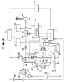
- Figure 1 is a block diagram illustrating the components of a general and basic apparatus for conducting and controlling chemical reactions pursuant to the principles and concepts of the present invention; and
- Figure 2 is a block diagram illustrating additional components for the apparatus of Figure 1.
- Apparatus which embodies the concepts and principles of the invention is illustrated in the drawings. The apparatus includes a reaction vessel (1) for containing reaction liquids and having on its outer circumference a cooling element in the form of a refrigerating jacket (71) into which refrigerant may be supplied. As shown in Figures 1 and 2, the vessel (1) has four cylindrical mouths or openings, (11), (12), (13) and (14).
- A pipe (21) communicating with a liquid container (2) containing a catalytic liquid to be added to the liquids in the vessel (1), a pipe (31) communicating with an acidic liquid container (3) containing an acidic liquid to be added to the reaction liquids, and a pipe (41) communicating with a liquid container (4) containing a basic liquid to be added to the reaction liquids, are all arranged so as to project into the vessel (1) through the opening (11). A ceramic pump (P₁) driven by a pulse motor (M₁) is arranged to move liquid along pipe (21) and into the vessel (1), a ceramic pump (P₂) driven by a pulse motor (M₂) is arranged to move liquid along the pipe (31) and into the vessel (1), and a ceramic pump (P₃) driven by a pulse motor (M₃) is arranged to move liquid along the pipe (41) and into the vessel (1). By rotational control of the motors (M₁), (M₂) and (M₃), the required amount of each respective liquid may be supplied to the vessel (1).
- The regulation of the flow volume for the additive liquid (catalytic liquid in this case) through the pipe (21) may be conducted as follows. When the pulse motor (M₁) is driven, the ceramic pump (P₁) starts to move the additive liquid contained in the additive liquid container (2) into the reaction vessel (1), and at that time, the decreasing weight of the liquid in the additive liquid container (2) is constantly detected and monitored by timely measurement with a first electronic scale (22). The scale (22) provides a signal corresponding to the present time detected weight value of liquid in the container (2) and such signal is transferred to a Central Processing Unit (CPU) (5). The CPU (5) compares the signal value outputted by the first electronic scale (22) with a preset standard value and produces a revised signal calling for adjustment of the difference between the two values to zero. The revised signal is transferred into a first speed adjustor (51) having a digital-analog converter circuit and a noise killer circuit, and the revised signal, which has been in the form of a digital signal, is converted by the adjustor (51) into a pulse signal. The pulse signal from the adjustor (51) is inputted into the pulse motor (M₁) has instructions to rotate a sufficient number of times to cause the current weight value of the container (2) to become equal to the standard value. In this embodiment, a 16-bit personal computer, No. PC-9801, made by Nihon Electric Company, may be used as the CPU (5).
- The flow of the pH adjustment liquids (acidic liquid and basic liquid) through the pipes (31) (41) is controlled and regulated as follows. A pH-sensor (61) having a glass electrode is inserted into the reaction liquids undergoing reaction in the vessel (1) through the opening (14). The sensor (61) measures the electric potential value in proportion to hydrogen ion concentration in the reaction liquids and outputs a present time pH-value signal to be transferred to the CPU (5).
- If the present time pH level signal is larger than a preset standard value for the idealistic reaction (a standard value of
pH 5 for example), the CPU (5) transfers an acid reaction supply signal to a second speed adjustor (52) so that the difference between the values may be eliminated correctly. The second speed adjustor (52), which obtains the acid reaction supply signal from the CPU (5) converts the digital signal into a pulse signal and inputs the pulse signal in the pulse motor (M₂), which drives the ceramic pump (P₂) for the required number of rotations. Thus, an appropriate quantity of acidic liquid is drawn up from the acidic liquid container (3) and moved into the reaction vessel (1) through the pipe (31), resulting in the achievement of the standard pH level in the reaction liquids. - On the other hand, if the present time pH level signal is smaller than the preset standard value, the CPU (5) transfers a basic reaction supply signal to a third speed adjustor (53) so that the difference between the values may be eliminated. The third speed adjustor (53), using a procedure which is the same as the procedure explained above, changes the digital signal into a pulse signal which is inputted into the pulse motor (M₃) driving the ceramic pump (P₃), whereby basic liquid is drawn up from the basic liquid container (4) and is moved into the reaction vessel (1) via the pipe (41).
- The flow volume of the acidic liquid and basic liquid is regulated using second and third electronic scales (32), (42) respectively for proper control, and the weight measurements and signal generations are performed in exactly the same way as in the procedures explained above for the regulation of the flow of the catalytic additive liquid.
- Reactive heat generated in the reaction vessel (1) is regulated as follows. The refrigerating jacket (71) is arranged to cover the outer circumference of the reaction vessel (1) and operates to freeze the liquid chemical system contained in the vessel (1) by use of a cooler (7). The cooler (7) may optionally be operated to cool the system to a required operating temperature. A heating tub (81) containing a heating substance is arranged beneath the reaction vessel (1), and by operation of a heater (8), the chemical reaction system contained in the reaction vessel (1) may be heated to a required reaction temperature on demand. The heating tub (81) may be moved up and down with an elevating mechanism in accordance with the arrow signs in Figure 2, although the details of such mechanism are known and are not shown in this specification.
- The cooling mechanism, which includes the jacket (71) and the cooler (7), and the heating mechanism, which includes the tub (81) and the heater (8), operate in accordance with temperature stages detected by a temperature sensor (TS) as follows:
- 1. As long as the temperature of the reaction liquids in the vessel (1) remains within a predetermined safety range, neither the cooling mechanism nor the heating mechanism is called upon to do any work. The safety range as mentioned here includes the temperature zone where the chemical reactions proceed normally and uniformly and in a stable fashion. This zone is prearranged based on values determined empirically.
- 2. Whenever the temperature of the reaction liquids in the vessel (1) rises above the safety zone yet sill below the dangerous area, the cooling mechanism (7) (71) is operated to lower the temperature back into the safety zone. The dangerous area mentioned here is the temperature area where chemical liquid reaction systems experience extreme reactions such as sudden ebullition, firing and/or explosion. This dangerous area is again predetermined based on values determined empirically to thus prevent unexpected accidents.
- 3. When the temperature of the reaction liquids in the vessel (1) is below the safety range, the heating tub (81) may be raised so as to bring the heating substance into contact with the reaction vessel (1), and the heater (8) is switched on to heat the container up to the desired reaction temperature.
- In order to obtain and maintain the necessary reaction conditions for the reaction liquids contained in the reaction vessel (1), extra gas (for instance, oxygen chlorine and carbonic acid gas) which may interfere with the progress of the chemical reaction, must be removed from the proximity of the liquid system, and such removal may be accomplished using the regulating mechanisms illustrated in Figure 2.
- With reference to Figure 2, a vacuum pump (54) is operated so that gases present in the vessel (1) may be evacuated through a degassing pipe (VP) communicating through the cylindrical opening (13). In this situation, the CPU (5) issues a signal consisting of degassing instructions, and when the signal is inputted into a driver (55), the latter converts the degassing signal into a pulse signal. The thus generated pulse signal is supplied to a pulse motor (PM) to initiate the rotation thereof at the required angular velocity. As the pulse motor (PM) rotates, a flow regulating valve (56) arranged in the degassing pipe (55) opens to facilitate evacuation of the reaction vessel (1) at the instructed flow rate. When the interior of the reaction vessel (1) becomes evacuated to the required degree, a vacuum sensor (57) detects the pressure situation and issues a signal to deenergize the pulse motor (PM) and close a vacuum cock (58). The CPU (5) then issues a signal consisting of freezing instructions to cause operation of the cooler (7) for cooling the refrigerating jacket (71), to cause the chemical liquid in the vessel (1) to become frozen. When freezing occurs, the temperature sensor (TS) installed in the reaction vessel (1) detects the situation and issues a freezing signal. When the vacuum signal issued by the vacuum sensor (57) and the freezing signal issued by the temperature sensor (TS) are both inputted together, the CPU (5) operates to open a flow regulating valve (59) in an inert gas pipe (NP) to introduce inert gas (nitorogen, for example) at the required flow rate via a driver (D) into the reaction vessel (1).
- When the vessel (1) is filled with inert gas, the CPU (5), in correspondence with the vacuum sensor (57), operates the heater (8) to elevate the temperature in the heating tub (81) so that it is able to thaw the chemical liquid system in the reaction vessel (1). The CPU (5) also operates to open the vacuum cock (58) for repeated degassing by the vacuum pump (54) under the regulation of the flow regulating valve (56).
- As explained above, the linked steps of evacuation and refilling with inert gas, freezing of the chemical reaction system liquid, thawing of the liquid, and repeated degassing, all of which contribute to the desired removal of residual gases from the chemical liquid system, reduce obstacles which otherwise would interfere with the progress of the desired reaction. All of these operations may be automatically performed using the reaction apparatus of the invention.
- The apparatus of the invention may be used to conduct surveillance of the liquid system in the vessel (1) as follows. As shown in Figures 1 and 2, an upper limit level sensor (91) and a lower limit level sensor (92) may be inserted into the reaction vessel (1) through the cylindrical opening (14). Thus, when the liquid level rises to contact the upper level sensor (91) as a result of the occurrence of bubbles caused by the influence of reactive heat, the sensor (91) is actuated to issue a signal to the level detector (9), and the level detector (9) in turn produces an electric upper limit signal which is transferred to the CPU (5). The CPU (5) then opens a ventilation valve (not shown in the drawings) to restore the pressure in the reaction vessel (1) to normal atmospheric pressure, whereupon overflow of chemical liquid is avoided.
- On the other hand, when the liquid level in the vessel (1) drops to the level of the lower limit sensor (92), the latter signals this fact to the level detector (9), and the level detector (9) produces an electric lower limit signal which is transferred to the CPU (5). The CPU (5) then generates and transfers a signal to the first speed adjustor (51) to operate the ceramic pump (P₁), whereon catalytic liquid is withdrawn from the container (2) and is supplied to the reaction vessel (1).
- The preferred embodiments of this invention have been explained above; however, the invention is not limited to these embodiments alone. Various amendments or changes are available based on the scope as described in this specification or in the claims appended hereto. For instance, a mechanism may be provided for stirring the reaction liquids in the reaction container (1). Such mechanisms may take the form of a stirring propeller (N) driven by the DC motor (M₅). The DC motor (M₅) may be operated at a constant rotational speed under the influence of a servomechanism (5b) operating via a digital-analog converter (5a). The rotational torque of the DC motor (M₅) for constant speed may be calculated by a torque calculator (5c) and transferred to the CPU (5). The rotational speed may be calculated by a rotation calculator (5d) as an analog signal which is also communicated to the CPU (5) after it is converted into a digital signal via an analog-digital converter (5e). Thus, the CPU(5) controls the servomechanism (5b) via the digital-analog converter (5a) so as to operate the DC motor (M₅) properly whenever the rotational torque or rotational speed need to be changed to accommodate changes in the viscosity of the reaction liquids in the reaction vessel (1).
- As explained in the actual embodiments set forth above, the apparatus provided by this invention accomplishes (1) the automatic and economical management of the proper supply of additive liquids like catalytic liquids or solvents and for pH-control to the liquid reaction system; (2) the removal of excess gases from the proximity of chemical liquids to be reacted; and (3) the stabilization of procedures for chemical reactions through proper restraint of excessive reactions in the reaction liquids. Therefore, the apparatus of the invention is useful for present requirements where a number of chemical experiments should be managed properly and concurrently, and is also useful to rationalise and economise chemical experimentation where in the past a large number of people were needed for managing and watching a variety of experiments.
Claims (2)
- Apparatus for conducting and controlling a chemical reaction comprising:
a reaction vessel (1) for receiving and mixing a plurality of liquids for reaction;
a plurality of containers (2, 3 and 4) for holding a supply of additive liquids to said vessel (1);
a like number of pumps (P₁, P₂ and P₃) for transporting said liquid additives from respective containers to said vessel;
a like number of motors (M₁ M₂ and M₃) for driving said pumps under the control of respective speed adjusters (51, 52 and 53);
a plurality of weighing scales (22, 32 and 42) for monitoring the weight of the respective additives in the containers (2, 3 and 4);
a temperature sensor (TS) for outputting a signal corresponding to the temperature of the reaction liquids in said vessel;
liquid level sensors (91, 92) in said vessel for outputting signals corresponding to the liquid level in said vessel;
a cooling jacket (71) surrounding the outer surface of said vessel for cooling the vessel forcibly from outside by receiving cooling fluid from a cooler (7);
a heating tub (81) containing heating fluid preheated to a required temperature, said tub being moveable by an elevator into and out of a heating relationship with the bottom of said vessel, for heating the vessel forcibly when the bottom of the vessel is submerged in the heating fluid and permitting radiation of heat from the vessel when the bottom of the vessel is separated from the heating fluid; and
a CPU (5) connected to receive signals from said temperature sensors, said liquid level sensors, and said weigh scales for monitoring and controlling the reaction
characterised in that said CPU (5) is arranged to operate;(a) when the value of the temperature signal is below a safety range, to elevate the heating tub to immerse the bottom of the vessel in the heating fluid so that a required contact area is heated;(b) when the value of the temperature signal enters the safety range from below, to lower the heating tub (81) to separate the bottom of the vessel from the heating fluid;(c) when the value of the temperature signal rises above the safety range, to supply cooling liquid to said cooling jacket;(d) when the values of the signals from said weighing scales (22, 32, 42) representing the current weight deviate from required values, to output signals corresponding to the deviation to the speed adjusters (51, 52 and 53) to keep the weight of the containers within a given proximity to the required values at a given time; and(e) when the liquid level sensor (91) produces an upper limit signal, to open a ventilation valve (not shown). - Apparatus as claimed in Claim 1 in which one of said containers (3) is for an acidic liquid and another (4) is for a basic liquid and in which there is provided a pH detector including a sensor in the reaction liquids and generating an electrical signal corresponding to the current pH level of the liquids, said CPU (5) receiving said pH signal and utilizing it in the control of its outputs to the speed adjusters (52, 53) associated with the containers (3, 4) to maintain the pH value at a desired level.
Applications Claiming Priority (2)
| Application Number | Priority Date | Filing Date | Title |
|---|---|---|---|
| JP1222160A JPH0386251A (en) | 1989-08-28 | 1989-08-28 | Chemical reaction controller |
| JP222160/89 | 1989-08-28 |
Publications (2)
| Publication Number | Publication Date |
|---|---|
| EP0415618A1 EP0415618A1 (en) | 1991-03-06 |
| EP0415618B1 true EP0415618B1 (en) | 1994-10-12 |
Family
ID=16778119
Family Applications (1)
| Application Number | Title | Priority Date | Filing Date |
|---|---|---|---|
| EP90309084A Expired - Lifetime EP0415618B1 (en) | 1989-08-28 | 1990-08-20 | Apparatus for conducting and controlling chemical reactions |
Country Status (5)
| Country | Link |
|---|---|
| US (1) | US5380485A (en) |
| EP (1) | EP0415618B1 (en) |
| JP (1) | JPH0386251A (en) |
| KR (1) | KR960001415B1 (en) |
| DE (1) | DE69013282T2 (en) |
Families Citing this family (42)
| Publication number | Priority date | Publication date | Assignee | Title |
|---|---|---|---|---|
| DE4430414A1 (en) * | 1994-08-26 | 1996-02-29 | Buna Gmbh | Chemical plant prod. correctly dispensed chemical prods. with integrated personnel and equipment protection |
| JP3560652B2 (en) * | 1994-09-06 | 2004-09-02 | コニカミノルタホールディングス株式会社 | Mixing method |
| JP2639633B2 (en) * | 1994-11-02 | 1997-08-13 | 轟産業株式会社 | Reaction heat control mechanism of heat exchange area control type in chemical reactor |
| WO1996035983A1 (en) * | 1995-05-10 | 1996-11-14 | Ferro Corporation | Control system for processes using supercritical fluids |
| US5788925A (en) * | 1996-02-16 | 1998-08-04 | Steris Corporation | Method for real time monitoring and control of load sterilization and parametric release |
| US6156267A (en) * | 1996-02-16 | 2000-12-05 | Steris Corporation | Apparatus and method for real-time monitoring and control of anti-microbial processing |
| US5816701A (en) * | 1996-04-22 | 1998-10-06 | Source For Automation, Inc. | Automated tablet dissolution apparatus |
| US5856194A (en) | 1996-09-19 | 1999-01-05 | Abbott Laboratories | Method for determination of item of interest in a sample |
| US5795784A (en) | 1996-09-19 | 1998-08-18 | Abbott Laboratories | Method of performing a process for determining an item of interest in a sample |
| US5810943A (en) * | 1996-11-27 | 1998-09-22 | Caron; Daniel | Washer apparatus with waste water pH neutralization system and method for the pH neutralization of waste water |
| US6054103A (en) * | 1997-06-25 | 2000-04-25 | Ferro Corporation | Mixing system for processes using supercritical fluids |
| US5993747A (en) * | 1997-06-25 | 1999-11-30 | Ferro Corporation | Mixing system for processes using supercritical fluids |
| US6455316B1 (en) | 1998-08-13 | 2002-09-24 | Symyx Technologies, Inc. | Parallel reactor with internal sensing and method of using same |
| US6528026B2 (en) * | 1998-08-13 | 2003-03-04 | Symyx Technologies, Inc. | Multi-temperature modular reactor and method of using same |
| US6548026B1 (en) * | 1998-08-13 | 2003-04-15 | Symyx Technologies, Inc. | Parallel reactor with internal sensing and method of using same |
| US6306658B1 (en) | 1998-08-13 | 2001-10-23 | Symyx Technologies | Parallel reactor with internal sensing |
| US6787112B1 (en) * | 1998-08-13 | 2004-09-07 | Symyx Technologies, Inc. | Parallel reactor with internal sensing and method of using same |
| US6284196B1 (en) * | 1999-04-01 | 2001-09-04 | Bp Corporation North America Inc. | Apparatus for monitor and control of an ammoxidation reactor with a fourier transform infrared spectrometer |
| US6994827B2 (en) * | 2000-06-03 | 2006-02-07 | Symyx Technologies, Inc. | Parallel semicontinuous or continuous reactors |
| US6336739B1 (en) * | 2001-03-02 | 2002-01-08 | Luke Lee | Air bath dissolution tester |
| US6692708B2 (en) * | 2001-04-05 | 2004-02-17 | Symyx Technologies, Inc. | Parallel reactor for sampling and conducting in situ flow-through reactions and a method of using same |
| US6582116B2 (en) * | 2001-09-24 | 2003-06-24 | Symyx Technologies, Inc. | Apparatus and method for mixing small volumes of reaction materials |
| US20070050092A1 (en) * | 2005-08-12 | 2007-03-01 | Symyx Technologies, Inc. | Event-based library process design |
| JP5040213B2 (en) * | 2006-08-15 | 2012-10-03 | 東京エレクトロン株式会社 | Heat treatment apparatus, heat treatment method and storage medium |
| JP2008284168A (en) * | 2007-05-17 | 2008-11-27 | Toshiba Tec Corp | Display shelf |
| US8827542B2 (en) * | 2008-07-28 | 2014-09-09 | Ganado Technologies Corp. | Apparatus and method to feed livestock |
| US8746959B2 (en) | 2007-07-26 | 2014-06-10 | Ganado Technologies Corp. | Apparatus and method to feed livestock |
| US20110229536A1 (en) * | 2008-05-12 | 2011-09-22 | Tagra Biotechnologies Ltd. | Compositions for topical application comprising microencapsulated colorants |
| MY145258A (en) * | 2009-07-06 | 2012-01-11 | Univ Sains Malaysia | A system for producing l-homophenylalanine and a process for producing l-homophenylalanine |
| GB2474249B (en) * | 2009-10-07 | 2015-11-04 | Mark Collins | An apparatus for generating heat |
| WO2013140560A1 (en) * | 2012-03-22 | 2013-09-26 | システム・インスツルメンツ株式会社 | AUTOMATIC pH ADJUSTMENT APPARATUS |
| CN104246514B (en) * | 2012-04-24 | 2016-08-17 | 小滴喷射有限公司 | Spraying system and method of spraying using the spraying system |
| WO2015132791A1 (en) | 2014-03-04 | 2015-09-11 | Tagra Biotechnologies Ltd. | Colorant-containing microcapsules |
| WO2015132792A1 (en) | 2014-03-04 | 2015-09-11 | Tagra Biotechnologies Ltd. | Active agent-containing microcapsules |
| WO2017037716A2 (en) | 2015-09-03 | 2017-03-09 | Tagra Biotechnologies Ltd. | Microcapsules encapsulating a reflective agent |
| CN106732291A (en) * | 2017-02-07 | 2017-05-31 | 李瑾然 | A kind of chemical reaction equipment |
| JP7015638B2 (en) * | 2017-02-23 | 2022-02-03 | 株式会社ディスコ | Machining liquid supply device |
| GB201719769D0 (en) | 2017-11-28 | 2018-01-10 | Cronin 3D Ltd | Analytical device and methods of use |
| CN108682266A (en) * | 2018-06-21 | 2018-10-19 | 山东东泰水处理有限公司 | A kind of reverse osmosis antisludging agent work demo rack |
| EP3617304A1 (en) * | 2018-08-31 | 2020-03-04 | C-CIT Sensors AG | System for the controlled execution of a biotransformation process |
| CN114234679A (en) * | 2022-01-06 | 2022-03-25 | 浙江亚微精密机床有限公司 | Heat exchanger capable of adjusting heat exchange area according to temperature change |
| US11998884B1 (en) | 2023-03-02 | 2024-06-04 | Erlan H. Feria | Method for controlling lingerature of chemical reaction |
Family Cites Families (14)
| Publication number | Priority date | Publication date | Assignee | Title |
|---|---|---|---|---|
| US2984386A (en) * | 1957-09-10 | 1961-05-16 | White Roby Byron | Intermittent time-rate controller |
| FR2140832A5 (en) * | 1971-06-09 | 1973-01-19 | Combinatul Chimic Fagara | Ammonium nitrate prodn - with automatic control of neutralisation |
| US3749285A (en) * | 1971-09-13 | 1973-07-31 | Haemonetics Corp | Programmed liquid delivery system |
| US3926738A (en) * | 1972-05-10 | 1975-12-16 | Wilson John D | Method and apparatus for control of biochemical processes |
| SE387657B (en) * | 1973-07-09 | 1976-09-13 | Alfa Laval Ab | CONTINUES WITH CONTINUOUS JESNING, WHICH AFTER THE JESNING SEPARATION TAKES PLACE BY CENTRIFUGATION IN THREE COMPONENTS, Namely CULTIVATION LIQUID, LIVING CELL MASS AND POLLUTIONS |
| DE2543307C3 (en) * | 1975-09-27 | 1981-06-19 | Standard-Messo Duisburg, Gesellschaft für Chemietechnik mbH & Co, 4100 Duisburg | Method and device for fermenting carbohydrate-containing nutrient substrate |
| US4212950A (en) * | 1978-05-08 | 1980-07-15 | The Virtis Company, Inc. | Fermenting apparatus |
| US4264741A (en) * | 1979-06-05 | 1981-04-28 | New Brunswick Scientific Co., Inc. | Tiltable fermentor |
| US4411649A (en) * | 1979-07-12 | 1983-10-25 | Baxter Travenol Laboratories, Inc. | Fluid flow control system |
| US4590158A (en) * | 1979-10-01 | 1986-05-20 | Eikman Edward A | Microbial monitor |
| US4371623A (en) * | 1981-02-09 | 1983-02-01 | William N. Durkin | Solar still |
| US4702888A (en) * | 1983-06-30 | 1987-10-27 | Electric Power Research Institute, Inc. | Stirred microreactor |
| DE3634203A1 (en) * | 1986-10-08 | 1988-04-21 | Boehringer Mannheim Gmbh | BIOREACTOR FOR CULTIVATING BIOLOGICAL MATERIAL |
| US4844298A (en) * | 1987-03-11 | 1989-07-04 | Sumitomo Electric Industries, Ltd. | Apparatus for automatically dispensing accurately a predetermined quantity of liquids required to be stored at constant temperatures |
-
1989
- 1989-08-28 JP JP1222160A patent/JPH0386251A/en active Granted
-
1990
- 1990-08-20 DE DE69013282T patent/DE69013282T2/en not_active Expired - Fee Related
- 1990-08-20 EP EP90309084A patent/EP0415618B1/en not_active Expired - Lifetime
- 1990-08-23 KR KR1019900013048A patent/KR960001415B1/en not_active Expired - Lifetime
-
1992
- 1992-09-18 US US07/946,779 patent/US5380485A/en not_active Expired - Lifetime
Also Published As
| Publication number | Publication date |
|---|---|
| HK1000461A1 (en) | 1998-03-27 |
| EP0415618A1 (en) | 1991-03-06 |
| KR960001415B1 (en) | 1996-01-27 |
| US5380485A (en) | 1995-01-10 |
| JPH0474054B2 (en) | 1992-11-25 |
| DE69013282D1 (en) | 1994-11-17 |
| JPH0386251A (en) | 1991-04-11 |
| DE69013282T2 (en) | 1995-03-09 |
| KR910004245A (en) | 1991-03-28 |
Similar Documents
| Publication | Publication Date | Title |
|---|---|---|
| US5380485A (en) | Apparatus for conducting and controlling chemical reactions | |
| KR100238633B1 (en) | Reaction Heat Control Mechanism of Heat Exchange Area Control in Chemical Reactor | |
| Skelland et al. | Drop size and continuous‐phase mass transfer in agitated vessels | |
| US5098667A (en) | Particulate flow control | |
| EP0677315A2 (en) | Automatic feedback control system and method for a water treatment apparatus | |
| JPS61202684A (en) | Method and apparatus for controlling dissolved oxygen and phof medium | |
| SE436698B (en) | CHEMICAL REACTION DEVICE | |
| Mills et al. | Effect of solids on oxygen transfer in agitated three‐phase systems | |
| CN113198202A (en) | Automatic control platform and method for high-throughput parallel crystallization screening | |
| CA1315567C (en) | Automated calorimeter and methods of operating the same | |
| Kaufmann et al. | Mechanism of interfacial mass transfer in membrane transport | |
| US3676653A (en) | Measurement of heat generated in exothermic reaction | |
| HK1000461B (en) | Apparatus for conducting and controlling chemical reactions | |
| US3653835A (en) | Specific gravity analyzer for control of an alkylation process | |
| US3645697A (en) | Controlling apparatus of a reactor | |
| US3513220A (en) | Specific gravity analyzer for control of an alkylation process | |
| CN209155836U (en) | A kind of novel tank reactor | |
| CN110926903A (en) | Co-precipitation device | |
| JPH11255809A (en) | Concentration control method of polymerization initiator and concentration control device | |
| CN121554078B (en) | Intelligent multi-mode fusion water treatment closed-loop control system and method | |
| US4469560A (en) | Control of dumping of a reactor | |
| Stockton et al. | Versatile macroscale heat flow calorimeter for the study of chemical processes | |
| CN214439064U (en) | System for determining reaction conditions for preparing isocyanate by phosgene liquid phase method | |
| Fischer | GLOVEBOX FACILITY FOR PYROCHEMICAL RESEARCH AND DEVELOPMENT WORK WITH $ sup 238$ Pu. | |
| CN118422287A (en) | Array reaction equipment for metal processing technology |
Legal Events
| Date | Code | Title | Description |
|---|---|---|---|
| PUAI | Public reference made under article 153(3) epc to a published international application that has entered the european phase |
Free format text: ORIGINAL CODE: 0009012 |
|
| AK | Designated contracting states |
Kind code of ref document: A1 Designated state(s): CH DE FR GB IT LI |
|
| 17P | Request for examination filed |
Effective date: 19910904 |
|
| 17Q | First examination report despatched |
Effective date: 19920218 |
|
| GRAA | (expected) grant |
Free format text: ORIGINAL CODE: 0009210 |
|
| AK | Designated contracting states |
Kind code of ref document: B1 Designated state(s): CH DE FR GB IT LI |
|
| ITF | It: translation for a ep patent filed | ||
| REF | Corresponds to: |
Ref document number: 69013282 Country of ref document: DE Date of ref document: 19941117 |
|
| ET | Fr: translation filed | ||
| PLBE | No opposition filed within time limit |
Free format text: ORIGINAL CODE: 0009261 |
|
| STAA | Information on the status of an ep patent application or granted ep patent |
Free format text: STATUS: NO OPPOSITION FILED WITHIN TIME LIMIT |
|
| 26N | No opposition filed | ||
| REG | Reference to a national code |
Ref country code: GB Ref legal event code: IF02 |
|
| REG | Reference to a national code |
Ref country code: CH Ref legal event code: PFA Owner name: TODOROKI SANGYO KABUSHIKI KAISHA Free format text: TODOROKI SANGYO KABUSHIKI KAISHA#NO. 3-2-4, KEYA#FUKUI-SHI/FUKI-KEN (JP) -TRANSFER TO- TODOROKI SANGYO KABUSHIKI KAISHA#NO. 3-2-4, KEYA#FUKUI-SHI/FUKI-KEN (JP) |
|
| PGFP | Annual fee paid to national office [announced via postgrant information from national office to epo] |
Ref country code: DE Payment date: 20080905 Year of fee payment: 19 Ref country code: CH Payment date: 20080918 Year of fee payment: 19 |
|
| PGFP | Annual fee paid to national office [announced via postgrant information from national office to epo] |
Ref country code: FR Payment date: 20080818 Year of fee payment: 19 Ref country code: IT Payment date: 20080827 Year of fee payment: 19 |
|
| PGFP | Annual fee paid to national office [announced via postgrant information from national office to epo] |
Ref country code: GB Payment date: 20080827 Year of fee payment: 19 |
|
| REG | Reference to a national code |
Ref country code: CH Ref legal event code: PL |
|
| GBPC | Gb: european patent ceased through non-payment of renewal fee |
Effective date: 20090820 |
|
| PG25 | Lapsed in a contracting state [announced via postgrant information from national office to epo] |
Ref country code: LI Free format text: LAPSE BECAUSE OF NON-PAYMENT OF DUE FEES Effective date: 20090831 Ref country code: CH Free format text: LAPSE BECAUSE OF NON-PAYMENT OF DUE FEES Effective date: 20090831 |
|
| REG | Reference to a national code |
Ref country code: FR Ref legal event code: ST Effective date: 20100430 |
|
| PG25 | Lapsed in a contracting state [announced via postgrant information from national office to epo] |
Ref country code: DE Free format text: LAPSE BECAUSE OF NON-PAYMENT OF DUE FEES Effective date: 20100302 Ref country code: FR Free format text: LAPSE BECAUSE OF NON-PAYMENT OF DUE FEES Effective date: 20090831 |
|
| PG25 | Lapsed in a contracting state [announced via postgrant information from national office to epo] |
Ref country code: GB Free format text: LAPSE BECAUSE OF NON-PAYMENT OF DUE FEES Effective date: 20090820 |
|
| PG25 | Lapsed in a contracting state [announced via postgrant information from national office to epo] |
Ref country code: IT Free format text: LAPSE BECAUSE OF NON-PAYMENT OF DUE FEES Effective date: 20090820 |