EP0414237A2 - An image processing equipment - Google Patents
An image processing equipment Download PDFInfo
- Publication number
- EP0414237A2 EP0414237A2 EP90116120A EP90116120A EP0414237A2 EP 0414237 A2 EP0414237 A2 EP 0414237A2 EP 90116120 A EP90116120 A EP 90116120A EP 90116120 A EP90116120 A EP 90116120A EP 0414237 A2 EP0414237 A2 EP 0414237A2
- Authority
- EP
- European Patent Office
- Prior art keywords
- pulse
- light
- time
- stimulus
- image
- Prior art date
- Legal status (The legal status is an assumption and is not a legal conclusion. Google has not performed a legal analysis and makes no representation as to the accuracy of the status listed.)
- Granted
Links
Images


Classifications
-
- G—PHYSICS
- G01—MEASURING; TESTING
- G01N—INVESTIGATING OR ANALYSING MATERIALS BY DETERMINING THEIR CHEMICAL OR PHYSICAL PROPERTIES
- G01N21/00—Investigating or analysing materials by the use of optical means, i.e. using sub-millimetre waves, infrared, visible or ultraviolet light
- G01N21/62—Systems in which the material investigated is excited whereby it emits light or causes a change in wavelength of the incident light
- G01N21/63—Systems in which the material investigated is excited whereby it emits light or causes a change in wavelength of the incident light optically excited
- G01N21/64—Fluorescence; Phosphorescence
- G01N21/645—Specially adapted constructive features of fluorimeters
- G01N21/6456—Spatial resolved fluorescence measurements; Imaging
- G01N21/6458—Fluorescence microscopy
Definitions
- the present invention relates to an image processing equipment, wherein a sample such as a sample of cardiomyocytes is subjected to a stimulus so that the change in fluorescence with time can be measured at a high time resolution.
- a sample is subjected to an uninterrupted light emitted by a continuously lit light source lamp; the time resolution for obtaining data cannot be made higher than 1/30 sec.,which is the time required for 1 frame, and thus no higher time resolution is available.
- No data representing the change with the time corresponding to the duration of the stimulus can be obtained, since the device for giving the stimulus to the sample cannot be synchronized with the television camera.
- the change in Ca2+ concentration resulting from the contraction of the cardiomyocyte can be measured by the intensity of the fluorescence of the reagent loaded in the cells.
- the process (of the change in the Ca2+ concentration) cannot be observed in detail by the conventional method using the television camera, since the change of contraction of the heart occurs at a rate in the order of milli-seconds.
- the object of the present invention is to provide an equipment capable of two-dimensionally analyzing the change in the fluorescence at a time resolution in the order of a milli-second or less.
- Another object of the present invention is to provide an equipment capable of two-dimensionally analyzing the change in the shape of a single cardiomyocyte due to contraction and dynamic behavior of the intracellular Ca2+; concentration over time by combining a fluorescence microscope with a television camera.
- the equipment according to the present invention for measuring the change with the time in a sample by a high-sensitivity television camera comprises a pulse-light-up light source for emitting two pulse excitation light-pulses differing in the wavelength during the blanking period of said high-sensitivity television camera, a stimulating device for giving the stimulus to the sample at the moment of time preceding to the light emission timing of the pulse-light-up light source by a certain time period and a timing signal generator to generate timing signals to determine the scan timing of the high-sensitivity television camera, the timing of the pulse excitation light-pulse from the pulse-light-up light source and the timing of the stimulating signal from the stimulating device.
- a fluorescent reagent is loaded into a sample of cardiomyocytes to cause the intracellular carboxyl groups to be bonded to the Ca2+ the external stimulus is given to the cardiomyocyte; the two pulse excitation light-pulses differing in their wavelengths are given to said cardiomyocyte; and the image of the cardiomyocyte is taken by the high-sensitivity television camera.
- the pulse light coincides with the blanking period of the television camera;
- the stimulus timing is set according to the time of the emission of said pulse excitation light-pulses;
- the television camera is adapted for taking the image of the sample by scanning for at least one frame out of the blanking period, whereas the image will not be taken while the sample is exposed to the pulse excitation light.
- This image processing equipment enables the timing of the stimulus to be varied according to various requirements in measuring, the plural number of image data to be stored in the memory, said image data to be re-synthesized for observing the change in the image and the change in the shape of a single cardiomyocyte occurring at the rate in the order of a milli-second due to the contraction of the cardiomyocyte and the concurrent dynamic change in the intracellular Ca2+ concentration to be analyzed two-dimensionally.
- Fig. 1 represents the fluorescence microscope, wherein the sample 3 such as that of cardiomyocytes with a fluorescent reagent loaded thereinto is placed on the side of an objective lens 2 of the microscope 1.
- the pulse-light-up light source 4 is provided for irradiating the sample 3 with pulse excitation light-pulses of single wavelength or of different wavelengths.
- a high-sensitivity television camera 5 is installed on the output side of the fluorescence microscope 1.
- a CPU 6 com prising an image processor is connected to the output side of the high-sensitivity television camera 5. This CPU 6 is connected to a keyboard 7 for inputting data for processing, a command for analysis and other data.
- a color monitor 8 is provided for displaying an image analysis menu and the data.
- a RAM 9 is provided for temporarily storing image data.
- a ROM 10 is provided for storing programs for the analysis, for processing, for reading and storing the data.
- An image memory 11 for storing the image data and a printer 12 are provided for printing the measured data.
- a timing signal generator 13 is provided for generating a timing signal. The timing signal generator 13 generates a drive signal for the sequential-scanning high-sensitivity television camera 5, the timing signal for writing in the image memory 11, a timing signal for a stimulus generator 15 and a pulse-light-up timing signal for a light source controller 14.
- the cardiomyocytes 3 whereinto the fluorescent reagent is injected is set on the side of the objective lens 2 of the fluorescence microscope 1.
- the measurement is started at a time t1 shown in Fig. 2.
- the equipment waits until the first vertical synchronizing signal is detected.
- the timing signal is generated by the timing signal generator 13 at a time t3 after a predetermined time (A-F) from the time t2.
- this timing signal causes the stimulus signal to be outputted from the stimulus generating device 15.
- A represents the period of one vertical synchronizing signal
- F represents the time-interval from A to the next vertical blanking period.
- the stimulus signal is outputted at the time t3.
- This causes a micro elec trode 16 to apply a stimulating current to the cardiomyocytes 3.
- the timing signal is outputted from the timing signal generator 13 at a time t4, which is in the next vertical blanking period and after the predetermined time period F from the time t3 for the output of the stimulus signal. This causes through the light source controller 14 the pulse excitation light-pulse from the pulse-light-up light source 4 to be projected on the cardiomyocytes 3.
- the pulse excitation light-pulse it is essential for the pulse excitation light-pulse to occur during the vertical blanking period D, and this enables the stimulus timing signal to be outputted before the predetermined time of output of the pulse excitation light-pulse.
- the cardiomyocyte 3 is irradiated with the excitation lights having different wavelengths, for example the pulse excitation lights (G) of 340 nm and 360 nm or 340 nm and 380 nm, coming from said pulse-light-up light source 4.
- G pulse excitation lights
- This causes the flurescent images differing in the intensity of fluorescence depending on the wavelength of the light to depending on the wavelength of the light being generated by the cardiomyocyte 3, and these fluorescent images are taken by the high-sensitivity television camera 5.
- the image signal from said television camera is stored in the image memory 11 through the CPU 6 and displayed on the television monitor 8 or printed by the printer 12.
- the image can be obtained after a certain period of time F or at the time t4. That is, the stimulus is given at the time t3 preceding to the time t4 for the light-up or light-pulse of the pulse light source, and, after a certain period of time F, the fluorescent image can be obtained during the period C between the time t5 and the time t6 by scanning with the television camera 5.
- the different images can be obtained by varying the time t3 for the timing of said stimulus.
- the plural number of image data are stored in the image memory 11, and the stored data are accessed by the CPU 6 for analysis. More particularly, the Ca2+ concentration is calculated using a calibration graph of the fluorescence ratio and Ca2+ (concentration). To obtain this calibration graph, known Ca2+ concentrations of some samples are stored in the ROM 10 in advance, and the intensity of fluorescence of the sample is measured by CPU 6 after processing the sample with the fluorescent reagent and two different pulse excitation light-pulses.
- the pulse excitation light is generated during the vertical blanking period D of the frame of 1/30 sec., but, where a faster analysis is required, the pulse excitation light-pulse may be generated during the horizontal blanking period.
Landscapes
- Health & Medical Sciences (AREA)
- Nuclear Medicine, Radiotherapy & Molecular Imaging (AREA)
- Physics & Mathematics (AREA)
- Life Sciences & Earth Sciences (AREA)
- Chemical & Material Sciences (AREA)
- Analytical Chemistry (AREA)
- Biochemistry (AREA)
- General Health & Medical Sciences (AREA)
- General Physics & Mathematics (AREA)
- Immunology (AREA)
- Pathology (AREA)
- Investigating, Analyzing Materials By Fluorescence Or Luminescence (AREA)
- Measuring And Recording Apparatus For Diagnosis (AREA)
- Image Processing (AREA)
- Image Analysis (AREA)
- Medical Treatment And Welfare Office Work (AREA)
- Investigating Or Analysing Biological Materials (AREA)
- Electrical Discharge Machining, Electrochemical Machining, And Combined Machining (AREA)
- Ultra Sonic Daignosis Equipment (AREA)
- Polarising Elements (AREA)
Abstract
Description
- The present invention relates to an image processing equipment, wherein a sample such as a sample of cardiomyocytes is subjected to a stimulus so that the change in fluorescence with time can be measured at a high time resolution.
- In a conventional image pick up method using a television camera, a sample is subjected to an uninterrupted light emitted by a continuously lit light source lamp; the time resolution for obtaining data cannot be made higher than 1/30 sec.,which is the time required for 1 frame, and thus no higher time resolution is available. No data representing the change with the time corresponding to the duration of the stimulus can be obtained, since the device for giving the stimulus to the sample cannot be synchronized with the television camera. For example the change in Ca²⁺ concentration resulting from the contraction of the cardiomyocyte can be measured by the intensity of the fluorescence of the reagent loaded in the cells. However, the process (of the change in the Ca²⁺ concentration) cannot be observed in detail by the conventional method using the television camera, since the change of contraction of the heart occurs at a rate in the order of milli-seconds.
- There is another method using a photomultiplier tube instead of the television camera, wherein the fluorescence at a point within the visual field of the microscope or the fluorescence of many samples put in a cuvette is measured. This method using a photomultiplier enables us to measure the intensity of the fluorescence at a high time resolution, but no two-dimensional analysis of the fluorescence of the sample is possible due to the spot detection.
- The object of the present invention is to provide an equipment capable of two-dimensionally analyzing the change in the fluorescence at a time resolution in the order of a milli-second or less.
- Another object of the present invention is to provide an equipment capable of two-dimensionally analyzing the change in the shape of a single cardiomyocyte due to contraction and dynamic behavior of the intracellular Ca²⁺; concentration over time by combining a fluorescence microscope with a television camera.
- The objects and other characteristics of the present invention will be described hereunder.
- The equipment according to the present invention for measuring the change with the time in a sample by a high-sensitivity television camera comprises a pulse-light-up light source for emitting two pulse excitation light-pulses differing in the wavelength during the blanking period of said high-sensitivity television camera, a stimulating device for giving the stimulus to the sample at the moment of time preceding to the light emission timing of the pulse-light-up light source by a certain time period and a timing signal generator to generate timing signals to determine the scan timing of the high-sensitivity television camera, the timing of the pulse excitation light-pulse from the pulse-light-up light source and the timing of the stimulating signal from the stimulating device.
- In this image processing equipment, a fluorescent reagent is loaded into a sample of cardiomyocytes to cause the intracellular carboxyl groups to be bonded to the Ca²⁺ the external stimulus is given to the cardiomyocyte; the two pulse excitation light-pulses differing in their wavelengths are given to said cardiomyocyte; and the image of the cardiomyocyte is taken by the high-sensitivity television camera. In this system, the pulse light coincides with the blanking period of the television camera; the stimulus timing is set according to the time of the emission of said pulse excitation light-pulses; the television camera is adapted for taking the image of the sample by scanning for at least one frame out of the blanking period, whereas the image will not be taken while the sample is exposed to the pulse excitation light. This image processing equipment enables the timing of the stimulus to be varied according to various requirements in measuring, the plural number of image data to be stored in the memory, said image data to be re-synthesized for observing the change in the image and the change in the shape of a single cardiomyocyte occurring at the rate in the order of a milli-second due to the contraction of the cardiomyocyte and the concurrent dynamic change in the intracellular Ca²⁺ concentration to be analyzed two-dimensionally.
- In the following, preferred embodiments of the invention are explained in detail.
- Fig. 1 is a block diagram showing an embodiment of the present invention relating to an image processing equipment.
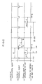
- Fig. 2 is a time chart showing the operations of the equipment according to the present invention.
- Fig. 3 is a flow chart showing the sequence of the operations of the equipment according to the present invention.
- An embodiment of the present invention will be explained hereunder in reference to the drawings.
- In Fig. 1, 1 represents the fluorescence microscope, wherein the
sample 3 such as that of cardiomyocytes with a fluorescent reagent loaded thereinto is placed on the side of anobjective lens 2 of the microscope 1. The pulse-light-uplight source 4 is provided for irradiating thesample 3 with pulse excitation light-pulses of single wavelength or of different wavelengths. A high-sensitivity television camera 5 is installed on the output side of the fluorescence microscope 1. ACPU 6 com prising an image processor is connected to the output side of the high-sensitivity television camera 5. ThisCPU 6 is connected to akeyboard 7 for inputting data for processing, a command for analysis and other data. Acolor monitor 8 is provided for displaying an image analysis menu and the data. ARAM 9 is provided for temporarily storing image data. AROM 10 is provided for storing programs for the analysis, for processing, for reading and storing the data. Animage memory 11 for storing the image data and aprinter 12 are provided for printing the measured data. Atiming signal generator 13 is provided for generating a timing signal. Thetiming signal generator 13 generates a drive signal for the sequential-scanning high-sensitivity television camera 5, the timing signal for writing in theimage memory 11, a timing signal for astimulus generator 15 and a pulse-light-up timing signal for alight source controller 14. - The operation of the image processing equipment having the above-described composition will be explained next in reference to the drawings.
- Loading the fluorescent reagent into the sample of the
cardiomyocytes 3 causes the intracellular, its carboxyl group to be bonded to the Ca²⁺ in thecardiomyocytes 3. Thecardiomyocytes 3 whereinto the fluorescent reagent is injected is set on the side of theobjective lens 2 of the fluorescence microscope 1. The measurement is started at a time t₁ shown in Fig. 2. After starting the measurement, the equipment waits until the first vertical synchronizing signal is detected. When the first vertical synchronizing signal is received at a time t₂, the timing signal is generated by thetiming signal generator 13 at a time t₃ after a predetermined time (A-F) from the time t₂. The generation of this timing signal causes the stimulus signal to be outputted from the stimulus generatingdevice 15. Here, A represents the period of one vertical synchronizing signal, while F represents the time-interval from A to the next vertical blanking period. The stimulus signal is outputted at the time t₃. This causes amicro elec trode 16 to apply a stimulating current to thecardiomyocytes 3. The timing signal is outputted from thetiming signal generator 13 at a time t₄, which is in the next vertical blanking period and after the predetermined time period F from the time t₃ for the output of the stimulus signal. This causes through thelight source controller 14 the pulse excitation light-pulse from the pulse-light-uplight source 4 to be projected on thecardiomyocytes 3. Here, it is essential for the pulse excitation light-pulse to occur during the vertical blanking period D, and this enables the stimulus timing signal to be outputted before the predetermined time of output of the pulse excitation light-pulse. In the above-described embodiment, the time t₃ for outputting the stimulus timing signal is set within one frame (c) of (before) the time t₄ for the timing of the pulse excitation light, but said output time t₃ is not limited within said one frame and thus may be set taking more than one frame, that is a plural number of frames (B = nA). - The
cardiomyocyte 3 is irradiated with the excitation lights having different wavelengths, for example the pulse excitation lights (G) of 340 nm and 360 nm or 340 nm and 380 nm, coming from said pulse-light-uplight source 4. This causes the flurescent images differing in the intensity of fluorescence depending on the wavelength of the light to depending on the wavelength of the light being generated by thecardiomyocyte 3, and these fluorescent images are taken by the high-sensitivity television camera 5. - The image signal from said television camera is stored in the
image memory 11 through theCPU 6 and displayed on thetelevision monitor 8 or printed by theprinter 12. Thus, when the stimulus is given at the time t₃, the image can be obtained after a certain period of time F or at the time t₄. That is, the stimulus is given at the time t₃ preceding to the time t₄ for the light-up or light-pulse of the pulse light source, and, after a certain period of time F, the fluorescent image can be obtained during the period C between the time t₅ and the time t₆ by scanning with thetelevision camera 5. The different images can be obtained by varying the time t₃ for the timing of said stimulus. - The plural number of image data are stored in the
image memory 11, and the stored data are accessed by theCPU 6 for analysis. More particularly, the Ca²⁺ concentration is calculated using a calibration graph of the fluorescence ratio and Ca²⁺ (concentration). To obtain this calibration graph, known Ca²⁺ concentrations of some samples are stored in theROM 10 in advance, and the intensity of fluorescence of the sample is measured byCPU 6 after processing the sample with the fluorescent reagent and two different pulse excitation light-pulses. - In the above-described embodiment, the pulse excitation light is generated during the vertical blanking period D of the frame of 1/30 sec., but, where a faster analysis is required, the pulse excitation light-pulse may be generated during the horizontal blanking period.
- From the aforegoing, it becomes clear that the present invention concerns an apparatus as well as a method for analyzing.
Claims (3)
characterized by a pulse-light-up light source (4) for emitting pulse excitation light during the blanking period of said high-sensitivity television camera (5), a stimulus generating device (15, 16) for giving a stimulus to the sample (3) at a time (t₃) preceding the time (t₄) at which light is emitted from said pulse-light-up light source (4) by the predetermined time period (F) and a timing signal generator (13) for generating timing signals for said high-sensitivity television camera (5), said pulse-light-up light source (4) and said stimulus generating device (15, 16).
characterized in that a plural number of images is obtained by varying the timing (t₃) of the stimulus according to the time (t₄) of the emission of the pulse excitation light so that the change in the condition of the image can be observed by re-synthesizing the whole image.
Applications Claiming Priority (2)
| Application Number | Priority Date | Filing Date | Title |
|---|---|---|---|
| JP21978089A JP2864130B2 (en) | 1989-08-25 | 1989-08-25 | Image processing device |
| JP219780/89 | 1989-08-25 |
Publications (3)
| Publication Number | Publication Date |
|---|---|
| EP0414237A2 true EP0414237A2 (en) | 1991-02-27 |
| EP0414237A3 EP0414237A3 (en) | 1994-01-12 |
| EP0414237B1 EP0414237B1 (en) | 1997-05-14 |
Family
ID=16740889
Family Applications (1)
| Application Number | Title | Priority Date | Filing Date |
|---|---|---|---|
| EP90116120A Expired - Lifetime EP0414237B1 (en) | 1989-08-25 | 1990-08-22 | An image processing equipment |
Country Status (5)
| Country | Link |
|---|---|
| US (1) | US5047846A (en) |
| EP (1) | EP0414237B1 (en) |
| JP (1) | JP2864130B2 (en) |
| AT (1) | ATE153156T1 (en) |
| DE (1) | DE69030697T2 (en) |
Cited By (2)
| Publication number | Priority date | Publication date | Assignee | Title |
|---|---|---|---|---|
| EP1728856A1 (en) | 2005-06-01 | 2006-12-06 | Fraunhofer-Gesellschaft zur Förderung der angewandten Forschung e.V. | A method for optically determining the dynamic behaviour of contracting muscle cells |
| US7436515B2 (en) | 2003-06-26 | 2008-10-14 | The Secretary Of State Of Defense, Dstl | Fluid borne particle analyzers |
Families Citing this family (15)
| Publication number | Priority date | Publication date | Assignee | Title |
|---|---|---|---|---|
| US5223932A (en) * | 1991-01-10 | 1993-06-29 | Wayne State University | Dynamic offset to increase the range of digitization of video images |
| KR19990087771A (en) * | 1996-03-13 | 1999-12-27 | 조지프 비. 볼프 | Real time multipath video imaging system |
| US6650357B1 (en) * | 1997-04-09 | 2003-11-18 | Richardson Technologies, Inc. | Color translating UV microscope |
| JPH11219425A (en) * | 1998-01-30 | 1999-08-10 | Lintec Corp | Observation device and light emission control method of the device |
| CN100396242C (en) * | 2003-01-20 | 2008-06-25 | 株式会社东芝 | X-ray diagnostic equipment with X-ray fluoroscopy function |
| US9186093B2 (en) * | 2008-08-20 | 2015-11-17 | The Regents Of The University Of California | Compositions and methods for screening cardioactive drugs |
| CN103620390B (en) | 2011-06-21 | 2016-08-31 | 浜松光子学株式会社 | Optical measurement device, optical measurement method, and optical measurement program |
| JP5869239B2 (en) | 2011-06-21 | 2016-02-24 | 浜松ホトニクス株式会社 | Light measurement apparatus, light measurement method, and light measurement program |
| MX346174B (en) | 2012-07-26 | 2017-03-10 | Depuy Synthes Products Inc | YCBCR PULSED LIGHTING SCHEME IN A DEFICIENT LIGHT ENVIRONMENT. |
| AU2013295553B2 (en) * | 2012-07-26 | 2017-10-19 | DePuy Synthes Products, Inc. | Continuous video in a light deficient environment |
| CA2906821A1 (en) | 2013-03-15 | 2014-09-18 | Olive Medical Corporation | Scope sensing in a light controlled environment |
| JP6404318B2 (en) | 2013-03-15 | 2018-10-10 | デピュイ・シンセス・プロダクツ・インコーポレイテッド | Integrated optical energy control of laser pulses |
| JP2016519591A (en) | 2013-03-15 | 2016-07-07 | オリーブ・メディカル・コーポレイションOlive Medical Corporation | Super-resolution and color motion artifact correction in pulse color imaging system |
| JP2015146747A (en) * | 2014-02-05 | 2015-08-20 | 浜松ホトニクス株式会社 | Cell determination method |
| AU2015230978B2 (en) | 2014-03-21 | 2020-01-23 | DePuy Synthes Products, Inc. | Card edge connector for an imaging sensor |
Family Cites Families (5)
| Publication number | Priority date | Publication date | Assignee | Title |
|---|---|---|---|---|
| JPS59151937A (en) * | 1983-02-01 | 1984-08-30 | 株式会社東芝 | Diagnostic x-ray television apparatus |
| US4877965A (en) * | 1985-07-01 | 1989-10-31 | Diatron Corporation | Fluorometer |
| US4713686A (en) * | 1985-07-02 | 1987-12-15 | Bridgestone Corporation | High speed instantaneous multi-image recorder |
| US4882498A (en) * | 1987-10-09 | 1989-11-21 | Pressco, Inc. | Pulsed-array video inspection lighting system |
| US4878116A (en) * | 1988-06-02 | 1989-10-31 | Wayne State University | Vector lock-in imaging system |
-
1989
- 1989-08-25 JP JP21978089A patent/JP2864130B2/en not_active Expired - Lifetime
-
1990
- 1990-08-20 US US07/570,249 patent/US5047846A/en not_active Expired - Fee Related
- 1990-08-22 EP EP90116120A patent/EP0414237B1/en not_active Expired - Lifetime
- 1990-08-22 AT AT90116120T patent/ATE153156T1/en not_active IP Right Cessation
- 1990-08-22 DE DE69030697T patent/DE69030697T2/en not_active Expired - Fee Related
Cited By (2)
| Publication number | Priority date | Publication date | Assignee | Title |
|---|---|---|---|---|
| US7436515B2 (en) | 2003-06-26 | 2008-10-14 | The Secretary Of State Of Defense, Dstl | Fluid borne particle analyzers |
| EP1728856A1 (en) | 2005-06-01 | 2006-12-06 | Fraunhofer-Gesellschaft zur Förderung der angewandten Forschung e.V. | A method for optically determining the dynamic behaviour of contracting muscle cells |
Also Published As
| Publication number | Publication date |
|---|---|
| DE69030697T2 (en) | 1998-01-02 |
| EP0414237B1 (en) | 1997-05-14 |
| JP2864130B2 (en) | 1999-03-03 |
| DE69030697D1 (en) | 1997-06-19 |
| JPH0383174A (en) | 1991-04-09 |
| US5047846A (en) | 1991-09-10 |
| EP0414237A3 (en) | 1994-01-12 |
| ATE153156T1 (en) | 1997-05-15 |
Similar Documents
| Publication | Publication Date | Title |
|---|---|---|
| EP0414237B1 (en) | An image processing equipment | |
| JP2527540B2 (en) | Device for fluorescence signal analysis and image display | |
| US7453567B2 (en) | Fluorescence lifetime distribution image measuring system and its measuring method | |
| EP0188758B1 (en) | A method for detecting fingerprints using a laser | |
| JPH0762868B2 (en) | Wiring pattern defect inspection method for printed circuit board | |
| US7038193B2 (en) | Method and device for separating different emission wavelengths in a scanning microscope | |
| WO1988007670A3 (en) | Time-resolved fluorescence apparatus and immunoassay | |
| KR100319675B1 (en) | System and method for detecting particles produced in a process chamber by scattering light | |
| US5071249A (en) | Light waveform measuring apparatus | |
| JP2002286639A (en) | Time-resolved fluorescence detecting device | |
| JP5052009B2 (en) | Scanning microscope and specimen image acquisition method | |
| JP4037381B2 (en) | Optical information reading method and apparatus | |
| JPH0262806B2 (en) | ||
| JPH08178829A (en) | Flow cytometer | |
| JP4045470B2 (en) | Confocal microscope | |
| JPS60242344A (en) | Measuring instrument of characteristic of luminous body | |
| JPH08178826A (en) | Flow cytometer | |
| SU911177A1 (en) | Device for spectral analysis | |
| JPS597270A (en) | Sample potential measuring device using electron beam | |
| JPH0670614B2 (en) | Method for measuring intracellular ions | |
| JPH02286127A (en) | Reader for fluorescent image information | |
| JPH0230652B2 (en) | KOSOKUKURIKAESHIPARUSUHIKARIKEISOKUSOCHI | |
| GB2224352A (en) | Light waveform measuring apparatus | |
| JPS6158152A (en) | Analytical data processing unit for scanning type electron microscope | |
| JPH06324123A (en) | Electron beam tester |
Legal Events
| Date | Code | Title | Description |
|---|---|---|---|
| PUAI | Public reference made under article 153(3) epc to a published international application that has entered the european phase |
Free format text: ORIGINAL CODE: 0009012 |
|
| AK | Designated contracting states |
Kind code of ref document: A2 Designated state(s): AT CH DE DK FR GB IT LI NL SE |
|
| PUAL | Search report despatched |
Free format text: ORIGINAL CODE: 0009013 |
|
| AK | Designated contracting states |
Kind code of ref document: A3 Designated state(s): AT CH DE DK FR GB IT LI NL SE |
|
| 17P | Request for examination filed |
Effective date: 19940120 |
|
| 17Q | First examination report despatched |
Effective date: 19951011 |
|
| GRAG | Despatch of communication of intention to grant |
Free format text: ORIGINAL CODE: EPIDOS AGRA |
|
| GRAH | Despatch of communication of intention to grant a patent |
Free format text: ORIGINAL CODE: EPIDOS IGRA |
|
| GRAH | Despatch of communication of intention to grant a patent |
Free format text: ORIGINAL CODE: EPIDOS IGRA |
|
| GRAA | (expected) grant |
Free format text: ORIGINAL CODE: 0009210 |
|
| AK | Designated contracting states |
Kind code of ref document: B1 Designated state(s): AT CH DE DK FR GB IT LI NL SE |
|
| PG25 | Lapsed in a contracting state [announced via postgrant information from national office to epo] |
Ref country code: IT Free format text: LAPSE BECAUSE OF FAILURE TO SUBMIT A TRANSLATION OF THE DESCRIPTION OR TO PAY THE FEE WITHIN THE PRE;WARNING: LAPSES OF ITALIAN PATENTS WITH EFFECTIVE DATE BEFORE 2007 MAY HAVE OCCURRED AT ANY TIME BEFORE 2007. THE CORRECT EFFECTIVE DATE MAY BE DIFFERENT FROM THE ONE RECORDED.SCRIBED TIME-LIMIT Effective date: 19970514 Ref country code: NL Free format text: LAPSE BECAUSE OF FAILURE TO SUBMIT A TRANSLATION OF THE DESCRIPTION OR TO PAY THE FEE WITHIN THE PRESCRIBED TIME-LIMIT Effective date: 19970514 Ref country code: LI Effective date: 19970514 Ref country code: CH Effective date: 19970514 Ref country code: DK Effective date: 19970514 Ref country code: AT Effective date: 19970514 |
|
| REF | Corresponds to: |
Ref document number: 153156 Country of ref document: AT Date of ref document: 19970515 Kind code of ref document: T |
|
| REG | Reference to a national code |
Ref country code: CH Ref legal event code: EP |
|
| ET | Fr: translation filed | ||
| REF | Corresponds to: |
Ref document number: 69030697 Country of ref document: DE Date of ref document: 19970619 |
|
| PG25 | Lapsed in a contracting state [announced via postgrant information from national office to epo] |
Ref country code: SE Effective date: 19970814 |
|
| NLV1 | Nl: lapsed or annulled due to failure to fulfill the requirements of art. 29p and 29m of the patents act | ||
| REG | Reference to a national code |
Ref country code: CH Ref legal event code: PL |
|
| PLBE | No opposition filed within time limit |
Free format text: ORIGINAL CODE: 0009261 |
|
| STAA | Information on the status of an ep patent application or granted ep patent |
Free format text: STATUS: NO OPPOSITION FILED WITHIN TIME LIMIT |
|
| 26N | No opposition filed | ||
| PGFP | Annual fee paid to national office [announced via postgrant information from national office to epo] |
Ref country code: FR Payment date: 20000811 Year of fee payment: 11 |
|
| PGFP | Annual fee paid to national office [announced via postgrant information from national office to epo] |
Ref country code: DE Payment date: 20000814 Year of fee payment: 11 |
|
| PGFP | Annual fee paid to national office [announced via postgrant information from national office to epo] |
Ref country code: GB Payment date: 20000816 Year of fee payment: 11 |
|
| PG25 | Lapsed in a contracting state [announced via postgrant information from national office to epo] |
Ref country code: GB Free format text: LAPSE BECAUSE OF NON-PAYMENT OF DUE FEES Effective date: 20010822 |
|
| GBPC | Gb: european patent ceased through non-payment of renewal fee |
Effective date: 20010822 |
|
| PG25 | Lapsed in a contracting state [announced via postgrant information from national office to epo] |
Ref country code: FR Free format text: LAPSE BECAUSE OF NON-PAYMENT OF DUE FEES Effective date: 20020430 |
|
| PG25 | Lapsed in a contracting state [announced via postgrant information from national office to epo] |
Ref country code: DE Free format text: LAPSE BECAUSE OF NON-PAYMENT OF DUE FEES Effective date: 20020501 |
|
| REG | Reference to a national code |
Ref country code: FR Ref legal event code: ST |