EP0412236B1 - Transfer roller device for printing presses and fabric material therefor - Google Patents
Transfer roller device for printing presses and fabric material therefor Download PDFInfo
- Publication number
- EP0412236B1 EP0412236B1 EP90101733A EP90101733A EP0412236B1 EP 0412236 B1 EP0412236 B1 EP 0412236B1 EP 90101733 A EP90101733 A EP 90101733A EP 90101733 A EP90101733 A EP 90101733A EP 0412236 B1 EP0412236 B1 EP 0412236B1
- Authority
- EP
- European Patent Office
- Prior art keywords
- transfer device
- set forth
- rollers
- further characterised
- frame
- Prior art date
- Legal status (The legal status is an assumption and is not a legal conclusion. Google has not performed a legal analysis and makes no representation as to the accuracy of the status listed.)
- Expired - Lifetime
Links
- 238000012546 transfer Methods 0.000 title claims description 60
- 238000007639 printing Methods 0.000 title claims description 19
- 239000004744 fabric Substances 0.000 title claims description 18
- 239000000463 material Substances 0.000 title claims description 10
- 230000002093 peripheral effect Effects 0.000 claims description 7
- 239000007788 liquid Substances 0.000 claims description 3
- 239000000126 substance Substances 0.000 claims description 3
- 230000006835 compression Effects 0.000 claims description 2
- 238000007906 compression Methods 0.000 claims description 2
- 238000012545 processing Methods 0.000 claims description 2
- 239000002759 woven fabric Substances 0.000 claims 3
- 230000008878 coupling Effects 0.000 claims 2
- 238000010168 coupling process Methods 0.000 claims 2
- 238000005859 coupling reaction Methods 0.000 claims 2
- 239000011248 coating agent Substances 0.000 claims 1
- 238000000576 coating method Methods 0.000 claims 1
- 239000002783 friction material Substances 0.000 claims 1
- 238000012986 modification Methods 0.000 description 3
- 230000004048 modification Effects 0.000 description 3
- 238000004519 manufacturing process Methods 0.000 description 2
- 239000002184 metal Substances 0.000 description 2
- 230000000712 assembly Effects 0.000 description 1
- 238000000429 assembly Methods 0.000 description 1
- 238000010276 construction Methods 0.000 description 1
- 235000012489 doughnuts Nutrition 0.000 description 1
- 230000000694 effects Effects 0.000 description 1
- 238000007373 indentation Methods 0.000 description 1
- 230000001050 lubricating effect Effects 0.000 description 1
- 238000000034 method Methods 0.000 description 1
- 238000007645 offset printing Methods 0.000 description 1
- 239000004033 plastic Substances 0.000 description 1
- -1 polytetrafluoroethylene Polymers 0.000 description 1
- 229920001343 polytetrafluoroethylene Polymers 0.000 description 1
- 239000004810 polytetrafluoroethylene Substances 0.000 description 1
- 238000011160 research Methods 0.000 description 1
Images


Classifications
-
- B—PERFORMING OPERATIONS; TRANSPORTING
- B65—CONVEYING; PACKING; STORING; HANDLING THIN OR FILAMENTARY MATERIAL
- B65H—HANDLING THIN OR FILAMENTARY MATERIAL, e.g. SHEETS, WEBS, CABLES
- B65H29/00—Delivering or advancing articles from machines; Advancing articles to or into piles
- B65H29/02—Delivering or advancing articles from machines; Advancing articles to or into piles by mechanical grippers engaging the leading edge only of the articles
- B65H29/04—Delivering or advancing articles from machines; Advancing articles to or into piles by mechanical grippers engaging the leading edge only of the articles the grippers being carried by endless chains or bands
- B65H29/041—Delivering or advancing articles from machines; Advancing articles to or into piles by mechanical grippers engaging the leading edge only of the articles the grippers being carried by endless chains or bands and introducing into a pile
-
- B—PERFORMING OPERATIONS; TRANSPORTING
- B41—PRINTING; LINING MACHINES; TYPEWRITERS; STAMPS
- B41F—PRINTING MACHINES OR PRESSES
- B41F21/00—Devices for conveying sheets through printing apparatus or machines
- B41F21/08—Combinations of endless conveyors and grippers
-
- B—PERFORMING OPERATIONS; TRANSPORTING
- B41—PRINTING; LINING MACHINES; TYPEWRITERS; STAMPS
- B41F—PRINTING MACHINES OR PRESSES
- B41F22/00—Means preventing smudging of machine parts or printed articles
-
- B—PERFORMING OPERATIONS; TRANSPORTING
- B65—CONVEYING; PACKING; STORING; HANDLING THIN OR FILAMENTARY MATERIAL
- B65H—HANDLING THIN OR FILAMENTARY MATERIAL, e.g. SHEETS, WEBS, CABLES
- B65H29/00—Delivering or advancing articles from machines; Advancing articles to or into piles
Definitions
- This invention relates to sheet fed, off-set rotary printing presses of the type having a one and one half to one delivery system, and more particularly to a new and improved transfer device for use in the delivery system of such presses, and to a new and improved fabric material therefor.
- Such prior art skeleton wheels typically comprise thin disc shaped wheels having a fluted or serrated rim designed to provide minimum surface area contact with the wet inked surface of the freshly printed sheet, and which typically are adjusted along their drive shaft so as to engage the sheet in an area where minimum wet ink is present.
- the prior art skeleton wheels are segmented so as to form two openings between rim segments to permit the gripper bar assemblies to pass around the wheel adjacent the impression cylinder.
- the present invention provides a transfer device for use in a sheet feed rotary printing press of the type including an impression cylinder for printing a sheet.
- a sheet delivery system includes a drive shaft for transferring the printed sheet from the impression cylinder to another processing station within the press.
- the transfer device includes a frame adapted for connection to the drive shaft and at least two rollers. The rollers are coupled to the frame in an operative position for supporting the printed sheet during transfer.
- rollers are mounted for free rotation about axes parallel to an axis of rotation of the drive shaft, the rollers being circumferentially spaced with respect to each other and radially space with respect to the drive shaft in the operative position such that a spacing of the rollers on the frame is sufficient to permit at least one gripper bar, which is laterally disposed between conveyor chains driven by the drive shaft, to pass between the roller adjacent to the impression cylinder.
- the transfer device of the present invention provides a new and unique method for supporting the wet ink side of a printed sheet during transfer from the impression cylinder in the delivery system of a press of the type employing a one and one half to one delivery system, and operates in a highly reliable and effective manner to prevent marking and marring of the printed sheet, yet is simple in construction and economical to manufacture.
- the present invention is embodied in a new and improved transfer device, generally designated in Fig. 3 by the reference numeral 10, for supporting a printed sheet 12 during transfer of the sheet by the delivery system of a sheet-fed, off-set rotary printing press 14 of the type employing a one and one half to one delivery system.
- a sheet-fed, off-set rotary press 14 such as that made by A.B. Dick, Co. under its model number 360 and which is shown with a conventional prior art one and one half to one delivery system designated generally by the reference numeral 16.
- the press 14 which is schematically illustrated herein for simplicity, includes a sheet feeder station 18 wherein individual sheets 12 to be printed are stacked and fed sequentially into the press, and a printing station 20 comprising a plate cylinder 22, a blanket cylinder 24, and an impression cylinder 26 having sheet grippers 28 for gripping and holding the sheet during movement through the printing station.
- the delivery system 16 functions to pull the freshly printed sheet 12 from the impression cylinder 26 and to convey the sheet to either another printing station or to a delivery station 30 as herein shown, where the printed sheets are stacked for removal from the press 14.
- the delivery system includes a skeleton wheel 32 mounted on a rotary drive shaft 34 extending laterally across the press adjacent the impression cylinder 26, and which functions as a transfer device to support the freshly printed side of the sheet 12 during transfer of the sheet from the impression cylinder.
- the delivery system 16 has a pair of parallel endless driven conveyor chains 36 trained around sprocket wheels 38 mounted on the lateral ends of the drive shaft 34, and which carry laterally disposed gripper bars 40 having grippers 42 for gripping the leading edge of the printed sheet adjacent the impression cylinder.
- the gripper bars 40 include a conventional cam operated mechanism (not shown) for causing the grippers 42 to open and close to grip the leading edge of a sheet 12 as the gripper bar passes the impression cylinder 26.
- a cam plate 44 is attached to one of a pair of laterally spaced press frame supports 46, herein the right support as seen in Fig. 2, the supports being disposed laterally inwardly of the conveyor chains 36 and serving to support the lateral end portions of the drive shaft 34 which is journaled therethrough.
- the cam plate actuates the cam operating mechanism to open and close the grippers 42 at the appropriate position to grip and pull a sheet 12 from the impression cylinder 26.
- the gripper bars 40 are longitudinally spaced along the conveyor chains 36 such that the drive shaft 34, and hence the sprocket wheels 38 and skeleton wheel 32, will make one and one half complete revolutions between each passage of one gripper bar 40 past the impression cylinder 26. In this manner, the drive shaft will make one and one half revolutions during transfer of each individual sheet 12 from the impression cylinder 26.
- a rotary press 14 having this type of delivery system is conventionally known in the printing industry as a press having one and one half to one delivery system.
- the segmented skeleton wheel 32 is adjustably mounted to the drive shaft 34 so that the skeleton wheel can be laterally positioned along the drive shaft as shown by the phantom line positions illustrated in Fig. 2, to attempt to place the area of contact of the skeleton wheel outer periphery on the sheet where minimum wet ink is present.
- the position of the skeleton wheel 32 in prior art delivery systems 16 was required to be adjusted in an attempt to minimize sheet marking and marring, thereby requiring that the press 14 be stopped between each job.
- prior art delivery systems 16 typically employ skeleton wheels 32 having outer peripheral edges 50 which are relatively narrow, or even sharp for reducing the area over which the skeleton wheel contacts the sheet 12.
- the narrow edge 50 of prior art skeleton wheels 32 have been found to cause depressions in the freshly printed surface of the sheet 12, and may cause sheet creasing or tearing due to the uneven and very small support area afforded by the outer peripheral edge of the skeleton wheel.
- the new and improved transfer device 10 eliminates the need for skeleton wheel adjustment between the printing jobs, and substantially eliminates any sheet marking and marring of the freshly printed sheet 12 while providing uniform and effective support for the freshly printed sheet over substantially its full width during transfer from the impression cylinder 26 of the press 14. Further, the present invention provides a transfer device 10 which is highly reliable and effective in use, and which is relatively economical to manufacture and easy to install and maintain in place of prior art skeleton wheels 32 found in existing presses 14 without requiring any press modification.
- the transfer device 10 of the present invention includes a plurality of individual rollers 52, herein two such rollers, formed as continuous cylindrical shells 54 mounted by stub axles 56 to an elongated frame 58 secured to the drive shaft 34 for rotation therewith, and which engage and support the wet ink surface of the sheet 12 across substantially the full width of the sheet.
- the frame 58 which preferably is made of metal, herein is formed to have a generally "C" shaped cross-section defined by generally flat parallel side walls 60 and a generally flat bottom wall 62, the side walls and bottom wall defining an elongated channel 64 dimensioned to receive the drive shaft 34.
- a pair of end plates 66 are secured, herein by bolts 68, to each of the ends of the frame, the length of the frame and end plates being dimensioned to fit along the drive shaft 34 within the lateral space between the press frame supports 46.
- the end plates 66 are each provided with generally "C” shaped slots 70 formed centrally therein and which are aligned with the channel 64 of the frame 58 for receiving the drive shaft 34.
- Each of the end plates 66 forms a pair of mounting flanges 72 which project outwardly from opposite sides of the slot 64 beyond the side walls 60 of the frame 58, and to which the stub axles 56 of the rollers 52 are coupled.
- a series of clamps 74 herein three in number and formed as rectangular brackets having "C" shaped openings 76 in each end through which bolts 78 extended, are secured to the frame side walls 60 over the open end of the channel 64 to securely clamp the drive shaft within the channel.
- the rollers 52 are releasably mounted to the flanges 72 of the frame 58 for free rotation by the stub axles 56 which project axially from each end of each roller and which are received in elongated slots 80 formed on diametrically opposed sides of the device shaft 34 in opposed ends of the flanges so that the axis of each roller is parallel with the axis of the drive shaft 34.
- the stub axle 56 at each end of the rollers 52 comprises a cylindrical shaft 82 having an outer end 84 projecting beyond the end of the shell 54, and an inner end 86 extending inside the shell, and is coupled to the shell by a support 88 herein formed as a doughnut shaped block having an outer peripheral surface 90 secured to the inner cylindrical surface of the shell, and an inner peripheral surface 92 spaced radially outwardly of the shaft.
- each stub axle 56 is journaled to the support block 88 through a roller bearing assembly 94 comprising an inner race 96 engaged with the outer periphery of the shaft 82, an outer race 98 seated within a recess 100 formed in the inner peripheral surface 92 of the support block, and a plurality of roller bearings 102 disposed between the races to permit the shell 54 to rotate freely relative to the stub axle.
- a roller bearing assembly 94 comprising an inner race 96 engaged with the outer periphery of the shaft 82, an outer race 98 seated within a recess 100 formed in the inner peripheral surface 92 of the support block, and a plurality of roller bearings 102 disposed between the races to permit the shell 54 to rotate freely relative to the stub axle.
- the stub axles 56 are spring loaded so that they can be quickly and easily removed from the mounting flanges 72.
- Disposed inwardly of the outer end 84 of the shaft 82 is an enlarged diameter collar 104 of circular cross-section, against the inner side of which abuts one end of a compression spring 106 encircling the shaft, the opposite end of the spring abutting against the inner race 96 to bias the shaft axially outwardly from the end of the roller 52.
- the inner end 86 of the shaft 82 has a disc shaped stop 108 formed thereon which has a diameter larger than that of the inner surface 92 of the support block 88 and which will abut against the block to prevent the shaft 82 from being removed.
- the stub axle 56 When installed in the frame 58, the stub axle 56 projects outwardly through the slots 80 in the flanges 72 with the collar 104 frictionally engaged against the flange under the bias of the spring 106. To insure that the collar 104 does not slip against the flange 72 and allow the roller 52 to come off the flange, a circular recess 110 having a diameter substantially equal to that of the collar is formed in the flange adjacent the closed end of the slot 80. In order to remove the roller 52 from the frame 58, all that is necessary is to depress the outer end 84 of one of the stub axles 56, as indicated by the arrow 112 of Fig. 5, and move the stub axle to the phantom line position shown to release the collar 104 from the recess 110, and then slide the shaft 82 outwardly along the slot 80 until the roller is free of the frame.
- the shell 54 of each of the rollers 52 is made as a right circular cylinder, preferably of metal or plastic, having a continuous outer peripheral surface 114 coated with a low-friction, self lubricating material such as polytetrafluoroethylene, and is loosely covered with a fabric material 116, such as is more particularly described in the above noted DeMoore Patent No. 4,402,267.
- the fabric covering 116 which preferably is made of a loosely woven material such as cheesecloth and impregnated with a liquid repellant substance such as that sold under the trademark "Scotchguard” manufactured by the 3M Company of Minneapolis, Minnesota, is formed as a seamless cylindrical-shaped sleeve having open ends 118, and which can be quickly and easily slipped over the roller shell 54 for removal and replacement.
- a liquid repellant substance such as that sold under the trademark "Scotchguard” manufactured by the 3M Company of Minneapolis, Minnesota
- the ends 118 of the sleeve are folded over the ends of the shell and pressed inside the shell, preferably against a fastener strip 120 such as that sold under the trademark VELCRO, disposed around the inner periphery of the shell adjacent the ends.
- the fasteners 120 grip and hold the fabric sleeve ends 118, and end caps 122, herein formed as cup shaped members having enlarged radial flanged outer ends 124 and bottoms 126 formed with a central opening 128 for receiving the stub axle 56 therethrough, are press fit into the ends of the shell 54 to firmly clamp the ends of the fabric within the shell.
- a modified frame 68′ for supporting four rollers 52 in a transfer device 10 of the invention, parts of the modified frame having a common function with those of the frame 68 of the embodiment shown in Figs. 3-5 being designated by corresponding primed reference numerals.
- the modified frame 58′ which has an elongated generally C-shaped appearance including an elongated channel 64′ formed by elongated side walls 60′ and a bottom wall 62′, has a pair of end plates 66′ (only one of which is shown), and which permit two rollers 52 to be releasably mounted to each flange 72′.
- the flange 72′ project outwardly from opposed sides of the channel 64′ within which the drive shaft 34 is mounted, and include four elongated slots 80′ for receiving and retaining the stub axles 56 of the rollers 52, each pair of slots in one flange being diametrically opposed across the drive shaft 34 from the corresponding slots in the other flange.
- the new and improved transfer device 10 of the present invention can be quickly and easily installed in the delivery system of presses 14 of the type having a one and one half to one delivery system in place of the prior art skeleton wheels 32 without requiring press modification, and when so installed, will provide uniform support for freshly printed sheets 12 over a broad area of contact yet substantially prevent marking and marring of the wet ink. Further, with the transfer device 10 of the present invention, it will no longer be necessary to stop the press 14 to adjust the position of skeleton wheels 32, and the press can be operated continuously without danger of marking or marring regardless of the type of print job being done. Should it become necessary to replace a fabric covering 116 on any roller 52, replacement can be quickly and easily accomplished without requiring the press 14 to stop for prolonged periods of time.
- the axes of the rollers 52 are aligned along a diametrical plane passing through the center of the axis of rotation of the drive shaft 34, and the rollers are spaced outwardly from the side walls 60 of the frame a distance sufficient to permit the rollers to freely rotate about their stub axles 56.
- the transfer device 10 of the present invention may employ additional rollers by appropriately modifying the end plates 66 for support of additional rollers, the critical parameters being that the axis of rotation of each roller be parallel with the axis rotation of the drive shaft 34, and that the spacing of the roller about the frame 58 be sufficient to permit the gripper bars 40 to pass between the rollers adjacent the impression cylinder 26.
Landscapes
- Engineering & Computer Science (AREA)
- Mechanical Engineering (AREA)
- Supply, Installation And Extraction Of Printed Sheets Or Plates (AREA)
- Delivering By Means Of Belts And Rollers (AREA)
Description
- This invention relates to sheet fed, off-set rotary printing presses of the type having a one and one half to one delivery system, and more particularly to a new and improved transfer device for use in the delivery system of such presses, and to a new and improved fabric material therefor.
- In the sheet fed, off-set rotary printing press, it is necessary that the wet ink side of a freshly printed sheet be supported during transfer of the sheet from the press impression cylinder to either a press delivery station or to another printing station within the press. To effect the transfer from the impression cylinder, most off-set printing presses employ a delivery system which includes a chain conveyor carrying a gripper bar assembly having sheet grippers which grip the leading edge of the sheet and pull the sheet from the impression cylinder around a transfer device which typically includes skeleton wheels, drums, cylinders or other support members depending upon the type of press involved, which support the wet ink side of the sheet during the transfer.
- With rotary presses having a one to one delivery system where the transfer device rotates one complete revolution during each passage of a gripper bar assembly, it has been found that a delivery system using the inventions described in U.S. Patent Nos. 3,791,644 and 4,402,267 issued, respectively February 12, 1974 and September 6, 1983, to Howard W. DeMoore, can be reliably and effectively used to support the wet ink side of the printed sheet without marking or marring the sheet. The inventions described in the foregoing DeMoore patents have received wide acceptance in the printing industry and have achieved very substantial commercial success, and transfer and delivery systems embodying those inventions are currently being manufactured and sold under license by Printing Research, Inc. of Dallas, Texas, the assignee of the present invention. Each of the foregoing patents, the disclosure of which are hereby incorporated herein by this reference, employs a wheel or drum formed as a cylinder having a cylindrical sheet support surface which is discontinuous and formed with a single longitudinally extending opening to permit the gripper bar assembly to pass around the wheel or drum adjacent the impression cylinder.
- Prior to the present invention, it was not thought possible to use a wheel or drum type device such as disclosed in the above identified DeMoore patents in a rotary press employing a one and one half to one delivery system, since the transfer wheel or drum must rotate one and one half complete revolutions for each passage of a gripper bar assembly, and to provide two longitudinal openings along the drum of a size sufficient to permit the gripper bar assembly to pass through the nip between the impression cylinder and the transfer device would reduce the effective support surface of the transfer device below that required for effective sheet support without marking. Accordingly, prior to the present invention rotary presses using a one and one half to one delivery system have typically used skeleton wheels of the general types referred to as prior art in the DeMoore Patent No. 3,791,644. Such prior art skeleton wheels typically comprise thin disc shaped wheels having a fluted or serrated rim designed to provide minimum surface area contact with the wet inked surface of the freshly printed sheet, and which typically are adjusted along their drive shaft so as to engage the sheet in an area where minimum wet ink is present. In a press having a one and one half to one delivery system, the prior art skeleton wheels are segmented so as to form two openings between rim segments to permit the gripper bar assemblies to pass around the wheel adjacent the impression cylinder.
- One problem inherent in the use of prior art skeleton wheels in a one and one half to one delivery system is that the press must be stopped and the position of the skeleton wheel adjusted for each new print job being run. Further, unless the prior art skeleton wheels can be located to engage the sheet only where no wet ink is present, for example in the margins of a page, the rim of the skeleton wheel may mark or mar the printed sheet and leave "tracks" and indentations on the printed sheet.
- Another problem which has been encountered with the delivery system of such a press is that the effective diameter and speed of rotation of the transfer device must be the same as those of the impression cylinder so that there will be no relative motion between the sheet leaving the impression cylinder and engaging the support surface of the transfer device. In presses having a one and one half to one delivery system, the transfer device is typically chain driven, and it is extremely difficult, if not impossible to maintain the rotational speed of the transfer device equal to that of the impression cylinder. As a result, it has been found that relative motion between the sheet and the support surface of the transfer device has caused marking and marring of the wet ink surface of the sheet.
- Thus, there exists a need for a new and improved transfer device for use with the transfer or delivery system of a press having one and one half to one delivery system which will permit the prior art skeleton wheels used with such presses to be replaced with a wheel or drum type system which can take advantage of the inventions disclosed in the above mentioned DeMoore patents so as to substantially prevent marking and marring of the printed sheet. As will become more apparent from the following, the present invention solves this need in a new and unobvious way.
- The present invention provides a transfer device for use in a sheet feed rotary printing press of the type including an impression cylinder for printing a sheet. A sheet delivery system includes a drive shaft for transferring the printed sheet from the impression cylinder to another processing station within the press. The transfer device includes a frame adapted for connection to the drive shaft and at least two rollers. The rollers are coupled to the frame in an operative position for supporting the printed sheet during transfer. The rollers are mounted for free rotation about axes parallel to an axis of rotation of the drive shaft, the rollers being circumferentially spaced with respect to each other and radially space with respect to the drive shaft in the operative position such that a spacing of the rollers on the frame is sufficient to permit at least one gripper bar, which is laterally disposed between conveyor chains driven by the drive shaft, to pass between the roller adjacent to the impression cylinder.
- The transfer device of the present invention provides a new and unique method for supporting the wet ink side of a printed sheet during transfer from the impression cylinder in the delivery system of a press of the type employing a one and one half to one delivery system, and operates in a highly reliable and effective manner to prevent marking and marring of the printed sheet, yet is simple in construction and economical to manufacture. Other features and advantages of the present invention will become more apparent from the following detailed description, taken in conjunction with the accompanying drawings which illustrate, by way of example, the principles of the invention.
-
- Figure 1 is a side plan view, partly in cross-section of a printing press employing a one and one half to one delivery system, and showing a prior art skeleton wheel used in the delivery system;
- Figure 2 is an enlarged, fragmentary elevational view of the prior art skeleton wheel illustrated in Fig. 1;
- Figure 3 is an enlarged fragmentary side elevational view, partly in cross-section, showing the delivery system of the invention as used in place of the prior art skeleton wheel shown in Fig. 2;
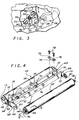
- Figure 4 is an enlarged perspective view, partially shown in exploded form, of a roller assembly forming the delivery system of the present invention, and illustrating the assembly prior to mounting in the press of Fig. 1;
- Figure 5 is an enlarged fragmentary perspeotive view, partially in cut away cross-section, of one end of a roller forming part of the assembly shown in Fig. 4; and
- Figure 6 is a side elevational view of a modified roller assembly of the present invention.
- As shown in the exemplary drawings, the present invention is embodied in a new and improved transfer device, generally designated in Fig. 3 by the
reference numeral 10, for supporting a printedsheet 12 during transfer of the sheet by the delivery system of a sheet-fed, off-set rotary printing press 14 of the type employing a one and one half to one delivery system. In this instance, illustrated in Figs. 1 and 2, is a conventional sheet-fed, off-set rotary press 14 such as that made by A.B. Dick, Co. under its model number 360 and which is shown with a conventional prior art one and one half to one delivery system designated generally by thereference numeral 16. The press 14, which is schematically illustrated herein for simplicity, includes asheet feeder station 18 whereinindividual sheets 12 to be printed are stacked and fed sequentially into the press, and a printing station 20 comprising aplate cylinder 22, ablanket cylinder 24, and animpression cylinder 26 havingsheet grippers 28 for gripping and holding the sheet during movement through the printing station. Thedelivery system 16 functions to pull the freshly printedsheet 12 from theimpression cylinder 26 and to convey the sheet to either another printing station or to adelivery station 30 as herein shown, where the printed sheets are stacked for removal from the press 14. - In a press 14 of the type employing a prior art one and one half to one
delivery system 16, the delivery system includes askeleton wheel 32 mounted on arotary drive shaft 34 extending laterally across the press adjacent theimpression cylinder 26, and which functions as a transfer device to support the freshly printed side of thesheet 12 during transfer of the sheet from the impression cylinder. To remove a freshly printedsheet 12 from theimpression cylinder 26 and pull the sheet to the next station, thedelivery system 16 has a pair of parallel endless drivenconveyor chains 36 trained around sprocket wheels 38 mounted on the lateral ends of thedrive shaft 34, and which carry laterally disposedgripper bars 40 havinggrippers 42 for gripping the leading edge of the printed sheet adjacent the impression cylinder. As shown herein, thegripper bars 40 include a conventional cam operated mechanism (not shown) for causing thegrippers 42 to open and close to grip the leading edge of asheet 12 as the gripper bar passes theimpression cylinder 26. To actuate the cam operated mechanism of thegrippers 42, acam plate 44 is attached to one of a pair of laterally spaced press frame supports 46, herein the right support as seen in Fig. 2, the supports being disposed laterally inwardly of theconveyor chains 36 and serving to support the lateral end portions of thedrive shaft 34 which is journaled therethrough. As thegripper bar 40 passes over thecam plate 44, the cam plate actuates the cam operating mechanism to open and close thegrippers 42 at the appropriate position to grip and pull asheet 12 from theimpression cylinder 26. - The
gripper bars 40 are longitudinally spaced along theconveyor chains 36 such that thedrive shaft 34, and hence the sprocket wheels 38 andskeleton wheel 32, will make one and one half complete revolutions between each passage of onegripper bar 40 past theimpression cylinder 26. In this manner, the drive shaft will make one and one half revolutions during transfer of eachindividual sheet 12 from theimpression cylinder 26. A rotary press 14 having this type of delivery system is conventionally known in the printing industry as a press having one and one half to one delivery system. - With conventional presses 14 having a prior art one and one half to one
delivery system 16, it is not possible to use a cylindrical roller concentrically mounted on thedrive shaft 34 such as disclosed in the before mentioned DeMoore Patent Nos. 3,791,644 and 4,402,267 since thegripper bars 40 must be able to pass around the periphery of the skeleton wheel at two diametrically spaced locations due to the one and one half to one delivery system cycle. Prior to the present invention, it was typical that prior art one and one half to onedelivery systems 16 use one or more segmentedskeleton wheels 32 having two diametrically opposedopenings 48 for permitting thegripper bars 40 to pass around the skeleton wheel adjacent the outer periphery of theimpression cylinder 26 as eachsheet 12 was transferred. - In an effort to minimize marking and smearing of the freshly printed
sheet 12 during transfer from theimpression cylinder 26 in such priorart delivery systems 16, the segmentedskeleton wheel 32 is adjustably mounted to thedrive shaft 34 so that the skeleton wheel can be laterally positioned along the drive shaft as shown by the phantom line positions illustrated in Fig. 2, to attempt to place the area of contact of the skeleton wheel outer periphery on the sheet where minimum wet ink is present. Thus, for each particular printing job, the position of theskeleton wheel 32 in priorart delivery systems 16 was required to be adjusted in an attempt to minimize sheet marking and marring, thereby requiring that the press 14 be stopped between each job. In many printing situations, it is not possible to position the segmentedskeleton wheel 32 in a position where it will not contact wet ink, and thesheet 12 will be marked or marred regardless of where the skeleton wheel is positioned. Moreover, in an effort to further reduce marking, priorart delivery systems 16 typically employskeleton wheels 32 having outerperipheral edges 50 which are relatively narrow, or even sharp for reducing the area over which the skeleton wheel contacts thesheet 12. Thenarrow edge 50 of priorart skeleton wheels 32 have been found to cause depressions in the freshly printed surface of thesheet 12, and may cause sheet creasing or tearing due to the uneven and very small support area afforded by the outer peripheral edge of the skeleton wheel. - In accordance with a primary aspect of the present invention, the new and improved
transfer device 10 eliminates the need for skeleton wheel adjustment between the printing jobs, and substantially eliminates any sheet marking and marring of the freshly printedsheet 12 while providing uniform and effective support for the freshly printed sheet over substantially its full width during transfer from theimpression cylinder 26 of the press 14. Further, the present invention provides atransfer device 10 which is highly reliable and effective in use, and which is relatively economical to manufacture and easy to install and maintain in place of priorart skeleton wheels 32 found in existing presses 14 without requiring any press modification. - Toward the foregoing ends, as best shown in Figs. 3 and 4, the
transfer device 10 of the present invention includes a plurality ofindividual rollers 52, herein two such rollers, formed as continuouscylindrical shells 54 mounted bystub axles 56 to anelongated frame 58 secured to thedrive shaft 34 for rotation therewith, and which engage and support the wet ink surface of thesheet 12 across substantially the full width of the sheet. As best seen in Fig. 4, theframe 58, which preferably is made of metal, herein is formed to have a generally "C" shaped cross-section defined by generally flatparallel side walls 60 and a generallyflat bottom wall 62, the side walls and bottom wall defining anelongated channel 64 dimensioned to receive thedrive shaft 34. To mount therollers 52 to theframe 58, a pair ofend plates 66 are secured, herein bybolts 68, to each of the ends of the frame, the length of the frame and end plates being dimensioned to fit along thedrive shaft 34 within the lateral space between the press frame supports 46. - The
end plates 66 are each provided with generally "C"shaped slots 70 formed centrally therein and which are aligned with thechannel 64 of theframe 58 for receiving thedrive shaft 34. Each of theend plates 66 forms a pair ofmounting flanges 72 which project outwardly from opposite sides of theslot 64 beyond theside walls 60 of theframe 58, and to which thestub axles 56 of therollers 52 are coupled. For rigidly mounting theframe 58 to thedrive shaft 34, a series ofclamps 74, herein three in number and formed as rectangular brackets having "C" shapedopenings 76 in each end through whichbolts 78 extended, are secured to theframe side walls 60 over the open end of thechannel 64 to securely clamp the drive shaft within the channel. With this arrangement theframe 58 androllers 52 can be quickly and easily installed on thedrive shaft 34 without requiring any modification in the press 14. - As can best be seen in Figs. 4 and 5, the
rollers 52 are releasably mounted to theflanges 72 of theframe 58 for free rotation by thestub axles 56 which project axially from each end of each roller and which are received inelongated slots 80 formed on diametrically opposed sides of thedevice shaft 34 in opposed ends of the flanges so that the axis of each roller is parallel with the axis of thedrive shaft 34. With particular reference to Fig. 5, thestub axle 56 at each end of therollers 52 comprises acylindrical shaft 82 having anouter end 84 projecting beyond the end of theshell 54, and aninner end 86 extending inside the shell, and is coupled to the shell by a support 88 herein formed as a doughnut shaped block having an outerperipheral surface 90 secured to the inner cylindrical surface of the shell, and an innerperipheral surface 92 spaced radially outwardly of the shaft. The inner end portion of eachstub axle 56 is journaled to the support block 88 through aroller bearing assembly 94 comprising aninner race 96 engaged with the outer periphery of theshaft 82, anouter race 98 seated within arecess 100 formed in the innerperipheral surface 92 of the support block, and a plurality ofroller bearings 102 disposed between the races to permit theshell 54 to rotate freely relative to the stub axle. - For releasably mounting the
rollers 52 to theframe 58, thestub axles 56 are spring loaded so that they can be quickly and easily removed from the mountingflanges 72. Disposed inwardly of theouter end 84 of theshaft 82 is anenlarged diameter collar 104 of circular cross-section, against the inner side of which abuts one end of acompression spring 106 encircling the shaft, the opposite end of the spring abutting against theinner race 96 to bias the shaft axially outwardly from the end of theroller 52. To prevent thestub axle 56 from being completely withdrawn from theroller 52, theinner end 86 of theshaft 82 has a disc shaped stop 108 formed thereon which has a diameter larger than that of theinner surface 92 of the support block 88 and which will abut against the block to prevent theshaft 82 from being removed. - When installed in the
frame 58, thestub axle 56 projects outwardly through theslots 80 in theflanges 72 with thecollar 104 frictionally engaged against the flange under the bias of thespring 106. To insure that thecollar 104 does not slip against theflange 72 and allow theroller 52 to come off the flange, acircular recess 110 having a diameter substantially equal to that of the collar is formed in the flange adjacent the closed end of theslot 80. In order to remove theroller 52 from theframe 58, all that is necessary is to depress theouter end 84 of one of thestub axles 56, as indicated by thearrow 112 of Fig. 5, and move the stub axle to the phantom line position shown to release thecollar 104 from therecess 110, and then slide theshaft 82 outwardly along theslot 80 until the roller is free of the frame. - To prevent marking and marring of the freshly printed
sheet 12 during operation of the press 14, theshell 54 of each of therollers 52 is made as a right circular cylinder, preferably of metal or plastic, having a continuous outerperipheral surface 114 coated with a low-friction, self lubricating material such as polytetrafluoroethylene, and is loosely covered with afabric material 116, such as is more particularly described in the above noted DeMoore Patent No. 4,402,267. In accordance with another important aspect of the present invention, the fabric covering 116, which preferably is made of a loosely woven material such as cheesecloth and impregnated with a liquid repellant substance such as that sold under the trademark "Scotchguard" manufactured by the 3M Company of Minneapolis, Minnesota, is formed as a seamless cylindrical-shaped sleeve havingopen ends 118, and which can be quickly and easily slipped over theroller shell 54 for removal and replacement. - To releasably attach the
fabric sleeve 116 to eachroller 52, theends 118 of the sleeve are folded over the ends of the shell and pressed inside the shell, preferably against afastener strip 120 such as that sold under the trademark VELCRO, disposed around the inner periphery of the shell adjacent the ends. Thefasteners 120 grip and hold the fabric sleeve ends 118, and endcaps 122, herein formed as cup shaped members having enlarged radial flanged outer ends 124 and bottoms 126 formed with acentral opening 128 for receiving thestub axle 56 therethrough, are press fit into the ends of theshell 54 to firmly clamp the ends of the fabric within the shell. With this arrangement, should it be necessary to replace thefabric sleeve 116 of aroller 52, such as may be required if the fabric has become soiled or torn, all that is necessary is that the roller be removed from theframe 58 and the end caps 122 pulled from the ends of theshell 54. Thesleeve 116 can then be pulled from thefastener 120, slid off theroller 52 and a new sleeve pulled over theshell 54 and the ends inserted into the ends of the shell and secured against thefasteners 120 with theend caps 122. Theroller 52 with thenew sleeve 116 can then be quickly and simply replaced in theframe 58 and the press 14 is ready for continued use. - With the
transfer device 10 of the present invention, it has been found that marking and marring of freshly printed sheets is substantially eliminated. Due to the free rotation mounting of therollers 52 to theframe 58, and difference in the speed of rotation of thetransfer device 10 relative to theimpression cylinder 26 is automatically compensated by rotation of the roller relative to the frame. Thus, as a freshly printedsheet 12 is pulled from theimpression cylinder 26 into engagement with aroller 52, the sheet wall immediately attached to the fabric covering 116 and the roller can rotate about itsstub axles 56 to prevent any relative movement of the sheet with respect to the fabric covered surface of theshell 54, thereby preventing marking and marring of the wet ink sheet surface. Moreover, since therollers 52 extend across the full width of thesheet 12, uniform and effective support for the sheet over a substantial area of contact is provided. - In Fig. 6 is illustrated a modified
frame 68′ for supporting fourrollers 52 in atransfer device 10 of the invention, parts of the modified frame having a common function with those of theframe 68 of the embodiment shown in Figs. 3-5 being designated by corresponding primed reference numerals. As shown in Fig. 6, the modifiedframe 58′, which has an elongated generally C-shaped appearance including anelongated channel 64′ formed byelongated side walls 60′ and abottom wall 62′, has a pair ofend plates 66′ (only one of which is shown), and which permit tworollers 52 to be releasably mounted to eachflange 72′. Theflange 72′ project outwardly from opposed sides of thechannel 64′ within which thedrive shaft 34 is mounted, and include fourelongated slots 80′ for receiving and retaining thestub axles 56 of therollers 52, each pair of slots in one flange being diametrically opposed across thedrive shaft 34 from the corresponding slots in the other flange. With this embodiment, sufficient space is still provided for passage of thegripper bar 40 each one and one half revolutions of thedrive shaft 34, but more support area is provided for thesheet 12 since four fabric coveredrollers 52 will engage and support the sheet during each revolution of thetransfer device 10. - From the foregoing, it should be apparent that the new and
improved transfer device 10 of the present invention can be quickly and easily installed in the delivery system of presses 14 of the type having a one and one half to one delivery system in place of the priorart skeleton wheels 32 without requiring press modification, and when so installed, will provide uniform support for freshly printedsheets 12 over a broad area of contact yet substantially prevent marking and marring of the wet ink. Further, with thetransfer device 10 of the present invention, it will no longer be necessary to stop the press 14 to adjust the position ofskeleton wheels 32, and the press can be operated continuously without danger of marking or marring regardless of the type of print job being done. Should it become necessary to replace a fabric covering 116 on anyroller 52, replacement can be quickly and easily accomplished without requiring the press 14 to stop for prolonged periods of time. - As illustrated herein, the axes of the
rollers 52 are aligned along a diametrical plane passing through the center of the axis of rotation of thedrive shaft 34, and the rollers are spaced outwardly from theside walls 60 of the frame a distance sufficient to permit the rollers to freely rotate about theirstub axles 56. It should be appreciated that although two and four roller embodiments have been herein illustrated, thetransfer device 10 of the present invention may employ additional rollers by appropriately modifying theend plates 66 for support of additional rollers, the critical parameters being that the axis of rotation of each roller be parallel with the axis rotation of thedrive shaft 34, and that the spacing of the roller about theframe 58 be sufficient to permit the gripper bars 40 to pass between the rollers adjacent theimpression cylinder 26.
Claims (18)
- A transfer device (10) for use in a sheet fed rotary printing press (14) of the type including an impression cylinder (26) for printing a sheet (12), a sheet delivery system (16) including a drive shaft (34) for transferring the printed sheet (12) from the impression cylinder (26) to another processing station within the press, said drive shaft (34) being driven by conveyor chains (36) between which at least one gripper bar (40) is laterally disposed, said transfer device being characterised by:
a frame (58) adapted for connection to said drive shaft, (34) and
at least two rollers (52) coupled to said frame (58) in an operative position for supporting said printed sheet (12) during transfer, said rollers (52) each being mounted for free rotation about axes parallel to an axis of rotation of said drive shaft (34), said rollers (52) being circumferentially spaced with respect to each other and radially spaced with respect to said drive shaft (34) in the operative position such that a spacing of said rollers (52) on said frame (58) is sufficient to permit said at least one gripper bar (40) to pass between said rollers (52) adjacent said impression cylinder (26). - A transfer device (10) as set forth in claim 1 further characterised by releasable mounting means (56, 106) coupling each of said rollers (52) to said frame (58).
- A transfer device (10) as set forth in claims 1 or 2 further characterised by an outer surface (114) of said roller (52) which is coated with a low friction material and is covered by a fabric material (116) impregnated with a liquid repellant substance.
- A transfer device (10) as set forth in any one of claims 1 - 3 further characterised in that each of said rollers (52) comprises a generally hollow, cylindrical shell (54) having open ends and axle means (56) for coupling said shell (54) to said frame (58), said shell (54) being coupled to said axle means (56) by bearing means (94) for permitting said shell (54) to rotate freely with respect to said axle means (56).
- A transfer device (10) as set forth in claim 4 further characterised in that said fabric covering (116) is formed as a seamless tubular sleeve having open ends (118).
- A transfer device (10) as set forth in claim 5 further characterised in that the open ends (118) of the fabric sleeve (116) are folded into the ends of said shell (54) and a pair of end caps (122) are press fit into the ends of said shell (54) to retain said sleeve (116) on said shell (54).
- A transfer devices (10) as set forth in any one of claims 4 - 6 further characterised in that said axle means (56) comprises a pair of stub axles (56) having inner end portions (86) disposed within said shell (54) and outer end portions (84) project outwardly form each end of said shell (54), the inner end portions (86) being journaled through said bearing means (96) and axially shiftable between extended and retracted positions relative thereto such that the outer end portions may be retracted inwardly with respect to said shell (54) for release of said roller (52) from said frame (58).
- A transfer device (10) as set forth in claim 7 further characterised by a compression spring (106) coupled between each stub axle (56) and the bearing means (96) for biasing each stub axle (56) toward the extended position.
- A transfer device (10) as set forth in claim 8 further characterised in that said frame (58) comprises an elongated, generally C-shaped frame extending laterally along said drive shaft (34), said frame (58) having lateral ends (66) defining a pair of diametrically disposed mounting flanges (72) for mounting said rollers (52) therebetween.
- A transfer device (10) as set forth in claim 9 further characterised in that each of said mounting flanges (72) includes an opening (76) for receiving the outer end portion (84) of said stub axle (56), said rollers (52) being removable from said frame (58) by retracting said outer end portion (84) against the bias of said spring (106) to disengaged said stub axle (56) from said opening (76).
- A transfer device (10) as set forth in any one of claims 7 - 10 further characterised in that said bearing means (94) comprises an inner bearing race (96) surrounding said inner end portion (86) of each of said stub axles (56) and an outer bearing race (98) coupled to said shell (54), said inner and outer bearing races (96, 98) being coupled by bearing elements (102) for relative rotation.
- A transfer device (10) as set forth in claim 1 further characterised in that each roller (52) includes:
a right circular cylindrical shell (54) having open ends, and forming a continuous outer peripheral support surface (114);
a low friction coating disposed on said support surface (114); and
a tubular sleeve (116) comprised of a fabric material disposed over said coated support surface (114). - A transfer device (10) as set forth in claim 12, further characterised in that said tubular sleeve (116) comprises a seamless cylindrical sleeve having open ends (118) formed of a woven fabric material, said sleeve (116) having an internal diameter of a size sufficient to permit said sleeve (116) to be loosely disposed about said roller (52).
- A transfer device (10) as set forth in claim 13 further characterised in that said woven fabric material is impregnated with a liquid repellant substance.
- A transfer device (10) as set forth in claims 13 or 14 further characterised in that said woven fabric material is a loosely woven cloth.
- A transfer device (10) as set forth in any of the preceding claims further characterised in that two of said rollers (52) are mounted on said frame (58).
- A transfer device (10) as set forth in any one of claims 1 - 15 further characterised in that four of said rollers (52) are mounted on said frame (58).
- A transfer device (10) as set forth in any one of the preceding claims further characterised in that at least two of said rollers (52) are diametrically opposed with respect to each other.
Applications Claiming Priority (2)
| Application Number | Priority Date | Filing Date | Title |
|---|---|---|---|
| US07/390,379 US4977828A (en) | 1989-08-07 | 1989-08-07 | Transfer roller device for printing presses |
| US390379 | 1989-08-07 |
Publications (3)
| Publication Number | Publication Date |
|---|---|
| EP0412236A2 EP0412236A2 (en) | 1991-02-13 |
| EP0412236A3 EP0412236A3 (en) | 1991-08-07 |
| EP0412236B1 true EP0412236B1 (en) | 1995-10-18 |
Family
ID=23542241
Family Applications (1)
| Application Number | Title | Priority Date | Filing Date |
|---|---|---|---|
| EP90101733A Expired - Lifetime EP0412236B1 (en) | 1989-08-07 | 1990-01-29 | Transfer roller device for printing presses and fabric material therefor |
Country Status (6)
| Country | Link |
|---|---|
| US (1) | US4977828A (en) |
| EP (1) | EP0412236B1 (en) |
| JP (1) | JP2628777B2 (en) |
| CA (1) | CA1329225C (en) |
| DD (1) | DD293989A5 (en) |
| DE (1) | DE69023070T2 (en) |
Families Citing this family (19)
| Publication number | Priority date | Publication date | Assignee | Title |
|---|---|---|---|---|
| DE69033028T2 (en) * | 1989-09-18 | 1999-09-16 | Canon K.K., Tokio/Tokyo | Rotatable conveyor element for an ink printing device |
| US5053826A (en) * | 1990-12-21 | 1991-10-01 | Xerox Corporation | Transfer loop synchronization in recirculating color printers |
| US5335596A (en) * | 1991-08-30 | 1994-08-09 | Howard W. DeMoore | Coating apparatus for sheet-fed, offset rotary printing presses |
| US5176077A (en) * | 1991-08-30 | 1993-01-05 | Howard W. DeMoore | Coating apparatus for sheet-fed, offset rotary printing presses |
| DE4131887C1 (en) * | 1991-09-25 | 1993-01-07 | Man Roland Druckmaschinen Ag, 6050 Offenbach, De | |
| DE19516066C2 (en) * | 1995-05-04 | 1999-09-09 | Heidelberger Druckmasch Ag | Sheet-guiding drum, in particular delivery drum, of a sheet-fed rotary printing machine |
| US5630363A (en) | 1995-08-14 | 1997-05-20 | Williamson Printing Corporation | Combined lithographic/flexographic printing apparatus and process |
| US5979322A (en) * | 1996-05-07 | 1999-11-09 | Demoore; Howard Warren | Environmentally safe, ink repellent, anti-marking flexible jacket covering having alignment stripes, centering marks and pre-fabricated reinforcement strips for attachment onto transfer cylinders in a printing press |
| US5713138A (en) * | 1996-08-23 | 1998-02-03 | Research, Incorporated | Coating dryer system |
| JP2001233491A (en) * | 2000-02-24 | 2001-08-28 | Murata Mach Ltd | Automatic sheet carrying device |
| JP4185658B2 (en) * | 2000-10-31 | 2008-11-26 | 富士フイルム株式会社 | Sheet body guide mechanism |
| CN100519186C (en) * | 2004-07-27 | 2009-07-29 | 海德堡印刷机械股份公司 | Machine for processing sheet made of printing carriers |
| JP4887133B2 (en) * | 2006-12-21 | 2012-02-29 | 株式会社リコー | Image forming apparatus |
| US8505908B2 (en) * | 2010-04-13 | 2013-08-13 | J&L Group International, Llc | Sheet deceleration apparatus and method |
| ES2671726T3 (en) | 2011-08-04 | 2018-06-08 | Alliance Machine Systems International, Llc | Apparatus and method for stacking corrugated sheet material |
| EP2840047B1 (en) | 2011-12-28 | 2018-05-09 | Alliance Machine Systems International, LLC | Apparatus and method for stacking items |
| EP3054183B1 (en) | 2013-10-04 | 2020-03-25 | Susumu Shoji | Roller covered with covering comprising woven fabric, and apparatus employing same |
| CN105939947B (en) | 2013-11-16 | 2018-10-16 | 三和技术株式会社 | It is covered with the roller for the covering being made of knitted fabric and the device using the roller |
| CN114013171A (en) * | 2021-10-22 | 2022-02-08 | 江阴市嘉铭印刷包装机械有限公司 | Air suspension type reverse printing device |
Family Cites Families (15)
| Publication number | Priority date | Publication date | Assignee | Title |
|---|---|---|---|---|
| US2085845A (en) * | 1934-09-19 | 1937-07-06 | Carborundum Co | Printing apparatus |
| US2940387A (en) * | 1958-08-21 | 1960-06-14 | Harris Intertype Corp | Sheet delivery means for rotary printing press |
| US3334892A (en) * | 1965-08-04 | 1967-08-08 | Adamovske Strojirny Np | Drum for delivering paper sheets from machines |
| US3602140A (en) * | 1970-02-09 | 1971-08-31 | Ralph E Sudduth | Rotary antismut device having radially adjustable sheet-supporting wheels |
| US3710470A (en) * | 1970-09-03 | 1973-01-16 | Kimberly Clark Co | Jacketed press roll |
| US3780925A (en) * | 1972-10-10 | 1973-12-25 | N Ternes | Retractable wheel for paper guiding cylinder |
| US4028783A (en) * | 1975-03-26 | 1977-06-14 | King Label Company | Idler roll for printing press drying stage |
| DE2550721C3 (en) * | 1975-11-12 | 1986-07-31 | M.A.N.- Roland Druckmaschinen AG, 6050 Offenbach | Transfer drum on a printing machine |
| US4098631A (en) * | 1976-08-18 | 1978-07-04 | Eastman Kodak Company | Method for manufacturing a compliant roller for use in an electrographic apparatus |
| JPS5553548Y2 (en) * | 1978-11-29 | 1980-12-11 | ||
| US4402267A (en) * | 1981-03-11 | 1983-09-06 | Printing Research Corporation | Method and apparatus for handling printed sheet material |
| JPS58128027U (en) * | 1982-02-25 | 1983-08-30 | 小森印刷機械株式会社 | Paper cylinder of sheet-fed rotary printing press |
| US4593480A (en) * | 1983-02-07 | 1986-06-10 | Siemens Aktiengesellschaft | Paper deflection roller for a printer or copier means functioning on the principle of electrophotography |
| FR2587274B3 (en) * | 1985-09-16 | 1987-10-30 | Mareels Gerard | ANTIMACULATING DEVICE FOR TRANSPORTING PRINTED TAPE |
| US4722276A (en) * | 1986-08-01 | 1988-02-02 | Tyler Jack D | Air blast for preventing contact of wet ink sheets with printing press delivery mechanisms |
-
1989
- 1989-08-07 US US07/390,379 patent/US4977828A/en not_active Expired - Lifetime
- 1989-09-29 CA CA000615021A patent/CA1329225C/en not_active Expired - Fee Related
-
1990
- 1990-01-29 EP EP90101733A patent/EP0412236B1/en not_active Expired - Lifetime
- 1990-01-29 DE DE69023070T patent/DE69023070T2/en not_active Expired - Fee Related
- 1990-01-30 DD DD90337388A patent/DD293989A5/en unknown
- 1990-07-18 JP JP2190373A patent/JP2628777B2/en not_active Expired - Fee Related
Also Published As
| Publication number | Publication date |
|---|---|
| EP0412236A3 (en) | 1991-08-07 |
| US4977828A (en) | 1990-12-18 |
| EP0412236A2 (en) | 1991-02-13 |
| CA1329225C (en) | 1994-05-03 |
| DE69023070T2 (en) | 1996-06-20 |
| JPH0371848A (en) | 1991-03-27 |
| DD293989A5 (en) | 1991-09-19 |
| JP2628777B2 (en) | 1997-07-09 |
| DE69023070D1 (en) | 1995-11-23 |
Similar Documents
| Publication | Publication Date | Title |
|---|---|---|
| US4977828A (en) | Transfer roller device for printing presses | |
| US6269743B1 (en) | Vacuum transfer apparatus for rotary sheet-fed printing presses | |
| US5176077A (en) | Coating apparatus for sheet-fed, offset rotary printing presses | |
| US4815379A (en) | Sheet transfer cylinder between printing units of a rotary printing machine | |
| US3548747A (en) | Web-fed rotary printing press | |
| US5127329A (en) | Vacuum transfer apparatus for rotary sheet-fed printing presses | |
| US4236814A (en) | Transport system for advancing copy sheets through tandem duplicating system | |
| US3642274A (en) | Sheet-supporting assembly for an inverter roll | |
| US8677899B2 (en) | Reversible anti-marking jackets and methods of using | |
| EP0433545B1 (en) | Net cartridge assembly for use with transfer and delivery cylinders in rotary printing presses | |
| JP2567157B2 (en) | Marking prevention method and apparatus for use with a double-sided printing cylinder of a rotary sheet-fed press | |
| US5243909A (en) | Vacuum transfer apparatus for rotary sheet-fed printing presses | |
| CN113646175A (en) | Device for fixing roller sheath | |
| EP0301128B1 (en) | Skeleton wheels and methods for attaching webs thereto | |
| US7168699B2 (en) | Sheet-processing machine with a sheet brake | |
| US4563950A (en) | Rotary printing machine with paper guide | |
| US3735700A (en) | Tire ring drive for label printers | |
| US4836104A (en) | Sheet transfer mechanism for a freshly printed sheet | |
| US4967656A (en) | Eccentric cylinder for sheet-fed rotary printing presses | |
| US4039832A (en) | Apparatus for thermographic duplication of information comprising a curve or cam member for axial movement of dye carrier | |
| US5779372A (en) | Hot stamp imprinting system with locking cam reel hubs | |
| US20230174334A1 (en) | Flexible jacket with ink marking zone identification indicator | |
| JPH0325914Y2 (en) | ||
| JPH02139240A (en) | Fouling-preventive cloth web mounting method and device | |
| JPH09300593A (en) | Printer |
Legal Events
| Date | Code | Title | Description |
|---|---|---|---|
| PUAI | Public reference made under article 153(3) epc to a published international application that has entered the european phase |
Free format text: ORIGINAL CODE: 0009012 |
|
| AK | Designated contracting states |
Kind code of ref document: A2 Designated state(s): CH DE FR GB IT LI SE |
|
| 17P | Request for examination filed |
Effective date: 19901227 |
|
| PUAL | Search report despatched |
Free format text: ORIGINAL CODE: 0009013 |
|
| AK | Designated contracting states |
Kind code of ref document: A3 Designated state(s): CH DE FR GB IT LI SE |
|
| 17Q | First examination report despatched |
Effective date: 19930818 |
|
| GRAA | (expected) grant |
Free format text: ORIGINAL CODE: 0009210 |
|
| AK | Designated contracting states |
Kind code of ref document: B1 Designated state(s): CH DE FR GB IT LI SE |
|
| REF | Corresponds to: |
Ref document number: 69023070 Country of ref document: DE Date of ref document: 19951123 |
|
| REG | Reference to a national code |
Ref country code: CH Ref legal event code: NV Representative=s name: PATENTANWALTSBUREAU R. A. MASPOLI |
|
| ET | Fr: translation filed | ||
| ITF | It: translation for a ep patent filed | ||
| PLBE | No opposition filed within time limit |
Free format text: ORIGINAL CODE: 0009261 |
|
| STAA | Information on the status of an ep patent application or granted ep patent |
Free format text: STATUS: NO OPPOSITION FILED WITHIN TIME LIMIT |
|
| 26N | No opposition filed | ||
| REG | Reference to a national code |
Ref country code: GB Ref legal event code: IF02 |
|
| PGFP | Annual fee paid to national office [announced via postgrant information from national office to epo] |
Ref country code: SE Payment date: 20020103 Year of fee payment: 13 Ref country code: FR Payment date: 20020103 Year of fee payment: 13 Ref country code: DE Payment date: 20020103 Year of fee payment: 13 |
|
| PGFP | Annual fee paid to national office [announced via postgrant information from national office to epo] |
Ref country code: GB Payment date: 20020104 Year of fee payment: 13 |
|
| PGFP | Annual fee paid to national office [announced via postgrant information from national office to epo] |
Ref country code: CH Payment date: 20020107 Year of fee payment: 13 |
|
| PG25 | Lapsed in a contracting state [announced via postgrant information from national office to epo] |
Ref country code: GB Free format text: LAPSE BECAUSE OF NON-PAYMENT OF DUE FEES Effective date: 20030129 |
|
| PG25 | Lapsed in a contracting state [announced via postgrant information from national office to epo] |
Ref country code: SE Free format text: LAPSE BECAUSE OF NON-PAYMENT OF DUE FEES Effective date: 20030130 |
|
| PG25 | Lapsed in a contracting state [announced via postgrant information from national office to epo] |
Ref country code: LI Free format text: LAPSE BECAUSE OF NON-PAYMENT OF DUE FEES Effective date: 20030131 Ref country code: CH Free format text: LAPSE BECAUSE OF NON-PAYMENT OF DUE FEES Effective date: 20030131 |
|
| PG25 | Lapsed in a contracting state [announced via postgrant information from national office to epo] |
Ref country code: DE Free format text: LAPSE BECAUSE OF NON-PAYMENT OF DUE FEES Effective date: 20030801 |
|
| EUG | Se: european patent has lapsed | ||
| REG | Reference to a national code |
Ref country code: CH Ref legal event code: PL |
|
| GBPC | Gb: european patent ceased through non-payment of renewal fee | ||
| PG25 | Lapsed in a contracting state [announced via postgrant information from national office to epo] |
Ref country code: FR Free format text: LAPSE BECAUSE OF NON-PAYMENT OF DUE FEES Effective date: 20030930 |
|
| REG | Reference to a national code |
Ref country code: FR Ref legal event code: ST |
|
| PG25 | Lapsed in a contracting state [announced via postgrant information from national office to epo] |
Ref country code: IT Free format text: LAPSE BECAUSE OF NON-PAYMENT OF DUE FEES;WARNING: LAPSES OF ITALIAN PATENTS WITH EFFECTIVE DATE BEFORE 2007 MAY HAVE OCCURRED AT ANY TIME BEFORE 2007. THE CORRECT EFFECTIVE DATE MAY BE DIFFERENT FROM THE ONE RECORDED. Effective date: 20050129 |