EP0411847B1 - An on-line drying control method for powdered or granular materials and a system to execute the method - Google Patents
An on-line drying control method for powdered or granular materials and a system to execute the method Download PDFInfo
- Publication number
- EP0411847B1 EP0411847B1 EP90308308A EP90308308A EP0411847B1 EP 0411847 B1 EP0411847 B1 EP 0411847B1 EP 90308308 A EP90308308 A EP 90308308A EP 90308308 A EP90308308 A EP 90308308A EP 0411847 B1 EP0411847 B1 EP 0411847B1
- Authority
- EP
- European Patent Office
- Prior art keywords
- materials
- heat treatment
- chamber
- moisture content
- treatment chamber
- Prior art date
- Legal status (The legal status is an assumption and is not a legal conclusion. Google has not performed a legal analysis and makes no representation as to the accuracy of the status listed.)
- Expired - Lifetime
Links
- 238000001035 drying Methods 0.000 title claims abstract description 51
- 239000008187 granular material Substances 0.000 title claims abstract description 29
- 239000012254 powdered material Substances 0.000 title claims abstract description 29
- 238000000034 method Methods 0.000 title claims abstract description 10
- 239000000463 material Substances 0.000 claims abstract description 140
- 238000010438 heat treatment Methods 0.000 claims abstract description 77
- 239000011261 inert gas Substances 0.000 claims description 24
- 239000007789 gas Substances 0.000 claims description 23
- 238000005070 sampling Methods 0.000 claims description 9
- 238000001514 detection method Methods 0.000 claims description 8
- 238000002347 injection Methods 0.000 claims description 6
- 239000007924 injection Substances 0.000 claims description 6
- 239000011347 resin Substances 0.000 description 10
- 229920005989 resin Polymers 0.000 description 10
- 238000010276 construction Methods 0.000 description 6
- 229910010293 ceramic material Inorganic materials 0.000 description 5
- 238000010586 diagram Methods 0.000 description 5
- XNWFRZJHXBZDAG-UHFFFAOYSA-N 2-METHOXYETHANOL Chemical compound COCCO XNWFRZJHXBZDAG-UHFFFAOYSA-N 0.000 description 3
- 238000001914 filtration Methods 0.000 description 3
- 238000004448 titration Methods 0.000 description 3
- 238000005443 coulometric titration Methods 0.000 description 2
- 230000000694 effects Effects 0.000 description 2
- 238000000465 moulding Methods 0.000 description 2
- 229910001120 nichrome Inorganic materials 0.000 description 2
- IJGRMHOSHXDMSA-UHFFFAOYSA-N Atomic nitrogen Chemical compound N#N IJGRMHOSHXDMSA-UHFFFAOYSA-N 0.000 description 1
- 239000004429 Calibre Substances 0.000 description 1
- BQCADISMDOOEFD-UHFFFAOYSA-N Silver Chemical compound [Ag] BQCADISMDOOEFD-UHFFFAOYSA-N 0.000 description 1
- 238000004458 analytical method Methods 0.000 description 1
- 239000000919 ceramic Substances 0.000 description 1
- 238000007796 conventional method Methods 0.000 description 1
- 238000003869 coulometry Methods 0.000 description 1
- 230000007547 defect Effects 0.000 description 1
- 229910001873 dinitrogen Inorganic materials 0.000 description 1
- 238000001704 evaporation Methods 0.000 description 1
- 230000008020 evaporation Effects 0.000 description 1
- 239000011521 glass Substances 0.000 description 1
- 239000001307 helium Substances 0.000 description 1
- 229910052734 helium Inorganic materials 0.000 description 1
- SWQJXJOGLNCZEY-UHFFFAOYSA-N helium atom Chemical compound [He] SWQJXJOGLNCZEY-UHFFFAOYSA-N 0.000 description 1
- 229910010272 inorganic material Inorganic materials 0.000 description 1
- 239000011147 inorganic material Substances 0.000 description 1
- 239000002655 kraft paper Substances 0.000 description 1
- 238000005259 measurement Methods 0.000 description 1
- 230000000717 retained effect Effects 0.000 description 1
- 229910052709 silver Inorganic materials 0.000 description 1
- 239000004332 silver Substances 0.000 description 1
- 238000011144 upstream manufacturing Methods 0.000 description 1
- 239000011800 void material Substances 0.000 description 1
- 238000003221 volumetric titration Methods 0.000 description 1
- 238000004804 winding Methods 0.000 description 1
Images


Classifications
-
- F—MECHANICAL ENGINEERING; LIGHTING; HEATING; WEAPONS; BLASTING
- F26—DRYING
- F26B—DRYING SOLID MATERIALS OR OBJECTS BY REMOVING LIQUID THEREFROM
- F26B25/00—Details of general application not covered by group F26B21/00 or F26B23/00
- F26B25/22—Controlling the drying process in dependence on liquid content of solid materials or objects
-
- G—PHYSICS
- G05—CONTROLLING; REGULATING
- G05D—SYSTEMS FOR CONTROLLING OR REGULATING NON-ELECTRIC VARIABLES
- G05D22/00—Control of humidity
- G05D22/02—Control of humidity characterised by the use of electric means
Definitions
- the present invention relates to an on-line drying control method for powdered or granular materials including inorganic materials such as resin and ceramic wherein materials stored and dried in a drying means such as a hopper dryer are automatically sampled and the moisture content thereof measured, and the temperature of the drying means is controlled based on the obtained result.
- the invention also relates to an on-line drying control system for said materials.
- resin materials before being fed into the hopper dryer are apt to absorb moisture in the air while stored in a silo or tank for a period of time after a kraft bag or a flexible container which is used to carry the resin materials is opened. Accordingly a fixed heating temperature and a fixed heating time are settled for the hopper dryer based on an estimated moisture content of resin materials. But such a conventional method for drying resin materials by the use of hopper dryer leaves further room for improvement in saving labour to achieve the most appropriate drying method as the heating of materials is controlled based on an estimation without sufficiently understanding the conditions of resin materials before they are heated.
- An object of the present invention is to provide an on-line drying control method for powdered or granular materials wherein a fixed amount of materials is automatically sampled, the moisture content thereof is by feeding into a moisture measuring/operating station and the temperature of drying means is controlled based on the obtained moisture content, and to provide an on-line drying control system for materials to execute the method efficiently.
- an on-line drying control method for powdered or granular materials wherein the moisture content of the materials is detected and set at predetermined value by executing the following steps repetitively each time a fixed amount of materials is sampled, characterized by the steps of:
- an on-line drying control system for powdered or granular materials wherein materials stored in a drying unit having a heating means is controlled so as to have a predetermined value of moisture content by sampling a fixed volumetric amount of materials stored in said drying unit, characterized in that said system comprises:
- the system further comprises a materials measuring chamber with a level detection sensor for detecting the stored amount of materials under said valve and a supplementary control damper disposed between said materials measuring chamber and said heat treatment chamber, wherein said materials stored in said drying unit are sampled and measured with said supplementary damper closed.
- the system may include a pressurized transport means including a pressurized gas injection port connecting said material discharge port of said drying unit with said heat treatment chamber via said valve; the powdered or granular materials in said drying unit being sampled and pneumatically transported to said heat treatment chamber by pressurized transport means.
- a pressurized transport means including a pressurized gas injection port connecting said material discharge port of said drying unit with said heat treatment chamber via said valve; the powdered or granular materials in said drying unit being sampled and pneumatically transported to said heat treatment chamber by pressurized transport means.
- the system may include a pressurized transport means connecting the materials discharge port of said drying unit with said materials measuring chamber having the level detection sensor via said valve, and a pressurized gas injection port in said pressurized transport means, and the powdered or granular materials in said drying unit are sampled and pneumatically transported to said measuring chamber by said pressurized transport means.
- a moisture measuring/operating station in accordance with the invention may use a moisture measuring unit which executes a coulometric titration, a volumetric titration or a simple absorptive photometric titration which has been disclosed in Japanese Patent Application 63-039291, Karl Fischer reagent being used for all those methods.
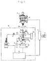
- the system shown in Figure 1 employs a transporting means wherein powdered or granular materials stored and dried in a hopper dryer A provided as a drying means are sampled by a rotary valve 8a constructing a material sampling means 8A and supplied by gravitational fall into a moisture measuring/operating station B .
- the moisture measuring/operating station B is constructed such that a heat treatment chamber 3 made of a heat-resistant glass provided with a heating means 4 at its periphery is disposed under the rotary valve 8a and the valve 8a and the heat chamber 3 are connected by a transport pipe P1 having a control valve 7a to control the material supply and a vent valve 7b to open to atmosphere, the control valve 7a including a highly airtight valve disc to prevent the leakage of moisture produced when the materials are heated in the chamber 3.
- a material discharge port 3b provided under the chamber 3 is provided with a solenoid-operated control damper 5 which opens and closes the port 3b by reciprocating a valve disc 5a and a weight measuring unit 2 is provided under the damper 5.
- the weight measuring unit 2 is equipped with a receiver 21 which can open and close to receive the heated materials discharged from the port 3b of heat chamber 3. When the materials are received in the receiver 21, the weight is automatically measured and is converted into an electrical signal at a signal processor 2a of measuring unit 2, the converted data being sent to a calculating unit 10.
- the heat treatment chamber 3 has a capacity enough to contain one sample of powdered or granular materials measured by the rotary valve 8a and its upper part is connected with a branch pipe P2 having a control valve 1a and leading to a moisture measuring unit 1.
- a highly accurate coulometric or volumetric moisture measurement by means of Karl Fischer reagent can be achieved by supplying the moisture evaporated by heating the materials into the unit 1 together with an inert gas and by inputting the weight of materials before they are heated.
- the moisture measuring unit 1 in this embodiment executes a coulometric titration.
- the value titrated and analyzed by the unit 1 is converted into an electrical signal and sent to the calculating unit 10, as is the weight value measured by the weight measuring unit 2.
- the value titrated and analyzed by the moisture measuring unit 1 and the weight value measured by the weight measuring unit 2 are input into the calculating unit 10, the moisture content being calculated and sent to a temperature controller C .
- the controller C is provided with a setting device 11 to set the most appropriate value for the moisture content of materials by a dial or push-button operation, whereby the moisture content of materials to be dried is controlled.
- the controller C compares the obtained moisture content with the moisture content settled by the settling device 11, reads a data table prepared in advance for controlling temperature and controls the temperature of drying means A such as a hopper dryer by sending a control signal into a heating part 12 so as to compensate for deviation of the measured moisture content from the required value.
- An inert gas feed port 6a is provided at the lower part of the heat chamber 3 in the moisture station B and connected through a control valve 6b to a gas source 6 which feeds an inert gas such as a dried nitrogen gas or helium gas.
- the heat treatment chamber 3 is equipped with a heating means 4 at its periphery constructed by Nesa electrodes or a well-known Nichrome wire. If the heating means is constructed by Nesa electrodes, the materials in the heat chamber 3 can be seen through and also the body of chamber 3 can be made thin and compact.
- the heat treatment chamber 3 is heated to and maintained at a temperature just below that at which the stored materials are vaporized in order to evaporate all the moisture contained in the materials.
- a temperature control unit 4a sets and controls the most appropriate temperature of the chamber 3 before containing materials depending on the materials to be heated therein.
- the damper 5 when sampling is required, the damper 5 is shut and the control valve 1a is closed to close the branch pipe P2 leading to the moisture measuring unit 1.
- the control valve 7a and the vent valve 7b are opened and the rotary valve 8a is driven in rotation while an inert gas is introduced into the chamber 3 by opening the control valve 6b, samples thus being supplied into the chamber 3.
- the vent valve 7b is opened to atmosphere to prevent air from entering into the chamber 3.
- control valve 7a and the vent valve 7b are closed with the damper 5 still closed.
- the control valve 1a is opened to open the branch pipe P2 leading to the moisture measuring unit 1 while the control valve 6b is opened to introduce an inert gas from the lower part of chamber 3 into all over the inside thereof.
- powdered or granular materials are heated in the chamber 3 and the moisture produced by the evaporation of heated materials is supplied into the moisture measuring unit 1 together with the introduced inert gas.
- a display 10a of calculating unit 10 shows a sign indicating the end of titration.
- the materials in the chamber 3 are supplied into the weight measuring unit 2 by opening the control damper 5.
- the materials received at the receiver 21 are weighed and the value is converted into an electrical signal by the signal processor 2a then sent to the calculating unit 10, wherein data sent from the moisture measuring unit 1 and the weight measuring unit 2 are calculated and the obtained moisture content of the materials is monitored and shown on the display 10a of calculating unit 10.
- the moisture content of sampled materials thus calculated in the calculating unit 10 is sent to the temperature controller C in the form of electrical signal and compared with the moisture content settled by the setting device 11.
- a heat control signal to compensate the deviation of two moisture contents is sent to the heating part 12 of drying means A. Consequently, the materials in the drying means A are heated and dried so as to get the moisture content settled by the setting device 11.
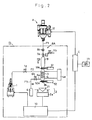
- Figure 2 shows a schematic diagram showing another preferable embodiment according to the present invention.
- a rotary valve 8b in a material supply means 8A of moisture measuring/operating station B does not work as a measuring device.
- a fixed amount of powdered or granular materials is weighed by a material measuring chamber 9 having a detection sensor S to detect the level of materials and provided between the material supply means 8A and a heat treatment chamber 3.
- Materials are supplied into the material measuring chamber 9 by opening a control valve 7a until the sensor S detects that supplied materials reach a determined level. After a fixed amount of materials is stored in the chamber 9, the materials are supplied into the heat chamber 3 by opening a first control damper 51 provided between the measuring chamber 9 and the heat chamber 3.
- a second control damper 52 to discharge the heated materials and a weight measuring unit 2 are provided under the heat treatment chamber 3, the heated materials to be titrated and analyzed being weighed by the measuring unit 2.
- a calculating unit 10 calculates data sent from a moisture measuring unit 1 and the weight measuring unit 2 and indicates the obtained moisture content of the materials on its display 10a. And other constructions are the same as the above-mentioned first system.
- Figure 3 is a schematic diagram showing still another preferable embodiment according to the present invention.
- This system is characterised by a pneumatic transporting means 81 having an injection nozzle equipped at a discharge port provided at the lower part of a hopper dryer A as a drying means. Powdered or granular materials are taken out of the hopper dryer A by feeding a pressurized gas into the transporting means 81 and supplied through a transport pipe line P4 by a pneumatic transportation into a moisture measuring/operating station B .
- the numeral 83 indicates a unit to dehumidify and dry a gas to be supplied into the hopper dryer A .
- the materials pneumatically transported by a pressurized gas by the use of such a transporting means 81 are separated from the gas by a filtering device 14 provided at the entrance of measuring chamber 9 of moisture measuring/operating station B .
- a capacitance level sensor S is provided with the measuring chamber 9 as a weight detection sensor, the sensor S controlling open and close operations of a control valve 7a to store a fixed amount of materials in the chamber 9.
- a fixed amount of materials stored in the chamber 9 falls into a heat treatment chamber 3 by opening a first control damper 51 to be stored therein.
- an inert gas introduced from a feed port 6a provided at the lower part of the heat chamber 3 is bled to atmosphere from the filtering device 14 passing through the heat chamber 3 and the measuring chamber 9. Therefore, both chambers 3 and 9 are prevented from entering of outer air and can be kept under dried circumstances which are suitable for titrating and analysing moisture content.
- the pneumatic transporting means 81 includes the pressurized gas injection nozzle provided at the initial end side of discharge port of hopper dryer (gas source side) and materials are sucked by injecting a pressurized gas from the nozzle by operating the gas source (not illustrated), that is well known as an ejecting effect.
- Such a pneumatic transporting means 81 has been already disclosed in Japan by the present applicant. Materials stored in the hopper A are taken out into the transport pipe line P4 and transported pneumatically when a pressurized gas injected from the nozzle creates negative pressure at the discharge port side of hopper A by the effect of ejection.
- This transporting means 81 is free from clogging caused at the beginning of suction operation because the apparent area of suction port becomes larger than that of a conventional suction nozzle having the same calibre, whereby a small amount of materials can be pneumatically transported by the use of a thin transport pipe.
- the system in Figure 3 is also characterized by including a material storing chamber 13 to store at least more than one sample of materials provided under the heat treatment chamber 3 in the moisture measuring/operating station B .
- a layer of powdered or granular materials to be heated is piled on a layer of materials stored in the storing chamber 13 and heated in the chamber 3. After the materials of upper layer are heated in the chamber 3, the materials in the storing chamber 13 are discharged by gravitational fall when a valve disc 52a of control damper 52 is opened.
- a level sensor S1 is provided with the storing chamber 13 as a weight detection sensor in order to control the amount of discharge, whereby immediately after one sample of materials is discharged, the valve disc 52a of damper 52 is closed, control valves 7a and 6b are opened and an inert gas is introduced into the chamber 13. At the same time a fixed amount of materials newly sampled by the pneumatic transporting means 81 is supplied into the heat treatment chamber 3.
- an inert gas is introduced into the heat chamber 3 by opening the control valve 6b when a new sample of materials is supplied. So, this system is more effective in bringing uniformity to the temperature in the heat chamber 3 because the inert gas works as a medium to transfer the heat of materials which have been already heated and also maintaining the temperature in the chamber 3.
- the weight of materials may be measured before heating by sampling a fixed amount of materials and feeding through the chamber 3 without executing heat treatment into the weight measuring unit 2.
- the average weight of sampled materials, which are not heated, taken out at a few times may be used as the weight data in order to consider the difference between both weights.
- Figure 4 illustrates the partially enlarged sectional view of another preferable construction of moisture measuring/operating station B .
- a pneumatic transporting means 81 is provided at a discharge port at the lower part of hopper dryer A constructing the drying means and the upstream end of a transport pipe line P4 extended from the transporting means 81 is connected to a feed port formed at the upper end of material measuring chamber 9 of material measuring/operating station B .
- the station B includes a heat treatment chamber 3 having a heating means 4 constructed by winding a Nichrome wire under the material measuring chamber 9 interposed by a first control damper 51, a material storing chamber 13, described heretofore, provided under the heat chamber 3, a second control damper 52 under the chamber 13, and a weight measuring unit 2 having a receiver 21 to receive powdered or granular materials discharged from a material discharge port 13b of the storing chamber 13 under the damper 52.
- Capacitance level sensors S and S1 are provided as a weight detection sensor for the measuring chamber 9 and the storing chamber 13 respectively.
- the transport pipe line P4 connected with the transporting means 81 at its downstream end is connected to the upper end of measuring chamber 9 and a filtering unit 14 to separate the transported materials from a pressurized gas is provided at the side of the chamber 9.
- the first control damper 51 provided between the measuring chamber 9 and the heat chamber 3 includes a solenoid-operated highly airtight valve disc 51a.
- the solenoid-operated second control damper 52 disposed under the storing chamber 13 is constructed so as to be able to introduce an inert gas by filling a breathable ceramic material 53 in a gas introduction pipe 54 even if a valve disc 52a is closed, as described hereinafter.
- the numeral 1a indicates a control valve interposed in the branch pipe P2 leading to a moisture measuring unit 1 (illustrated in Figure 3) from the upper part of heat treatment chamber 3.
- the temperature control of the drying means A is executed like the system shown in Figure 1.
- the temperature controller C s provided with the setting device 11 for moisture content, receiving the signal from the calculating unit 10 of moisture measuring/operating station B and sending a control signal to the heating part 12 of drying means A .
- valve disc 52a of control damper 52 is provided with a valve port 52b to discharge the materials and filled with the breathable ceramic material 53 so as to close a material discharge port 13b constructed under the heat chamber 3 when the valve disc 52a is at closed position.
- the gas introduction pipe 54 having one opened end is provided with the ceramic material 53 and the opening of the pipe 54 is connected with a gas feed pipe P3' leading to a pressurized and dried inert gas source 6'.
- valve port 52b conforms to the discharge port 13b when the damper 52 is opened, powdered or granular materials contained in the chamber 13 are discharged by gravitational fall through the port 13b.
- the ceramic material 53 closes the port 13b and prevents the discharge of materials.
- an inert gas entered from the gas introduction pipe 54 successively goes into the heat chamber 3 because the gas can pass through the ceramic material 53, thus the replacement by an inert gas, as described heretofore, and the supply of inert gas when materials are heated can be achieved.
- the system may be preferably constructed such that the volume of sampled materials is input into the calculating unit 10 automatically.
Landscapes
- Engineering & Computer Science (AREA)
- Physics & Mathematics (AREA)
- General Physics & Mathematics (AREA)
- Automation & Control Theory (AREA)
- Mechanical Engineering (AREA)
- General Engineering & Computer Science (AREA)
- Drying Of Solid Materials (AREA)
- Processing And Handling Of Plastics And Other Materials For Molding In General (AREA)
Abstract
Description
- The present invention relates to an on-line drying control method for powdered or granular materials including inorganic materials such as resin and ceramic wherein materials stored and dried in a drying means such as a hopper dryer are automatically sampled and the moisture content thereof measured, and the temperature of the drying means is controlled based on the obtained result. The invention also relates to an on-line drying control system for said materials.
- Generally, controlling the moisture content of resin materials has been considered a most important problem to overcome in order to maintain good quality of resin products, because an inappropriate moisture content of resin materials to be supplied into a molding machine causes defects in the products such as silver line or void. Therefore, resin materials are usually dried by the use of a hopper dryer before being supplied into the molding machine.
- However, resin materials before being fed into the hopper dryer are apt to absorb moisture in the air while stored in a silo or tank for a period of time after a kraft bag or a flexible container which is used to carry the resin materials is opened. Accordingly a fixed heating temperature and a fixed heating time are settled for the hopper dryer based on an estimated moisture content of resin materials. But such a conventional method for drying resin materials by the use of hopper dryer leaves further room for improvement in saving labour to achieve the most appropriate drying method as the heating of materials is controlled based on an estimation without sufficiently understanding the conditions of resin materials before they are heated.
- An object of the present invention is to provide an on-line drying control method for powdered or granular materials wherein a fixed amount of materials is automatically sampled, the moisture content thereof is by feeding into a moisture measuring/operating station and the temperature of drying means is controlled based on the obtained moisture content, and to provide an on-line drying control system for materials to execute the method efficiently.
- According to one aspect of the present invention, there is provided an on-line drying control method for powdered or granular materials wherein the moisture content of the materials is detected and set at predetermined value by executing the following steps repetitively each time a fixed amount of materials is sampled, characterized by the steps of:
- directly transporting the materials into a heat treatment chamber having a gastight heating means after sampling and measuring a fixed volumetric amount of materials stored in a drying unit associated with a temperature controller for controlling heating means in the drying unit;
- heating the materials in said heat treatment chamber while supplying the chamber with a pressurized and dried inert gas;
- titrating and analysing moisture generated by heating the materials in said heat treatment chamber by supplying the moisture, together with inert gas, to a moisture measuring unit;
- measuring the weight of the heated materials discharged from the chamber into a receiver of a weight measuring unit provided under said heat treatment chamber;
- automatically calculating the moisture content of said sampled materials by feeding the moisture value detected in said moisture measuring unit and the weight value measured in said weight measuring unit to a calculating unit;
- comparing a target predetermined moisture content with the moisture content output from said calculating unit in said temperature controller, by reference to a preprepared temperature control table; and
- executing feedback control of said heating means so that the moisture content of the materials becomes the target predetermined moisture content set in said temperature controller.
- According to another aspect of the invention, there is provided an on-line drying control system for powdered or granular materials wherein materials stored in a drying unit having a heating means is controlled so as to have a predetermined value of moisture content by sampling a fixed volumetric amount of materials stored in said drying unit, characterized in that said system comprises:
- a valve for sampling and measuring a fixed amount of powdered or granular materials stored in said drying unit;
- a heat treatment chamber having a gastight heating means and having sufficient capacity to contain the fixed amount of sampled materials, said heat treatment chamber being disposed under said valve;
- a transport pipe be; ween said valve and said heat treatment chamber, said transport pipe having a control valve to control supply of materials from said valve and having a gas vent valve for opening to atmosphere;
- a moisture measuring unit connecting to an upper part of said heat treatment chamber via a branch pipe having a control valve;
- a control damper disposed under said heat treatment chamber to discharge the materials stored in said heat treatment chamber;
- an inert gas feeding means having a feed port at a lower part of said heat treatment chamber and having a feed pipe incorporating a control valve for controlling introduction of pressurized and dried inert gas into said heat treatment chamber;
- a weight measuring unit disposed under said control damper for measuring the weight of the heated materials;
- a calculating unit which calculates the moisture content of the materials utilising the weight value of the heated materials obtained from said weight measuring unit and the moisture value from said moisture measuring unit each time a fixed amount of materials is sampled; and
- a temperature controller connected with said calculating unit for feedback control of said heating means, the moisture content of materials to be controlled being set as a target value in said temperature controller in advance, and said controller comparing the predetermined moisture content with the moisture content output from said calculating unit, with reference to a preprepared temperature control table, and executing feedback control of said heating means so that the moisture content of the materials stored in said drying unit becomes the target value set in said controller.
- Preferably, the system further comprises a materials measuring chamber with a level detection sensor for detecting the stored amount of materials under said valve and a supplementary control damper disposed between said materials measuring chamber and said heat treatment chamber, wherein said materials stored in said drying unit are sampled and measured with said supplementary damper closed.
- Moreover, the system may include a pressurized transport means including a pressurized gas injection port connecting said material discharge port of said drying unit with said heat treatment chamber via said valve; the powdered or granular materials in said drying unit being sampled and pneumatically transported to said heat treatment chamber by pressurized transport means.
- Alternatively, the system may include a pressurized transport means connecting the materials discharge port of said drying unit with said materials measuring chamber having the level detection sensor via said valve, and a pressurized gas injection port in said pressurized transport means, and the powdered or granular materials in said drying unit are sampled and pneumatically transported to said measuring chamber by said pressurized transport means.
- A moisture measuring/operating station in accordance with the invention may use a moisture measuring unit which executes a coulometric titration, a volumetric titration or a simple absorptive photometric titration which has been disclosed in Japanese Patent Application 63-039291, Karl Fischer reagent being used for all those methods.
- In the accompanying drawings:
- Figure 1 is a schematic diagram showing one preferable embodiment according to the present invention;
- Figure 2 is a schematic diagram showing another preferable embodiment according to the present invention;
- Figure 3 is a schematic diagram showing still another preferable embodiment according to the present invention; and
- Figure 4 illustrates the partially enlarged sectional view of another preferable construction of moisture measuring/operating station of the system.
- The system shown in Figure 1 employs a transporting means wherein powdered or granular materials stored and dried in a hopper dryer A provided as a drying means are sampled by a
rotary valve 8a constructing a material sampling means 8A and supplied by gravitational fall into a moisture measuring/operating station B. - In this system the moisture measuring/operating station B is constructed such that a
heat treatment chamber 3 made of a heat-resistant glass provided with a heating means 4 at its periphery is disposed under therotary valve 8a and thevalve 8a and theheat chamber 3 are connected by a transport pipe P1 having acontrol valve 7a to control the material supply and avent valve 7b to open to atmosphere, thecontrol valve 7a including a highly airtight valve disc to prevent the leakage of moisture produced when the materials are heated in thechamber 3. - A
material discharge port 3b provided under thechamber 3 is provided with a solenoid-operatedcontrol damper 5 which opens and closes theport 3b by reciprocating avalve disc 5a and aweight measuring unit 2 is provided under thedamper 5. Theweight measuring unit 2 is equipped with areceiver 21 which can open and close to receive the heated materials discharged from theport 3b ofheat chamber 3. When the materials are received in thereceiver 21, the weight is automatically measured and is converted into an electrical signal at asignal processor 2a ofmeasuring unit 2, the converted data being sent to a calculatingunit 10. - The
heat treatment chamber 3 has a capacity enough to contain one sample of powdered or granular materials measured by therotary valve 8a and its upper part is connected with a branch pipe P2 having acontrol valve 1a and leading to amoisture measuring unit 1. - Many kinds of trace moisture measuring unit, which use Karl Fischer reagent and the introduction port of which can be directly connected with the branch pipe P2, can be used as the
moisture measuring unit 1. If such a unit is provided, a highly accurate coulometric or volumetric moisture measurement by means of Karl Fischer reagent can be achieved by supplying the moisture evaporated by heating the materials into theunit 1 together with an inert gas and by inputting the weight of materials before they are heated. - The moisture measuring
unit 1 in this embodiment executes a coulometric titration. The value titrated and analyzed by theunit 1 is converted into an electrical signal and sent to the calculatingunit 10, as is the weight value measured by theweight measuring unit 2. Thus the value titrated and analyzed by themoisture measuring unit 1 and the weight value measured by theweight measuring unit 2 are input into the calculatingunit 10, the moisture content being calculated and sent to a temperature controller C. - The controller C is provided with a
setting device 11 to set the most appropriate value for the moisture content of materials by a dial or push-button operation, whereby the moisture content of materials to be dried is controlled. - After the moisture content of sampled materials is calculated in the calculating
unit 10, the controller C compares the obtained moisture content with the moisture content settled by thesettling device 11, reads a data table prepared in advance for controlling temperature and controls the temperature of drying means A such as a hopper dryer by sending a control signal into aheating part 12 so as to compensate for deviation of the measured moisture content from the required value. - An inert
gas feed port 6a is provided at the lower part of theheat chamber 3 in the moisture station B and connected through acontrol valve 6b to agas source 6 which feeds an inert gas such as a dried nitrogen gas or helium gas. - The
heat treatment chamber 3 is equipped with a heating means 4 at its periphery constructed by Nesa electrodes or a well-known Nichrome wire. If the heating means is constructed by Nesa electrodes, the materials in theheat chamber 3 can be seen through and also the body ofchamber 3 can be made thin and compact. - The
heat treatment chamber 3 is heated to and maintained at a temperature just below that at which the stored materials are vaporized in order to evaporate all the moisture contained in the materials. For this purpose, atemperature control unit 4a sets and controls the most appropriate temperature of thechamber 3 before containing materials depending on the materials to be heated therein. - According to this system, when sampling is required, the
damper 5 is shut and thecontrol valve 1a is closed to close the branch pipe P2 leading to themoisture measuring unit 1. At the same time thecontrol valve 7a and thevent valve 7b are opened and therotary valve 8a is driven in rotation while an inert gas is introduced into thechamber 3 by opening thecontrol valve 6b, samples thus being supplied into thechamber 3. At this time thevent valve 7b is opened to atmosphere to prevent air from entering into thechamber 3. - After a fixed amount of powdered or granular materials dried in the drying means is thus contained in the
chamber 3, thecontrol valve 7a and thevent valve 7b are closed with thedamper 5 still closed. Thecontrol valve 1a is opened to open the branch pipe P2 leading to themoisture measuring unit 1 while thecontrol valve 6b is opened to introduce an inert gas from the lower part ofchamber 3 into all over the inside thereof. - Under these conditions, powdered or granular materials are heated in the
chamber 3 and the moisture produced by the evaporation of heated materials is supplied into themoisture measuring unit 1 together with the introduced inert gas. - The supply of inert gas continues until the
measuring unit 1 detects the end of titration. When theunit 1 detects its end, a display 10a of calculatingunit 10 shows a sign indicating the end of titration. - After the heat treatment of powdered or granular materials is thus finished, the materials in the
chamber 3 are supplied into theweight measuring unit 2 by opening thecontrol damper 5. In theunit 2 the materials received at thereceiver 21 are weighed and the value is converted into an electrical signal by thesignal processor 2a then sent to the calculatingunit 10, wherein data sent from themoisture measuring unit 1 and theweight measuring unit 2 are calculated and the obtained moisture content of the materials is monitored and shown on the display 10a of calculatingunit 10. - The moisture content of sampled materials thus calculated in the calculating
unit 10 is sent to the temperature controller C in the form of electrical signal and compared with the moisture content settled by the settingdevice 11. A heat control signal to compensate the deviation of two moisture contents is sent to theheating part 12 of drying means A. Consequently, the materials in the drying means A are heated and dried so as to get the moisture content settled by the settingdevice 11. - Figure 2 shows a schematic diagram showing another preferable embodiment according to the present invention.
- In this system a
rotary valve 8b in a material supply means 8A of moisture measuring/operating station B does not work as a measuring device. A fixed amount of powdered or granular materials is weighed by amaterial measuring chamber 9 having a detection sensor S to detect the level of materials and provided between the material supply means 8A and aheat treatment chamber 3. - Materials are supplied into the
material measuring chamber 9 by opening acontrol valve 7a until the sensor S detects that supplied materials reach a determined level. After a fixed amount of materials is stored in thechamber 9, the materials are supplied into theheat chamber 3 by opening afirst control damper 51 provided between the measuringchamber 9 and theheat chamber 3. - A
second control damper 52 to discharge the heated materials and aweight measuring unit 2 are provided under theheat treatment chamber 3, the heated materials to be titrated and analyzed being weighed by the measuringunit 2. - A calculating
unit 10 calculates data sent from amoisture measuring unit 1 and theweight measuring unit 2 and indicates the obtained moisture content of the materials on its display 10a. And other constructions are the same as the above-mentioned first system. - Figure 3 is a schematic diagram showing still another preferable embodiment according to the present invention.
- This system is characterised by a pneumatic transporting
means 81 having an injection nozzle equipped at a discharge port provided at the lower part of a hopper dryer A as a drying means. Powdered or granular materials are taken out of the hopper dryer A by feeding a pressurized gas into the transportingmeans 81 and supplied through a transport pipe line P4 by a pneumatic transportation into a moisture measuring/operating station B. The numeral 83 indicates a unit to dehumidify and dry a gas to be supplied into the hopper dryer A. - The materials pneumatically transported by a pressurized gas by the use of such a transporting
means 81 are separated from the gas by afiltering device 14 provided at the entrance of measuringchamber 9 of moisture measuring/operating station B. A capacitance level sensor S is provided with the measuringchamber 9 as a weight detection sensor, the sensor S controlling open and close operations of acontrol valve 7a to store a fixed amount of materials in thechamber 9. - A fixed amount of materials stored in the
chamber 9 falls into aheat treatment chamber 3 by opening afirst control damper 51 to be stored therein. At this time an inert gas introduced from afeed port 6a provided at the lower part of theheat chamber 3 is bled to atmosphere from thefiltering device 14 passing through theheat chamber 3 and the measuringchamber 9. Therefore, bothchambers - The pneumatic transporting
means 81 according to this system includes the pressurized gas injection nozzle provided at the initial end side of discharge port of hopper dryer (gas source side) and materials are sucked by injecting a pressurized gas from the nozzle by operating the gas source (not illustrated), that is well known as an ejecting effect. - Such a pneumatic transporting
means 81 has been already disclosed in Japan by the present applicant. Materials stored in the hopper A are taken out into the transport pipe line P4 and transported pneumatically when a pressurized gas injected from the nozzle creates negative pressure at the discharge port side of hopper A by the effect of ejection. This transporting means 81 is free from clogging caused at the beginning of suction operation because the apparent area of suction port becomes larger than that of a conventional suction nozzle having the same calibre, whereby a small amount of materials can be pneumatically transported by the use of a thin transport pipe. - The system in Figure 3 is also characterized by including a
material storing chamber 13 to store at least more than one sample of materials provided under theheat treatment chamber 3 in the moisture measuring/operating station B. - A layer of powdered or granular materials to be heated is piled on a layer of materials stored in the storing
chamber 13 and heated in thechamber 3. After the materials of upper layer are heated in thechamber 3, the materials in the storingchamber 13 are discharged by gravitational fall when avalve disc 52a ofcontrol damper 52 is opened. A level sensor S1 is provided with the storingchamber 13 as a weight detection sensor in order to control the amount of discharge, whereby immediately after one sample of materials is discharged, thevalve disc 52a ofdamper 52 is closed,control valves chamber 13. At the same time a fixed amount of materials newly sampled by the pneumatic transportingmeans 81 is supplied into theheat treatment chamber 3. - According to this system in which the
material storing chamber 13 is provided under theheat treatment chamber 3, powdered or granular materials which have been already heated are stored in the storingchamber 13. Therefore, thechamber 3 is prevented from losing the heat by the supply of materials, contrary, the retained heat of materials can be applied to the above layer of materials, whereby an energy-saving system and quick analysis can be achieved. - Further according to this system, an inert gas is introduced into the
heat chamber 3 by opening thecontrol valve 6b when a new sample of materials is supplied. So, this system is more effective in bringing uniformity to the temperature in theheat chamber 3 because the inert gas works as a medium to transfer the heat of materials which have been already heated and also maintaining the temperature in thechamber 3. - Furthermore according to this system, the weight of materials may be measured before heating by sampling a fixed amount of materials and feeding through the
chamber 3 without executing heat treatment into theweight measuring unit 2. In this case, as the weight of the materials measured by the measuringunit 2 differs from that of heated materials, the average weight of sampled materials, which are not heated, taken out at a few times may be used as the weight data in order to consider the difference between both weights. - Figure 4 illustrates the partially enlarged sectional view of another preferable construction of moisture measuring/operating station B.
- A pneumatic transporting
means 81 is provided at a discharge port at the lower part of hopper dryer A constructing the drying means and the upstream end of a transport pipe line P4 extended from the transportingmeans 81 is connected to a feed port formed at the upper end ofmaterial measuring chamber 9 of material measuring/operating station B. - The station B includes a
heat treatment chamber 3 having a heating means 4 constructed by winding a Nichrome wire under thematerial measuring chamber 9 interposed by afirst control damper 51, amaterial storing chamber 13, described heretofore, provided under theheat chamber 3, asecond control damper 52 under thechamber 13, and aweight measuring unit 2 having areceiver 21 to receive powdered or granular materials discharged from amaterial discharge port 13b of the storingchamber 13 under thedamper 52. - Capacitance level sensors S and S1 are provided as a weight detection sensor for the measuring
chamber 9 and the storingchamber 13 respectively. The transport pipe line P4 connected with the transporting means 81 at its downstream end is connected to the upper end of measuringchamber 9 and afiltering unit 14 to separate the transported materials from a pressurized gas is provided at the side of thechamber 9. - The
first control damper 51 provided between the measuringchamber 9 and theheat chamber 3 includes a solenoid-operated highlyairtight valve disc 51a. The solenoid-operatedsecond control damper 52 disposed under the storingchamber 13 is constructed so as to be able to introduce an inert gas by filling a breathableceramic material 53 in agas introduction pipe 54 even if avalve disc 52a is closed, as described hereinafter. The numeral 1a indicates a control valve interposed in the branch pipe P2 leading to a moisture measuring unit 1 (illustrated in Figure 3) from the upper part ofheat treatment chamber 3. - The temperature control of the drying means A is executed like the system shown in Figure 1. For this purpose the temperature controller C s provided with the
setting device 11 for moisture content, receiving the signal from the calculatingunit 10 of moisture measuring/operating station B and sending a control signal to theheating part 12 of drying means A. - The
valve disc 52a ofcontrol damper 52 is provided with avalve port 52b to discharge the materials and filled with the breathableceramic material 53 so as to close amaterial discharge port 13b constructed under theheat chamber 3 when thevalve disc 52a is at closed position. Thegas introduction pipe 54 having one opened end is provided with theceramic material 53 and the opening of thepipe 54 is connected with a gas feed pipe P3' leading to a pressurized and dried inert gas source 6'. - According to such a construction, as the
valve port 52b conforms to thedischarge port 13b when thedamper 52 is opened, powdered or granular materials contained in thechamber 13 are discharged by gravitational fall through theport 13b. When thedamper 52 is closed, theceramic material 53 closes theport 13b and prevents the discharge of materials. However, an inert gas entered from thegas introduction pipe 54 successively goes into theheat chamber 3 because the gas can pass through theceramic material 53, thus the replacement by an inert gas, as described heretofore, and the supply of inert gas when materials are heated can be achieved. - In the above-mentioned embodiments a construction in which sampled materials are weighed before heating or after heating by the
weight measuring unit 2 is explained. However, such aweight measuring unit 2 may be removed and the apparent specific weight and the volume of sampled materials may be input into a calculatingunit 10. Such a system can further simplify the construction thereof because of the removal ofweight measuring unit 2 and is more effectively used for the moisture control of the same kind of powdered or granular materials. - In this case, the system may be preferably constructed such that the volume of sampled materials is input into the calculating
unit 10 automatically.
Claims (5)
- An on-line drying control method for powdered or granular materials wherein the moisture content of the materials is detected and set at predetermined value by executing the following steps repetitively each time a fixed amount of materials is sampled, characterized by the steps of:directly transporting the materials into a heat treatment chamber (3) having a gastight heating means (4) after sampling and measuring a fixed volumetric amount of materials stored in a drying unit (A) associated with a temperature controller (C) for controlling heating means (12) in the drying unit;heating the materials in said heat treatment chamber (3) while supplying the chamber with a pressurized and dried inert gas;titrating and analysing moisture generated by heating the materials in said heat treatment chamber (3) by supplying the moisture, together with inert gas, to a moisture measuring unit (1);measuring the weight of the heated materials discharged from the chamber (3) into a receiver (21) of a weight measuring unit (2) provided under said heat treatment chamber (3);automatically calculating the moisture content of said sampled materials by feeding the moisture value detected in said moisture measuring unit (1) and the weight value measured in said weight measuring unit (2) to a calculating unit (10);comparing a target predetermined moisture content with the moisture content output from said calculating unit (10) in said temperature controller (C), by reference to a preprepared temperature control table; andexecuting feedback control of said heating means (12) so that the moisture content of the materials becomes the target predetermined moisture content set in said temperature controller (C).
- An on-line drying control system for powdered or granular materials wherein materials stored in a drying unit (A) having a heating means (12) is controlled so as to have a predetermined value of moisture content by sampling a fixed volumetric amount of materials stored in said drying unit (A), characterized in that said system comprises:a valve (8a) for sampling and measuring a fixed amount of powdered or granular materials stored in said drying unit (A);a heat treatment chamber (3) having a gastight heating means (4) and having sufficient capacity to contain the fixed amount of sampled materials, said heat treatment chamber (3) being disposed under said valve (8a);a transport pipe (P1) between said valve (8a) and said heat treatment chamber (3), said transport pipe (P1) having a control valve (7a) to control supply of materials from said valve (8a) and having a gas vent valve (7b) for opening to atmosphere;a moisture measuring unit (1) connecting to an upper part of said heat treatment chamber (3) via a branch pipe (P2) having a control valve (1a);a control damper (5) disposed under said heat treatment chamber (3) to discharge the materials stored in said heat treatment chamber (3);an inert gas feeding means (6) having a feed port (6a) at a lower part of said heat treatment chamber (3) and having a feed pipe (P3) incorporating a control valve (6b) for controlling introduction of pressurized and dried inert gas into said heat treatment chamber (3);a weight measuring unit (2) disposed under said control damper (5) for measuring the weight of the heated materials;a calculating unit (10) which calculates the moisture content of the materials utilising the weight value of the heated materials obtained from said weight measuring unit (2) and the moisture value from said moisture measuring unit (1) each time a fixed amount of materials is sampled; anda temperature controller (C) connected with said calculating unit (10) for feedback control of said heating means (12), the moisture content of materials to be controlled being set as a target value in said temperature controller (C) in advance, and said controller (C) comparing the predetermined moisture content with the moisture content output from said calculating unit (10), with reference to a preprepared temperature control table, and executing feedback control of said heating means (12) so that the moisture content of the materials stored in said drying unit (A) becomes the target value set in said controller (C).
- An on-line drying control system for powdered or granular materials as set forth in claim 2, characterized in that said system further comprises a materials measuring chamber (9) with a level detection sensor (S) for detecting the stored amount of materials under said valve (8a) and a supplementary control damper (51) disposed between said materials measuring chamber (9) and said heat treatment chamber (3), wherein said materials stored in said drying unit (A) are sampled and measured with said supplementary damper (51) closed.
- An on-line drying control system for powdered or granular materials as set forth in claim 2, characterised by:
a pressurized transport means (81) including a pressurized gas injection port connecting said material discharge port of said drying unit (A) with said heat treatment chamber (3) via said valve (8a); the powdered or granular materials in said drying unit (A) being sampled and pneumatically transported to said heat treatment chamber (3) by pressurized transport means (81). - An on-line drying control system for powdered or granular materials as set forth in claim 3, characterized by:
a pressurized transport means (81) connecting the materials discharge port of said drying unit (A) with said materials measuring chamber (9) having the level detection sensor (S) via said valve (7a), and a pressurized gas injection port in said pressurized transport means (81), and the powdered or granular materials in said drying unit (A) are sampled and pneumatically transported to said measuring chamber (9) by said pressurized transport means (81).
Applications Claiming Priority (2)
| Application Number | Priority Date | Filing Date | Title |
|---|---|---|---|
| JP201050/89 | 1989-08-01 | ||
| JP1201050A JP2810885B2 (en) | 1989-08-01 | 1989-08-01 | On-line drying control method for granular material and on-line drying control system using this method |
Publications (3)
| Publication Number | Publication Date |
|---|---|
| EP0411847A2 EP0411847A2 (en) | 1991-02-06 |
| EP0411847A3 EP0411847A3 (en) | 1992-07-01 |
| EP0411847B1 true EP0411847B1 (en) | 1996-04-17 |
Family
ID=16434569
Family Applications (1)
| Application Number | Title | Priority Date | Filing Date |
|---|---|---|---|
| EP90308308A Expired - Lifetime EP0411847B1 (en) | 1989-08-01 | 1990-07-30 | An on-line drying control method for powdered or granular materials and a system to execute the method |
Country Status (6)
| Country | Link |
|---|---|
| US (1) | US5165180A (en) |
| EP (1) | EP0411847B1 (en) |
| JP (1) | JP2810885B2 (en) |
| AT (1) | ATE137034T1 (en) |
| CA (1) | CA2022387A1 (en) |
| DE (1) | DE69026549T2 (en) |
Families Citing this family (16)
| Publication number | Priority date | Publication date | Assignee | Title |
|---|---|---|---|---|
| JP2863860B2 (en) * | 1989-08-01 | 1999-03-03 | 三菱化学株式会社 | On-line moisture management system for granular materials |
| US6079122A (en) * | 1998-08-28 | 2000-06-27 | Rajkovich; Thomas Russell | Weighing dryer |
| US20080000215A1 (en) * | 2000-03-02 | 2008-01-03 | Duncan Ronnie J | Engine systems and methods |
| US6532804B2 (en) | 2001-05-15 | 2003-03-18 | Cliffs Mining Services Company | Method and apparatus for on-line moisture analysis of a concentrate |
| RU2200288C1 (en) * | 2001-07-05 | 2003-03-10 | Государственное образовательное учреждение Воронежская государственная технологическая академия | Method for automatic control of drying process |
| RU2239138C1 (en) * | 2003-02-11 | 2004-10-27 | Государственное образовательное учреждение Воронежская государственная технологическая академия | Method of automatic control of drying process |
| RU2276763C1 (en) * | 2004-10-15 | 2006-05-20 | Государственное образовательное учреждение высшего профессионального образования Воронежская государственная технологическая академия | Mode of automatic control of a drying process |
| RU2290583C1 (en) * | 2005-04-26 | 2006-12-27 | Государственное образовательное учреждение высшего профессионального образования Воронежская государственная технологическая академия | Method of automatic control of process of drying of dispersed materials under active hydrodynamic conditions |
| RU2298749C1 (en) * | 2005-11-30 | 2007-05-10 | Государственное образовательное учреждение высшего профессионального образования Воронежская государственная технологическая академия | Method and device for automatic control of drying |
| WO2015085634A1 (en) * | 2013-12-13 | 2015-06-18 | 长春吉大科学仪器设备有限公司 | Total-weight detection-based method and system thereof for on-line measuring and controlling moisture in circulation drying of grain |
| RU2664810C1 (en) * | 2017-03-13 | 2018-08-22 | Общество с ограниченной ответственностью "Научно-производственное предприятие ОКБА" (ООО "НПП ОКБА") | Regulator of gas humidity |
| CN107726833A (en) * | 2017-11-10 | 2018-02-23 | 重庆市贵金象炭黑有限责任公司 | A kind of drying system oxygen content coordinated control system and its method |
| DE102017126943A1 (en) * | 2017-11-16 | 2019-05-16 | Protec Polymer Processing Gmbh | Method and device for the automated monitoring of the moisture content of bulk plastic material |
| CN109654821B (en) * | 2018-12-28 | 2021-06-22 | 中核(天津)机械有限公司 | A drying device and drying method |
| CN112413895B (en) * | 2020-11-19 | 2021-12-07 | 苏州博墨热能产品有限公司 | Integrated plate type condensing boiler with variable flue size and flue changing method |
| CN113758219B (en) * | 2021-09-18 | 2022-10-21 | 骏能化工(龙南)有限公司 | Slurry waste recycling process |
Family Cites Families (13)
| Publication number | Priority date | Publication date | Assignee | Title |
|---|---|---|---|---|
| DE1946132A1 (en) * | 1969-09-11 | 1971-03-18 | Gimborn Probat Werke | Coffee grounds plant |
| US4043050A (en) * | 1973-07-04 | 1977-08-23 | Imperial Chemical Industries Limited | Drying plastics |
| US4022560A (en) * | 1975-12-29 | 1977-05-10 | Heinonen Russell M | Drying device |
| US4144012A (en) * | 1977-08-05 | 1979-03-13 | Pinkley Paul D | Material hopper translatable unit |
| US4302888A (en) * | 1979-02-26 | 1981-12-01 | Dickey-John Corporation | Rotary steam dryer control |
| JPS6050432B2 (en) * | 1983-11-15 | 1985-11-08 | 日本たばこ産業株式会社 | tobacco dryer |
| JPS60120182A (en) * | 1983-12-02 | 1985-06-27 | 日本たばこ産業株式会社 | Method of controlling temperature of drier |
| US4665629A (en) * | 1986-02-25 | 1987-05-19 | Susanne Cramer | Dryer for plastic granules |
| GB2195428A (en) * | 1986-09-26 | 1988-04-07 | Reekie Manufacturing | Batch dryer control system |
| US4773168A (en) * | 1986-12-24 | 1988-09-27 | Aec, Inc. | Thermal dryer for resin processing |
| US4838705A (en) * | 1987-06-08 | 1989-06-13 | Arizona Instrument Corporation | Apparatus for determining percent of moisture |
| US4896795A (en) * | 1988-01-15 | 1990-01-30 | Ediger Randall J | Grain moisture sensor |
| US4924601A (en) * | 1989-07-27 | 1990-05-15 | Bercaw Willis M | System for conditioning grain |
-
1989
- 1989-08-01 JP JP1201050A patent/JP2810885B2/en not_active Expired - Fee Related
-
1990
- 1990-07-26 US US07/557,864 patent/US5165180A/en not_active Expired - Lifetime
- 1990-07-30 DE DE69026549T patent/DE69026549T2/en not_active Expired - Fee Related
- 1990-07-30 AT AT90308308T patent/ATE137034T1/en not_active IP Right Cessation
- 1990-07-30 EP EP90308308A patent/EP0411847B1/en not_active Expired - Lifetime
- 1990-07-31 CA CA002022387A patent/CA2022387A1/en not_active Abandoned
Also Published As
| Publication number | Publication date |
|---|---|
| JPH0363110A (en) | 1991-03-19 |
| CA2022387A1 (en) | 1991-02-02 |
| DE69026549T2 (en) | 1996-09-19 |
| US5165180A (en) | 1992-11-24 |
| JP2810885B2 (en) | 1998-10-15 |
| DE69026549D1 (en) | 1996-05-23 |
| EP0411847A2 (en) | 1991-02-06 |
| ATE137034T1 (en) | 1996-05-15 |
| EP0411847A3 (en) | 1992-07-01 |
Similar Documents
| Publication | Publication Date | Title |
|---|---|---|
| EP0411847A2 (en) | An on-line drying control method for powdered or granular materials and a system to execute the method | |
| US5301440A (en) | On-line type moisture measuring system for powdered or granular materials | |
| EP0411848B1 (en) | An on-line moisture control method for powdered or granular materials and a system to execute the method | |
| US5670751A (en) | Bulk material weighing container with pressure feedback | |
| JPH03138217A (en) | Pneumatic type suction conveyor device | |
| US20020061232A1 (en) | Apparatus for conveying bulk material | |
| JP4084304B2 (en) | Method and apparatus for weight distribution of bulk material | |
| US12594724B2 (en) | Module for supplying additive manufacturing powder allowing drying of the powder | |
| JPH0526575A (en) | On-line drying control method, dry control system and on-line centralized moisture monitoring system for granular material | |
| JP2860823B2 (en) | Moisture vaporizer in moisture measuring device | |
| JP2958644B2 (en) | Powder material feeder | |
| US20240263874A1 (en) | Systems and processes for drying granular materials | |
| ES2029598A6 (en) | Feeder device of samples for vibrating tube electronic densimeters. | |
| JP2529404Y2 (en) | Vaporizer for moisture measurement device | |
| JPH02194349A (en) | Voluntary certification system for grain drying facilities | |
| JPS6182155A (en) | Grain moisture measuring device | |
| JPS618628A (en) | Scaling and packing device for grains | |
| JPH09203655A (en) | Apparatus and method for weighing in powder-and-granular-material storage facility | |
| JPH02214547A (en) | Exhaust device in grain sample packaging machine | |
| JPH02310444A (en) | Abnormality detector of self-calibration system for grain sample | |
| JPH06104201B2 (en) | Grain test dryer | |
| JPS5924235A (en) | Device for preparing gassy measuring sample | |
| JPH01293141A (en) | Equipment for carrying samples into the test dryer for self-inspection | |
| JPH0319943B2 (en) | ||
| JPH0659945U (en) | Bean weighing device |
Legal Events
| Date | Code | Title | Description |
|---|---|---|---|
| PUAI | Public reference made under article 153(3) epc to a published international application that has entered the european phase |
Free format text: ORIGINAL CODE: 0009012 |
|
| AK | Designated contracting states |
Kind code of ref document: A2 Designated state(s): AT CH DE FR GB IT LI NL |
|
| 17P | Request for examination filed |
Effective date: 19901228 |
|
| PUAL | Search report despatched |
Free format text: ORIGINAL CODE: 0009013 |
|
| AK | Designated contracting states |
Kind code of ref document: A3 Designated state(s): AT CH DE FR GB IT LI NL |
|
| 17Q | First examination report despatched |
Effective date: 19931216 |
|
| GRAH | Despatch of communication of intention to grant a patent |
Free format text: ORIGINAL CODE: EPIDOS IGRA |
|
| GRAA | (expected) grant |
Free format text: ORIGINAL CODE: 0009210 |
|
| ITF | It: translation for a ep patent filed | ||
| AK | Designated contracting states |
Kind code of ref document: B1 Designated state(s): AT CH DE FR GB IT LI NL |
|
| REF | Corresponds to: |
Ref document number: 137034 Country of ref document: AT Date of ref document: 19960515 Kind code of ref document: T |
|
| REG | Reference to a national code |
Ref country code: CH Ref legal event code: NV Representative=s name: PATENTANWALTSBUERO FELDMANN AG |
|
| REF | Corresponds to: |
Ref document number: 69026549 Country of ref document: DE Date of ref document: 19960523 |
|
| ET | Fr: translation filed | ||
| PLBE | No opposition filed within time limit |
Free format text: ORIGINAL CODE: 0009261 |
|
| STAA | Information on the status of an ep patent application or granted ep patent |
Free format text: STATUS: NO OPPOSITION FILED WITHIN TIME LIMIT |
|
| 26N | No opposition filed | ||
| PGFP | Annual fee paid to national office [announced via postgrant information from national office to epo] |
Ref country code: GB Payment date: 19980728 Year of fee payment: 9 |
|
| PGFP | Annual fee paid to national office [announced via postgrant information from national office to epo] |
Ref country code: NL Payment date: 19980730 Year of fee payment: 9 |
|
| PGFP | Annual fee paid to national office [announced via postgrant information from national office to epo] |
Ref country code: AT Payment date: 19980731 Year of fee payment: 9 |
|
| PGFP | Annual fee paid to national office [announced via postgrant information from national office to epo] |
Ref country code: DE Payment date: 19990719 Year of fee payment: 10 |
|
| PGFP | Annual fee paid to national office [announced via postgrant information from national office to epo] |
Ref country code: FR Payment date: 19990722 Year of fee payment: 10 |
|
| PG25 | Lapsed in a contracting state [announced via postgrant information from national office to epo] |
Ref country code: GB Free format text: LAPSE BECAUSE OF NON-PAYMENT OF DUE FEES Effective date: 19990730 Ref country code: AT Free format text: LAPSE BECAUSE OF NON-PAYMENT OF DUE FEES Effective date: 19990730 |
|
| PGFP | Annual fee paid to national office [announced via postgrant information from national office to epo] |
Ref country code: CH Payment date: 19991026 Year of fee payment: 10 |
|
| PG25 | Lapsed in a contracting state [announced via postgrant information from national office to epo] |
Ref country code: NL Free format text: LAPSE BECAUSE OF NON-PAYMENT OF DUE FEES Effective date: 20000201 |
|
| GBPC | Gb: european patent ceased through non-payment of renewal fee |
Effective date: 19990730 |
|
| NLV4 | Nl: lapsed or anulled due to non-payment of the annual fee |
Effective date: 20000201 |
|
| PG25 | Lapsed in a contracting state [announced via postgrant information from national office to epo] |
Ref country code: LI Free format text: LAPSE BECAUSE OF NON-PAYMENT OF DUE FEES Effective date: 20000731 Ref country code: CH Free format text: LAPSE BECAUSE OF NON-PAYMENT OF DUE FEES Effective date: 20000731 |
|
| REG | Reference to a national code |
Ref country code: CH Ref legal event code: PL |
|
| PG25 | Lapsed in a contracting state [announced via postgrant information from national office to epo] |
Ref country code: FR Free format text: LAPSE BECAUSE OF NON-PAYMENT OF DUE FEES Effective date: 20010330 |
|
| REG | Reference to a national code |
Ref country code: FR Ref legal event code: ST |
|
| PG25 | Lapsed in a contracting state [announced via postgrant information from national office to epo] |
Ref country code: DE Free format text: LAPSE BECAUSE OF NON-PAYMENT OF DUE FEES Effective date: 20010501 |
|
| PG25 | Lapsed in a contracting state [announced via postgrant information from national office to epo] |
Ref country code: IT Free format text: LAPSE BECAUSE OF NON-PAYMENT OF DUE FEES;WARNING: LAPSES OF ITALIAN PATENTS WITH EFFECTIVE DATE BEFORE 2007 MAY HAVE OCCURRED AT ANY TIME BEFORE 2007. THE CORRECT EFFECTIVE DATE MAY BE DIFFERENT FROM THE ONE RECORDED. Effective date: 20050730 |