EP0411273B1 - Osteosynthetic assembly with twist fixation plate - Google Patents
Osteosynthetic assembly with twist fixation plate Download PDFInfo
- Publication number
- EP0411273B1 EP0411273B1 EP90110558A EP90110558A EP0411273B1 EP 0411273 B1 EP0411273 B1 EP 0411273B1 EP 90110558 A EP90110558 A EP 90110558A EP 90110558 A EP90110558 A EP 90110558A EP 0411273 B1 EP0411273 B1 EP 0411273B1
- Authority
- EP
- European Patent Office
- Prior art keywords
- blade
- intramedullary nail
- nail
- retaining plate
- retaining
- Prior art date
- Legal status (The legal status is an assumption and is not a legal conclusion. Google has not performed a legal analysis and makes no representation as to the accuracy of the status listed.)
- Expired - Lifetime
Links
- 230000001097 osteosynthetic effect Effects 0.000 title description 12
- 210000000689 upper leg Anatomy 0.000 claims description 22
- 210000000988 bone and bone Anatomy 0.000 claims description 16
- 238000003780 insertion Methods 0.000 claims description 11
- 230000037431 insertion Effects 0.000 claims description 11
- 238000006073 displacement reaction Methods 0.000 claims description 2
- 206010017076 Fracture Diseases 0.000 description 9
- 210000002436 femur neck Anatomy 0.000 description 5
- 210000000501 femur body Anatomy 0.000 description 4
- 238000000034 method Methods 0.000 description 3
- 208000010392 Bone Fractures Diseases 0.000 description 2
- 230000000712 assembly Effects 0.000 description 2
- 238000000429 assembly Methods 0.000 description 2
- 238000002513 implantation Methods 0.000 description 2
- 239000000463 material Substances 0.000 description 2
- 206010016454 Femur fracture Diseases 0.000 description 1
- 206010020100 Hip fracture Diseases 0.000 description 1
- 208000001132 Osteoporosis Diseases 0.000 description 1
- 238000005452 bending Methods 0.000 description 1
- 238000010276 construction Methods 0.000 description 1
- 230000007812 deficiency Effects 0.000 description 1
- 239000007943 implant Substances 0.000 description 1
- 230000006641 stabilisation Effects 0.000 description 1
- 238000011105 stabilization Methods 0.000 description 1
Images


Classifications
-
- A—HUMAN NECESSITIES
- A61—MEDICAL OR VETERINARY SCIENCE; HYGIENE
- A61B—DIAGNOSIS; SURGERY; IDENTIFICATION
- A61B17/00—Surgical instruments, devices or methods
- A61B17/16—Instruments for performing osteoclasis; Drills or chisels for bones; Trepans
- A61B17/17—Guides or aligning means for drills, mills, pins or wires
- A61B17/1721—Guides or aligning means for drills, mills, pins or wires for applying pins along or parallel to the axis of the femoral neck
-
- A—HUMAN NECESSITIES
- A61—MEDICAL OR VETERINARY SCIENCE; HYGIENE
- A61B—DIAGNOSIS; SURGERY; IDENTIFICATION
- A61B17/00—Surgical instruments, devices or methods
- A61B17/56—Surgical instruments or methods for treatment of bones or joints; Devices specially adapted therefor
- A61B17/58—Surgical instruments or methods for treatment of bones or joints; Devices specially adapted therefor for osteosynthesis, e.g. bone plates, screws or setting implements
- A61B17/68—Internal fixation devices, including fasteners and spinal fixators, even if a part thereof projects from the skin
- A61B17/74—Devices for the head or neck or trochanter of the femur
- A61B17/742—Devices for the head or neck or trochanter of the femur having one or more longitudinal elements oriented along or parallel to the axis of the neck
- A61B17/744—Devices for the head or neck or trochanter of the femur having one or more longitudinal elements oriented along or parallel to the axis of the neck the longitudinal elements coupled to an intramedullary nail
Definitions
- This invention relates to an assembly for use in osteosynthesis according to the preamble of claim 1.
- the assembly according to the invention is used for the treatment of fractures of the femur which extend into the neck of the bone and which are generally more difficult to treat than fractures restricted to the shaft of the femur.
- an intramedullary nail having transverse holes at or near its head is inserted into the femur and then one or more screws are inserted angularly across the head of the intramedullary nail.
- Such a nail is shown, for example in EP-A 257,118.
- a similar device is disclosed in US-Patent No. 4,628,920 MATHYS showing an intramedullary nail with a longitudinal through-slot for receiving transverse wires or pins with the purpose of fixing the head of the intramedullary nail, i.e. in order to give rotational stability to the intramedullary nail inserted in the femur. All such prior art devices of this class have one deficiency or another. Some require extremely large or heavy screws; or where small transverse screws are employed the device does not provide adequate support.
- the invention as claimed is intended to remedy these drawbacks. It solves the problem of how to design an osteosynthetic assembly for reduction and stabilization of this type of difficult femur fractures which extend into the neck of the femur which is strong, light and relatively simple to implant.
- an osteosynthetic assembly for fixation of fractures of the femur which extend into the neck of the femur comprising the features of claim 1.
- the fixation plate used in the assembly according to the invention includes an outer retaining plate which can be attached, as by screws, to the lateral shank of the femur and a blade extending from the retaining plate and designed to extend into the neck of the femur.
- the blade is twisted helically about 90°,preferably in a continuous way and is adapted to movably pass trough a longitudinal slot in an intramedullary nail which has been driven into the shank of the femur.
- the longitudinal axis of the blade forms preferably an angle a in the range of 90 - 150° with the plane of the retaining plate and preferably carries a cannula for receiving a guide wire, such as a Kirschner wire.
- the retaining plate has one or more screw holes to accommodate screws for fastening the retaining plate to the intramedullary nail.
- the portion of the blade nearest to the retaining plate is preferably orthogonal to said retaining plate.
- the portion of the blade in the slot has its major dimension, W, preferably parallel to the longitudinal axis of the intramedullary nail, and the portion of the blade most remote from the retaining plate has its major dimension, W, preferably transverse to the longitudinal axis of the intramedullary nail.
- the fixation device is movably supported by the bottom wall of the slot of the intramedullary nail allowing the angular and/or longitudinal positioning of the helically twisted blade by the action of retaining screws inserted through the hole of the retaining plate for retaining firmly the fixation device to the intramedullary nail.
- the assembly according to the invention is useful for osteosynthetic treatment of intertrochanteric fractures and fractures of the neck of the femur. It may also be used to treat brittle bone, such as those caused by osteoporosis. Since smaller, lighter intramedullary nails may be used with this assembly, there is less damage to the rest of the bone. It is easier to remove than similar prior art assemblies. Furthermore, when this assembly is used, it is often unnecessary to ream out as much bone as is the case with the prior art devices. The same assembly may be used for treatment of fractures of either the left or right femur.
- the osteosynthetic assembly according to the invention is shown in Figs. 1 and 2.
- an intramedullary nail 17 is positioned in the medulla of a femur 18.
- the intramedullary nail 17 may be of any suitable design and material, although it is preferred to use an intramedullary nail 17 of the type shown and described in the US-Patent No. 4,628,920.
- the intramedullary nail 17 is provided with a slot 19 to accommodate the blade 12 of a fixation plate 10 and one or more through holes 26 to accommodate one or more retaining screws 27 inserted through screw hole 14 in the retaining plate 11. Additional screw holes (not shown) may be provided to permit transverse retaining screws or bolts (not shown) to be inserted at the distal end of the intramedullary nail 17.
- the fixation plate 10 as used in the assembly according to the invention comprises a retaining plate 11 which is adapted to lie along the lateral shaft of the femur 18 and a blade 12 which extends transversely to the plane of retaining plate 11.
- the axis 13 of the blade 12 forms an angle a with the plane of retaining plate 11 which may vary according to the individual patient, but which will in general be between about 90° and about 150°.
- the blade 12 is helically twisted around its axis 13, the total angular displacement being about 90°.
- the retaining plate 11 may be furnished with one or more screw holes 14 for fixing the retaining plate 11 to the lateral shaft of the femur 18.
- FIG. 4 and 4A A modified version of the fixation plate 10 is shown in Figs. 4 and 4A.
- the blade 15 of the fixation plate 10 may be provided with a cannula 16 for receiving a Kirschner guide wire or the like to facilitate insertion of the blade 15 into the bone, in the manner described below.
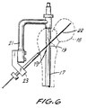
- FIG. 5 An intramedullary nail 17 having the structure shown in Figs. 1 and 2 has been inserted into the lateral shaft of a femur 18, in conventional manner. Attached to the intramedullary nail 17 is an insertion handle 21, a standard fixture used to insert intramedullary nails. Following emplacement of the intramedullary nail 17, as shown in Fig. 6, a Kirschner guide wire 22 may be inserted through the area of the fracture in the neck of the femur 18, passing through slot 19 in the intramedullary nail 17.
- the Kirschner guide wire 22 may be installed in a conventional manner using an alignment device 23, attached to the insertion handle 21 to ensure that it is placed at the proper angle.
- the Kirschner guide wire 22 extends from the exterior of the femur 18 through the bone across the fracture or fractures.
- the Kirschner guide wire 22 may then be used to guide the insertion of a chisel 24 into the bone 18 at the correct angle to cut a hole in the lateral side of the femur 18.
- the chisel 24 may be cannulated, as at 25, to ensure alignment with the Kirschner guide wire 22.
- Figure 8 shows the fixation plate 10 used in the assembly according to the invention about to be inserted into the fractured femur 18. If the blade 15 is cannulated, as shown in Figs. 4 and 4A, the cannula 16 of the fixation plate 10 is slid over the Kirschner guide wire 22 to ensure insertion of the fixation plate 10 at the correct angle. It is not necessary, however, to have such a cannula 16 on the blade 15 of the fixation plate 10.
- the blade 12 On the other hand, at the outer end of the blade 12, its major dimension, W, will be transverse to the axis of the intramedullary nail 17 and to the axis of the femur 18 in which it is inserted. Thus the blade 12 will give maximum support where it is actually needed.
- the blade 12 of the fixation plate 10 has a large surface area, yet the fixation plate 10 of the assembly according to the invention is less bulky than prior art devices. Consequently it is able to support even soft bone structure.
Landscapes
- Health & Medical Sciences (AREA)
- Surgery (AREA)
- Orthopedic Medicine & Surgery (AREA)
- Life Sciences & Earth Sciences (AREA)
- Heart & Thoracic Surgery (AREA)
- Veterinary Medicine (AREA)
- Engineering & Computer Science (AREA)
- Biomedical Technology (AREA)
- Nuclear Medicine, Radiotherapy & Molecular Imaging (AREA)
- Medical Informatics (AREA)
- Molecular Biology (AREA)
- Animal Behavior & Ethology (AREA)
- General Health & Medical Sciences (AREA)
- Public Health (AREA)
- Neurology (AREA)
- Dentistry (AREA)
- Oral & Maxillofacial Surgery (AREA)
- Surgical Instruments (AREA)
Description
- This invention relates to an assembly for use in osteosynthesis according to the preamble of
claim 1. - The assembly according to the invention is used for the treatment of fractures of the femur which extend into the neck of the bone and which are generally more difficult to treat than fractures restricted to the shaft of the femur.
- Various osteosynthetic assemblies have been used in the treatment of these difficult fractures.
- In one class of devices an intramedullary nail having transverse holes at or near its head is inserted into the femur and then one or more screws are inserted angularly across the head of the intramedullary nail. Such a nail is shown, for example in EP-A 257,118. A similar device is disclosed in US-Patent No. 4,628,920 MATHYS showing an intramedullary nail with a longitudinal through-slot for receiving transverse wires or pins with the purpose of fixing the head of the intramedullary nail, i.e. in order to give rotational stability to the intramedullary nail inserted in the femur.
All such prior art devices of this class have one deficiency or another. Some require extremely large or heavy screws; or where small transverse screws are employed the device does not provide adequate support. - Another known design is disclosed in US-Patent No. 3,025,853 MASON teaching the use of a twisted blade attached to a retaining plate for further attachment to the bone without implantation of an intramedullary nail. The retaining plate of this device is therefore not supported by or fixed to another osteosynthetic device, such as an intramedullary nail, and depends wholly on its attachment to the bone. This produces an unfavourably long lever arm (formed by the helically twisted blade) acting on the bone.
- Another known design is disclosed in US-Patent No. 4,103,683 NEUFELD which teaches the combined use of a femoral nail with a slot for receiving a fixation device, which includes a helically twisted blade. The fixation device is firmly seated in the slot by use of a set screw at a right angle with respect to the nail axis allowing no relative movement between the blade and the nail and no anatomically adequate positioning of the fixation device. Furthermore this design produces an unfavourably long lever arm (formed by the helically twisted blade) acting on the femoral nail.
- The invention as claimed is intended to remedy these drawbacks. It solves the problem of how to design an osteosynthetic assembly for reduction and stabilization of this type of difficult femur fractures which extend into the neck of the femur which is strong, light and relatively simple to implant.
- In a principle aspect it comprises an osteosynthetic assembly for fixation of fractures of the femur which extend into the neck of the femur comprising the features of
claim 1. - The fixation plate used in the assembly according to the invention includes an outer retaining plate which can be attached, as by screws, to the lateral shank of the femur and a blade extending from the retaining plate and designed to extend into the neck of the femur. The blade is twisted helically about 90°,preferably in a continuous way and is adapted to movably pass trough a longitudinal slot in an intramedullary nail which has been driven into the shank of the femur. The longitudinal axis of the blade forms preferably an angle a in the range of 90 - 150° with the plane of the retaining plate and preferably carries a cannula for receiving a guide wire, such as a Kirschner wire.
The retaining plate has one or more screw holes to accommodate screws for fastening the retaining plate to the intramedullary nail. The portion of the blade nearest to the retaining plate is preferably orthogonal to said retaining plate. - When said blade is positioned in the slot of the intramedullary nail the portion of the blade in the slot has its major dimension, W, preferably parallel to the longitudinal axis of the intramedullary nail, and the portion of the blade most remote from the retaining plate has its major dimension, W, preferably transverse to the longitudinal axis of the intramedullary nail.
The fixation device is movably supported by the bottom wall of the slot of the intramedullary nail allowing the angular and/or longitudinal positioning of the helically twisted blade by the action of retaining screws inserted through the hole of the retaining plate for retaining firmly the fixation device to the intramedullary nail. - The main advantages offered by the invention are the following:
- a) The assembly according to the invention comprises a blade which is not only firmly attached to the bone but which is additionally secured to the intramedullary nail. The resulting structure is both strong and light. By means of this construction the blade of the assembly according to the invention is able to transmit heavy loads both to the bone and to the intramedullary nail. Nevertheless, due to this stable structure, the blade can be designed in a very flat shape necessitating the removal of only a small volume of bone material upon insertion.
- b) In the invention the fixation device is actually fixed to the femur and is only movably supported by the bottom wall of the slot of the femoral nail allowing a precise angular and longitudinal positioning of the helically twisted blade by means of the retaining screws inserted through the screw holes of the retaining plate.
- c) The force distribution upon the several structural elements (blade/slot of nail/retaining plate/femoral shaft/retaining screw/femoral nail) in this complex osteosynthetic assembly is far superior to the prior art devices.
- The assembly according to the invention is useful for osteosynthetic treatment of intertrochanteric fractures and fractures of the neck of the femur. It may also be used to treat brittle bone, such as those caused by osteoporosis. Since smaller, lighter intramedullary nails may be used with this assembly, there is less damage to the rest of the bone. It is easier to remove than similar prior art assemblies. Furthermore, when this assembly is used, it is often unnecessary to ream out as much bone as is the case with the prior art devices. The same assembly may be used for treatment of fractures of either the left or right femur.
- The various features of novelty which characterize the invention are pointed out with particularity in the claims annexed to and forming part of this disclosure. For the better understanding of the invention, its operating advantages and specific objects attained by its use, reference should be had to the accompanying drawings and descriptive matter in which are illustrated and described preferred embodiments of the invention.
-
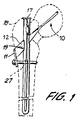
- Fig. 1 is a schematic view showing an osteosynthetic assembly according to the invention, including a fixation plate and an intramedullary nail implanted in a femur;
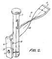
- Fig. 2 is a more detailed, partially fragmentary, schematic view showing the fixation plate of Fig. 1 inserted in an intramedullary nail;
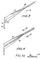
- Fig. 3 is a view in side elevation of the fixation plate of Fig. 1;
- Fig. 4 is a view in side elevation of a modified fixation plate used in the invention;
- Fig. 4A is a cross sectional view, showing the section A-A of Fig. 4;
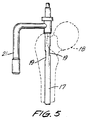
- Fig. 5 is a schematic view showing insertion of an intramedullary nail into a femur in an osteosynthetic procedure using the assembly according to the invention;
- Fig. 6 is a schematic view showing insertion of a guide wire such as a Kirschner wire through the intramedullary nail of Fig. 5;
- Fig. 7 is a schematic view showing use of a chisel in an osteosynthetic procedure to cut a hole in the lateral side of the femur at the correct angle for implantation of an assembly according to the invention; and
- Fig. 8 is a schematic view showing insertion of the fixation plate of an assembly according to the invention into the fractured femur.
- The osteosynthetic assembly according to the invention is shown in Figs. 1 and 2. As shown in Figure 1, an
intramedullary nail 17 is positioned in the medulla of afemur 18. Theintramedullary nail 17 may be of any suitable design and material, although it is preferred to use anintramedullary nail 17 of the type shown and described in the US-Patent No. 4,628,920. Theintramedullary nail 17 is provided with aslot 19 to accommodate theblade 12 of afixation plate 10 and one or more throughholes 26 to accommodate one or more retainingscrews 27 inserted throughscrew hole 14 in theretaining plate 11. Additional screw holes (not shown) may be provided to permit transverse retaining screws or bolts (not shown) to be inserted at the distal end of theintramedullary nail 17. - Referring now to Fig. 3, the
fixation plate 10 as used in the assembly according to the invention comprises aretaining plate 11 which is adapted to lie along the lateral shaft of thefemur 18 and ablade 12 which extends transversely to the plane ofretaining plate 11. Theaxis 13 of theblade 12 forms an angle a with the plane of retainingplate 11 which may vary according to the individual patient, but which will in general be between about 90° and about 150°.
As shown in Fig. 3, theblade 12 is helically twisted around itsaxis 13, the total angular displacement being about 90°.
The retainingplate 11 may be furnished with one or more screw holes 14 for fixing the retainingplate 11 to the lateral shaft of thefemur 18.
A modified version of thefixation plate 10 is shown in Figs. 4 and 4A. Referring to these figures, theblade 15 of thefixation plate 10 may be provided with acannula 16 for receiving a Kirschner guide wire or the like to facilitate insertion of theblade 15 into the bone, in the manner described below. - The method of using an osteosynthetic assembly according to the invention is illustrated in Figs. 5 to 8.
In Fig. 5, anintramedullary nail 17 having the structure shown in Figs. 1 and 2 has been inserted into the lateral shaft of afemur 18, in conventional manner. Attached to theintramedullary nail 17 is aninsertion handle 21, a standard fixture used to insert intramedullary nails. Following emplacement of theintramedullary nail 17, as shown in Fig. 6, aKirschner guide wire 22 may be inserted through the area of the fracture in the neck of thefemur 18, passing throughslot 19 in theintramedullary nail 17. TheKirschner guide wire 22 may be installed in a conventional manner using analignment device 23, attached to the insertion handle 21 to ensure that it is placed at the proper angle. TheKirschner guide wire 22 extends from the exterior of thefemur 18 through the bone across the fracture or fractures. - As shown in Figure 7 the
Kirschner guide wire 22 may then be used to guide the insertion of achisel 24 into thebone 18 at the correct angle to cut a hole in the lateral side of thefemur 18. Thechisel 24 may be cannulated, as at 25, to ensure alignment with theKirschner guide wire 22. - Figure 8 shows the
fixation plate 10 used in the assembly according to the invention about to be inserted into the fracturedfemur 18. If theblade 15 is cannulated, as shown in Figs. 4 and 4A, thecannula 16 of thefixation plate 10 is slid over theKirschner guide wire 22 to ensure insertion of thefixation plate 10 at the correct angle. It is not necessary, however, to have such acannula 16 on theblade 15 of thefixation plate 10. - Referring back to Fig. 1, the
fixation plate 10 has been inserted and the outer retainingplate 11 lies against the exterior of the lateral shaft of thefemur 18. Ascrew 27 is inserted through thescrew hole 14 in the retainingplate 11, into the bone and throughscrew hole 26 in theintramedullary nail 17.
Referring to Fig. 2, when theblade 12 is inserted in theintramedullary nail 17 through itsslot 19 its major dimension, W, transverse to itsaxis 13, of the portion of theblade 12 in and near theslot 19 is parallel to the axis of thefemur 18 into which theintramedullary nail 17 is inserted. Thus the major bending stress, which will occur at the end of theblade 12 nearest the retainingplate 11, will be borne by the major dimension of theblade 12. On the other hand, at the outer end of theblade 12, its major dimension, W, will be transverse to the axis of theintramedullary nail 17 and to the axis of thefemur 18 in which it is inserted. Thus theblade 12 will give maximum support where it is actually needed.
Theblade 12 of thefixation plate 10 has a large surface area, yet thefixation plate 10 of the assembly according to the invention is less bulky than prior art devices. Consequently it is able to support even soft bone structure.
Claims (7)
- An assembly for use in osteosynthesis, said assembly comprising an intramedullary nail (17) for insertion into the medulla of a femur (18) and a fixation device (10) with a helically twisted blade (12) for insertion into the head of the femur (18), and said nail (17) having a through hole (19) to receive and support the blade (12) of said fixation device (10),
characterized in thatA) said fixation device (10) has a retaining plate (11) for positioning along the outside surface of the shank of the femur (18);B) said helically twisted blade (12) extends from said plate (11);C) said through hole (19) permits movement of said blade (12) relative to said nail (17), said nail (17) and the retaining plate (11) of said fixation device (10) having cooperative apertures (14,26) for receiving retaining means (27) extending through the aperture (14) of said plate (11), through the bone (18) and into the aperture (26) of said nail (17); andD) said fixation device (10) is movably supported by the bottom wall of said through hole (19) of said intramedullary nail (17) allowing the angular and/or longitudinal positioning of said helically twisted blade (12) by the action of said retaining means (27) for retaining firmly said fixation device (10) to said intramedullary nail (17). - An assembly according to claim 1, characterized in that the blade (12) is helically twisted around its axis (13), preferably in a continuous way, the total angular displacement being about 90°.
- An assembly according to claim 1 or 2, characterized in that the blade (12) has a longitudinal axis (13) which forms an angle a in the range of 90 - 150° with the plane of said retaining plate (11).
- An assembly according to one of the claims 1 to 3, characterized in that the blade (15) has a cannula (16) for receiving a guide wire (22).
- An assembly according to one of the claims 1 to 4, characterized in that the portion of the blade (12;15) nearest to the retaining plate (11) is orthogonal to said retaining plate (11).
- An assembly according to one of the claims 1 to 5, characterized in that when said blade (12;15) is positioned in the through hole (19) of said intramedullary nail (17) the portion of the blade (12,15) in the through hole (19) has its major dimension generally parallel to the longitudinal axis of said intramedullary nail (17), and the portion of the blade (12,15) most remote from said retaining plate (11) has its major dimension generally transverse to the longitudinal axis of said intramedullary nail (17).
- An assembly according to one of the claims 1 to 6, characterized in that said means (27) are in form of retaining screws (27) inserted through the said cooperative apertures (14) of said retaining plate (11).
Applications Claiming Priority (2)
| Application Number | Priority Date | Filing Date | Title |
|---|---|---|---|
| US388848 | 1989-08-03 | ||
| US07/388,848 US4978349A (en) | 1989-08-03 | 1989-08-03 | Fixation plate |
Publications (2)
| Publication Number | Publication Date |
|---|---|
| EP0411273A1 EP0411273A1 (en) | 1991-02-06 |
| EP0411273B1 true EP0411273B1 (en) | 1995-10-11 |
Family
ID=23535782
Family Applications (1)
| Application Number | Title | Priority Date | Filing Date |
|---|---|---|---|
| EP90110558A Expired - Lifetime EP0411273B1 (en) | 1989-08-03 | 1990-06-05 | Osteosynthetic assembly with twist fixation plate |
Country Status (4)
| Country | Link |
|---|---|
| US (1) | US4978349A (en) |
| EP (1) | EP0411273B1 (en) |
| CA (1) | CA2011751C (en) |
| DE (1) | DE69022915T2 (en) |
Families Citing this family (136)
| Publication number | Priority date | Publication date | Assignee | Title |
|---|---|---|---|---|
| CH682300A5 (en) * | 1990-12-17 | 1993-08-31 | Synthes Ag | |
| DE9115201U1 (en) * | 1991-12-07 | 1992-02-06 | Howmedica GmbH, 2314 Schönkirchen | Bone nail for the treatment of radius fractures |
| US5443466A (en) * | 1991-12-13 | 1995-08-22 | Shah; Mrugesh K. | Method and apparatus for treating fractures of a bone |
| DE4318150C2 (en) * | 1993-06-01 | 1996-08-01 | Endocare Ag | Osteosynthesis tools for the treatment of subtrochanteric and pertrochanteric fractures as well as fractures of the femoral neck |
| US8070786B2 (en) * | 1993-01-21 | 2011-12-06 | Acumed Llc | System for fusing joints |
| US9161793B2 (en) | 1993-01-21 | 2015-10-20 | Acumed Llc | Axial tension screw |
| ES2188765T3 (en) | 1996-07-31 | 2003-07-01 | Synthes Ag | FRACTURED HIP ARTICULATION HEAD FIXING DEVICE. |
| US6648890B2 (en) | 1996-11-12 | 2003-11-18 | Triage Medical, Inc. | Bone fixation system with radially extendable anchor |
| US20050143734A1 (en) * | 1996-11-12 | 2005-06-30 | Cachia Victor V. | Bone fixation system with radially extendable anchor |
| US6632224B2 (en) | 1996-11-12 | 2003-10-14 | Triage Medical, Inc. | Bone fixation system |
| ATE224675T1 (en) | 1996-12-02 | 2002-10-15 | Synthes Ag | FLAT INTEGRAL NAIL |
| US5741256A (en) | 1997-01-13 | 1998-04-21 | Synthes (U.S.A.) | Helical osteosynthetic implant |
| US6123709A (en) * | 1997-07-25 | 2000-09-26 | Jones; Andrew R. | Bone buttress plate and method of using same |
| ATE255856T1 (en) | 1998-03-05 | 2003-12-15 | Synthes Ag | INTRADURAL NAIL WITH LOCKING HOLE |
| DE29804268U1 (en) * | 1998-03-11 | 1998-05-14 | Synthes AG Chur, Chur, Graubünden | Spiral blade insertion instrument |
| US6120504A (en) * | 1998-12-10 | 2000-09-19 | Biomet Inc. | Intramedullary nail having dual distal bore formation |
| US6110175A (en) * | 1999-01-20 | 2000-08-29 | Synthes (Usa) | Surgical chisel and method of using same |
| US6221074B1 (en) | 1999-06-10 | 2001-04-24 | Orthodyne, Inc. | Femoral intramedullary rod system |
| US7018380B2 (en) * | 1999-06-10 | 2006-03-28 | Cole J Dean | Femoral intramedullary rod system |
| US6926719B2 (en) | 1999-10-21 | 2005-08-09 | Gary W. Sohngen | Modular intramedullary nail |
| WO2001034045A1 (en) | 1999-11-11 | 2001-05-17 | Synthes Ag Chur | Radially expandable intramedullary nail |
| US6409730B1 (en) | 2000-05-31 | 2002-06-25 | Synthes (Usa) | Humeral spiral blade |
| TR200402686T4 (en) * | 2000-12-08 | 2004-11-22 | Synthes Ag Chur | Means for fixing the bones, in particular the spine parts, relative to each other |
| US6702817B2 (en) * | 2001-01-19 | 2004-03-09 | Aesculap Ag & Co. Kg | Locking mechanism for a bone screw |
| US6511481B2 (en) | 2001-03-30 | 2003-01-28 | Triage Medical, Inc. | Method and apparatus for fixation of proximal femoral fractures |
| US6887243B2 (en) | 2001-03-30 | 2005-05-03 | Triage Medical, Inc. | Method and apparatus for bone fixation with secondary compression |
| US6835197B2 (en) | 2001-10-17 | 2004-12-28 | Christoph Andreas Roth | Bone fixation system |
| US6572620B1 (en) * | 2001-11-16 | 2003-06-03 | Lew C. Schon | Modular, blade-rod, intramedullary fixation device |
| US6685706B2 (en) * | 2001-11-19 | 2004-02-03 | Triage Medical, Inc. | Proximal anchors for bone fixation system |
| KR100485896B1 (en) * | 2002-01-17 | 2005-04-29 | 조우신 | Device for inserting screws into an intramedullary nail and method thereof |
| US6793678B2 (en) | 2002-06-27 | 2004-09-21 | Depuy Acromed, Inc. | Prosthetic intervertebral motion disc having dampening |
| FR2841460B1 (en) * | 2002-06-28 | 2005-04-01 | Sanortho | EPIPHYSARY OSTEOSYNTHESIS SCREW IN TWO PARTS, IN PARTICULAR FOR NAILS OR PLATES, AND OSTEOSYNTHESIS DEVICE INCORPORATING IT |
| WO2004008949A2 (en) | 2002-07-19 | 2004-01-29 | Triage Medical, Inc. | Method and apparatus for spinal fixation |
| AU2002328245A1 (en) * | 2002-10-03 | 2004-04-23 | Synthes Ag Chur | Device for bone fixation |
| US7070601B2 (en) | 2003-01-16 | 2006-07-04 | Triage Medical, Inc. | Locking plate for bone anchors |
| JP4579697B2 (en) | 2003-03-07 | 2010-11-10 | ジンテーズ ゲゼルシャフト ミト ベシュレンクテル ハフツング | Set screw for intramedullary nail |
| WO2004098453A2 (en) | 2003-05-06 | 2004-11-18 | Triage Medical, Inc. | Proximal anchors for bone fixation system |
| DE50308380D1 (en) | 2003-06-12 | 2007-11-22 | Synthes Gmbh | SURGICAL NAIL |
| NZ543998A (en) | 2003-06-12 | 2007-11-30 | Synthes Gmbh | Surgical nail |
| NZ544958A (en) | 2003-07-30 | 2009-01-31 | Synthes Gmbh | Surgical nail |
| US7635365B2 (en) | 2003-08-28 | 2009-12-22 | Ellis Thomas J | Bone plates |
| JP4695511B2 (en) * | 2003-08-29 | 2011-06-08 | ジンテーズ ゲゼルシャフト ミト ベシュレンクテル ハフツング | Intramedullary nail |
| US7780667B2 (en) | 2003-09-08 | 2010-08-24 | Smith & Nephew, Inc. | Orthopaedic plate and screw assembly |
| US20050055024A1 (en) | 2003-09-08 | 2005-03-10 | James Anthony H. | Orthopaedic implant and screw assembly |
| US7799030B2 (en) | 2003-09-08 | 2010-09-21 | Smith & Nephew, Inc. | Orthopaedic plate and screw assembly |
| US8105367B2 (en) | 2003-09-29 | 2012-01-31 | Smith & Nephew, Inc. | Bone plate and bone plate assemblies including polyaxial fasteners |
| WO2007014192A2 (en) | 2005-07-25 | 2007-02-01 | Smith & Nephew, Inc. | Systems and methods for using polyaxial plates |
| US8070750B2 (en) | 2004-03-05 | 2011-12-06 | Depuy Mitek, Inc. | Tunnel notcher and guidewire delivery device |
| US8092454B2 (en) * | 2004-03-11 | 2012-01-10 | Sohngen Gary W | Fixation instrument for treating a bone fracture |
| ATE426366T1 (en) | 2004-06-22 | 2009-04-15 | Synthes Gmbh | INTRAMEDULLAR INTRAMEDULLAR NAIL |
| CA2571508C (en) | 2004-06-30 | 2012-03-13 | Synthes (U.S.A.) | Surgical nail |
| US7232442B2 (en) * | 2005-02-22 | 2007-06-19 | Advanced Orthopaedic Solutions | Humeral nail |
| US9060820B2 (en) | 2005-05-18 | 2015-06-23 | Sonoma Orthopedic Products, Inc. | Segmented intramedullary fracture fixation devices and methods |
| US7846162B2 (en) | 2005-05-18 | 2010-12-07 | Sonoma Orthopedic Products, Inc. | Minimally invasive actuable bone fixation devices |
| US8961516B2 (en) | 2005-05-18 | 2015-02-24 | Sonoma Orthopedic Products, Inc. | Straight intramedullary fracture fixation devices and methods |
| US20060293667A1 (en) * | 2005-05-19 | 2006-12-28 | Agnes Vignery | Bone implant device and methods of using same |
| US8382807B2 (en) | 2005-07-25 | 2013-02-26 | Smith & Nephew, Inc. | Systems and methods for using polyaxial plates |
| WO2007019710A1 (en) * | 2005-08-15 | 2007-02-22 | Synthes Gmbh | Osteosynthetic device |
| US7967820B2 (en) * | 2006-02-07 | 2011-06-28 | P Tech, Llc. | Methods and devices for trauma welding |
| US8211107B2 (en) * | 2006-05-10 | 2012-07-03 | Concepts In Medicine, Llc | Modular, blade-rod, intramedullary fixation device |
| US10687869B2 (en) * | 2006-07-05 | 2020-06-23 | Advanced Orthopaedic Solutions, Inc. | Trochanteric nail with locking opening |
| CA2670263A1 (en) | 2006-11-22 | 2008-05-29 | Sonoma Orthopedic Products, Inc. | Fracture fixation device, tools and methods |
| US8105382B2 (en) | 2006-12-07 | 2012-01-31 | Interventional Spine, Inc. | Intervertebral implant |
| US8579985B2 (en) | 2006-12-07 | 2013-11-12 | Ihip Surgical, Llc | Method and apparatus for hip replacement |
| US8974540B2 (en) | 2006-12-07 | 2015-03-10 | Ihip Surgical, Llc | Method and apparatus for attachment in a modular hip replacement or fracture fixation device |
| WO2008069800A1 (en) | 2006-12-07 | 2008-06-12 | Anatol Podolsky | Method and apparatus for total hip replacement |
| US7918853B2 (en) * | 2007-03-20 | 2011-04-05 | Smith & Nephew, Inc. | Orthopaedic plate and screw assembly |
| CZ300464B6 (en) * | 2007-04-02 | 2009-05-27 | Pompach@Martin | Means for calcaneum osteosynthesis |
| US7998176B2 (en) | 2007-06-08 | 2011-08-16 | Interventional Spine, Inc. | Method and apparatus for spinal stabilization |
| US8900307B2 (en) | 2007-06-26 | 2014-12-02 | DePuy Synthes Products, LLC | Highly lordosed fusion cage |
| CN103271761B (en) | 2008-01-14 | 2015-10-28 | 康文图斯整形外科公司 | For the apparatus and method of fracture repair |
| AU2009205896A1 (en) | 2008-01-17 | 2009-07-23 | Synthes Gmbh | An expandable intervertebral implant and associated method of manufacturing the same |
| GB2460909B (en) * | 2008-01-28 | 2010-09-08 | Mark B Sommers | Bone Nail |
| US8114079B2 (en) * | 2008-03-31 | 2012-02-14 | Depuy Products, Inc. | Intramedullary nail with coupled shafts |
| BRPI0910325A8 (en) | 2008-04-05 | 2019-01-29 | Synthes Gmbh | expandable intervertebral implant |
| EP2299917A1 (en) | 2008-06-10 | 2011-03-30 | Sonoma Orthopedic Products, Inc. | Fracture fixation device, tools and methods |
| AU2009296243A1 (en) | 2008-09-26 | 2010-04-01 | Sonoma Orthopedic Products, Inc. | Bone fixation device, tools and methods |
| US9237910B2 (en) | 2012-01-26 | 2016-01-19 | Acute Innovations Llc | Clip for rib stabilization |
| US12285197B2 (en) | 2008-10-10 | 2025-04-29 | Acumed Llc | Bone fixation system with opposed mounting portions |
| US8668695B2 (en) * | 2008-10-15 | 2014-03-11 | Zimmer Gmbh | Intramedullary nail |
| US9526620B2 (en) | 2009-03-30 | 2016-12-27 | DePuy Synthes Products, Inc. | Zero profile spinal fusion cage |
| US8419735B2 (en) * | 2009-05-05 | 2013-04-16 | Synthes Usa, Llc | Nail locking systems |
| US8449544B2 (en) * | 2009-06-30 | 2013-05-28 | Smith & Nephew, Inc. | Orthopaedic implant and fastener assembly |
| CN102639074B (en) | 2009-06-30 | 2016-03-16 | 史密夫和内修有限公司 | Orthopedic implants and fastening components |
| EP3130299A1 (en) | 2009-11-09 | 2017-02-15 | Spinewelding AG | Medical device and aparatus |
| US9393129B2 (en) | 2009-12-10 | 2016-07-19 | DePuy Synthes Products, Inc. | Bellows-like expandable interbody fusion cage |
| US8568417B2 (en) | 2009-12-18 | 2013-10-29 | Charles River Engineering Solutions And Technologies, Llc | Articulating tool and methods of using |
| WO2011088172A1 (en) | 2010-01-15 | 2011-07-21 | Brenzel Michael P | Rotary-rigid orthopaedic rod |
| EP2523616B1 (en) | 2010-01-20 | 2019-04-17 | Conventus Orthopaedics, Inc. | Apparatus for bone access and cavity preparation |
| JP2013521880A (en) | 2010-03-08 | 2013-06-13 | コンベンタス オーソピディックス, インコーポレイテッド | Apparatus and method for securing a bone implant |
| EP2544609A4 (en) * | 2010-03-08 | 2017-05-31 | Conventus Orthopaedics, Inc. | Apparatus and methods for bone repair |
| US8979860B2 (en) | 2010-06-24 | 2015-03-17 | DePuy Synthes Products. LLC | Enhanced cage insertion device |
| US9763678B2 (en) | 2010-06-24 | 2017-09-19 | DePuy Synthes Products, Inc. | Multi-segment lateral cage adapted to flex substantially in the coronal plane |
| AU2011271465B2 (en) | 2010-06-29 | 2015-03-19 | Synthes Gmbh | Distractible intervertebral implant |
| US9131973B2 (en) * | 2010-07-09 | 2015-09-15 | Medartis Ag | Osteosynthesis system |
| US9402732B2 (en) | 2010-10-11 | 2016-08-02 | DePuy Synthes Products, Inc. | Expandable interspinous process spacer implant |
| RU2013158111A (en) | 2011-06-15 | 2015-07-20 | Смит Энд Нефью, Инк. | IMPLANT WITH A VARIABLE ANGLE OF FIXATION |
| JP6240076B2 (en) | 2011-09-30 | 2017-11-29 | アキュート・イノヴェーションズ・エルエルシー | Bone fixation system with opposing mounting parts |
| EP2671542A1 (en) * | 2012-06-06 | 2013-12-11 | Universitätsspital Basel | Bone plate for the greater trochanter |
| WO2014018098A1 (en) | 2012-07-26 | 2014-01-30 | DePuy Synthes Products, LLC | Expandable implant |
| US20140067069A1 (en) | 2012-08-30 | 2014-03-06 | Interventional Spine, Inc. | Artificial disc |
| US9717601B2 (en) | 2013-02-28 | 2017-08-01 | DePuy Synthes Products, Inc. | Expandable intervertebral implant, system, kit and method |
| US9522070B2 (en) | 2013-03-07 | 2016-12-20 | Interventional Spine, Inc. | Intervertebral implant |
| US9522028B2 (en) | 2013-07-03 | 2016-12-20 | Interventional Spine, Inc. | Method and apparatus for sacroiliac joint fixation |
| WO2015052841A1 (en) * | 2013-10-11 | 2015-04-16 | プロスパー株式会社 | Device for osteosynthesis and osteosynthesis |
| JP6539652B2 (en) | 2013-12-12 | 2019-07-03 | コンベンタス オーソピディックス, インコーポレイテッド | Tissue displacement tools and methods |
| US9770278B2 (en) | 2014-01-17 | 2017-09-26 | Arthrex, Inc. | Dual tip guide wire |
| US10045803B2 (en) | 2014-07-03 | 2018-08-14 | Mayo Foundation For Medical Education And Research | Sacroiliac joint fusion screw and method |
| US9814499B2 (en) | 2014-09-30 | 2017-11-14 | Arthrex, Inc. | Intramedullary fracture fixation devices and methods |
| US11426290B2 (en) | 2015-03-06 | 2022-08-30 | DePuy Synthes Products, Inc. | Expandable intervertebral implant, system, kit and method |
| US10117687B2 (en) * | 2015-03-25 | 2018-11-06 | Pier Giovanni Menci | Intramedullary nail for the treatment of fractures of the long bones |
| US9913727B2 (en) | 2015-07-02 | 2018-03-13 | Medos International Sarl | Expandable implant |
| US10993750B2 (en) | 2015-09-18 | 2021-05-04 | Smith & Nephew, Inc. | Bone plate |
| US10751071B2 (en) | 2016-04-25 | 2020-08-25 | Imds Llc | Joint fusion instrumentation and methods |
| US10413332B2 (en) | 2016-04-25 | 2019-09-17 | Imds Llc | Joint fusion implant and methods |
| CN109640889B (en) | 2016-06-28 | 2021-07-30 | Eit 新兴移植技术股份有限公司 | Expandable Angle Adjustable Articulation Intervertebral Cage |
| JP6995789B2 (en) | 2016-06-28 | 2022-01-17 | イーアイティー・エマージング・インプラント・テクノロジーズ・ゲーエムベーハー | Expandable and angle adjustable intervertebral cage |
| US11083503B2 (en) | 2016-09-22 | 2021-08-10 | Globus Medical, Inc. | Systems and methods for intramedullary nail implantation |
| US10299847B2 (en) * | 2016-09-22 | 2019-05-28 | Globus Medical, Inc. | Systems and methods for intramedullary nail implantation |
| US10492803B2 (en) | 2016-09-22 | 2019-12-03 | Globus Medical, Inc. | Systems and methods for intramedullary nail implantation |
| US10537436B2 (en) | 2016-11-01 | 2020-01-21 | DePuy Synthes Products, Inc. | Curved expandable cage |
| US10888433B2 (en) | 2016-12-14 | 2021-01-12 | DePuy Synthes Products, Inc. | Intervertebral implant inserter and related methods |
| US10631881B2 (en) | 2017-03-09 | 2020-04-28 | Flower Orthopedics Corporation | Plating depth gauge and countersink instrument |
| US10398563B2 (en) | 2017-05-08 | 2019-09-03 | Medos International Sarl | Expandable cage |
| US11344424B2 (en) | 2017-06-14 | 2022-05-31 | Medos International Sarl | Expandable intervertebral implant and related methods |
| WO2019010252A2 (en) | 2017-07-04 | 2019-01-10 | Conventus Orthopaedics, Inc. | APPARATUS AND METHODS FOR TREATING BONES |
| US10940016B2 (en) | 2017-07-05 | 2021-03-09 | Medos International Sarl | Expandable intervertebral fusion cage |
| US11446156B2 (en) | 2018-10-25 | 2022-09-20 | Medos International Sarl | Expandable intervertebral implant, inserter instrument, and related methods |
| US11633219B2 (en) | 2019-06-26 | 2023-04-25 | Globus Medical, Inc. | Fenestrated pedicle nail |
| US11426286B2 (en) | 2020-03-06 | 2022-08-30 | Eit Emerging Implant Technologies Gmbh | Expandable intervertebral implant |
| US11850160B2 (en) | 2021-03-26 | 2023-12-26 | Medos International Sarl | Expandable lordotic intervertebral fusion cage |
| US11752009B2 (en) | 2021-04-06 | 2023-09-12 | Medos International Sarl | Expandable intervertebral fusion cage |
| US12035928B2 (en) * | 2021-11-12 | 2024-07-16 | NextWave Medical, LLC | Devices and methods for correction of hip deformities |
| CN114145830A (en) * | 2021-12-09 | 2022-03-08 | 陈聚伍 | Femoral neck fracture fixing device |
| US12090064B2 (en) | 2022-03-01 | 2024-09-17 | Medos International Sarl | Stabilization members for expandable intervertebral implants, and related systems and methods |
| EP4268742A1 (en) * | 2022-04-26 | 2023-11-01 | Stryker European Operations Limited | Internal brace plate |
Citations (1)
| Publication number | Priority date | Publication date | Assignee | Title |
|---|---|---|---|---|
| US3025853A (en) * | 1958-07-07 | 1962-03-20 | Christopher A Mason | Fixation device for fractured femur |
Family Cites Families (8)
| Publication number | Priority date | Publication date | Assignee | Title |
|---|---|---|---|---|
| US4103683A (en) * | 1977-06-03 | 1978-08-01 | Neufeld John A | Sub-trochanteric nail |
| US4341206A (en) * | 1978-12-19 | 1982-07-27 | Synthes Ag | Device for producing a hole in a bone |
| EP0145666B1 (en) * | 1983-12-12 | 1988-06-22 | Synthes Ag Chur | Intramedullary nail |
| US4697585A (en) * | 1985-01-11 | 1987-10-06 | Williams Michael O | Appliance for fixing fractures of the femur |
| RO89820B1 (en) * | 1985-11-05 | 2002-06-28 | îNTREPRINDEREA INDUSTRIA TEHNICO MEDICALA | Elastic implants for a stable elastic osteorrhaphy of femoral and tibial fractures, respectively, as well as corresponding instrumentation |
| US4733654A (en) * | 1986-05-29 | 1988-03-29 | Marino James F | Intramedullar nailing assembly |
| DE8620399U1 (en) * | 1986-07-30 | 1986-10-09 | Howmedica GmbH Werk Schönkirchen, 2314 Schönkirchen | Osteosynthesis aids for the treatment of subtrochanteric fractures |
| US4827917A (en) * | 1986-12-30 | 1989-05-09 | Richards Medical Company | Fermoral fracture device |
-
1989
- 1989-08-03 US US07/388,848 patent/US4978349A/en not_active Expired - Lifetime
-
1990
- 1990-03-08 CA CA002011751A patent/CA2011751C/en not_active Expired - Lifetime
- 1990-06-05 EP EP90110558A patent/EP0411273B1/en not_active Expired - Lifetime
- 1990-06-05 DE DE69022915T patent/DE69022915T2/en not_active Expired - Lifetime
Patent Citations (1)
| Publication number | Priority date | Publication date | Assignee | Title |
|---|---|---|---|---|
| US3025853A (en) * | 1958-07-07 | 1962-03-20 | Christopher A Mason | Fixation device for fractured femur |
Also Published As
| Publication number | Publication date |
|---|---|
| DE69022915D1 (en) | 1995-11-16 |
| US4978349A (en) | 1990-12-18 |
| EP0411273A1 (en) | 1991-02-06 |
| CA2011751A1 (en) | 1991-02-03 |
| DE69022915T2 (en) | 1996-04-04 |
| CA2011751C (en) | 1996-02-20 |
Similar Documents
| Publication | Publication Date | Title |
|---|---|---|
| EP0411273A1 (en) | Osteosynthetic assembly with twist fixation plate | |
| US5562666A (en) | Method for treating intertrochanteric fracture utilizing a femoral fracture device | |
| KR100904142B1 (en) | Intramedullary fixation assembly and devices and methods for installing the same | |
| US7799030B2 (en) | Orthopaedic plate and screw assembly | |
| US9451971B2 (en) | Intramedullary fixation assembly and devices and methods for installing the same | |
| EP1663038B1 (en) | Orthopaedic plate and bone screw assembly | |
| EP1855605B1 (en) | Nail plate system | |
| US5167663A (en) | Femoral fracture device | |
| EP1507486B1 (en) | Intramedullary fixation device for metaphyseal long bone fractures | |
| US20070299447A1 (en) | Orthopaedic plate and screw assembly | |
| US7686808B2 (en) | Fracture fixation device and implantation jig therefor | |
| US7938850B2 (en) | Nail plate | |
| US20030018336A1 (en) | Intramedullary nail with modular sleeve | |
| WO2007109302A2 (en) | Orthopaedic plate and screw assembly | |
| JP2608667B2 (en) | Locking nails for treatment of trunk-side femoral fractures | |
| US20060161156A1 (en) | Fracture fixation device | |
| US8668693B2 (en) | Fixation device for proximal elbow fractures and method of using same | |
| US20060149257A1 (en) | Fracture fixation device | |
| CA2640225A1 (en) | A fracture fixation device and implantation jig therefor | |
| AU2003234384B2 (en) | Intramedullary fixation device for metaphyseal long bone fractures |
Legal Events
| Date | Code | Title | Description |
|---|---|---|---|
| PUAI | Public reference made under article 153(3) epc to a published international application that has entered the european phase |
Free format text: ORIGINAL CODE: 0009012 |
|
| 17P | Request for examination filed |
Effective date: 19900605 |
|
| AK | Designated contracting states |
Kind code of ref document: A1 Designated state(s): CH DE FR GB LI |
|
| RAP1 | Party data changed (applicant data changed or rights of an application transferred) |
Owner name: SYNTHES AG, CHUR |
|
| 17Q | First examination report despatched |
Effective date: 19930811 |
|
| GRAA | (expected) grant |
Free format text: ORIGINAL CODE: 0009210 |
|
| AK | Designated contracting states |
Kind code of ref document: B1 Designated state(s): CH DE FR GB LI |
|
| ET | Fr: translation filed | ||
| REF | Corresponds to: |
Ref document number: 69022915 Country of ref document: DE Date of ref document: 19951116 |
|
| PLBE | No opposition filed within time limit |
Free format text: ORIGINAL CODE: 0009261 |
|
| STAA | Information on the status of an ep patent application or granted ep patent |
Free format text: STATUS: NO OPPOSITION FILED WITHIN TIME LIMIT |
|
| 26N | No opposition filed | ||
| REG | Reference to a national code |
Ref country code: GB Ref legal event code: IF02 |
|
| REG | Reference to a national code |
Ref country code: CH Ref legal event code: PUE Owner name: SYNTHES GMBH Free format text: SYNTHES AG CHUR#GRABENSTRASSE 15#7000 CHUR (CH) -TRANSFER TO- SYNTHES GMBH#EIMATTSTRASSE 3#4436 OBERDORF (CH) |
|
| REG | Reference to a national code |
Ref country code: GB Ref legal event code: 732E |
|
| REG | Reference to a national code |
Ref country code: FR Ref legal event code: TP |
|
| PGFP | Annual fee paid to national office [announced via postgrant information from national office to epo] |
Ref country code: CH Payment date: 20090615 Year of fee payment: 20 |
|
| PGFP | Annual fee paid to national office [announced via postgrant information from national office to epo] |
Ref country code: DE Payment date: 20090529 Year of fee payment: 20 Ref country code: GB Payment date: 20090603 Year of fee payment: 20 |
|
| REG | Reference to a national code |
Ref country code: CH Ref legal event code: PL |
|
| REG | Reference to a national code |
Ref country code: GB Ref legal event code: PE20 Expiry date: 20100604 |
|
| PG25 | Lapsed in a contracting state [announced via postgrant information from national office to epo] |
Ref country code: GB Free format text: LAPSE BECAUSE OF EXPIRATION OF PROTECTION Effective date: 20100604 |
|
| PG25 | Lapsed in a contracting state [announced via postgrant information from national office to epo] |
Ref country code: DE Free format text: LAPSE BECAUSE OF EXPIRATION OF PROTECTION Effective date: 20100605 |
|
| PGFP | Annual fee paid to national office [announced via postgrant information from national office to epo] |
Ref country code: FR Payment date: 20090611 Year of fee payment: 20 |