EP0410416B1 - Applying a bung seal to an electrical lead - Google Patents
Applying a bung seal to an electrical lead Download PDFInfo
- Publication number
- EP0410416B1 EP0410416B1 EP90114260A EP90114260A EP0410416B1 EP 0410416 B1 EP0410416 B1 EP 0410416B1 EP 90114260 A EP90114260 A EP 90114260A EP 90114260 A EP90114260 A EP 90114260A EP 0410416 B1 EP0410416 B1 EP 0410416B1
- Authority
- EP
- European Patent Office
- Prior art keywords
- seal
- bung
- lead
- receptacle
- jaws
- Prior art date
- Legal status (The legal status is an assumption and is not a legal conclusion. Google has not performed a legal analysis and makes no representation as to the accuracy of the status listed.)
- Expired - Lifetime
Links
- 238000003780 insertion Methods 0.000 claims description 13
- 230000037431 insertion Effects 0.000 claims description 13
- 238000000034 method Methods 0.000 claims description 5
- 210000001331 nose Anatomy 0.000 description 12
- 238000002788 crimping Methods 0.000 description 4
- 238000009413 insulation Methods 0.000 description 3
- 230000008878 coupling Effects 0.000 description 2
- 238000010168 coupling process Methods 0.000 description 2
- 238000005859 coupling reaction Methods 0.000 description 2
- 239000013536 elastomeric material Substances 0.000 description 2
- 238000003491 array Methods 0.000 description 1
- 230000000694 effects Effects 0.000 description 1
- 238000000605 extraction Methods 0.000 description 1
- 230000035515 penetration Effects 0.000 description 1
Images


Classifications
-
- H—ELECTRICITY
- H01—ELECTRIC ELEMENTS
- H01R—ELECTRICALLY-CONDUCTIVE CONNECTIONS; STRUCTURAL ASSOCIATIONS OF A PLURALITY OF MUTUALLY-INSULATED ELECTRICAL CONNECTING ELEMENTS; COUPLING DEVICES; CURRENT COLLECTORS
- H01R43/00—Apparatus or processes specially adapted for manufacturing, assembling, maintaining, or repairing of line connectors or current collectors or for joining electric conductors
- H01R43/005—Apparatus or processes specially adapted for manufacturing, assembling, maintaining, or repairing of line connectors or current collectors or for joining electric conductors for making dustproof, splashproof, drip-proof, waterproof, or flameproof connection, coupling, or casing
-
- H—ELECTRICITY
- H01—ELECTRIC ELEMENTS
- H01R—ELECTRICALLY-CONDUCTIVE CONNECTIONS; STRUCTURAL ASSOCIATIONS OF A PLURALITY OF MUTUALLY-INSULATED ELECTRICAL CONNECTING ELEMENTS; COUPLING DEVICES; CURRENT COLLECTORS
- H01R13/00—Details of coupling devices of the kinds covered by groups H01R12/70 or H01R24/00 - H01R33/00
- H01R13/46—Bases; Cases
- H01R13/52—Dustproof, splashproof, drip-proof, waterproof, or flameproof cases
-
- H—ELECTRICITY
- H01—ELECTRIC ELEMENTS
- H01R—ELECTRICALLY-CONDUCTIVE CONNECTIONS; STRUCTURAL ASSOCIATIONS OF A PLURALITY OF MUTUALLY-INSULATED ELECTRICAL CONNECTING ELEMENTS; COUPLING DEVICES; CURRENT COLLECTORS
- H01R13/00—Details of coupling devices of the kinds covered by groups H01R12/70 or H01R24/00 - H01R33/00
- H01R13/56—Means for preventing chafing or fracture of flexible leads at outlet from coupling part
- H01R13/562—Bending-relieving
-
- H—ELECTRICITY
- H01—ELECTRIC ELEMENTS
- H01R—ELECTRICALLY-CONDUCTIVE CONNECTIONS; STRUCTURAL ASSOCIATIONS OF A PLURALITY OF MUTUALLY-INSULATED ELECTRICAL CONNECTING ELEMENTS; COUPLING DEVICES; CURRENT COLLECTORS
- H01R43/00—Apparatus or processes specially adapted for manufacturing, assembling, maintaining, or repairing of line connectors or current collectors or for joining electric conductors
- H01R43/04—Apparatus or processes specially adapted for manufacturing, assembling, maintaining, or repairing of line connectors or current collectors or for joining electric conductors for forming connections by deformation, e.g. crimping tool
- H01R43/048—Crimping apparatus or processes
-
- Y—GENERAL TAGGING OF NEW TECHNOLOGICAL DEVELOPMENTS; GENERAL TAGGING OF CROSS-SECTIONAL TECHNOLOGIES SPANNING OVER SEVERAL SECTIONS OF THE IPC; TECHNICAL SUBJECTS COVERED BY FORMER USPC CROSS-REFERENCE ART COLLECTIONS [XRACs] AND DIGESTS
- Y10—TECHNICAL SUBJECTS COVERED BY FORMER USPC
- Y10T—TECHNICAL SUBJECTS COVERED BY FORMER US CLASSIFICATION
- Y10T29/00—Metal working
- Y10T29/49—Method of mechanical manufacture
- Y10T29/49826—Assembling or joining
- Y10T29/49863—Assembling or joining with prestressing of part
- Y10T29/4987—Elastic joining of parts
-
- Y—GENERAL TAGGING OF NEW TECHNOLOGICAL DEVELOPMENTS; GENERAL TAGGING OF CROSS-SECTIONAL TECHNOLOGIES SPANNING OVER SEVERAL SECTIONS OF THE IPC; TECHNICAL SUBJECTS COVERED BY FORMER USPC CROSS-REFERENCE ART COLLECTIONS [XRACs] AND DIGESTS
- Y10—TECHNICAL SUBJECTS COVERED BY FORMER USPC
- Y10T—TECHNICAL SUBJECTS COVERED BY FORMER US CLASSIFICATION
- Y10T29/00—Metal working
- Y10T29/53—Means to assemble or disassemble
- Y10T29/53039—Means to assemble or disassemble with control means energized in response to activator stimulated by condition sensor
- Y10T29/53061—Responsive to work or work-related machine element
- Y10T29/53074—Responsive to work or work-related machine element with means to fasten by elastic joining
-
- Y—GENERAL TAGGING OF NEW TECHNOLOGICAL DEVELOPMENTS; GENERAL TAGGING OF CROSS-SECTIONAL TECHNOLOGIES SPANNING OVER SEVERAL SECTIONS OF THE IPC; TECHNICAL SUBJECTS COVERED BY FORMER USPC CROSS-REFERENCE ART COLLECTIONS [XRACs] AND DIGESTS
- Y10—TECHNICAL SUBJECTS COVERED BY FORMER USPC
- Y10T—TECHNICAL SUBJECTS COVERED BY FORMER US CLASSIFICATION
- Y10T29/00—Metal working
- Y10T29/53—Means to assemble or disassemble
- Y10T29/5313—Means to assemble electrical device
- Y10T29/532—Conductor
- Y10T29/53209—Terminal or connector
- Y10T29/53213—Assembled to wire-type conductor
- Y10T29/53239—Means to fasten by elastic joining
-
- Y—GENERAL TAGGING OF NEW TECHNOLOGICAL DEVELOPMENTS; GENERAL TAGGING OF CROSS-SECTIONAL TECHNOLOGIES SPANNING OVER SEVERAL SECTIONS OF THE IPC; TECHNICAL SUBJECTS COVERED BY FORMER USPC CROSS-REFERENCE ART COLLECTIONS [XRACs] AND DIGESTS
- Y10—TECHNICAL SUBJECTS COVERED BY FORMER USPC
- Y10T—TECHNICAL SUBJECTS COVERED BY FORMER US CLASSIFICATION
- Y10T29/00—Metal working
- Y10T29/53—Means to assemble or disassemble
- Y10T29/53478—Means to assemble or disassemble with magazine supply
-
- Y—GENERAL TAGGING OF NEW TECHNOLOGICAL DEVELOPMENTS; GENERAL TAGGING OF CROSS-SECTIONAL TECHNOLOGIES SPANNING OVER SEVERAL SECTIONS OF THE IPC; TECHNICAL SUBJECTS COVERED BY FORMER USPC CROSS-REFERENCE ART COLLECTIONS [XRACs] AND DIGESTS
- Y10—TECHNICAL SUBJECTS COVERED BY FORMER USPC
- Y10T—TECHNICAL SUBJECTS COVERED BY FORMER US CLASSIFICATION
- Y10T29/00—Metal working
- Y10T29/53—Means to assemble or disassemble
- Y10T29/53657—Means to assemble or disassemble to apply or remove a resilient article [e.g., tube, sleeve, etc.]
Definitions
- This invention relates to apparatus for, and a method of, applying a hollow bung seal to an electrical lead.
- apparatus for applying a hollow bung seal to an electrical lead comprising; a bung seal source; a bung seal receptacle for receiving a leading bung seal from the bung seal source; a bung seal transfer device comprising a guide structure supporting, for axial movement relative thereto, a bung seal expansion sleeve and a bung seal expansion pin within said sleeve; means for inserting an electrical lead into the sleeve; and drive means for sequentially causing; the expansion pin to enter and expand a bung seal in the bung seal receptacle; the sleeve to enter and further expand the bung seal; the expansion pin to be withdrawn from the bung seal leaving it secured to the sleeve by its own resilience and permitting a lead to be inserted into the sleeve by the lead insertion means; and the sleeve to be withdrawn from the bung seal leaving it secured to the lead by its own resilience.
- the bung seal transfer device is mounted on a turntable and is swung between a position opposite to a bung seal receptacle previously driven through a reciprocating movement to pick up the leading bung seal from the bung seal source, the bung seal transfer device with the bung seal on the expansion sleeve thereof then being swung by the turntable to a position opposite to the lead insertion means which is displaced by some ninety degrees about the axis of rotation of the turntable, from the bung seal receptacle.
- the present invention is intended to provide a straight action apparatus of the above kind in which the turntable is accordingly eliminated.
- apparatus as defined above for applying a hollow bung seal to an electrical lead, is characterized in that the guide structure, the seal receptacle and the bung seal source are mounted in mutually fixed relationship, a bung seal transfer clamp being provided for withdrawing the leading bung seal from the bung seal source and placing it between the bung seal receptacle and the expansion pin, for transfer thereby into the bung seal receptacle, the lead insertion means being mounted for movement towards and away from the side of bung seal receptacle remote from the support structure.
- the apparatus is especially intended for use as part of a harness making assembly comprising a lead making machine for supplying leads to the lead insertion means and for removing the leads with the seals thereon from the lead insertion means and transporting them to a crimping station at which electrical terminals are crimped thereto.
- the bung seal source may have a bung seal outlet which is positioned proximate to the guide structure and the seal receptacle, seal gripping jaws of the seal clamp being moveable rectilinearly, between the guide structure and the seal receptacle, between a first position to close about the leading seal at the seal outlet and a second position to align the leading seal with the expansion pin and the seal receptacle.
- the bung seal source may comprise a magazine containing a column of bung seals, an end portion of the leading seal of the column being supported by a resiliently mounted escapement plate, the jaws of the seal clamp serving to grip the leading seal at a position back from said end portion in the first position of the seal clamp and to remove the leading seal from the magazine, against the resilient action of the escapement plate as the seal clamp is moved towards its second position.
- the seal receptacle may contain a grommet through which the leading end of the expansion pin, and the lead can be passed, and which serves as an abutment against which the leading end of the seal is forced by the expansion pin, as it transfers the seal from the bung seal clamp into the bung seal receptacle.
- the seal receptacle In order to facilitate entry of the seal into the seal receptacle, it may be provided with an enlarged mouth and spring loaded detent means for preventing the seal from backing out from the seal receptacle as the sleeve is withdrawn from the bung seal.
- the support structure comprises a support sleeve fixed to a cylinder block on a base plate of the apparatus, in which sleeve the expansion sleeve and the expansion pin are slideably mounted, the expansion pin being driven by a first piston and cylinder unit fixed to the cylinder block in axial alignment with the support sleeve and the expansion sleeve being driven by a second piston and cylinder unit fixed in said block parallel with the first piston and cylinder unit.
- the second piston and cylinder unit may have its piston rod connected to a lug received in a notch in the expansion sleeve and which is moveable along an axial slot in the support sleeve.
- the lead insertion means may comprise a lead clamp having lead gripping jaws and lead centering jaws, and a drive unit for moving the lead clamp towards and away from the bung seal receptacle, the centering jaws being movable towards the gripping jaws against the action of resilient means, for the purpose of advancing the lead into the bung seal receptacle upon the lead clamp being urged thereagainst by its drive unit.
- the lead clamp were to be advanced towards the seal receptacle with the lead projecting by said sufficient extent, the lead would tend to droop in front of the lead clamp so as to inhibit its insertion into the lead receptacle.
- a method of applying a hollow bung seal to an electrical lead comprises the steps of placing the bung seal in a bung seal receptacle; expanding the bung seal by inserting a first bung seal expansion member therethrough; further expanding the bung seal by inserting a second bung seal expansion member surrounding the first expansion member, between the first expansion member and the seal; withdrawing the first expansion member, leaving the seal secured by its own resilience to the second expansion member; inserting the lead into the second expansion member; and withdrawing the second expansion member, leaving the seal secured about the lead by its own resilience and removing the lead with the bung seal thereon, from the bung seal receptacle; characterized in that the seal is placed in the bung seal receptacle and the lead is inserted thereinto with the bung seal receptacle, the first and second expansion members, and the lead all in axial alignment.
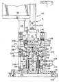
- the main working parts of the apparatus for applying a hollow bung seal to an electrical lead will now be described in outline with reference to Figure 1.
- These main parts comprise a clamp 2 for an electrical lead L, a fixed bung seal magazine 4, a fixed bung seal receptacle 6, a bung seal transfer clamp 8, and a bung seal transfer device 10.
- the device 10 comprises a support structure in the form of a fixed outer sleeve 12, slideably supporting therein a bung seal expansion, inner sleeve 14 having a reduced cross-section, tapered nose 16, and which, in turn, slideably receives a bung seal expansion pin 18 having a tapered bung seal expansion nose 20 formed with a reduced cross-section guide end portion 21.
- the sleeve 14 is arranged to be driven axially relative to the sleeve 12 by the piston rod 24 of a pneumatic piston and cylinder unit 22, a lug 26 on the rod 24 engaging in a notch 28 in the sleeve 14 and in a longitudinal slot 29 in the outer sleeve 12.
- the pin 18 is driven axially relative to the sleeves 12 and 14 by means of a pneumatic piston and cylinder unit 30 by way of its piston rod 32, a lug 34 projecting rearwardly from the pin 18 engaging in a notch 36 in the piston rod 32.
- the bung seal transfer clamp 8 is driven in vertical reciprocating motion by means of a pneumatic drive piston and cylinder unit 38, jaws 40 of the clamp 8 being opened and closed by means of a pneumatic piston and cylinder unit 42 by way of a linkage (not shown).
- the lead clamp 2 which can be opened and closed by means described in detail below, is arranged to be driven towards and away from the receptacle 6, by means of a pneumatic piston and cylinder unit 43 under the control of a lead making machine, for example a Komax K42 machine. Jaws 44 of the seal receptacle 6 are arranged to be opened and closed by means of a pneumatic clamp unit 45 secured to a support plate 45′.
- the magazine 4 contains a column of hollow bung seals BS made of an elastomeric material which have been fed into the magazine 4 by means described below.
- the lead clamp 2 which has been closed about a lead L is in a retracted position shown in Figures 1 and 2d, remote from the bung seal receptacle 6, the sleeve 14 and the pin 18 each being in a retracted position as shown in Figures 1 and 2a.
- the seal clamp 8 was raised rectilinearly by the unit 38 with its jaws 40 in an open position to receive between them the leading bung seal BS1 in the magazine 4 and the jaws 40 were then closed thereabout by the unit 42 and the clamp 8 was lowered by the unit 38, to place the seal BS1 in axial alignment with the pin 18 and with the seal receptacle 6, as shown in Figure 2a.
- the sleeve 14 and the pin 18 are advanced by their respective drive units 22 and 30, in unison, so that the nose 20 of the pin 18 enters the seal BS1, the end portion 21 of the nose 20 acting as a guide, at which time, the jaws 40 of the seal transfer clamp 8 are opened by the unit 42 and the nose 20 pushes the seal BS1 into the seal receptacle 6 as shown in Figure 2b, so that the leading end of the seal BS1 butts against a pair of resilient half grommets 42′ in the respective jaws 44 of the seal receptacle 6, which are in a closed position as shown in Figure 2b.
- the sleeve 14 and the pin 18 are further advanced, in unison, by their drive units, so that, as shown in Figure 2c, the seal BS1 is radially expanded by the tapered nose 20 of the pin 18 thereby allowing the tapered nose 16 of the sleeve 14 to enter the seal BS1 so as further to expand it, and so as to extend slightly beyond its leading end, the nose 20 of the pin 18 passing through the half grommets 42′ to extend beyond the seal receptacle 6, as shown in Figure 2c.
- the tapered noses 16 and 20 serve progressively to expand the seal BS1, so that it is secured to the nose 16, by its own resilience so as tightly to grip it.
- the pin 18 is then retracted by its drive unit 30, relative to the sleeve 14, which remains stationary with the seal BS1 secured thereto.
- the lead clamp 2 carrying the lead L, the end part of the electrically conducted core, of which has been stripped of insulation by the parent machine, is then advanced as shown in Figure 2e, so as to butt against the seal receptacle 6 to insert the end portion of the lead L into the receptacle 6 by way of a flared guiding mouth 46 thereof, and thus into the nose 16 of the sleeve 14, which is surrounded by the seal BS1.
- the lead clamp 2 is compressed, as explained in detail below, so that the lead L is advanced relative to the lead clamp 2 as shown in Figure 2e, to achieve full penetration of the lead L through the seal BS1.
- the lead clamp 2 is arranged to advance the lead L in this way, since if the lead L were to be carried by the clamp 2, in its advanced position, it would tend to droop in front of the clamp 2 so that the lead end would not be correctly inserted into the receptacle 6 and the sleeve 14.
- the sleeve 14 is now retracted by its drive unit to its starting position, as shown in Figure 2f, the pin 18 also being in its starting position, thereby to withdraw the nose 16 of the sleeve 14 from the seal BS1 so that the latter resiles tightly to grip the insulation of the lead L in a position just back from the stripped end of the core C as shown in Figure 2f.
- the receptacle 6 (shown as seen from above) and the lead clamp 2 (also shown as seen from above) are opened, so that the lead L within the seal BS1 resiliently secured thereto can be removed from the apparatus, and the lead clamp 2 is returned to its starting position and the jaws 44 of the receptacle 6 are closed by the unit 45, so that when the clamp 8 has seized a further seal from the magazine 4 in the manner described above, the parts of the apparatus are in a starting position ready for the next cycle of the operation thereof.
- the parent machine transfers the lead L with the seal BS1 thereon, to a crimping station not shown where an insulation barrel B1 of an electrical terminal is crimped about the end portion E of the seal BS1, a crimping barrel B2 of the terminal being crimped about the stripped end of the core C as shown in Figure 2h.
- the lug 34 of the pin 18 projects from a stop collar 35 thereon for engaging a stop 37 on the sleeve 14, when the sleeve 14 and the stop 37 are in their Figures 2f and 2g positions.
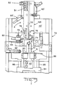
- the apparatus comprises a base plate 52 for mounting on a work table (not shown) and having secured thereto columns 54 supporting a platform 56, which in turn supports a mounting plate 58 carrying pneumatic manifolds 60 (one of which is shown), a vibratory bowl bung seal feeder 64 and a bracket 62 supporting the upper end of the magazine 4 which is connected to the bowl feeder 64 to receive bung seals down a track 66 of the magazine 4.
- the magazine 4 is bolted to a bracket 68 and to the forward plate 69 of a forward frame 70 on a base plate 50 by means of bolts 71, the plate so being secured to the plate 52 by means of screws 50′.
- Figure 3 shows the plate 69 with the bracket 68 removed.
- the track 66 opens on one side thereof into a slot 72 which is coextensive with the track 66 and is of smaller width than the track 66 and which receives the portions E of the seals BS, which are of reduced cross-section.
- the bottom of the track 66 as shown in Figure 2a, is open, the bottom of the slot 72, being normally closed by a pair of escapement plates 74 which are mounted to the magazine 4 by means of pivot pins 76 and are urged by springs 78 (one of which is shown in Figure 5) towards a position to close the bottom of the slot 72.
- the presence of a seal against the escapement plates 74 is monitored by means of an opto-electric sensor 80 adjustably secured in a block 81 by means of screws 79, the block 81 being secured to a vertically adjustable vane 83 on the frame 70.
- An adjustable pneumatic valve 82 causes compressed air to be continuously applied by way of a conduit 84 extending obliquely into the track 66, against the column of bung seals BS therein, thereby to urge the leading seal BS1 against the escapement plates 74, so that its jaws 40 of the seal clamp 8 can close about the leading seal BS1 at a position back from its end E, given that the bottom of the track 66 is open as mentioned above.
- An opto-electric sensor 82′ on a support 83′ detects the height of the column of seals BS in the track 66.
- the escapement plates 74 are forced, against the action of the springs 78, to open the bottom of slot 72 to allow the seal BS1 to escape from the magazine 4.
- a vane 86 on the seal clamp 8 cooperates with a sensor 88 on the frame 70 to detect the raised position of the seal clamp 8, a further vane 90 on the clamp 8 cooperating with a sensor 92 to detect the open position of the jaws 40.
- the clamp 8 is secured to a slide 94 having bushings 96, Figure 3, running on rods 98 secured at their lower ends in the base plate 50 and at their upper ends in brackets 100 fixed to the frame 70.
- the piston rod 38′ of the unit 38 is connected to the slide 94 by means of a coupling 94′.
- Adjustable stops 102 on the brackets 100 and adjustable stops 106 on the plate 50 cooperate to define the limits of the upper and lower positions of the seal clamp 8.
- the raised and lowered positions of the slide 94 are monitored by sensors 108 and 110, respectively, on the frame 70.
- the magazine 4 has an upper part 112 secured by bolts 114 to a vertical lower part 116 thereof fixed to the bracket 68.
- the pneumatic clamp unit 45 of the seal receptacle 6 is mounted to the forward side of the frame 70.
- the units 30 and 22 and the seal transfer device 10 are supported by a cylinder block 117 secured to the base plate 52 by means of bolts 120 ( Figures 1, 4 and 6).
- the piston rod 24 comprises a slide 118 in a slide housing 119 connected to the unit 22 by means of a coupling 121, the lug 26 being fixed to the leading end of the slide 118 by means of a screw 121.
- the retracted position of the piston rod 32 and thus of the pin 18 is determinable by means of adjustment stops 123 and 125 in an L-block 127, the piston rod 32 having a pad 129 ( Figure 1) cooperating therewith.
- a sensor 122 ( Figure 4) for sensing the retracted position of the piston rod 32 of the piston and cylinder unit 30 and thus of the pin 18.
- a sensor 124 cooperates with a vane 126 fixed to the lug 26 to sense the retracted position of the sleeve 14, as shown in Figure 4.
- the forward end position of the lug 26 and thus that of the sleeve 14, is limited by an adjustable stop 128 on the sleeve 12.
- the advanced position of the sleeve 14 is sensed by a sensor 130 on the frame 70.
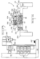
- the lead clamp 2 will now be described in outline with reference to Figures 1 and 7 to 12.
- the lead clamp 2 comprises a set of seven lead gripping jaws 134 and a set of four lead centering jaws 136. These sets of jaws can be opened and closed simultaneously by means of a pneumatic piston and cylinder drive unit 137 in a lead clamp support 138 on a carriage 139, on which lead clamp 2 is mounted in front of the apparatus.
- the jaws 136 do not serve to grip the lead L, which is slideable therebetween even when the jaws 136 are in a closed position.
- the jaws 136 are mounted so as to be slideable towards the jaws 134 against the action of coil springs 138 when the leading end 140 of the lead clamp 2 butts against the seal gripper 6, so that the leading end of the lead L is advanced to its correct length in the receptacle 6 as described above with reference to Figure 2e, the lead L sliding between the jaws 136 which, as mentioned above are centering, rather than gripping, jaws.
- the jaws 134 and 136 are mounted on respective support arms 142, which can be swung about the axes of pins 144, by means of the piston and cylinder unit 137, to move the jaws 134 and 136 between their open and their closed positions.
- the said work table can be raised and lowered to align the receptacle 6 with the lead clamp 2.
- Figures 7 and 8 show the lead clamp 2 in its normal uncompressed state, Figure 2d, whereas Figures 9 and 10 show it in its compressed state, Figures 2e and 2f, whilst Figure 12 shows the jaws both in their open and in their closed positions.
- the arms 142 each of which carries one array of jaws of each set of jaws 134 and 136, are each mounted to the longer leg 165 of an L-shaped swivel arm 166 by means of screws 168.
- Each swivel are 166 is pivoted, as shown in Figure 11, by means of one of the pins 144, at the junction between its legs 165 and 167, in a respective clevis 170 formed in a pivot block 172, as best seen in Figure 11 and 12.
- Each clevis 170 is partially closed by a swivel arm cover plate 171 secured to the block 172 by means of screws 173.
- each swivel arm 166 is pivoted by means of a pin 174 ( Figure 11) to a lug 176 at one end of a further swivel arm 178, the other end of which is pivoted by means of a pin 180 to a clevis 182 on a piston rod 184 of the piston and cylinder unit 137.
- the jaws 134 and 136 are opened as indicated by the arrows A in Figure 12, when the piston rod 184 is retracted and are closed when it is advanced.
- Each array of lead gripping jaws 134 is fixed to a cheek 186 on a respective support arm 142 of the clamp 2, each array of jaws of the lead centering jaws 136 being secured by means of a screw 188 to a slide 190, which is mounted for horizontal sliding movement in the respective cheek 186.
- the springs 138 against the action of which the jaws 136 are moved towards the jaws 134, when, as shown in Figures 9 and 10, the leading end 140 of the clamp 2 butts against the lead receptacle 6, are carried by rods 192 fixed in the slide 190 and which are slideable in the cheeks 186, as best seen in Figure 10.
- Vertical support plate 150 fixed by screws 150′ to the base plate 52 carries arrays of pneumatic valves 152 (most of which are shown in Figure 13) for the control of the servo devices described above for actuating the moveable parts of the apparatus, under the control of an electronic control circuit 154 mounted on the plate 52 and which supports an electronic control box 156 for the vibratory bowl feeder 64.
- the plate 150 also carries a pneumatic pressure control device 152′.
- the spacing between the sensors 124 and 130 can be adjusted by means of a slide arrangement 158 ( Figure 6).
- the open and closed positions of the jaws 44 of the seal receptacle 6 are detected by sensors 146 in cooperation with a vane 148 on one of the jaws 44.
- the sensors described above are all proximity switches excepting the opto-electrical sensors 80 and 82′.
- the sensor 80 serves to signal the control circuit 154 to stop further operation of the apparatus should no seal BS1 be present against the escapement plates 74.
- the sensor 82′ serves to signal the control box 156, when the height of the column of seals in the track 66 falls below the beam level of the sensor 82′, to start the bowl feeder 64.
- the sensor 122 which detects the retracted position of pin 18, signals the circuit 154 to step forward a counter 200 ( Figure 1) for counting the number of seals that have been applied to leads each time the pin 18 is returned to its retracted position.
- the sensors 146 which detect the open and the closed positions of the jaws 44 of the seal receptacle 6, signal the circuit 154 to initiate the next following step of the apparatus upon opening and closure, as the case may be, of the jaws 44.
- the sensor 124 serves to actuate the control circuit 154 to open the jaws 44 of the receptacle 6 when the sleeve 14 is retracted to its Figure 2f position.
- the lead making machine which comprises lead conveying jaws 162 ( Figure 1) is not otherwise shown in the drawings, the jaws 162 are moved by means of an endless conveyor chain in a direction perpendicular to the plane of Figure 1. Operation of the bung seal applying apparatus is initiated by pressing a start button 202 of the control circuit 154. Initially, the jaws 134 and 136 of the lead clamp 2 are open under the control of the lead making machine. When the jaws 162 which carry a lead L are in alignment with the open jaws 134 and 136, the lead making machine closes the jaws 134 and 136 about the lead L.
- the sensor 130 When the sleeve 14 is in its fully advanced Figure 2d position, the sensor 130 is actuated to signal the control circuit 154 to advance the lead clamp 2 to its Figure 2e fully advanced position, provided that the circuit 154 has received a signal from the lead making machine that the jaws 134 and 136 are, in fact, closed and that the jaws 162 have opened.
- the circuit 154 signals the lead making machine to retract the lead clamp 2, close the jaws 162 and open the jaws 134 and 136 of the lead clamp 2. The lead making machine then starts its conveyor to transfer the lead L to the crimping station.
- the jaws 44 of the receptacle 6 open, they activate the sensors 146 to cause the control circuit 154 to recycle the seal applying apparatus upon receipt of a signal from the lead making machine that the lead clamp 2 has been fully retracted to its starting position.
- the sensors 146 are actuated to cause the piston and cylinder unit 38 to be actuated by the circuit 154 to raise and lower the lead clamp 8 to position a further seal BS1 between the receptacle 6 and the transfer device 10.
- Each jaw 44 comprises an upright 204 secured by screws 206 to a respective slide block 208, the blocks 208 being driven horizontally towards and away from each other by the drive unit 45.
- Each upright 204 is fixed to an L-shaped support 210 to which is secured by screws 212 a jaw body member 214 to which is in turn secured an L-section slide housing 216 in which is contained, for horizontal sliding movement, a seal stop slide 218 formed with a blind bore 220 containing a spring 222, the springs 222 acting between the housings 216 and the slides 218 to urge the latter towards each other.
- the slides 218 In the closed position of the jaws 44, the slides 218 cooperate to define a flared seal entry mouth 224, the body members 214 cooperating to define a seal receiving opening 226. Each slide 218 has a seal abutment lip 228 at the seal entry end of the opening 226. Each support 210 has secured therein by screws 230, an insert 232 containing the respective half grommet 42′.
- the seal BS1 entering the mouth 224 urges the slides 218 away from each other against the action of the springs 222 which cause the slides 218 to resile when the seal BS1 has entered the opening 226, so that the lips 228 close behind the seal ensuring that it cannot back out as the sleeve 14 is retracted from its Figure 2e position to its Figure 2f position. This feature enables the diameter of the mouth 224 to be enlarged for easy insertion of the seal.
- the opto-electrical sensor 80 may be mounted to the magazine itself, with the working end of the sensor 80 proximate to the leading seal BS1.
Landscapes
- Engineering & Computer Science (AREA)
- Manufacturing & Machinery (AREA)
- Manufacturing Of Electrical Connectors (AREA)
- Insulated Conductors (AREA)
- Automatic Assembly (AREA)
- Fixed Capacitors And Capacitor Manufacturing Machines (AREA)
- Connector Housings Or Holding Contact Members (AREA)
Description
- This invention relates to apparatus for, and a method of, applying a hollow bung seal to an electrical lead.
- There is an increasing demand in the automotive industry for sealed electrical connectors. To this end, it is customary to seal the terminal receiving cavities of an insulating electrical connector housing by fitting the end of each lead to which an electrical terminal for insertion into a respective cavity is to be crimped, with a hollow bung seal.
- Since such bung seals are made of an elastomeric material and since they must fit tightly about the leads, it is both tedious and time consuming for the lead ends to be inserted through the bung seals manually.
- There is described in JP-A-59-154 783, apparatus for applying a hollow bung seal to an electrical lead, the apparatus comprising; a bung seal source; a bung seal receptacle for receiving a leading bung seal from the bung seal source; a bung seal transfer device comprising a guide structure supporting, for axial movement relative thereto, a bung seal expansion sleeve and a bung seal expansion pin within said sleeve; means for inserting an electrical lead into the sleeve; and drive means for sequentially causing; the expansion pin to enter and expand a bung seal in the bung seal receptacle; the sleeve to enter and further expand the bung seal; the expansion pin to be withdrawn from the bung seal leaving it secured to the sleeve by its own resilience and permitting a lead to be inserted into the sleeve by the lead insertion means; and the sleeve to be withdrawn from the bung seal leaving it secured to the lead by its own resilience.
- In this known apparatus, the bung seal transfer device is mounted on a turntable and is swung between a position opposite to a bung seal receptacle previously driven through a reciprocating movement to pick up the leading bung seal from the bung seal source, the bung seal transfer device with the bung seal on the expansion sleeve thereof then being swung by the turntable to a position opposite to the lead insertion means which is displaced by some ninety degrees about the axis of rotation of the turntable, from the bung seal receptacle.
- The present invention is intended to provide a straight action apparatus of the above kind in which the turntable is accordingly eliminated.
- According to one aspect of the present invention, therefore, apparatus as defined above, for applying a hollow bung seal to an electrical lead, is characterized in that the guide structure, the seal receptacle and the bung seal source are mounted in mutually fixed relationship, a bung seal transfer clamp being provided for withdrawing the leading bung seal from the bung seal source and placing it between the bung seal receptacle and the expansion pin, for transfer thereby into the bung seal receptacle, the lead insertion means being mounted for movement towards and away from the side of bung seal receptacle remote from the support structure.
- The need for mounting the bung seal transfer device comprising the guide structure and the bung seal expansion sleeve and expansion pin, on a turntable in order to enable the seal applying operation to be carried out, is accordingly avoided.
- The apparatus is especially intended for use as part of a harness making assembly comprising a lead making machine for supplying leads to the lead insertion means and for removing the leads with the seals thereon from the lead insertion means and transporting them to a crimping station at which electrical terminals are crimped thereto.
- In order to minimise, and to simplify, the movement of the bung seal transfer clamp, the bung seal source may have a bung seal outlet which is positioned proximate to the guide structure and the seal receptacle, seal gripping jaws of the seal clamp being moveable rectilinearly, between the guide structure and the seal receptacle, between a first position to close about the leading seal at the seal outlet and a second position to align the leading seal with the expansion pin and the seal receptacle.
- For ready extraction of the leading bung seal from the bung seal source, the bung seal source may comprise a magazine containing a column of bung seals, an end portion of the leading seal of the column being supported by a resiliently mounted escapement plate, the jaws of the seal clamp serving to grip the leading seal at a position back from said end portion in the first position of the seal clamp and to remove the leading seal from the magazine, against the resilient action of the escapement plate as the seal clamp is moved towards its second position.
- In the known apparatus, a separate, resilient seal stop is used against which the seal is driven by the expansion pin. Since such a stop would, if used in the present apparatus, obstruct the insertion of the lead to the expansion sleeve, the seal receptacle may contain a grommet through which the leading end of the expansion pin, and the lead can be passed, and which serves as an abutment against which the leading end of the seal is forced by the expansion pin, as it transfers the seal from the bung seal clamp into the bung seal receptacle. In order to facilitate entry of the seal into the seal receptacle, it may be provided with an enlarged mouth and spring loaded detent means for preventing the seal from backing out from the seal receptacle as the sleeve is withdrawn from the bung seal.
- In the interest of simplifying the drive means of the expansion pin and the expansion sleeve, as compared with the known apparatus, the support structure comprises a support sleeve fixed to a cylinder block on a base plate of the apparatus, in which sleeve the expansion sleeve and the expansion pin are slideably mounted, the expansion pin being driven by a first piston and cylinder unit fixed to the cylinder block in axial alignment with the support sleeve and the expansion sleeve being driven by a second piston and cylinder unit fixed in said block parallel with the first piston and cylinder unit. In this way the use of a complex linkage system for connecting the piston and cylinder units to the sleeve and the pin is rendered unnecessary. The second piston and cylinder unit may have its piston rod connected to a lug received in a notch in the expansion sleeve and which is moveable along an axial slot in the support sleeve.
- For inserting a sufficient length of the lead into the expansion sleeve, the lead insertion means may comprise a lead clamp having lead gripping jaws and lead centering jaws, and a drive unit for moving the lead clamp towards and away from the bung seal receptacle, the centering jaws being movable towards the gripping jaws against the action of resilient means, for the purpose of advancing the lead into the bung seal receptacle upon the lead clamp being urged thereagainst by its drive unit.
- If the lead clamp were to be advanced towards the seal receptacle with the lead projecting by said sufficient extent, the lead would tend to droop in front of the lead clamp so as to inhibit its insertion into the lead receptacle.
- According to another aspect of the invention, a method of applying a hollow bung seal to an electrical lead, which method comprises the steps of placing the bung seal in a bung seal receptacle; expanding the bung seal by inserting a first bung seal expansion member therethrough; further expanding the bung seal by inserting a second bung seal expansion member surrounding the first expansion member, between the first expansion member and the seal; withdrawing the first expansion member, leaving the seal secured by its own resilience to the second expansion member; inserting the lead into the second expansion member; and withdrawing the second expansion member, leaving the seal secured about the lead by its own resilience and removing the lead with the bung seal thereon, from the bung seal receptacle; characterized in that the seal is placed in the bung seal receptacle and the lead is inserted thereinto with the bung seal receptacle, the first and second expansion members, and the lead all in axial alignment.
- For a better understanding of the invention and to show how it may be carried into effect, reference will now be made by way of example to the accompanying drawings which are partly schematic or diagrammatic and in which;
- Figure 1 is a side view, shown partly in section and with parts omitted, of apparatus for applying a hollow bung seal to an electrical lead;
- Figures 2a to 2g are diagrammatic, fragmentary, longitudinal sectional views illustrating successive stages in the operation of the apparatus;
- Figure 2h is an enlarged side view of a bung seal which has been applied to an electrical lead and shows an electrical terminal crimped to the bung seal and to the lead;
- Figure 3 is a front view of the apparatus, shown partly in section, and with parts omitted;
- Figure 4 is a fragmentary top plan view of the apparatus with parts omitted;
- Figure 5 is an enlarged, fragmentary view shown partly in section, taken in the direction of the arrow X in Figure 1;
- Figure 6 is a fragmentary side view of Figure 5;
- Figure 7 is an enlarged, side view of a lead clamp of the apparatus, showing the lead clamp in an expanded, normal condition;
- Figure 8 is a top plan view of Figure 7, shown partly in section;
- Figure 9 is an enlarged side view of the lead clamp in a contracted condition, in abutment with a seal receptacle of the apparatus, which is shown diagrammatically;
- Figure 10 is a top plan view of Figure 9, shown partly in section;
- Figure 11 is an exploded, isometric view illustrating a drive mechanism for the lead clamp;
- Figure 12 is a front view of the lead clamp illustrating both open and closed position thereof;
- Figure 13 is an end view of a control valve support plate of the apparatus; and
- Figure 14 is an elevational view, partly in section, of a bung seal receptacle of the apparatus;
- The main working parts of the apparatus for applying a hollow bung seal to an electrical lead will now be described in outline with reference to Figure 1. These main parts comprise a
clamp 2 for an electrical lead L, a fixedbung seal magazine 4, a fixedbung seal receptacle 6, a bungseal transfer clamp 8, and a bungseal transfer device 10. Thedevice 10 comprises a support structure in the form of a fixedouter sleeve 12, slideably supporting therein a bung seal expansion,inner sleeve 14 having a reduced cross-section, taperednose 16, and which, in turn, slideably receives a bungseal expansion pin 18 having a tapered bungseal expansion nose 20 formed with a reduced cross-sectionguide end portion 21. Thesleeve 14 is arranged to be driven axially relative to thesleeve 12 by thepiston rod 24 of a pneumatic piston andcylinder unit 22, alug 26 on therod 24 engaging in anotch 28 in thesleeve 14 and in alongitudinal slot 29 in theouter sleeve 12. Thepin 18 is driven axially relative to thesleeves cylinder unit 30 by way of itspiston rod 32, alug 34 projecting rearwardly from thepin 18 engaging in anotch 36 in thepiston rod 32. The bungseal transfer clamp 8 is driven in vertical reciprocating motion by means of a pneumatic drive piston andcylinder unit 38,jaws 40 of theclamp 8 being opened and closed by means of a pneumatic piston andcylinder unit 42 by way of a linkage (not shown). Thelead clamp 2 which can be opened and closed by means described in detail below, is arranged to be driven towards and away from thereceptacle 6, by means of a pneumatic piston andcylinder unit 43 under the control of a lead making machine, for example a Komax K42 machine.Jaws 44 of theseal receptacle 6 are arranged to be opened and closed by means of apneumatic clamp unit 45 secured to asupport plate 45′. - The operation of the apparatus will now be described in outline with reference to Figures 2a to 2g. As shown in Figure 2a, the
magazine 4 contains a column of hollow bung seals BS made of an elastomeric material which have been fed into themagazine 4 by means described below. At the beginning of a cycle of the apparatus, thelead clamp 2 which has been closed about a lead L is in a retracted position shown in Figures 1 and 2d, remote from thebung seal receptacle 6, thesleeve 14 and thepin 18 each being in a retracted position as shown in Figures 1 and 2a. During a previous cycle of operation of the apparatus, theseal clamp 8 was raised rectilinearly by theunit 38 with itsjaws 40 in an open position to receive between them the leading bung seal BS1 in themagazine 4 and thejaws 40 were then closed thereabout by theunit 42 and theclamp 8 was lowered by theunit 38, to place the seal BS1 in axial alignment with thepin 18 and with theseal receptacle 6, as shown in Figure 2a. Upon actuation of the apparatus by a parent machine, in the present example said lead making machine, as described below, thesleeve 14 and thepin 18 are advanced by theirrespective drive units nose 20 of thepin 18 enters the seal BS1, theend portion 21 of thenose 20 acting as a guide, at which time, thejaws 40 of theseal transfer clamp 8 are opened by theunit 42 and thenose 20 pushes the seal BS1 into theseal receptacle 6 as shown in Figure 2b, so that the leading end of the seal BS1 butts against a pair ofresilient half grommets 42′ in therespective jaws 44 of theseal receptacle 6, which are in a closed position as shown in Figure 2b. Thesleeve 14 and thepin 18 are further advanced, in unison, by their drive units, so that, as shown in Figure 2c, the seal BS1 is radially expanded by thetapered nose 20 of thepin 18 thereby allowing thetapered nose 16 of thesleeve 14 to enter the seal BS1 so as further to expand it, and so as to extend slightly beyond its leading end, thenose 20 of thepin 18 passing through thehalf grommets 42′ to extend beyond theseal receptacle 6, as shown in Figure 2c. As will be apparent from that Figure, thetapered noses nose 16, by its own resilience so as tightly to grip it. As shown in Figure 2d, thepin 18 is then retracted by itsdrive unit 30, relative to thesleeve 14, which remains stationary with the seal BS1 secured thereto. Thelead clamp 2 carrying the lead L, the end part of the electrically conducted core, of which has been stripped of insulation by the parent machine, is then advanced as shown in Figure 2e, so as to butt against theseal receptacle 6 to insert the end portion of the lead L into thereceptacle 6 by way of a flared guidingmouth 46 thereof, and thus into thenose 16 of thesleeve 14, which is surrounded by the seal BS1. By reason of its abutment against thereceptacle 6, thelead clamp 2 is compressed, as explained in detail below, so that the lead L is advanced relative to thelead clamp 2 as shown in Figure 2e, to achieve full penetration of the lead L through the seal BS1. Thelead clamp 2 is arranged to advance the lead L in this way, since if the lead L were to be carried by theclamp 2, in its advanced position, it would tend to droop in front of theclamp 2 so that the lead end would not be correctly inserted into thereceptacle 6 and thesleeve 14. Thesleeve 14 is now retracted by its drive unit to its starting position, as shown in Figure 2f, thepin 18 also being in its starting position, thereby to withdraw thenose 16 of thesleeve 14 from the seal BS1 so that the latter resiles tightly to grip the insulation of the lead L in a position just back from the stripped end of the core C as shown in Figure 2f. As shown in Figure 2g, the receptacle 6 (shown as seen from above) and the lead clamp 2 (also shown as seen from above) are opened, so that the lead L within the seal BS1 resiliently secured thereto can be removed from the apparatus, and thelead clamp 2 is returned to its starting position and thejaws 44 of thereceptacle 6 are closed by theunit 45, so that when theclamp 8 has seized a further seal from themagazine 4 in the manner described above, the parts of the apparatus are in a starting position ready for the next cycle of the operation thereof. The parent machine transfers the lead L with the seal BS1 thereon, to a crimping station not shown where an insulation barrel B1 of an electrical terminal is crimped about the end portion E of the seal BS1, a crimping barrel B2 of the terminal being crimped about the stripped end of the core C as shown in Figure 2h. - The
lug 34 of thepin 18 projects from astop collar 35 thereon for engaging astop 37 on thesleeve 14, when thesleeve 14 and thestop 37 are in their Figures 2f and 2g positions. - The apparatus and its operation will now be described in more detail, with particular reference to Figures 1 and 3 to 12. The apparatus comprises a
base plate 52 for mounting on a work table (not shown) and having secured theretocolumns 54 supporting aplatform 56, which in turn supports amounting plate 58 carrying pneumatic manifolds 60 (one of which is shown), a vibratory bowlbung seal feeder 64 and abracket 62 supporting the upper end of themagazine 4 which is connected to thebowl feeder 64 to receive bung seals down atrack 66 of themagazine 4. Themagazine 4 is bolted to abracket 68 and to theforward plate 69 of aforward frame 70 on abase plate 50 by means ofbolts 71, the plate so being secured to theplate 52 by means ofscrews 50′. Figure 3 shows theplate 69 with thebracket 68 removed. As best seen in Figures 2a and 5, thetrack 66 opens on one side thereof into aslot 72 which is coextensive with thetrack 66 and is of smaller width than thetrack 66 and which receives the portions E of the seals BS, which are of reduced cross-section. The bottom of thetrack 66, as shown in Figure 2a, is open, the bottom of theslot 72, being normally closed by a pair ofescapement plates 74 which are mounted to themagazine 4 by means of pivot pins 76 and are urged by springs 78 (one of which is shown in Figure 5) towards a position to close the bottom of theslot 72. The presence of a seal against theescapement plates 74 is monitored by means of an opto-electric sensor 80 adjustably secured in ablock 81 by means ofscrews 79, theblock 81 being secured to a verticallyadjustable vane 83 on theframe 70. An adjustablepneumatic valve 82 causes compressed air to be continuously applied by way of aconduit 84 extending obliquely into thetrack 66, against the column of bung seals BS therein, thereby to urge the leading seal BS1 against theescapement plates 74, so that itsjaws 40 of theseal clamp 8 can close about the leading seal BS1 at a position back from its end E, given that the bottom of thetrack 66 is open as mentioned above. An opto-electric sensor 82′ on asupport 83′ detects the height of the column of seals BS in thetrack 66. As theseal clamp 8 is lowered towards the end position in which it is shown in Figure 2a, with thejaws 40 thereof closed about the leading seal BS1, theescapement plates 74 are forced, against the action of thesprings 78, to open the bottom ofslot 72 to allow the seal BS1 to escape from themagazine 4. Avane 86 on theseal clamp 8 cooperates with asensor 88 on theframe 70 to detect the raised position of theseal clamp 8, afurther vane 90 on theclamp 8 cooperating with asensor 92 to detect the open position of thejaws 40. Theclamp 8 is secured to aslide 94 havingbushings 96, Figure 3, running onrods 98 secured at their lower ends in thebase plate 50 and at their upper ends inbrackets 100 fixed to theframe 70. As best seen in Figure 1, thepiston rod 38′ of theunit 38 is connected to theslide 94 by means of acoupling 94′.Adjustable stops 102 on thebrackets 100 andadjustable stops 106 on theplate 50 cooperate to define the limits of the upper and lower positions of theseal clamp 8. The raised and lowered positions of theslide 94 are monitored bysensors frame 70. Themagazine 4 has anupper part 112 secured bybolts 114 to a verticallower part 116 thereof fixed to thebracket 68. - The
pneumatic clamp unit 45 of theseal receptacle 6 is mounted to the forward side of theframe 70. Theunits seal transfer device 10 are supported by acylinder block 117 secured to thebase plate 52 by means of bolts 120 (Figures 1, 4 and 6). Thepiston rod 24 comprises aslide 118 in aslide housing 119 connected to theunit 22 by means of acoupling 121, thelug 26 being fixed to the leading end of theslide 118 by means of ascrew 121. The retracted position of thepiston rod 32 and thus of thepin 18 is determinable by means of adjustment stops 123 and 125 in an L-block 127, thepiston rod 32 having a pad 129 (Figure 1) cooperating therewith. On theblock 117 is a sensor 122 (Figure 4) for sensing the retracted position of thepiston rod 32 of the piston andcylinder unit 30 and thus of thepin 18. Asensor 124 cooperates with avane 126 fixed to thelug 26 to sense the retracted position of thesleeve 14, as shown in Figure 4. The forward end position of thelug 26 and thus that of thesleeve 14, is limited by anadjustable stop 128 on thesleeve 12. The advanced position of thesleeve 14 is sensed by asensor 130 on theframe 70. - The
lead clamp 2 will now be described in outline with reference to Figures 1 and 7 to 12. Thelead clamp 2 comprises a set of seven leadgripping jaws 134 and a set of fourlead centering jaws 136. These sets of jaws can be opened and closed simultaneously by means of a pneumatic piston andcylinder drive unit 137 in alead clamp support 138 on acarriage 139, on whichlead clamp 2 is mounted in front of the apparatus. Thejaws 136 do not serve to grip the lead L, which is slideable therebetween even when thejaws 136 are in a closed position. There can be some play between thejaws 136 and the lead L since the centering of the lead L need not be precise in view of the provision of the guiding,mouth 46 of thereceptacle 6 and the fact that the bore of thesleeve 14 is somewhat oversized with respect to the gauge of the lead L. Thejaws 136 are mounted so as to be slideable towards thejaws 134 against the action ofcoil springs 138 when theleading end 140 of thelead clamp 2 butts against theseal gripper 6, so that the leading end of the lead L is advanced to its correct length in thereceptacle 6 as described above with reference to Figure 2e, the lead L sliding between thejaws 136 which, as mentioned above are centering, rather than gripping, jaws. Thejaws respective support arms 142, which can be swung about the axes ofpins 144, by means of the piston andcylinder unit 137, to move thejaws receptacle 6 with thelead clamp 2. - The
lead clamp 2 and its operation will now be described in greater detail. Figures 7 and 8 show thelead clamp 2 in its normal uncompressed state, Figure 2d, whereas Figures 9 and 10 show it in its compressed state, Figures 2e and 2f, whilst Figure 12 shows the jaws both in their open and in their closed positions. Thearms 142, each of which carries one array of jaws of each set ofjaws longer leg 165 of an L-shapedswivel arm 166 by means ofscrews 168. Each swivel are 166 is pivoted, as shown in Figure 11, by means of one of thepins 144, at the junction between itslegs respective clevis 170 formed in apivot block 172, as best seen in Figure 11 and 12. Eachclevis 170 is partially closed by a swivelarm cover plate 171 secured to theblock 172 by means ofscrews 173. Theshorter leg 167 of eachswivel arm 166 is pivoted by means of a pin 174 (Figure 11) to alug 176 at one end of afurther swivel arm 178, the other end of which is pivoted by means of apin 180 to aclevis 182 on apiston rod 184 of the piston andcylinder unit 137. Thus thejaws piston rod 184 is retracted and are closed when it is advanced. Each array of leadgripping jaws 134 is fixed to acheek 186 on arespective support arm 142 of theclamp 2, each array of jaws of thelead centering jaws 136 being secured by means of ascrew 188 to aslide 190, which is mounted for horizontal sliding movement in therespective cheek 186. Thesprings 138 against the action of which thejaws 136 are moved towards thejaws 134, when, as shown in Figures 9 and 10, theleading end 140 of theclamp 2 butts against thelead receptacle 6, are carried byrods 192 fixed in theslide 190 and which are slideable in thecheeks 186, as best seen in Figure 10. -
Vertical support plate 150 fixed byscrews 150′ to thebase plate 52 carries arrays of pneumatic valves 152 (most of which are shown in Figure 13) for the control of the servo devices described above for actuating the moveable parts of the apparatus, under the control of anelectronic control circuit 154 mounted on theplate 52 and which supports anelectronic control box 156 for thevibratory bowl feeder 64. Theplate 150 also carries a pneumaticpressure control device 152′. - The spacing between the
sensors jaws 44 of theseal receptacle 6 are detected bysensors 146 in cooperation with avane 148 on one of thejaws 44. - The sensors described above are all proximity switches excepting the opto-
electrical sensors sensor 80 serves to signal thecontrol circuit 154 to stop further operation of the apparatus should no seal BS1 be present against theescapement plates 74. Thesensor 82′ serves to signal thecontrol box 156, when the height of the column of seals in thetrack 66 falls below the beam level of thesensor 82′, to start thebowl feeder 64. Thesensor 122, which detects the retracted position ofpin 18, signals thecircuit 154 to step forward a counter 200 (Figure 1) for counting the number of seals that have been applied to leads each time thepin 18 is returned to its retracted position. Thesensors 146, which detect the open and the closed positions of thejaws 44 of theseal receptacle 6, signal thecircuit 154 to initiate the next following step of the apparatus upon opening and closure, as the case may be, of thejaws 44. Thesensor 124 serves to actuate thecontrol circuit 154 to open thejaws 44 of thereceptacle 6 when thesleeve 14 is retracted to its Figure 2f position. - The lead making machine which comprises lead conveying jaws 162 (Figure 1) is not otherwise shown in the drawings, the
jaws 162 are moved by means of an endless conveyor chain in a direction perpendicular to the plane of Figure 1. Operation of the bung seal applying apparatus is initiated by pressing astart button 202 of thecontrol circuit 154. Initially, thejaws lead clamp 2 are open under the control of the lead making machine. When thejaws 162 which carry a lead L are in alignment with theopen jaws jaws sleeve 14 is in its fully advanced Figure 2d position, thesensor 130 is actuated to signal thecontrol circuit 154 to advance thelead clamp 2 to its Figure 2e fully advanced position, provided that thecircuit 154 has received a signal from the lead making machine that thejaws jaws 162 have opened. When thejaws 44 of thelead receptacle 6 have been opened by thecontrol circuit 154 upon thesensor 124 being actuated by thevane 126, thecircuit 154 signals the lead making machine to retract thelead clamp 2, close thejaws 162 and open thejaws lead clamp 2. The lead making machine then starts its conveyor to transfer the lead L to the crimping station. As thejaws 44 of thereceptacle 6 open, they activate thesensors 146 to cause thecontrol circuit 154 to recycle the seal applying apparatus upon receipt of a signal from the lead making machine that thelead clamp 2 has been fully retracted to its starting position. When thejaws 44 are thereby closed, thesensors 146 are actuated to cause the piston andcylinder unit 38 to be actuated by thecircuit 154 to raise and lower thelead clamp 8 to position a further seal BS1 between thereceptacle 6 and thetransfer device 10. - The
bung seal receptacle 6, which has so far been described only when in diagrammatic form, will now be described in more detail with particular reference to Figure 14 and also with reference to Figures 1, 3 and 4. Eachjaw 44 comprises an upright 204 secured byscrews 206 to arespective slide block 208, theblocks 208 being driven horizontally towards and away from each other by thedrive unit 45. Eachupright 204 is fixed to an L-shapedsupport 210 to which is secured by screws 212 ajaw body member 214 to which is in turn secured an L-section slide housing 216 in which is contained, for horizontal sliding movement, aseal stop slide 218 formed with ablind bore 220 containing aspring 222, thesprings 222 acting between thehousings 216 and theslides 218 to urge the latter towards each other. In the closed position of thejaws 44, theslides 218 cooperate to define a flaredseal entry mouth 224, thebody members 214 cooperating to define aseal receiving opening 226. Eachslide 218 has aseal abutment lip 228 at the seal entry end of theopening 226. Eachsupport 210 has secured therein byscrews 230, aninsert 232 containing therespective half grommet 42′. The seal BS1 entering themouth 224 urges theslides 218 away from each other against the action of thesprings 222 which cause theslides 218 to resile when the seal BS1 has entered theopening 226, so that thelips 228 close behind the seal ensuring that it cannot back out as thesleeve 14 is retracted from its Figure 2e position to its Figure 2f position. This feature enables the diameter of themouth 224 to be enlarged for easy insertion of the seal. - If the seals BS are dark in colour and so reflect little light, the opto-
electrical sensor 80 may be mounted to the magazine itself, with the working end of thesensor 80 proximate to the leading seal BS1.
Claims (10)
- Apparatus for applying a hollow bung seal to an electrical lead, the apparatus comprising; a bung seal source (4); a bung seal receptacle (6) for receiving a leading bung seal (BS1) from the bung seal source (4); a bung seal transfer device (10) comprising a guide structure (12) supporting for axial movement relative thereto, a bung seal expansion sleeve (14) and a bung seal expansion pin (18) within said sleeve (14); means (2) for inserting an electrical lead (L) into the sleeve (14); and drive means (22, 30) for sequentially causing; the expansion pin (18) to enter and expand the bung seal(BS1) in the bung seal receptacle (6): the sleeve (14) to enter and further expand the bung seal (BS1); the expansion pin (18) to be withdrawn from the bung seal (BS1) leaving it secured to the sleeve (14) by its own resilience, and permitting a lead (L) to be inserted into the sleeve (14) by the lead insertion means (2); and the sleeve (14) to be withdrawn from the bung seal (BS1) leaving it secured to the lead (L) by its own resilience; characterized in that the guide structure (12), the seal receptacle (6) and the bung seal source (4) are mounted in mutually fixed relationship, a bung seal transfer clamp (8) being provided for withdrawing the leading seal (BS1) from the bung seal source (4) and placing it between the bung seal receptacle (6) and the expansion pin (18) for transfer thereby into the bung seal receptacle (6), the lead insertion means (2) being mounted for movement towards and away from the side of the bung seal receptacle (6) remote from the guide structure (12).
- Apparatus according to claim 1, characterized in that the bung seal source (4) has a bung seal outlet (74) proximate to the guide structure (12) and the seal receptacle (6), seal gripping jaws (40) of the seal clamp (8) being moveable rectilinearly between the guide structure (12) and the seal receptacle (6), between a first position to close about the leading seal (BS1) at the seal outlet (74) and a second position to align the leading seal (BS1) with the expansion pin (18) and the seal receptacle (6).
- Apparatus according to claim 2, characterized in that the seal source comprises a magazine (4) containing a column of bung seals (BS), an end portion of the leading seal (BS1) of the column being supported by a resiliently mounted escapement plate (74), the jaws (40) of the seal clamp (8) serving to grip the leading seal (BS1) at a position back from said end portion (E) in the first position of the seal clamp (8), and to remove the leading seal (BS1) from the magazine (4) against the resilient action of the escapement plate (74) as the seal clamp (8) is moved towards its second position.
- Apparatus according to claim 3, characterized in that the magazine (4) defines a vertical track (66) one side of which opens into a slot (72) coextensive with the track (66) and of smaller width than the track (66) and which receives reduced cross section portions (E) of the seals (BS), the bottom end of the slot (72) being normally closed by said escapement plate (74) and the bottom end of the track (66) being open to receive the jaws (40) of the seal clamp (8).
- Apparatus according to any one of the preceding claims, characterized in that the seal receptacle (6) comprises a pair of jaws (44), having an open and a closed position and containing resilient members (42′) which, in the closed position of the jaws, co-operate to provide a grommet through which the leading end (20) of the expansion pin (18) and the lead (L) can be passed, and which serves as an abutment against which the leading end of the seal (BS1) is forced by the expansion pin (18) when it has transferred the seal (BS1) from the bung seal clamp (8) to the bung seal receptacle (6).
- Apparatus according to claim 5, characterized in that the seal receptacle (6) has a seal receiving mouth (224) defined in the closed position of the jaws (44), by a pair of spring loaded members (218) formed with lips (228) facing the resilient members (42′) and which close behind the seal BS1 when it has been inserted into the seal receptacle through the mouth (224).
- Apparatus according to any one of the preceding claims, characterized in that the guide structure comprises a support sleeve (12) fixed to a cylinder block (117) on a baseplate (52) of the apparatus and in which the expansion sleeve (14) and the expansion pin (18) are slideably mounted, the expansion pin (18) being driven by a first piston and cylinder unit (30) fixed to the block (117) in axial alignment with the support sleeve (12) and the expansion sleeve (14) being driven by a second piston and cylinder unit (22) fixed to the cylinder block (117) parallel with the first piston and cylinder unit (30).
- Apparatus according to claim 7, characterized in that the second piston and cylinder unit (22) has a piston rod (24) which is connected to a lug (28) received in a notch (28) in the expansion sleeve (14) and which is moveable along an axial slot (29) in the support sleeve (12).
- Apparatus according to any one of the preceding claims, characterized in that the lead insertion means comprises a lead clamp (2) having lead gripping jaws (134) and lead centering jaws (136), means for opening and closing these jaws, and a drive unit (43) for moving the lead clamp (2) towards and away from the bung seal receptacle (6), the centering jaws (136) being movable towards the gripping jaws (134) against the action of resilient means (138), for the purpose of advancing the lead (L) into the bung seal receptacle (6), upon the lead clamp (2) being urged thereagainst by the drive unit (43).
- A method of applying a hollow bung seal to an electrical lead, which method comprises the steps of, placing the bung seal (BS1) in a bung seal receptacle (6); expanding the bung seal (BS1) by inserting a first bung seal expansion member (18) therethrough further expanding the bung seal (BS1) by inserting a second bung seal expansion member (14) surrounding the first expansion member (18), between the first expansion member (18) and said seal (BS1); withdrawing the first expansion member (18) leaving the seal (BS1) secured by its own resilience to the second expansion member (14); inserting the lead (L) into the second expansion member (14); and withdrawing the second expansion member (14) leaving the seal (BS1) secured about the lead (L) by its own resilience; and removing the lead (L) with the bung seal (BS1) thereon, from the receptacle (6); characterized in that the seal (BS1) is placed in the bung seal receptacle (6), and the lead (L) is inserted therein, with the bung seal receptacle (6), the first and second expansion members (14 and 18),and the lead (L) all in axial alignment.
Applications Claiming Priority (2)
| Application Number | Priority Date | Filing Date | Title |
|---|---|---|---|
| GB8917145 | 1989-07-27 | ||
| GB898917145A GB8917145D0 (en) | 1989-07-27 | 1989-07-27 | Applying a bung seal to an electrical lead |
Publications (3)
| Publication Number | Publication Date |
|---|---|
| EP0410416A2 EP0410416A2 (en) | 1991-01-30 |
| EP0410416A3 EP0410416A3 (en) | 1993-01-13 |
| EP0410416B1 true EP0410416B1 (en) | 1995-06-14 |
Family
ID=10660699
Family Applications (1)
| Application Number | Title | Priority Date | Filing Date |
|---|---|---|---|
| EP90114260A Expired - Lifetime EP0410416B1 (en) | 1989-07-27 | 1990-07-25 | Applying a bung seal to an electrical lead |
Country Status (8)
| Country | Link |
|---|---|
| US (1) | US5016346A (en) |
| EP (1) | EP0410416B1 (en) |
| JP (1) | JP3012670B2 (en) |
| KR (1) | KR100191103B1 (en) |
| BR (1) | BR9003607A (en) |
| DE (1) | DE69020059T2 (en) |
| ES (1) | ES2073484T3 (en) |
| GB (1) | GB8917145D0 (en) |
Cited By (1)
| Publication number | Priority date | Publication date | Assignee | Title |
|---|---|---|---|---|
| EP2372848A1 (en) | 2010-03-30 | 2011-10-05 | Komax Holding AG | Device and method for equipping cables with grommets |
Families Citing this family (32)
| Publication number | Priority date | Publication date | Assignee | Title |
|---|---|---|---|---|
| US5155892A (en) * | 1991-01-31 | 1992-10-20 | King Jeffrey R | Hydraulic cylinder assembly process and machine |
| EP0534106B1 (en) * | 1991-09-25 | 1996-03-06 | Komax Holding Ag | Device for applying grommets to electrical cables |
| JPH05116039A (en) * | 1991-10-29 | 1993-05-14 | Canon Inc | Method and device for mounting elastic annular body |
| JP2635487B2 (en) * | 1992-08-31 | 1997-07-30 | 矢崎総業株式会社 | How to attach rubber stopper to electric wire |
| CH689272A5 (en) * | 1993-05-06 | 1999-01-15 | Komax Holding Ag | Device for fitting sleeves of electric cables. |
| SE503278C2 (en) * | 1993-06-07 | 1996-05-13 | Kabeldon Ab | Method of jointing two cable parts, as well as joint body and mounting tool for use in the process |
| JP3028734B2 (en) * | 1994-09-12 | 2000-04-04 | 住友電装株式会社 | Rubber stopper holder of rubber stopper insertion machine |
| US5697521A (en) * | 1995-06-01 | 1997-12-16 | Huck International | Hand-held collar dispenser |
| JPH09290332A (en) * | 1996-03-01 | 1997-11-11 | Yazaki Corp | Rubber stopper inserting device, rubber stopper supplying method, and rubber stopper inserting method |
| JP3247069B2 (en) | 1997-03-18 | 2002-01-15 | 矢崎総業株式会社 | Terminal crimping device for wire with waterproof plug |
| US5901438A (en) * | 1997-04-29 | 1999-05-11 | Sumitomo Wiring Systems, Ltd. | Apparatus and method for introducing cables into or through a part |
| JP3573987B2 (en) * | 1998-12-18 | 2004-10-06 | 矢崎総業株式会社 | Rubber stopper insertion device |
| DE59908252D1 (en) * | 1999-01-19 | 2004-02-12 | Pawo Systems Ag Unteraegeri | Method and device for fitting spouts |
| KR100429062B1 (en) * | 2001-08-13 | 2004-04-29 | 제일모직주식회사 | Thermoplastic Resin Composition With Good Transparent and Impact Strength and Method for Preparing the Same |
| US7047618B2 (en) * | 2003-03-14 | 2006-05-23 | Whitney Systems, Inc. | Single stroke O-ring insertion device |
| DE502006002037D1 (en) * | 2005-02-07 | 2008-12-24 | Komax Holding Ag | Device for bushing of electrical cables |
| EP1689049B1 (en) * | 2005-02-07 | 2008-11-12 | komax Holding AG | Device for applying grommets to electrical cables |
| JP2008167592A (en) * | 2006-12-28 | 2008-07-17 | Tyco Electronics Amp Kk | Seal member mounting device |
| EP2320527B1 (en) * | 2009-11-09 | 2012-08-01 | Schäfer Werkzeug- und Sondermaschinenbau GmbH | Machine for mounting grommets |
| EP2362508B1 (en) * | 2010-02-04 | 2016-02-03 | Delphi Technologies, Inc. | Method for sheathing an electrical wire with an elastic sealing element |
| RU2013101776A (en) | 2010-06-16 | 2014-07-27 | Шлойнигер Холдинг Аг | DEVICE FOR INSTALLING CABLE TERMINALS ON A CABLE |
| US9352430B2 (en) * | 2010-06-16 | 2016-05-31 | Schleuniger Holding Ag | Cable grommet fitting apparatus for cable |
| BR112014007626A2 (en) | 2011-09-29 | 2017-04-11 | Schleuniger Holding Ag | method for attaching a sealed cable, sealing transfer unit or comparable cable gland components to a cable processing installation, and cable gland transfer process |
| CN102555598B (en) | 2011-12-29 | 2015-02-04 | 贝发集团股份有限公司 | Flat pen automatic assembly line |
| CN102529505B (en) | 2011-12-29 | 2014-05-07 | 贝发集团股份有限公司 | Vibrating machine used for uniformly filling granular ornaments |
| CN102529506B (en) * | 2011-12-31 | 2014-05-07 | 贝发集团股份有限公司 | Pen point dotting machine |
| EP2709217B1 (en) | 2012-09-12 | 2017-08-09 | Schleuniger Holding AG | Machine for assembling cable sleeves |
| CN107717374B (en) * | 2017-09-27 | 2019-04-12 | 湖南瑞森可机器人科技有限公司 | A kind of equipment and its device, assemble method assembling linear sealing strip |
| RS63045B1 (en) * | 2018-11-06 | 2022-04-29 | Komax Holding Ag | Grommet station |
| WO2020115535A1 (en) * | 2018-12-07 | 2020-06-11 | Schleuniger Holding Ag | Cable processing machine, device and method for expanding a sleeve |
| WO2021018592A1 (en) * | 2019-07-30 | 2021-02-04 | Metzner Maschinenbau Gmbh | Method, device and system for manufacturing an electric cable |
| DE102022003790B3 (en) | 2022-10-14 | 2023-11-16 | Mercedes-Benz Group AG | Device and method for carrying out an electrical line through a channel that is completely closed on the circumference |
Family Cites Families (8)
| Publication number | Priority date | Publication date | Assignee | Title |
|---|---|---|---|---|
| US2683924A (en) * | 1949-12-30 | 1954-07-20 | Gen Motors Corp | Machine for assembling nipples on cables |
| US3605239A (en) * | 1969-01-18 | 1971-09-20 | Dick Gordon Rockwell | Apparatus for external installation of resilient seals |
| US3665578A (en) * | 1970-05-18 | 1972-05-30 | Air Way Mfg Co | O-ring mounting machine |
| US4255479A (en) * | 1979-02-02 | 1981-03-10 | Industrial Electronic Rubber Co. | Method of manufacturing cable seals |
| JPS59154783A (en) * | 1983-02-21 | 1984-09-03 | アンプ インコーポレーテッド | Apparatus for mounting hollow sealing plug on wire terminal |
| US4653182A (en) * | 1984-04-17 | 1987-03-31 | Sumitomo Electric Industries, Ltd. | Apparatus for fitting terminals and rubber stoppers on wires |
| US4832555A (en) * | 1988-03-18 | 1989-05-23 | Gordon John H | Gasket holding and feeding magazine |
| DE3823720A1 (en) * | 1988-07-13 | 1990-01-18 | Grote & Hartmann | METHOD AND DEVICE FOR MECHANICAL APPLICATION OF SEALING PLUGS TO ELECTRICAL LINES |
-
1989
- 1989-07-27 GB GB898917145A patent/GB8917145D0/en active Pending
-
1990
- 1990-07-20 US US07/556,061 patent/US5016346A/en not_active Expired - Lifetime
- 1990-07-25 BR BR909003607A patent/BR9003607A/en not_active IP Right Cessation
- 1990-07-25 EP EP90114260A patent/EP0410416B1/en not_active Expired - Lifetime
- 1990-07-25 ES ES90114260T patent/ES2073484T3/en not_active Expired - Lifetime
- 1990-07-25 DE DE69020059T patent/DE69020059T2/en not_active Expired - Fee Related
- 1990-07-26 KR KR1019900011367A patent/KR100191103B1/en not_active Expired - Fee Related
- 1990-07-27 JP JP2201090A patent/JP3012670B2/en not_active Expired - Lifetime
Cited By (1)
| Publication number | Priority date | Publication date | Assignee | Title |
|---|---|---|---|---|
| EP2372848A1 (en) | 2010-03-30 | 2011-10-05 | Komax Holding AG | Device and method for equipping cables with grommets |
Also Published As
| Publication number | Publication date |
|---|---|
| DE69020059D1 (en) | 1995-07-20 |
| ES2073484T3 (en) | 1995-08-16 |
| EP0410416A3 (en) | 1993-01-13 |
| JPH0364881A (en) | 1991-03-20 |
| GB8917145D0 (en) | 1989-09-13 |
| DE69020059T2 (en) | 1995-09-21 |
| KR100191103B1 (en) | 1999-06-15 |
| JP3012670B2 (en) | 2000-02-28 |
| EP0410416A2 (en) | 1991-01-30 |
| KR910003870A (en) | 1991-02-28 |
| BR9003607A (en) | 1991-08-27 |
| US5016346A (en) | 1991-05-21 |
Similar Documents
| Publication | Publication Date | Title |
|---|---|---|
| EP0410416B1 (en) | Applying a bung seal to an electrical lead | |
| EP0452771B1 (en) | Alignment apparatus for positioning a connector housing during wire insertion | |
| EP0117273B1 (en) | Apparatus for automatically attaching terminals to cable ends | |
| US5537741A (en) | Method of wire harness assembly system | |
| US4653159A (en) | Flexible automated manufacturing system | |
| US5157830A (en) | Method for automatically connecting electric conductors with contact parts to connector shells | |
| US3553814A (en) | Terminal applicator for terminals in strip form | |
| JP3076079B2 (en) | Apparatus and method for automatically connecting an electrical conductor with contact parts to a connector shell | |
| US7024760B2 (en) | Method and apparatus for equipping plug housings with fitted-out cable ends of a cable | |
| US5315757A (en) | Apparatus for fitting of grommets to electrical cables | |
| EP0330309A2 (en) | Crimped wire harness fabricator and method | |
| US4683636A (en) | Wire preparation system | |
| JPS61173412A (en) | Flexible automatic manufacturing equipment for wire harnesses | |
| US4779334A (en) | Apparatus for inserting terminals on the ends of wires into cavities in an electrical connector | |
| EP0881720B1 (en) | Apparatus for assembling grommet to lead | |
| US4628594A (en) | Electronic circuit element insertion apparatus | |
| US11482823B2 (en) | Grommet station | |
| CN113690102A (en) | Automatic terminal plugging equipment | |
| EP1775804B1 (en) | Apparatus for producing an electrical wiring | |
| US5210942A (en) | Method for producing cable harnesses | |
| US4949451A (en) | Device for plugging contacts into a connector box | |
| CN215184979U (en) | A accurate direction auxiliary device that is used for pencil terminal and connector to assemble | |
| JP2578553B2 (en) | Power cord manufacturing method and device | |
| CN220323379U (en) | Chip box socket detection device | |
| EP0227742A1 (en) | Applicator for applying an electrical connector to a cable |
Legal Events
| Date | Code | Title | Description |
|---|---|---|---|
| PUAI | Public reference made under article 153(3) epc to a published international application that has entered the european phase |
Free format text: ORIGINAL CODE: 0009012 |
|
| AK | Designated contracting states |
Kind code of ref document: A2 Designated state(s): DE ES FR GB IT NL |
|
| 17P | Request for examination filed |
Effective date: 19901220 |
|
| PUAL | Search report despatched |
Free format text: ORIGINAL CODE: 0009013 |
|
| RAP1 | Party data changed (applicant data changed or rights of an application transferred) |
Owner name: THE WHITAKER CORPORATION |
|
| AK | Designated contracting states |
Kind code of ref document: A3 Designated state(s): DE ES FR GB IT NL |
|
| 17Q | First examination report despatched |
Effective date: 19940527 |
|
| GRAA | (expected) grant |
Free format text: ORIGINAL CODE: 0009210 |
|
| AK | Designated contracting states |
Kind code of ref document: B1 Designated state(s): DE ES FR GB IT NL |
|
| REF | Corresponds to: |
Ref document number: 69020059 Country of ref document: DE Date of ref document: 19950720 |
|
| ET | Fr: translation filed | ||
| REG | Reference to a national code |
Ref country code: ES Ref legal event code: FG2A Ref document number: 2073484 Country of ref document: ES Kind code of ref document: T3 |
|
| ITF | It: translation for a ep patent filed | ||
| PLBE | No opposition filed within time limit |
Free format text: ORIGINAL CODE: 0009261 |
|
| STAA | Information on the status of an ep patent application or granted ep patent |
Free format text: STATUS: NO OPPOSITION FILED WITHIN TIME LIMIT |
|
| 26N | No opposition filed | ||
| PGFP | Annual fee paid to national office [announced via postgrant information from national office to epo] |
Ref country code: NL Payment date: 19990630 Year of fee payment: 10 |
|
| PG25 | Lapsed in a contracting state [announced via postgrant information from national office to epo] |
Ref country code: NL Free format text: LAPSE BECAUSE OF NON-PAYMENT OF DUE FEES Effective date: 20010201 |
|
| NLV4 | Nl: lapsed or anulled due to non-payment of the annual fee |
Effective date: 20010201 |
|
| REG | Reference to a national code |
Ref country code: GB Ref legal event code: IF02 |
|
| PGFP | Annual fee paid to national office [announced via postgrant information from national office to epo] |
Ref country code: GB Payment date: 20040615 Year of fee payment: 15 |
|
| PGFP | Annual fee paid to national office [announced via postgrant information from national office to epo] |
Ref country code: FR Payment date: 20040702 Year of fee payment: 15 |
|
| PGFP | Annual fee paid to national office [announced via postgrant information from national office to epo] |
Ref country code: ES Payment date: 20040720 Year of fee payment: 15 |
|
| PGFP | Annual fee paid to national office [announced via postgrant information from national office to epo] |
Ref country code: DE Payment date: 20040730 Year of fee payment: 15 |
|
| PG25 | Lapsed in a contracting state [announced via postgrant information from national office to epo] |
Ref country code: IT Free format text: LAPSE BECAUSE OF NON-PAYMENT OF DUE FEES;WARNING: LAPSES OF ITALIAN PATENTS WITH EFFECTIVE DATE BEFORE 2007 MAY HAVE OCCURRED AT ANY TIME BEFORE 2007. THE CORRECT EFFECTIVE DATE MAY BE DIFFERENT FROM THE ONE RECORDED. Effective date: 20050725 Ref country code: GB Free format text: LAPSE BECAUSE OF NON-PAYMENT OF DUE FEES Effective date: 20050725 |
|
| PG25 | Lapsed in a contracting state [announced via postgrant information from national office to epo] |
Ref country code: ES Free format text: LAPSE BECAUSE OF NON-PAYMENT OF DUE FEES Effective date: 20050726 |
|
| PG25 | Lapsed in a contracting state [announced via postgrant information from national office to epo] |
Ref country code: DE Free format text: LAPSE BECAUSE OF NON-PAYMENT OF DUE FEES Effective date: 20060201 |
|
| GBPC | Gb: european patent ceased through non-payment of renewal fee |
Effective date: 20050725 |
|
| PG25 | Lapsed in a contracting state [announced via postgrant information from national office to epo] |
Ref country code: FR Free format text: LAPSE BECAUSE OF NON-PAYMENT OF DUE FEES Effective date: 20060331 |
|
| REG | Reference to a national code |
Ref country code: FR Ref legal event code: ST Effective date: 20060331 |
|
| REG | Reference to a national code |
Ref country code: ES Ref legal event code: FD2A Effective date: 20050726 |