EP0408942B1 - Apparatus for cutting and feeding thin web lengths - Google Patents
Apparatus for cutting and feeding thin web lengths Download PDFInfo
- Publication number
- EP0408942B1 EP0408942B1 EP90112317A EP90112317A EP0408942B1 EP 0408942 B1 EP0408942 B1 EP 0408942B1 EP 90112317 A EP90112317 A EP 90112317A EP 90112317 A EP90112317 A EP 90112317A EP 0408942 B1 EP0408942 B1 EP 0408942B1
- Authority
- EP
- European Patent Office
- Prior art keywords
- thin web
- revolving cutter
- counterblade
- cutter
- rollers
- Prior art date
- Legal status (The legal status is an assumption and is not a legal conclusion. Google has not performed a legal analysis and makes no representation as to the accuracy of the status listed.)
- Expired - Lifetime
Links
- 238000005520 cutting process Methods 0.000 title claims abstract description 17
- 230000033001 locomotion Effects 0.000 claims description 21
- 238000012856 packing Methods 0.000 claims description 3
- 230000001360 synchronised effect Effects 0.000 claims 1
- 238000004806 packaging method and process Methods 0.000 abstract description 2
- 230000005540 biological transmission Effects 0.000 description 2
- 238000011144 upstream manufacturing Methods 0.000 description 2
- 230000001133 acceleration Effects 0.000 description 1
- XAGFODPZIPBFFR-UHFFFAOYSA-N aluminium Chemical compound [Al] XAGFODPZIPBFFR-UHFFFAOYSA-N 0.000 description 1
- 229910052782 aluminium Inorganic materials 0.000 description 1
- 230000002547 anomalous effect Effects 0.000 description 1
- 230000001419 dependent effect Effects 0.000 description 1
- 230000003472 neutralizing effect Effects 0.000 description 1
Images


Classifications
-
- B—PERFORMING OPERATIONS; TRANSPORTING
- B65—CONVEYING; PACKING; STORING; HANDLING THIN OR FILAMENTARY MATERIAL
- B65B—MACHINES, APPARATUS OR DEVICES FOR, OR METHODS OF, PACKAGING ARTICLES OR MATERIALS; UNPACKING
- B65B61/00—Auxiliary devices, not otherwise provided for, for operating on sheets, blanks, webs, binding material, containers or packages
- B65B61/04—Auxiliary devices, not otherwise provided for, for operating on sheets, blanks, webs, binding material, containers or packages for severing webs, or for separating joined packages
- B65B61/06—Auxiliary devices, not otherwise provided for, for operating on sheets, blanks, webs, binding material, containers or packages for severing webs, or for separating joined packages by cutting
- B65B61/08—Auxiliary devices, not otherwise provided for, for operating on sheets, blanks, webs, binding material, containers or packages for severing webs, or for separating joined packages by cutting using rotary cutters
Definitions
- the invention concernes an apparatus for cutting and feeding thin web lengths, which is provided particularly in a machine for packing articles into lengths of a heat-contractible thin web and showing the features of the preamble of claim 1.
- a continuous thin web is fed vertically by a pair of counter-rotating, parallel feed-rollers to a cutting device, comprising a revolving cutter and a cooperating, stationary counterblade.
- the revolving cutter shows a revolving support for a radial blade, whose axis of rotation is fixed relatively to the counterblade.
- the blade fastened thereon is brought in a position coacting with the counterblade.
- an appartus of the aforementioned kind in which the revolving cutter is driven by a motor in an intermittent operative mode, comprising means, for example a friction clutch and a break, which are so provided that after the balde of the revolving cutter having caused to make a cut in the thin web, the said revolving cutter will be stopped in a position, in which the same does not interfere with the thin web, and in which it is ready for being again operated and moved into its motor-interlocked condition, so that the blade is caused to cut the successive thin web section.
- means for example a friction clutch and a break
- the invention aims to obviate the aforementioned inconvenients.
- the invention achieves this aim with an apparatus for cutting and feeding thin web lengths according to the preamble of claim 1 which further comprises the features of the characterizing part of claim 1.
- the lifting and lowering system carrying the revolving cutter causes this revolving cutter to make a cut in the thin web, when this revolving cutter is moved into its down position, while when no cutting in the thin web is to be made, the said revolving cutter is lifted and kept rotating at a suitable, preferably low speed.
- Down-stream of the cutting apparatus the thin web is pulled forward by two pairs of rollers by which the thin web is kept stretched as required. The speed of rotation of said roller pairs can be changed so as to have the thin web pulled through the cutting apparatus by the needed amount each time, before the revolving cutter is lowered down against the counterblade and caused to make a cut in the thin web with the blade thereof.
- the apparatus according to the invention is made capable to feed thin web sections of any desired length and at any speed. Also a possible variation in the speed of the thin web-entraining roller pairs is contemplated, which is achieved in such a manner that the said rollers will be imparted a variable motion, whith an initial deceleration and a successive acceleration, whereby to cause the thin web to be delicately slipped under a to-be-packaged article.
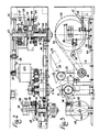
- Figure 1 is a diagrammatic, side elevational view of the primary means forming the apparatus according to the invention.
- Figures 2 and 3 respectively are a top plan view with parts in section, and a side elevational view of the kinematic motions for imparting an in-phase motion to the cam, by which the rotary blade means and the thin web-entraining roller pairs are caused to swing.
- Figure 4 is a plan view with parts in section, showing the upper pressure rollers in the thin web-entraining unit, and the rotary blade means.
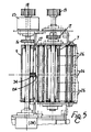
- Figure 5 is a plan view with parts in section, showing the lower rollers in the thin web-entraining unit, and the initial part of the belts for taking up and transferring under vacuum a cyclically cut web length.
- the lower rollers 5, 7 are smooth rollers and are, for example, made of aluminum, while the upper rollers 4, 6 are covered with rubber, are given a grooved configuration, and are supported at their ends by respective pairs of swingable supporting members 8, 9 which are fulcrumed respectively at 10, 11 about the machine frame, and are urged downward by the springs 12, 13 that are adjustable by means of screw/nut screw means 14, 15 (see also Figure 4).
- numerals 31, 131 thin web-ejecting fingers are designated, which are fitted into the annular recesses in rollers 4, 6, and are supported by the stationary crosspieces 32, 132.
- the upper rollers 4, 6 are kinematically connected to the respective lower roller 5, 7.
- the shafts of the lower rollers 5, 7 have one end protruding from the relative supporting member, and are provided with toothed equal pulleys 18, 19 for their connection through a toothed belt 20 to the output shaft of a speed variator 21.
- the roller 5 Downstream of pulley 15, the roller 5 is provided with an electromagnetic clutch 23, and at the opposite end thereof is provided with an electromagnetic brake 24 (Figure 5), so that the roller pair 4, 5 can be stopped when needed.
- Numeral 25 denotes an idler for belt 20 ( Figure 3).
- the kinematic chain 18-19-20 and/or the diameter of the roller pairs 4, 5 and 6, 7, are so provided that the downstream roller pair 6, 7 is rotated at a surface speed which is a little higher than the surface speed of the upstream roller pair 4, 5, so that the thin web length extending between the said roller pairs, will be longitudinally stretched to a proper degree.
- Perforated, equal endless belts 26 (Figure 1) are led over the lower roller 7, and these belts are set in a close relation, whereby a suction conveyor is formed. At their starting lower end the said belts 26 are led over an idler 27 by which the initial section of the said suction conveyor is arranged in a properly tapering down manner, between the said thin web-entraining roller pairs 4, and 6, 7.
- the suction conveyor is driven in motion by being set in contact with the pair of rollers 6, 7, and by the provision of any other kinematic connections, by which a linear velocity of the suction conveyor is ensured, that is the same as, or is slightly higher than the surface speed of the said pair of rollers 6, 7.
- numeral 28 are designated the channels in which the active upper branches of belts 26 are caused to slide, and to which suction is applied through the transversely arranged manifold 29.
- the thin web F being delivered from the first pair of rollers 4, 5 is caused to slide on a transversely arranged, stationary comb-like member 34, and the rotary blade means 60 to be disclosed later, for cutting with its blade the thin web F, which is set at a short distance therefrom, is caused to cooperate with the edge 134 of the said comb-like member 34 that performs the function of counterblade.
- the thin web F sinks on the inclined initial section of belts 26 and is then moved between the pair of rollers 6, 7, whereupon the thin web is carried by the straight upper branch of said belts 26.
- the variator 21 for transmission to the thin web-entraining roller pairs 4, 5 and 6, 7 of their motion of rotation is in its turn driven through the motion transmission drive consisting of the toothed pulleys 35, 36, the toothed belt 37, and the idler 38, by a crank member 39 keyed onto the shaft 40 of pulley 36.
- the crank member 39 the one end is fitted of a pivot pin 41 which is parallel to the said shaft 40, and which by its opposite end is made integral of a bushing 42 that is fitted on a straight guide 43 with its axis extending at right angles thereto, and that is slidable thereon.
- the guide 43 is by its ends rotatably supported by supporting members 44, 144 secured to a flat disc 45 that by one of its faces is in turn secured to a pinion 47, in an offset position relative to this pinion, and that is angularly adjustable in position by means of the slots 46 shown in Figure 1, the said pinion 47 transmitting to other components of the packaging machine their motion off rotation.
- the pinion 47 is keyed onto a shaft 48 rotatably supported by the machine frame, and by means of a further pinion 49 and a chain 50 with an idler 51, this pinion 47 is connected to a pair of pinions 52, 53 which are dowelled to a shaft 54 to be disclosed later, the pinion 53 being connected to a driving geared motor, not shown in the drawings.
- the above mentioned shaft 40 is rotatably supported by a slide 55 ( Figure 3) which is slidably mounted on a guide 56, and is connected to an adjusting screw 57, the whole arrangement being such that the said shaft 40 can be translated parallelly to itself, up to the each time required extent.
- the shaft 40 can be set in line with, or can be offset from the shaft 48 ( Figure 2), to the each time needed degree.
- the shafts 40, 48 are rotated at a same costant speed.
- the shaft 40 is rotated in a variable motion mode, so that the roller units 4, 5 and 6, 7, and the belts 26 are allowed to feed the thin web F to a to-be-packaged article, at first with a decelerated, and then with a suitably accelerated motion.
- the pulley 36 is shown in two different operative positions, respectively by a solid line and by a dash line.
- the motion adjustment means just described are not a feature particularly characterizing the invention, so that these means may be actually provided in any other suitable manner, or they may be even omitted.
- a shaft 58 is provided at a short distance therefrom and in parallel relation therewith, which by means of a pair of arms 59 rotatably supports the rotary blade means 60 that is arranged parallel to the said shaft 58, and is of the type comprising, for example, a shaft 160 on which a serrated blade 260 is longitudinally fitted.
- the shaft 160 is fitted at its one end with a toothed pulley 61 that by means of a toothed belt being kept stretched by jockey pulleys 62 carried by a stationary arm 63 secured to the shaft 58, is connected to a toothed pulley 64 keyed onto a bushing 65 being rotatably mounted on shaft 58.
- a tothed wheel 66 is keyed onto the bushing 65, and is caused to mesh with, or is indirectly connected to a respective toothed wheel 67 keyed onto the shaft 54 that is driven by the main geared motor of the machine.
- a cam 68 is keyed onto the said shaft 54 (see also Figures 2 and 3), and is caused to cooperate with the pin 69 provided at the free end of a lever 70, that by its opposite end is connected to the shaft 58.
- the operation of the thus conceived apparatus is simple and apparent.
- the blade means 60 is rotated at a suitable, preferably reduced speed, and the track of cam 68 is so provided as to promote the cyclical lifting and lowering of the said rotary blade means.
- the rotary blade means 60 is angularly moved into its down position, the blade thereof is caused to cooperate with the edge 134 of the underlying comb-like member or counterblade 34, whereby a cut will be made in the thin web F.
- the rotary blade means 60 is imparted its swinging motion at a frequency that is interlocked with the frequency at which a group of to-be-packaged articles is moved forward by the means for advancing these articles and for dealing out thereto the respective thin web length as obtained by successive thin web-cutting operations.
- cam track modified Only in exceptional cases it will become necessary to have the cam track modified. Of course, any other suitable means may be provided in place of the cam 68.
- the friction clutch 23 is set apart, and the brake 24 is operated and caused to stop the roller pair 4, 5, while the rollers 6, 7 and the conveyor 26 delivering the thin web length cut in the preceding cycle, are kept in motion.
Landscapes
- Engineering & Computer Science (AREA)
- Mechanical Engineering (AREA)
- Auxiliary Devices For And Details Of Packaging Control (AREA)
- Basic Packing Technique (AREA)
- Containers And Plastic Fillers For Packaging (AREA)
- Replacement Of Web Rolls (AREA)
- Advancing Webs (AREA)
- Treatment Of Fiber Materials (AREA)
- Perforating, Stamping-Out Or Severing By Means Other Than Cutting (AREA)
Abstract
Description
- The invention concernes an apparatus for cutting and feeding thin web lengths, which is provided particularly in a machine for packing articles into lengths of a heat-contractible thin web and showing the features of the preamble of
claim 1. - An apparatus of this kind is known from FR-A-1 469 856. In this appartus a continuous thin web is fed vertically by a pair of counter-rotating, parallel feed-rollers to a cutting device, comprising a revolving cutter and a cooperating, stationary counterblade. The revolving cutter shows a revolving support for a radial blade, whose axis of rotation is fixed relatively to the counterblade. At each revolution of the revolving support, the blade fastened thereon is brought in a position coacting with the counterblade. Thus a section of thin web that has passed between the said revolving cutter and stationary counterblade is cut from the continuous thin web.
- From the internal state of the art of the applicant, an appartus of the aforementioned kind is known, in which the revolving cutter is driven by a motor in an intermittent operative mode, comprising means, for example a friction clutch and a break, which are so provided that after the balde of the revolving cutter having caused to make a cut in the thin web, the said revolving cutter will be stopped in a position, in which the same does not interfere with the thin web, and in which it is ready for being again operated and moved into its motor-interlocked condition, so that the blade is caused to cut the successive thin web section.
- A similar apparatus is known also from US-A-30 15 978. In this apparatus, the revolving cutter is connected to spring means and is driven for a certain part of each revolution by impelling means, which accomplish a complete revolution at constant speed at each complete cycle of the machine, but as regards the control of the revolving cutter, they serve to load said spring means whilst for the remaining part of each revolution, which corresponds to an arc of a circle passing tangentially to the counterblade, the cutter is uncoupled from said constant speed revolving impelling means and moves rapidly under the influence of the said loaded spring means along said arc of a circle, so as to strike rapidly against the web passing over said counterblade, thus effecting a clean cut thereof and detaching from the continuous band a section of predetermined length. After this cutting action the said revolving cutter is brought by said spring means into a position in which it is again coupled to the said continuously revolving impelling means and the cycle is thus repeated.
- As a result of the above descibed intermittent operative mode of the cutting apparatus, the several components of the cutting apparatus are subjected to an anomalous stress, whereby their average life is much reduced, and considerable limits are set to their operation, the more so to their high speed operation.
- The invention aims to obviate the aforementioned inconvenients.
- The invention achieves this aim with an apparatus for cutting and feeding thin web lengths according to the preamble of
claim 1 which further comprises the features of the characterizing part ofclaim 1. - Further inventive features and improvements are delt with in the dependent subclaims.
- The lifting and lowering system carrying the revolving cutter causes this revolving cutter to make a cut in the thin web, when this revolving cutter is moved into its down position, while when no cutting in the thin web is to be made, the said revolving cutter is lifted and kept rotating at a suitable, preferably low speed. Down-stream of the cutting apparatus, the thin web is pulled forward by two pairs of rollers by which the thin web is kept stretched as required. The speed of rotation of said roller pairs can be changed so as to have the thin web pulled through the cutting apparatus by the needed amount each time, before the revolving cutter is lowered down against the counterblade and caused to make a cut in the thin web with the blade thereof. By modifying the angular speed or quite exceptionally, the frequency of the lifting and lowering motion, for example the cam track in a lifting and lowering system of a cam-controlled kind, the apparatus according to the invention is made capable to feed thin web sections of any desired length and at any speed. Also a possible variation in the speed of the thin web-entraining roller pairs is contemplated, which is achieved in such a manner that the said rollers will be imparted a variable motion, whith an initial deceleration and a successive acceleration, whereby to cause the thin web to be delicately slipped under a to-be-packaged article.
- The features of the invention and the advantages arising therefrom will clearly appear in the following specification of one preferred embodiment of the same, which is shown merely by way of a non-limiting example in the Figures of the three annexed sheets of drawing, in which:
- Figure 1 is a diagrammatic, side elevational view of the primary means forming the apparatus according to the invention.
- Figures 2 and 3 respectively are a top plan view with parts in section, and a side elevational view of the kinematic motions for imparting an in-phase motion to the cam, by which the rotary blade means and the thin web-entraining roller pairs are caused to swing.
- Figure 4 is a plan view with parts in section, showing the upper pressure rollers in the thin web-entraining unit, and the rotary blade means.
- Figure 5 is a plan view with parts in section, showing the lower rollers in the thin web-entraining unit, and the initial part of the belts for taking up and transferring under vacuum a cyclically cut web length.
- Referring first of all to Figure 1, there is shown that the thin web F being unwound from a not shown bobbin, after having being passed on the
rollers 1, 2, 3 and on thedevice 30 for neutralizing any electrostatic charges, is led between a first pair of superposedparallel rollers 4, 5, and then between a further pair of superposedparallel rollers 6, 7. In the saidroller pairs lower rollers 5, 7 are smooth rollers and are, for example, made of aluminum, while theupper rollers 4, 6 are covered with rubber, are given a grooved configuration, and are supported at their ends by respective pairs of swingable supportingmembers numerals rollers 4, 6, and are supported by thestationary crosspieces - Through
gears 16, 17 (see Figures 4 and 5), theupper rollers 4, 6 are kinematically connected to the respectivelower roller 5, 7. As shown in Figures 2, 5, the shafts of thelower rollers 5, 7 have one end protruding from the relative supporting member, and are provided with toothedequal pulleys 18, 19 for their connection through atoothed belt 20 to the output shaft of aspeed variator 21. Downstream ofpulley 15, theroller 5 is provided with anelectromagnetic clutch 23, and at the opposite end thereof is provided with an electromagnetic brake 24 (Figure 5), so that theroller pair 4, 5 can be stopped when needed. Numeral 25 denotes an idler for belt 20 (Figure 3). - The kinematic chain 18-19-20 and/or the diameter of the
roller pairs downstream roller pair 6, 7 is rotated at a surface speed which is a little higher than the surface speed of theupstream roller pair 4, 5, so that the thin web length extending between the said roller pairs, will be longitudinally stretched to a proper degree. Perforated, equal endless belts 26 (Figure 1) are led over the lower roller 7, and these belts are set in a close relation, whereby a suction conveyor is formed. At their starting lower end the saidbelts 26 are led over anidler 27 by which the initial section of the said suction conveyor is arranged in a properly tapering down manner, between the said thin web-entrainingroller pairs 4, and 6, 7. The suction conveyor is driven in motion by being set in contact with the pair ofrollers 6, 7, and by the provision of any other kinematic connections, by which a linear velocity of the suction conveyor is ensured, that is the same as, or is slightly higher than the surface speed of the said pair ofrollers 6, 7. In Figure 1, bynumeral 28 are designated the channels in which the active upper branches ofbelts 26 are caused to slide, and to which suction is applied through the transversely arrangedmanifold 29. - Still in Figure 1 there is shown that the thin web F being delivered from the first pair of
rollers 4, 5, is caused to slide on a transversely arranged, stationary comb-like member 34, and the rotary blade means 60 to be disclosed later, for cutting with its blade the thin web F, which is set at a short distance therefrom, is caused to cooperate with theedge 134 of the said comb-like member 34 that performs the function of counterblade. At the outlet of the comb-like member orcounterblade 34, the thin web F sinks on the inclined initial section ofbelts 26 and is then moved between the pair ofrollers 6, 7, whereupon the thin web is carried by the straight upper branch of saidbelts 26. - Referring to Figures 2 and 3, there is shown that the
variator 21 for transmission to the thin web-entrainingroller pairs toothed pulleys toothed belt 37, and theidler 38, by acrank member 39 keyed onto theshaft 40 ofpulley 36. In the saidcrank member 39 the one end is fitted of apivot pin 41 which is parallel to the saidshaft 40, and which by its opposite end is made integral of abushing 42 that is fitted on astraight guide 43 with its axis extending at right angles thereto, and that is slidable thereon. Theguide 43 is by its ends rotatably supported by supportingmembers 44, 144 secured to aflat disc 45 that by one of its faces is in turn secured to apinion 47, in an offset position relative to this pinion, and that is angularly adjustable in position by means of theslots 46 shown in Figure 1, the saidpinion 47 transmitting to other components of the packaging machine their motion off rotation. Thepinion 47 is keyed onto ashaft 48 rotatably supported by the machine frame, and by means of afurther pinion 49 and achain 50 with anidler 51, thispinion 47 is connected to a pair ofpinions 52, 53 which are dowelled to ashaft 54 to be disclosed later, the pinion 53 being connected to a driving geared motor, not shown in the drawings. - The above mentioned
shaft 40 is rotatably supported by a slide 55 (Figure 3) which is slidably mounted on aguide 56, and is connected to an adjustingscrew 57, the whole arrangement being such that the saidshaft 40 can be translated parallelly to itself, up to the each time required extent. - By means of the adjusting
screw 57, theshaft 40 can be set in line with, or can be offset from the shaft 48 (Figure 2), to the each time needed degree. When the twoshafts shaft 40 is offset from theshaft 48, theshaft 40 is rotated in a variable motion mode, so that theroller units belts 26 are allowed to feed the thin web F to a to-be-packaged article, at first with a decelerated, and then with a suitably accelerated motion. In Figure 3, thepulley 36 is shown in two different operative positions, respectively by a solid line and by a dash line. - The motion adjustment means just described are not a feature particularly characterizing the invention, so that these means may be actually provided in any other suitable manner, or they may be even omitted.
- In Figures 1 and 4 there appears that upstream of rollers 4, 5 a
shaft 58 is provided at a short distance therefrom and in parallel relation therewith, which by means of a pair ofarms 59 rotatably supports the rotary blade means 60 that is arranged parallel to thesaid shaft 58, and is of the type comprising, for example, ashaft 160 on which a serrated blade 260 is longitudinally fitted. Whenever the blade 260 is caused to act on the stretched thin web F being supported from its underside by the comb-like member 34 performing the function of counterblade, this blade will make a transverse cut in the thin web F. Theshaft 160 is fitted at its one end with a toothed pulley 61 that by means of a toothed belt being kept stretched byjockey pulleys 62 carried by astationary arm 63 secured to theshaft 58, is connected to atoothed pulley 64 keyed onto a bushing 65 being rotatably mounted onshaft 58. Atothed wheel 66 is keyed onto thebushing 65, and is caused to mesh with, or is indirectly connected to arespective toothed wheel 67 keyed onto theshaft 54 that is driven by the main geared motor of the machine. Acam 68 is keyed onto the said shaft 54 (see also Figures 2 and 3), and is caused to cooperate with thepin 69 provided at the free end of a lever 70, that by its opposite end is connected to theshaft 58. - The operation of the thus conceived apparatus is simple and apparent. The blade means 60 is rotated at a suitable, preferably reduced speed, and the track of
cam 68 is so provided as to promote the cyclical lifting and lowering of the said rotary blade means. When the rotary blade means 60 is angularly moved into its down position, the blade thereof is caused to cooperate with theedge 134 of the underlying comb-like member orcounterblade 34, whereby a cut will be made in the thin web F. The rotary blade means 60 is imparted its swinging motion at a frequency that is interlocked with the frequency at which a group of to-be-packaged articles is moved forward by the means for advancing these articles and for dealing out thereto the respective thin web length as obtained by successive thin web-cutting operations. In order to cause the length of the thin web sections to be changed, is it sufficient to have thevariator 21 so adjusted as to modify the speed of rotation of theroller pairs gear unit - Only in exceptional cases it will become necessary to have the cam track modified. Of course, any other suitable means may be provided in place of the
cam 68. - Should the supply of the to-be-packaged articles fail, the
friction clutch 23 is set apart, and thebrake 24 is operated and caused to stop theroller pair 4, 5, while therollers 6, 7 and theconveyor 26 delivering the thin web length cut in the preceding cycle, are kept in motion.
Claims (9)
- An apparatus for cutting and feeding lengths of a thin web (F), which is provided particularly in a machine for packing articles into lengths of a heat-contractible thin web, comprising:a) a revolving cutter (60) fitted with a serrated blade (260) and cooperating with a stationary counterblade (34) for cyclically cutting a continuous thin web (F) into sections of predetermined length;b) at least a pair of opposed feed-rollers (4, 5, 6, 7), for feeding the continuous thin web (F) between said revolving cutter (60) and said cooperating counterblade (34);
characterized in thatc) the feed path of the thin web (F) has an approximately horizontal orientation, between the revolving cutter (60) and the cooperating counterblade (34);d) the continuously revolving cutter (60) is mounted on means (58,59,68,69,70) allowing it to move up and down, from and to the stationary, cooperating counterblade (34);e) adjusting means are provided to ensure that the continuously revolving cutter (60) is lowered against the stationary counterblade (34) after a predetermined length of said thin web (F) has passed between the revolving cutter (60) and the cooperating counterblade, and in that said mounting means (58,59,68,69,70) (34) lift the cutter (60) from said counterblade (34) immediately after cutting.f) control means are provided to lower the continuously revolving cutter as soon as its blade (260) is going to arrive at the angular position for its cooperation with the counterblade (34). - The apparatus according to claim 1, characterized in that the angular velocity of the revolving cutter (60) is adjustable.
- The apparatus according to claims 1 or 2, characterized in that the frequency of the lowering and lifting of the revolving cutter (60) is adjustable.
- The apparatus according to one or more of the preceding claims, characterized in that the feeding velocity of the continuous thin web (F) between the revolving cutter (60) and the counterbalde (34) is adjustable.
- The apparatus according to one or more of the preceding claims, in which the revolving cutter (60) is carried by the one end of a pair of levers (59) pivotally connected to a shaft (58) arranged parallel to the said revolving cutter (60), with at least one lever (70) being connected by its one end to the said shaft (58), and which through a pin (69) provided at the opposite free end thereof, is caused to cooperate with a cam (68) being operated in an in-phase relation with the other component of the packing machine, and the said shaft (58) about which are fulcrumed the levers (59) that carry the revolving cutter (60), rotatably supports a part (61, 62, 63, 64, 65, 66) of a chain of the kinematic motions imparting the said revolving cutter (60) its motion of rotation.
- The apparatus according to claim 4, in which a gear unit (66, 67) is provided in the chain of the kinematic motions imparting the revovling cutter (60) its motion of rotation, and the said gear unit (66, 67) may be replaced, when needed, with another gear unit having a suitable gear ratio, any time the speed of rotation of said revolving cutter (60) has to be changed.
- The apparatus according to one or more of the preceding claims, in which a variator (21) is provided in the chain of the kinematic motions imparting the revolving cutter (60) its motion of rotation, whereby the speed of rotation of the said revolving cutter (60) is adjustable.
- The apparatus according to one or more of the preceding claims, in which the blade (260) of the revolving cutter (60) is caused to act on the thin web (F) between two pairs of driven parallel rollers (4, 5, 6, 7), by which the thin web (F) is longitudinally pulled in the manner as required for the thin web (F) to be unwound from a bobbin, and is longitudinally streched to a proper degree, provisions beeing made for the said roller pairs (4, 5; 6, 7) to be mutually synchronized and to be imparted their motion of rotation from a motive unit of the machine, with the interposition of a speed variator (21), the pair of rollers (4, 5) being connected to the kinematic motion driving the same, with the interposition of a friction clutch and brake unit (23, 24), whereby the said rollers can be uncoupled and braked, when needed, while the pair of rollers (6, 7) will deliver the thin web length having been cut during the preceding cycle.
- The apparatus according to one or more of the preceding claims, in which the speed variator (21) is connected to the actuating unit, whith the interposition of a variable motion-generating device (35 to 48), which is so adjustable that the thin web length being cyclically fed by the said apparatus, will be moved in a properly decelerated manner, and positioned at a to-be-packaged article.
Priority Applications (1)
| Application Number | Priority Date | Filing Date | Title |
|---|---|---|---|
| AT90112317T ATE97078T1 (en) | 1989-07-21 | 1990-06-28 | DEVICE FOR CUTTING AND FEEDING LENGTHS OF THIN FILM. |
Applications Claiming Priority (2)
| Application Number | Priority Date | Filing Date | Title |
|---|---|---|---|
| IT8912555A IT1232658B (en) | 1989-07-21 | 1989-07-21 | APPARATUS FOR CUTTING AND FEEDING OF FILM SECTIONS, PARTICULARLY IN THE MACHINES USED FOR THE PACKAGING OF PRODUCTS WITH HEAT-SHRINK FILM |
| IT1255589 | 1989-07-21 |
Publications (2)
| Publication Number | Publication Date |
|---|---|
| EP0408942A1 EP0408942A1 (en) | 1991-01-23 |
| EP0408942B1 true EP0408942B1 (en) | 1993-11-10 |
Family
ID=11141550
Family Applications (1)
| Application Number | Title | Priority Date | Filing Date |
|---|---|---|---|
| EP90112317A Expired - Lifetime EP0408942B1 (en) | 1989-07-21 | 1990-06-28 | Apparatus for cutting and feeding thin web lengths |
Country Status (5)
| Country | Link |
|---|---|
| EP (1) | EP0408942B1 (en) |
| AT (1) | ATE97078T1 (en) |
| DE (1) | DE69004509D1 (en) |
| ES (1) | ES2045660T3 (en) |
| IT (1) | IT1232658B (en) |
Family Cites Families (2)
| Publication number | Priority date | Publication date | Assignee | Title |
|---|---|---|---|---|
| DE1075037B (en) * | 1956-07-11 | 1960-02-04 | SASIB - SpA Scipione Innocenti Bologna (Italien) | Cutting device for separating pieces of certain length from a moving paper web or the like |
| FR1469856A (en) * | 1966-02-23 | 1967-02-17 | G D Sas Di Enzo Seragnoli Ed A | Device for feeding sheets of flexible material to a wrapping machine |
-
1989
- 1989-07-21 IT IT8912555A patent/IT1232658B/en active
-
1990
- 1990-06-28 AT AT90112317T patent/ATE97078T1/en active
- 1990-06-28 ES ES90112317T patent/ES2045660T3/en not_active Expired - Lifetime
- 1990-06-28 EP EP90112317A patent/EP0408942B1/en not_active Expired - Lifetime
- 1990-06-28 DE DE90112317T patent/DE69004509D1/en not_active Expired - Lifetime
Also Published As
| Publication number | Publication date |
|---|---|
| IT1232658B (en) | 1992-02-28 |
| ATE97078T1 (en) | 1993-11-15 |
| DE69004509D1 (en) | 1993-12-16 |
| IT8912555A0 (en) | 1989-07-21 |
| ES2045660T3 (en) | 1994-01-16 |
| EP0408942A1 (en) | 1991-01-23 |
Similar Documents
| Publication | Publication Date | Title |
|---|---|---|
| US4236708A (en) | Pneumatic sheet feeding apparatus | |
| US4029194A (en) | Automatic indexing and transferring apparatus | |
| EP2001772B1 (en) | Device for forming a continuous flow of oriented products | |
| EP0018457B1 (en) | Labelling equipment | |
| EP1803668B1 (en) | Feeder with adjustable time cycle and method | |
| US4470589A (en) | Method and apparatus for feeding and laminating sheets | |
| US6845861B2 (en) | Packet conveying assembly | |
| US4825622A (en) | Apparatus for selecting and feeding web material | |
| US4881357A (en) | Packaging machine for the continuous packaging of products having a variable size | |
| US20030010863A1 (en) | Core feeding method in a rewinding machine for making logs of sheet material | |
| US6964147B2 (en) | Operating method for a packaging machine of the “sleeve” type, packaging machine for implementing the said method, and package produced by the said method | |
| US6332527B1 (en) | Transport apparatus for handling cut products | |
| US6152002A (en) | Method and apparatus for trimming flat printed products along a predetermined cutting line | |
| US4683704A (en) | Method of and apparatus for wrapping | |
| JPH11310366A (en) | Signature carrying device for folding machine | |
| EP1500592B1 (en) | Apparatus for wrapping groups of products | |
| WO2003062108A2 (en) | Web speed metering apparatus and method | |
| EP0408942A1 (en) | Apparatus for cutting and feeding thin web lengths | |
| JP3786263B2 (en) | Sheet take-out device | |
| EP0491666B1 (en) | Film feeding and cutting group, applicable on automatic product conditioning machines | |
| US3300112A (en) | Machine for severing glass | |
| EP0830068A1 (en) | An indexer for moving food along a processing line in a precise manner | |
| WO2019077541A1 (en) | Film supplying apparatus for a wrapping machine | |
| US1963183A (en) | Feeding and slitting device | |
| US4334673A (en) | Delivery mechanism |
Legal Events
| Date | Code | Title | Description |
|---|---|---|---|
| PUAI | Public reference made under article 153(3) epc to a published international application that has entered the european phase |
Free format text: ORIGINAL CODE: 0009012 |
|
| AK | Designated contracting states |
Kind code of ref document: A1 Designated state(s): AT BE DE ES FR GB NL |
|
| 17P | Request for examination filed |
Effective date: 19910510 |
|
| 17Q | First examination report despatched |
Effective date: 19920511 |
|
| GRAA | (expected) grant |
Free format text: ORIGINAL CODE: 0009210 |
|
| AK | Designated contracting states |
Kind code of ref document: B1 Designated state(s): AT BE DE ES FR GB NL |
|
| PG25 | Lapsed in a contracting state [announced via postgrant information from national office to epo] |
Ref country code: NL Effective date: 19931110 Ref country code: DE Effective date: 19931110 Ref country code: BE Effective date: 19931110 Ref country code: AT Effective date: 19931110 |
|
| REF | Corresponds to: |
Ref document number: 97078 Country of ref document: AT Date of ref document: 19931115 Kind code of ref document: T |
|
| REF | Corresponds to: |
Ref document number: 69004509 Country of ref document: DE Date of ref document: 19931216 |
|
| ET | Fr: translation filed | ||
| REG | Reference to a national code |
Ref country code: ES Ref legal event code: FG2A Ref document number: 2045660 Country of ref document: ES Kind code of ref document: T3 |
|
| NLV1 | Nl: lapsed or annulled due to failure to fulfill the requirements of art. 29p and 29m of the patents act | ||
| PLBE | No opposition filed within time limit |
Free format text: ORIGINAL CODE: 0009261 |
|
| STAA | Information on the status of an ep patent application or granted ep patent |
Free format text: STATUS: NO OPPOSITION FILED WITHIN TIME LIMIT |
|
| 26N | No opposition filed | ||
| REG | Reference to a national code |
Ref country code: GB Ref legal event code: IF02 |
|
| PGFP | Annual fee paid to national office [announced via postgrant information from national office to epo] |
Ref country code: GB Payment date: 20040528 Year of fee payment: 15 |
|
| PGFP | Annual fee paid to national office [announced via postgrant information from national office to epo] |
Ref country code: ES Payment date: 20040603 Year of fee payment: 15 |
|
| PGFP | Annual fee paid to national office [announced via postgrant information from national office to epo] |
Ref country code: FR Payment date: 20040618 Year of fee payment: 15 |
|
| PG25 | Lapsed in a contracting state [announced via postgrant information from national office to epo] |
Ref country code: GB Free format text: LAPSE BECAUSE OF NON-PAYMENT OF DUE FEES Effective date: 20050628 |
|
| PG25 | Lapsed in a contracting state [announced via postgrant information from national office to epo] |
Ref country code: ES Free format text: LAPSE BECAUSE OF NON-PAYMENT OF DUE FEES Effective date: 20050629 |
|
| PG25 | Lapsed in a contracting state [announced via postgrant information from national office to epo] |
Ref country code: FR Free format text: LAPSE BECAUSE OF NON-PAYMENT OF DUE FEES Effective date: 20060228 |
|
| GBPC | Gb: european patent ceased through non-payment of renewal fee |
Effective date: 20050628 |
|
| REG | Reference to a national code |
Ref country code: FR Ref legal event code: ST Effective date: 20060228 |
|
| REG | Reference to a national code |
Ref country code: ES Ref legal event code: FD2A Effective date: 20050629 |