EP0407160B1 - A discharge tube arrangement - Google Patents
A discharge tube arrangement Download PDFInfo
- Publication number
- EP0407160B1 EP0407160B1 EP19900307289 EP90307289A EP0407160B1 EP 0407160 B1 EP0407160 B1 EP 0407160B1 EP 19900307289 EP19900307289 EP 19900307289 EP 90307289 A EP90307289 A EP 90307289A EP 0407160 B1 EP0407160 B1 EP 0407160B1
- Authority
- EP
- European Patent Office
- Prior art keywords
- discharge tube
- discharge
- arrangement
- fill
- visible light
- Prior art date
- Legal status (The legal status is an assumption and is not a legal conclusion. Google has not performed a legal analysis and makes no representation as to the accuracy of the status listed.)
- Expired - Lifetime
Links
Images
Classifications
-
- H—ELECTRICITY
- H01—ELECTRIC ELEMENTS
- H01J—ELECTRIC DISCHARGE TUBES OR DISCHARGE LAMPS
- H01J61/00—Gas-discharge or vapour-discharge lamps
- H01J61/02—Details
- H01J61/12—Selection of substances for gas fillings; Specified operating pressure or temperature
- H01J61/125—Selection of substances for gas fillings; Specified operating pressure or temperature having an halogenide as principal component
-
- H—ELECTRICITY
- H01—ELECTRIC ELEMENTS
- H01J—ELECTRIC DISCHARGE TUBES OR DISCHARGE LAMPS
- H01J65/00—Lamps without any electrode inside the vessel; Lamps with at least one main electrode outside the vessel
- H01J65/04—Lamps in which a gas filling is excited to luminesce by an external electromagnetic field or by external corpuscular radiation, e.g. for indicating plasma display panels
- H01J65/042—Lamps in which a gas filling is excited to luminesce by an external electromagnetic field or by external corpuscular radiation, e.g. for indicating plasma display panels by an external electromagnetic field
- H01J65/046—Lamps in which a gas filling is excited to luminesce by an external electromagnetic field or by external corpuscular radiation, e.g. for indicating plasma display panels by an external electromagnetic field the field being produced by using capacitive means around the vessel
Definitions
- This invention relates to a discharge tube arrangement and in particular to such an arrangement for use as a light source.
- the discharge tube could be a generic fluorescent lamp discharge tube containing a mix of inert gases and mercury vapour (e.g. argon gas and mercury vapour) and having on its inner surface a phosphor which converts 254nm U.V. radiation to visible light.
- the discharge tube could be a generic germicidal or curing lamp discharge tube constructed of quartz glass and containing a mix of inert gases and mercury vapour, but with no phosphor.
- the discharge is produced as a single turn loop forming the secondary of a transformer; the primary is formed by a coil, which may have a high permeability core. It has been found that low pressure metal halide discharges operated in this mode exhibit a wide range of instabilities and so are impractical as light sources.
- the discharge vessel is placed between the plates of a capacitor excited by a high frequency source.
- the current to sustain the discharge has to flow as displacement current through the glass or silica wall of the discharge vessel and so it is difficult to produce a discharge having a significant amount of power.
- the current increases with the frequency of excitation, so also does the dielectric loss due to the glass or silica wall, resulting in significant power losses in the wall of the discharge vessel.
- the inventors have surprisingly found that it is possible to achieve a stable, well-behaved, low pressure metal halide discharge in a discharge tube without electrodes by exciting the discharge using surface waves.
- the metal halide is at least partially dissociated and light is emitted in the visible region from both atomic and molecular fragments. It is envisaged that metal oxyhalides will exhibit a similar behaviour to metal halides.
- a discharge tube arrangement for generating visible light as exemplified in claim 1.
- a discharge tube arrangement provided in accordance with this aspect of the present invention can be used to generate visible light.
- the means for applying an r.f. electric field comprises an r.f. power generator and a launcher.
- the applying means can be arranged so as not to substantially obscure the discharge and the discharge itself can have a length of the order of centimetres to metres and a diameter of the order of millimetres to centimetres depending on the power used.
- a discharge tube arrangement comprises a discharge tube 20 mounted in a launcher 22.
- the discharge tube 20 is formed of a light-transmissive, dielectric material, such as glass, and contains a fill 24.
- the launcher 22 is made of an electrically conductive material, such as brass, and formed as a coaxial structure comprising an inner tube 26 and an outer tube 28.
- a first plate 30, at one end of the outer tube, provides a first end wall for the launcher structure.
- a second plate 31, integral with the outer tube 28, provides a second end wall.
- the inner tube 26 is shorter than the outer tube 28 and so positioned within the outer tube 28 as to define a first annular gap 32 and a second annular gap 33.
- Each of the first plate 30 and second plate 31 has an aperture for receiving the discharge tube 20.
- the outer tube 28, the first plate 30 and the second plate 31 form an unbroken electrically conductive path around, but not in electrical contact with, the inner tube 26 to provide an r.f. screening structure therearound.
- Suitable dimensions for the launcher of Figure 1 are as follows:
- the thickness of the electrically conductive material is of the order of millimetres, or less, depending on the construction method used.
- An r.f. power generator 34 (shown schematically) is electrically connected to the inner tube 26 of the launcher 22 via a coaxial cable 35 and an impedance matching network 36 (shown schematically as comprising capacitor 37 and inductor 38).
- the r.f. power generator 34, the impedance matching network 36, the coaxial cable 35 and the launcher 22 constitute an r.f. powered excitation device to energise the fill to produce a discharge.
- a body 40 of dielectric material inside the launcher 22 is provided as a structural element, to keep the size of the gaps 32, 33 constant and to hold the inner tube 26 in position.
- the body 40 also helps in shaping the electric field in the gaps 32, 33 for ease of starting or other purposes.
- Suitable dielectric materials which exhibit low loss at r.f. frequencies include glass, quartz and PTFE.
- the launcher may be partially or completely air filled, provided that means to support the inner tube are provided.
- an oscillating electric field having a frequency typically in the range of from 1MHz to 1GHz, is set up inside the launcher 22. At the first and second gaps 32, 33, this electric field is parallel to the longitudinal axis of the discharge tube 20. If sufficient power is applied, the consequent electric field produced in the fill 24 is sufficient to create a discharge through which an electromagnetic surface wave may be propagated in a similar manner to the arrangement of EP-A-0225753. Accordingly, the launcher 22 powered by the r.f. power generator 34 creates and sustains a discharge in the fill - the length and brightness of the discharge depending, inter alia, on the size of the discharge tube 20 and the power applied by the r.f. power generator 34. Such a discharge tube arrangement may therefore be used as a light source.
- the fill 24 may comprise a noble gas, such as argon, together with a compound selected from the group consisting of metal halides and metal oxyhalides. Mercury may also be added.
- a noble gas such as argon
- the inventors have tried a fill which contained the noble gas, argon (Ar), together with aluminium chloride (AlCl3). This was found to produce a stable discharge, emitting visible light, when excited by a surface wave.
- Halides of metals from the transition series of the periodic table can advantageously be used. These halides are sufficiently volatile to produce a vapour pressure at which a discharge can be generated at the wall operating temperatures of the discharge tube. They can be dissociated by electron impact. The resulting excited atoms, ions and molecules emit radiation; the metal atoms have large numbers of relatively low-lying energy levels giving rise to radiation throughout the visible region.
- Halides of neodymium (Nd) and other rare earth metals on excitation also give rise to radiation throughout the visible region. They are relatively involatile but can form complexes with other metal halides (known as complexing agents).
- the vapour pressure of the complex so formed can be factor of 105 greater than that of the rare earth metal halide.
- the complex should have a total vapour pressure exceeding about 10 ⁇ 3 torr at the operating temperature of the lamp, e.g. up to 250°C.
- complexing agents include the halides (ie chlorides, bromides or iodides - X is Cl, Br or I) of aluminium (AlX3), indium (InX3), gallium (GaX3), tin (SnX4), titanium (TiX4) as well as the compound di-iron (III) chloride (Fe2Cl6).
- halides ie chlorides, bromides or iodides - X is Cl, Br or I
- AlX3 aluminium
- InX3 indium
- GaX3 gallium
- tin (SnX4) titanium
- TiX4 titanium
- complexing agents include the halides (ie chlorides, bromides or iodides - X is Cl, Br or I) of aluminium (AlX3), indium (InX3), gallium (GaX3), tin (SnX4), titanium (TiX4) as well as the compound di-iron (III) chloride (Fe2
- the argon is used to increase overall vapour pressure and may be replaced by other noble gases, such as neon, helium or krypton.
- oxy-halides i.e. oxychlorides, oxybromides or oxyiodides - X is Cl, Br or I
- certain metals such as chromium (CrO2X2) and vanadium (VOX2 and VOX3), molybdenum (MoO2X2 and MoOX4), and tungsten (WO2X2 and WOX4)
- chromium CrO2X2
- VOX2 and VOX3 vanadium
- MoO2X2 and MoOX4 molybdenum
- WO2X2 and WOX4 tungsten
- Such oxy-halides are volatile liquids at room temperature.
Landscapes
- Physics & Mathematics (AREA)
- Electromagnetism (AREA)
- Engineering & Computer Science (AREA)
- Plasma & Fusion (AREA)
- Discharge Lamps And Accessories Thereof (AREA)
- Discharge Lamp (AREA)
- Vessels And Coating Films For Discharge Lamps (AREA)
Description
- This invention relates to a discharge tube arrangement and in particular to such an arrangement for use as a light source.
- It is known, e.g. as disclosed in EP-A-0225753 (University of California), to generate and sustain a low pressure discharge in a gas by using electromagnetic surface waves. Surface waves are created by an energizer (also known as a launcher) which is positioned around and external of, but not extending the whole length of, a discharge tube containing the gas. In such an arrangement, it is not necessary to provide electrodes inside the discharge tube. The power to generate the electromagnetic wave is provided by a radio frequency (r.f.) power generator.
- It is proposed that such an arrangement be used as a visible light or a UV source. To provide a visible light source, the discharge tube could be a generic fluorescent lamp discharge tube containing a mix of inert gases and mercury vapour (e.g. argon gas and mercury vapour) and having on its inner surface a phosphor which converts 254nm U.V. radiation to visible light. To provide a U.V. source, the discharge tube could be a generic germicidal or curing lamp discharge tube constructed of quartz glass and containing a mix of inert gases and mercury vapour, but with no phosphor.
- However, there is a disadvantage in the use of a fluorescent type discharge tube arrangement to produce visible light. As indicated hereinbefore, a discharge tube containing a mix of inert gases and mercury vapour radiates primarily in the U.V. so that a phosphor must be used to convert the U.V. to visible light. In this process about half the energy of the U.V. quantum is lost.
- It is theoretically possible to use a volatile metal halide to produce a low pressure discharge which emits visible light. Such metal halides are extremely reactive but their use in certain types of electrodeless discharge tube arrangements has been investigated.
- In the H-Discharge (also known as the 'inductively coupled discharge') arrangement, the discharge is produced as a single turn loop forming the secondary of a transformer; the primary is formed by a coil, which may have a high permeability core. It has been found that low pressure metal halide discharges operated in this mode exhibit a wide range of instabilities and so are impractical as light sources.
- In the E-discharge arrangement, the discharge vessel is placed between the plates of a capacitor excited by a high frequency source. However, the current to sustain the discharge has to flow as displacement current through the glass or silica wall of the discharge vessel and so it is difficult to produce a discharge having a significant amount of power. Though the current increases with the frequency of excitation, so also does the dielectric loss due to the glass or silica wall, resulting in significant power losses in the wall of the discharge vessel.
- Another type of electrodeless discharge is known as the 'ultra-high frequency' discharge. In such a discharge, the wavelength of the exciting source is shorter than or comparable with the discharge dimension. Such discharges have been investigated over many years but problems of power generation and geometry mean that they do not offer practical possibilities as commercially viable light sources.
- It has been found that discharges operated in these three prior art modes using a low pressure metal halide fill tend, under certain, ill-defined conditions, to form tentacles which attach themselves to the wall of the discharge vessel. This causes intense local hot spots and so failure of the light source. The discharges produced are also unstable and present a fluctuating load to the power generator leading to difficulties in matching. Furthermore, in the discharge arrangements used, the structure used to excite and sustain the discharge tends itself to obscure the discharge, reducing the amount of light that can reach the observer.
- It is an object of the present invention to provide a discharge tube arrangement for use as a source of light which at least alleviates the problems outlined hereinbefore.
- The inventors have surprisingly found that it is possible to achieve a stable, well-behaved, low pressure metal halide discharge in a discharge tube without electrodes by exciting the discharge using surface waves. The metal halide is at least partially dissociated and light is emitted in the visible region from both atomic and molecular fragments. It is envisaged that metal oxyhalides will exhibit a similar behaviour to metal halides.
- According to a first aspect of the present invention there is provided a discharge tube arrangement for generating visible light as exemplified in claim 1.
- A discharge tube arrangement provided in accordance with this aspect of the present invention can be used to generate visible light.
- Preferably the means for applying an r.f. electric field comprises an r.f. power generator and a launcher. Accordingly, the applying means can be arranged so as not to substantially obscure the discharge and the discharge itself can have a length of the order of centimetres to metres and a diameter of the order of millimetres to centimetres depending on the power used.
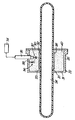
- Embodiments of the invention will now be described, by way of example only, and with reference to the accompanying drawing which shows a cross-sectional side view of a discharge tube arrangement provided in accordance with the present invention.
- As shown in Figure 1, a discharge tube arrangement comprises a
discharge tube 20 mounted in alauncher 22. Thedischarge tube 20 is formed of a light-transmissive, dielectric material, such as glass, and contains afill 24. - The
launcher 22 is made of an electrically conductive material, such as brass, and formed as a coaxial structure comprising aninner tube 26 and anouter tube 28. Afirst plate 30, at one end of the outer tube, provides a first end wall for the launcher structure. At the other end of theouter tube 28, asecond plate 31, integral with theouter tube 28, provides a second end wall. Theinner tube 26 is shorter than theouter tube 28 and so positioned within theouter tube 28 as to define a firstannular gap 32 and a secondannular gap 33. Each of thefirst plate 30 andsecond plate 31 has an aperture for receiving thedischarge tube 20. Theouter tube 28, thefirst plate 30 and thesecond plate 31 form an unbroken electrically conductive path around, but not in electrical contact with, theinner tube 26 to provide an r.f. screening structure therearound. - Suitable dimensions for the launcher of Figure 1 are as follows:

- The thickness of the electrically conductive material is of the order of millimetres, or less, depending on the construction method used.
- An r.f. power generator 34 (shown schematically) is electrically connected to the
inner tube 26 of thelauncher 22 via acoaxial cable 35 and an impedance matching network 36 (shown schematically as comprisingcapacitor 37 and inductor 38). The r.f. power generator 34, the impedance matchingnetwork 36, thecoaxial cable 35 and thelauncher 22 constitute an r.f. powered excitation device to energise the fill to produce a discharge. - A
body 40 of dielectric material inside thelauncher 22 is provided as a structural element, to keep the size of thegaps inner tube 26 in position. Thebody 40 also helps in shaping the electric field in thegaps - When the r.f. power supply 34 is switched on, an oscillating electric field, having a frequency typically in the range of from 1MHz to 1GHz, is set up inside the
launcher 22. At the first andsecond gaps discharge tube 20. If sufficient power is applied, the consequent electric field produced in thefill 24 is sufficient to create a discharge through which an electromagnetic surface wave may be propagated in a similar manner to the arrangement of EP-A-0225753. Accordingly, thelauncher 22 powered by the r.f. power generator 34 creates and sustains a discharge in the fill - the length and brightness of the discharge depending, inter alia, on the size of thedischarge tube 20 and the power applied by the r.f. power generator 34. Such a discharge tube arrangement may therefore be used as a light source. - In order to produce a discharge which emits visible light, the
fill 24 may comprise a noble gas, such as argon, together with a compound selected from the group consisting of metal halides and metal oxyhalides. Mercury may also be added. - The inventors have tried a fill which contained the noble gas, argon (Ar), together with aluminium chloride (AlCl₃). This was found to produce a stable discharge, emitting visible light, when excited by a surface wave.
- Halides of metals from the transition series of the periodic table, such as titanium, iron and niobium, can advantageously be used. These halides are sufficiently volatile to produce a vapour pressure at which a discharge can be generated at the wall operating temperatures of the discharge tube. They can be dissociated by electron impact. The resulting excited atoms, ions and molecules emit radiation; the metal atoms have large numbers of relatively low-lying energy levels giving rise to radiation throughout the visible region.
- Halides of neodymium (Nd) and other rare earth metals on excitation also give rise to radiation throughout the visible region. They are relatively involatile but can form complexes with other metal halides (known as complexing agents). The vapour pressure of the complex so formed can be factor of 10⁵ greater than that of the rare earth metal halide. The complex should have a total vapour pressure exceeding about 10⁻³ torr at the operating temperature of the lamp, e.g. up to 250°C. Examples of complexing agents include the halides (ie chlorides, bromides or iodides - X is Cl, Br or I) of aluminium (AlX₃), indium (InX₃), gallium (GaX₃), tin (SnX₄), titanium (TiX₄) as well as the compound di-iron (III) chloride (Fe₂Cl₆). Examples of complexes include NdAlCl₆ (a complex of NdCl₃ and AlCl₃) and NaAlCl₄ (a complex of NaCl and AlCl₃).
- The inventors envisage that stable discharges can be generated by surface waves from fills containing the following mixtures:
Tin (II) iodide (SnI₂) + sodium iodide (NaI) + AlCl₃ + Ar;
AlBr₃ + SnCl₂ + niobium (V) Chloride (NbCl₅) + Ar;
Indium (I) bromide (InBr) + AlCl₃ + Ar;
Thallium iodide (TlI) + AlCl₃ + Ar;
SnCl₂ + AlBr₃ + Ar;
Iron (II) iodide (FeI₂) + AlBr₃ + Ar;
TlI + NaI + FeI₂ + AlCl₃ + Ar;
NaI + AlBr₃ + Ar;
TlI + NaI + FeI₂ + AlBr₃ + Ar
InI + AlBr₃ - The argon is used to increase overall vapour pressure and may be replaced by other noble gases, such as neon, helium or krypton.
- It is further envisaged that the oxy-halides (i.e. oxychlorides, oxybromides or oxyiodides - X is Cl, Br or I) of certain metals, such as chromium (CrO₂X₂) and vanadium (VOX₂ and VOX₃), molybdenum (MoO₂X₂ and MoOX₄), and tungsten (WO₂X₂ and WOX₄) can be used in fills to produce visible light on excitation. Such oxy-halides are volatile liquids at room temperature.
Claims (4)
- A discharge tube arrangement for generating visible light, the arrangement comprising a low pressure discharge tube (23) having walls made of a light-transmissive dielectric material, and having means for applying a radio frequency (r.f.) electric field over a part of a wall of the discharge tube at a power sufficient to excite a surface wave in the fill, whereby, in use, the fill is excited to generate visible light, characterised in that the discharge tube contains a fill (24) comprising aluminium trichloride or aluminium tribromide together with an inert gas and at least one compound selected from the group consisting of metal halides and metal oxyhalides.
- An arrangement as claimed in claim 1, wherein said means for applying an r.f. electric field comprises an r.f. power generator and a launcher.
- An arrangement as claimed in claim 1 or 2, wherein said at least one compound comprises a halide of a transition metal.
- An arrangement as claimed in claim 1 or 2, wherein said at least one compound comprises a metal oxyhalide.
Applications Claiming Priority (2)
| Application Number | Priority Date | Filing Date | Title |
|---|---|---|---|
| GB898915611A GB8915611D0 (en) | 1989-07-07 | 1989-07-07 | A discharge tube arrangement |
| GB8915611 | 1989-07-07 |
Publications (3)
| Publication Number | Publication Date |
|---|---|
| EP0407160A2 EP0407160A2 (en) | 1991-01-09 |
| EP0407160A3 EP0407160A3 (en) | 1991-07-31 |
| EP0407160B1 true EP0407160B1 (en) | 1994-09-14 |
Family
ID=10659694
Family Applications (1)
| Application Number | Title | Priority Date | Filing Date |
|---|---|---|---|
| EP19900307289 Expired - Lifetime EP0407160B1 (en) | 1989-07-07 | 1990-07-04 | A discharge tube arrangement |
Country Status (4)
| Country | Link |
|---|---|
| EP (1) | EP0407160B1 (en) |
| JP (1) | JP2875860B2 (en) |
| DE (1) | DE69012460T2 (en) |
| GB (1) | GB8915611D0 (en) |
Cited By (1)
| Publication number | Priority date | Publication date | Assignee | Title |
|---|---|---|---|---|
| US7391154B2 (en) | 2002-09-11 | 2008-06-24 | Koninklijke Philips Electronics, N.V. | Low-pressure gas discharge lamp with gas filling containing tin |
Families Citing this family (7)
| Publication number | Priority date | Publication date | Assignee | Title |
|---|---|---|---|---|
| JPH03152852A (en) * | 1989-11-08 | 1991-06-28 | Matsushita Electric Works Ltd | Discharge lamp of high brightness and electrodeless discharge lamp device |
| JP2001127167A (en) * | 1999-10-28 | 2001-05-11 | Mitsumi Electric Co Ltd | Semiconductor device |
| JP2007507844A (en) * | 2003-09-30 | 2007-03-29 | コーニンクレッカ フィリップス エレクトロニクス エヌ ヴィ | Low pressure gas discharge lamp having means for immobilizing oxygen and moisture |
| US7847484B2 (en) | 2004-12-20 | 2010-12-07 | General Electric Company | Mercury-free and sodium-free compositions and radiation source incorporating same |
| US7825598B2 (en) | 2004-12-20 | 2010-11-02 | General Electric Company | Mercury-free discharge compositions and lamps incorporating Titanium, Zirconium, and Hafnium |
| EP1875488A2 (en) * | 2005-04-20 | 2008-01-09 | Philips Intellectual Property & Standards GmbH | Low-pressure gas discharge lamp comprising halides of indium and sodium |
| EP2020017A2 (en) * | 2006-05-15 | 2009-02-04 | Koninklijke Philips Electronics N.V. | Low-pressure gas discharge lamp having improved efficiency |
Family Cites Families (6)
| Publication number | Priority date | Publication date | Assignee | Title |
|---|---|---|---|---|
| US3720855A (en) * | 1972-02-28 | 1973-03-13 | Gte Laboratories Inc | Electric discharge lamp |
| US4480213A (en) * | 1982-07-26 | 1984-10-30 | Gte Laboratories Incorporated | Compact mercury-free fluorescent lamp |
| US4591759A (en) * | 1984-09-10 | 1986-05-27 | General Electric Company | Ingredients for solenoidal metal halide arc lamps |
| US4792725A (en) * | 1985-12-10 | 1988-12-20 | The United States Of America As Represented By The Department Of Energy | Instantaneous and efficient surface wave excitation of a low pressure gas or gases |
| GB8821671D0 (en) * | 1988-09-02 | 1988-10-19 | Emi Plc Thorn | Discharge tube arrangement |
| GB8920051D0 (en) * | 1989-09-05 | 1989-10-18 | Emi Plc Thorn | A discharge tube arrangement |
-
1989
- 1989-07-07 GB GB898915611A patent/GB8915611D0/en active Pending
-
1990
- 1990-07-04 DE DE1990612460 patent/DE69012460T2/en not_active Expired - Fee Related
- 1990-07-04 EP EP19900307289 patent/EP0407160B1/en not_active Expired - Lifetime
- 1990-07-06 JP JP2180368A patent/JP2875860B2/en not_active Expired - Lifetime
Cited By (1)
| Publication number | Priority date | Publication date | Assignee | Title |
|---|---|---|---|---|
| US7391154B2 (en) | 2002-09-11 | 2008-06-24 | Koninklijke Philips Electronics, N.V. | Low-pressure gas discharge lamp with gas filling containing tin |
Also Published As
| Publication number | Publication date |
|---|---|
| EP0407160A3 (en) | 1991-07-31 |
| EP0407160A2 (en) | 1991-01-09 |
| GB8915611D0 (en) | 1989-08-23 |
| DE69012460T2 (en) | 1995-05-11 |
| DE69012460D1 (en) | 1994-10-20 |
| JPH0367455A (en) | 1991-03-22 |
| JP2875860B2 (en) | 1999-03-31 |
Similar Documents
| Publication | Publication Date | Title |
|---|---|---|
| US5086258A (en) | Discharge tube arrangement | |
| US5834895A (en) | Visible lamp including selenium | |
| US4480213A (en) | Compact mercury-free fluorescent lamp | |
| US4492898A (en) | Mercury-free discharge lamp | |
| JPH0787093B2 (en) | High power radiator | |
| US4647821A (en) | Compact mercury-free fluorescent lamp | |
| US4427922A (en) | Electrodeless light source | |
| US4636692A (en) | Mercury-free discharge lamp | |
| US10453669B2 (en) | Electrodeless gas discharge lamps and methods of making the same | |
| EP0080799B1 (en) | Electrodeless light source | |
| EP0407160A2 (en) | A discharge tube arrangement | |
| US8421358B2 (en) | Lamp | |
| JP2003249196A (en) | Microwave electrodeless discharge lamp lighting device | |
| JPH0231458B2 (en) | ||
| JP2005538526A (en) | Low pressure gas discharge lamp with a gas filler containing tin | |
| CA2111426A1 (en) | Electrodeless lamp bulb | |
| US20120274207A1 (en) | Lamp | |
| CN101213636A (en) | Low-pressure discharge lamps including molecular radiators and additives | |
| US20070222389A1 (en) | Low Pressure Discharge Lamp Comprising a Discharge Maintaining Compound | |
| JP2007507843A (en) | Low pressure gas discharge lamp with a filling gas containing gallium | |
| US7944148B2 (en) | Mercury free tin halide compositions and radiation sources incorporating same | |
| WO2019234454A2 (en) | A plasma light source | |
| JP3178259B2 (en) | Electrodeless discharge lamp | |
| CN101124651A (en) | Low-pressure discharge lamps including metal halides | |
| CN112771644A (en) | Low metal halide dosage plasma light source |
Legal Events
| Date | Code | Title | Description |
|---|---|---|---|
| PUAI | Public reference made under article 153(3) epc to a published international application that has entered the european phase |
Free format text: ORIGINAL CODE: 0009012 |
|
| AK | Designated contracting states |
Kind code of ref document: A2 Designated state(s): AT BE CH DE DK ES FR GB GR IT LI LU NL SE |
|
| PUAL | Search report despatched |
Free format text: ORIGINAL CODE: 0009013 |
|
| AK | Designated contracting states |
Kind code of ref document: A3 Designated state(s): AT BE CH DE DK ES FR GB GR IT LI LU NL SE |
|
| 17P | Request for examination filed |
Effective date: 19910926 |
|
| RAP1 | Party data changed (applicant data changed or rights of an application transferred) |
Owner name: GE LIGHTING LIMITED |
|
| 17Q | First examination report despatched |
Effective date: 19931102 |
|
| RBV | Designated contracting states (corrected) |
Designated state(s): BE DE FR GB IT NL |
|
| GRAA | (expected) grant |
Free format text: ORIGINAL CODE: 0009210 |
|
| RIN1 | Information on inventor provided before grant (corrected) |
Inventor name: WHARMBY, DAVID OSBORN Inventor name: MUCKLEJOHN, STUART ALBERT Inventor name: GREB, ULRICH |
|
| AK | Designated contracting states |
Kind code of ref document: B1 Designated state(s): BE DE FR GB IT NL |
|
| ET | Fr: translation filed | ||
| REF | Corresponds to: |
Ref document number: 69012460 Country of ref document: DE Date of ref document: 19941020 |
|
| ITF | It: translation for a ep patent filed | ||
| PGFP | Annual fee paid to national office [announced via postgrant information from national office to epo] |
Ref country code: BE Payment date: 19950626 Year of fee payment: 6 |
|
| PGFP | Annual fee paid to national office [announced via postgrant information from national office to epo] |
Ref country code: NL Payment date: 19950627 Year of fee payment: 6 |
|
| PLBE | No opposition filed within time limit |
Free format text: ORIGINAL CODE: 0009261 |
|
| STAA | Information on the status of an ep patent application or granted ep patent |
Free format text: STATUS: NO OPPOSITION FILED WITHIN TIME LIMIT |
|
| 26N | No opposition filed | ||
| PG25 | Lapsed in a contracting state [announced via postgrant information from national office to epo] |
Ref country code: BE Effective date: 19960731 |
|
| BERE | Be: lapsed |
Owner name: GE LIGHTING LTD Effective date: 19960731 |
|
| PG25 | Lapsed in a contracting state [announced via postgrant information from national office to epo] |
Ref country code: NL Effective date: 19970201 |
|
| NLV4 | Nl: lapsed or anulled due to non-payment of the annual fee |
Effective date: 19970201 |
|
| PGFP | Annual fee paid to national office [announced via postgrant information from national office to epo] |
Ref country code: FR Payment date: 20010619 Year of fee payment: 12 |
|
| PGFP | Annual fee paid to national office [announced via postgrant information from national office to epo] |
Ref country code: DE Payment date: 20010620 Year of fee payment: 12 |
|
| PGFP | Annual fee paid to national office [announced via postgrant information from national office to epo] |
Ref country code: GB Payment date: 20010621 Year of fee payment: 12 |
|
| REG | Reference to a national code |
Ref country code: GB Ref legal event code: IF02 |
|
| PG25 | Lapsed in a contracting state [announced via postgrant information from national office to epo] |
Ref country code: GB Free format text: LAPSE BECAUSE OF NON-PAYMENT OF DUE FEES Effective date: 20020704 |
|
| PG25 | Lapsed in a contracting state [announced via postgrant information from national office to epo] |
Ref country code: DE Free format text: LAPSE BECAUSE OF NON-PAYMENT OF DUE FEES Effective date: 20030201 |
|
| GBPC | Gb: european patent ceased through non-payment of renewal fee |
Effective date: 20020704 |
|
| PG25 | Lapsed in a contracting state [announced via postgrant information from national office to epo] |
Ref country code: FR Free format text: LAPSE BECAUSE OF NON-PAYMENT OF DUE FEES Effective date: 20030331 |
|
| REG | Reference to a national code |
Ref country code: FR Ref legal event code: ST |
|
| PG25 | Lapsed in a contracting state [announced via postgrant information from national office to epo] |
Ref country code: IT Free format text: LAPSE BECAUSE OF NON-PAYMENT OF DUE FEES;WARNING: LAPSES OF ITALIAN PATENTS WITH EFFECTIVE DATE BEFORE 2007 MAY HAVE OCCURRED AT ANY TIME BEFORE 2007. THE CORRECT EFFECTIVE DATE MAY BE DIFFERENT FROM THE ONE RECORDED. Effective date: 20050704 |