EP0406348B1 - Coolant distribution pipes in a wet electrostatic separator - Google Patents
Coolant distribution pipes in a wet electrostatic separator Download PDFInfo
- Publication number
- EP0406348B1 EP0406348B1 EP89912147A EP89912147A EP0406348B1 EP 0406348 B1 EP0406348 B1 EP 0406348B1 EP 89912147 A EP89912147 A EP 89912147A EP 89912147 A EP89912147 A EP 89912147A EP 0406348 B1 EP0406348 B1 EP 0406348B1
- Authority
- EP
- European Patent Office
- Prior art keywords
- collector electrodes
- precipitator
- arrangement
- electrodes
- cooling
- Prior art date
- Legal status (The legal status is an assumption and is not a legal conclusion. Google has not performed a legal analysis and makes no representation as to the accuracy of the status listed.)
- Expired - Lifetime
Links
- 238000009826 distribution Methods 0.000 title claims abstract description 16
- 239000002826 coolant Substances 0.000 title abstract description 14
- 238000001816 cooling Methods 0.000 claims abstract description 30
- 239000012719 wet electrostatic precipitator Substances 0.000 claims abstract description 21
- 239000012716 precipitator Substances 0.000 claims abstract description 20
- 238000005260 corrosion Methods 0.000 claims abstract description 15
- 230000007797 corrosion Effects 0.000 claims abstract description 15
- 239000000428 dust Substances 0.000 claims abstract description 11
- 239000012717 electrostatic precipitator Substances 0.000 claims abstract description 9
- 238000009827 uniform distribution Methods 0.000 claims abstract 3
- 239000007789 gas Substances 0.000 claims description 24
- 239000000110 cooling liquid Substances 0.000 claims 1
- 229910000831 Steel Inorganic materials 0.000 abstract description 16
- 239000010959 steel Substances 0.000 abstract description 16
- 230000008901 benefit Effects 0.000 abstract description 7
- 229910045601 alloy Inorganic materials 0.000 abstract description 4
- 239000000956 alloy Substances 0.000 abstract description 4
- 230000015572 biosynthetic process Effects 0.000 abstract description 4
- 238000009833 condensation Methods 0.000 abstract description 4
- 230000005494 condensation Effects 0.000 abstract description 4
- 230000009467 reduction Effects 0.000 abstract description 2
- 239000003518 caustics Substances 0.000 abstract 1
- 238000010276 construction Methods 0.000 description 8
- 239000007788 liquid Substances 0.000 description 8
- QAOWNCQODCNURD-UHFFFAOYSA-N Sulfuric acid Chemical compound OS(O)(=O)=O QAOWNCQODCNURD-UHFFFAOYSA-N 0.000 description 6
- 239000000463 material Substances 0.000 description 6
- 235000011149 sulphuric acid Nutrition 0.000 description 6
- XLYOFNOQVPJJNP-UHFFFAOYSA-N water Substances O XLYOFNOQVPJJNP-UHFFFAOYSA-N 0.000 description 5
- 239000003546 flue gas Substances 0.000 description 4
- 238000000034 method Methods 0.000 description 4
- 239000002245 particle Substances 0.000 description 4
- 230000008569 process Effects 0.000 description 4
- 229920006395 saturated elastomer Polymers 0.000 description 4
- 239000000443 aerosol Substances 0.000 description 3
- 238000004519 manufacturing process Methods 0.000 description 3
- 239000004033 plastic Substances 0.000 description 3
- 229920003023 plastic Polymers 0.000 description 3
- 239000001117 sulphuric acid Substances 0.000 description 3
- 229910000851 Alloy steel Inorganic materials 0.000 description 2
- 239000002253 acid Substances 0.000 description 2
- 230000001419 dependent effect Effects 0.000 description 2
- 230000005684 electric field Effects 0.000 description 2
- 238000000926 separation method Methods 0.000 description 2
- UGFAIRIUMAVXCW-UHFFFAOYSA-N Carbon monoxide Chemical compound [O+]#[C-] UGFAIRIUMAVXCW-UHFFFAOYSA-N 0.000 description 1
- RYGMFSIKBFXOCR-UHFFFAOYSA-N Copper Chemical compound [Cu] RYGMFSIKBFXOCR-UHFFFAOYSA-N 0.000 description 1
- 238000003723 Smelting Methods 0.000 description 1
- 238000002485 combustion reaction Methods 0.000 description 1
- 229910052802 copper Inorganic materials 0.000 description 1
- 239000010949 copper Substances 0.000 description 1
- 230000003247 decreasing effect Effects 0.000 description 1
- 230000000694 effects Effects 0.000 description 1
- 239000011521 glass Substances 0.000 description 1
- 230000005660 hydrophilic surface Effects 0.000 description 1
- 230000002209 hydrophobic effect Effects 0.000 description 1
- 230000006872 improvement Effects 0.000 description 1
- 150000002500 ions Chemical class 0.000 description 1
- 239000002184 metal Substances 0.000 description 1
- 229910052751 metal Inorganic materials 0.000 description 1
- 230000004048 modification Effects 0.000 description 1
- 238000012986 modification Methods 0.000 description 1
- 230000002035 prolonged effect Effects 0.000 description 1
- 230000001846 repelling effect Effects 0.000 description 1
- 230000009291 secondary effect Effects 0.000 description 1
- 229910001220 stainless steel Inorganic materials 0.000 description 1
- 239000010935 stainless steel Substances 0.000 description 1
- 229910001256 stainless steel alloy Inorganic materials 0.000 description 1
- 238000011144 upstream manufacturing Methods 0.000 description 1
- 238000005406 washing Methods 0.000 description 1
- 239000002699 waste material Substances 0.000 description 1
Images


Classifications
-
- B—PERFORMING OPERATIONS; TRANSPORTING
- B03—SEPARATION OF SOLID MATERIALS USING LIQUIDS OR USING PNEUMATIC TABLES OR JIGS; MAGNETIC OR ELECTROSTATIC SEPARATION OF SOLID MATERIALS FROM SOLID MATERIALS OR FLUIDS; SEPARATION BY HIGH-VOLTAGE ELECTRIC FIELDS
- B03C—MAGNETIC OR ELECTROSTATIC SEPARATION OF SOLID MATERIALS FROM SOLID MATERIALS OR FLUIDS; SEPARATION BY HIGH-VOLTAGE ELECTRIC FIELDS
- B03C3/00—Separating dispersed particles from gases or vapour, e.g. air, by electrostatic effect
- B03C3/34—Constructional details or accessories or operation thereof
- B03C3/40—Electrode constructions
- B03C3/45—Collecting-electrodes
- B03C3/455—Collecting-electrodes specially adapted for heat exchange with the gas stream
Definitions
- the present invention relates to an improvement in wet electrostatic precipitators intended for cleansing moist and dust-laden gases and being of the kind which include a separator unit, a cooling condenser integrated with the separator unit, and emission electrodes which are disposed within a plurality of collector electrodes which extend through the cooling arrangement.
- Electrostatic precipitators are used, for instance, for cleansing dust-laden gases deriving, inter alia, from sulphuric-acid production processes, metal-smelting processes, and coal-combustion and waste combustion-plants.
- the electrostatic precipitator When the moist and dust-laden gases contain a given moisture content, the electrostatic precipitator will preferably have the form of a so-called wet electrostatic precipitator. Unfortunatley, the moisture-saturated gases cause corrosion problems.
- Steel exhibits clear advantages from a functional aspect. Steel constructions are wear resistant, dimensionally stable and can be readily inspected and examined. Furthermore, the material possesses good electrical properties and hydrophilic surface properties, i.e. properties which are directly decisive to the functional characteristics and performance of wet electrostatic precipitators, for instance.
- the object of the present invention is to provide a simple and useful arrangement by means of which cooling of the gases in the integrated cooling device in the wet electrostatic precipitator is effected uniformly.
- a further object is to provide an arrangement which will enable the use of high-alloy steel, particularly in structural elements subjected to a corrosive atmosphere, by reduction of the rate of corrosion, and/or an arrangement which will enable the use of a cheaper, steel of lower quality, i.e. steel having lower alloy contents. This object is achieved by the arrangement having the characteristic features set forth in the following claims.
- the inventive arrangement thus affords an important advantage of economic character, since the arrangement prolongs the technical life of the wet electrostatic precipitator when, for instance, the collector electrodes surrounding the emission electrodes and consisting, e.g., of tubular constructions are made from a certain, given alloyed steel.
- the inventive arrangement also provides another economic advantage, in that it is possible to select a low-alloyed steel for the manufacture of the collector electrodes and still achieve good corrosion resistance and a prolonged technical, useful life of the collector electrodes.
- the inventive arrangement also enables the effective cleansing of highly problematic flue gases which could not otherwise have been processed in a steel construction without needing to use, for instance, lead or plastic constructions with associated drawbacks.
- Figure 1 is a partially transparent, perspective view of an electrostatic precipitator intended for cleansing moist gases, i.e. a so-called wet electrostatic precipitator having a condensing cooling arrangement integrated therewith;
- Figure 2 is a schematic, longitudinal sectional view of a wet electrostatic precipitator provided with the inventive arrangement;
- Figure 3 is a sectional view of the arrangement shown in Figure 2 taken on the line III-III in said figure;
- Figure 4 is a sectional view of the arrangement shown in Figure 2, taken on the line IV-IV in said figure;
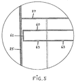
- Figure 5 is an enlarged view of the section V referenced in Figure 2.
- FIG. 1 illustrates an electrostatic precipitator in the form of a wet electrostatic precipitator equipped with an integrated condensing cooling arrangement.
- the illustrated wet electrostatic precipitator 1 includes a high-voltage source 2 and isolators 3 which carry a plurality of emission electrodes 4, via a framework construction. Each emission electrodes 4 is surrounded by a collector electrode 5, suitably of tubular construction.
- the voltage source 2 is operative to create a potential difference between the emission electrodes 4 and the surrounding collector electrodes 5, such as to generate an electric field in a region 6 between said electrodes.
- the moisture and dust laden gas flows through the region 6 and the dust and moisture particles are so influenced by the electric field that they deposit primarily on the inner surfaces of the collector electrodes 5, i.e.
- the moisture and dust laden gas flows up through the tubular collector electrodes 5, and the potential difference, preferably in the form of a d.c. voltage, created between the collector electrodes 5 and the emission electrodes 4 results in a glow and a corona discharge, therewith exerting the maximum separation on the individual moisture and dust particles carried by the gas and therewith the maximum possible gas cleansing effect, the particles of moisture and dust being collected essentially on the inner surfaces of the tubes 5 and falling downwards from the precipitator 1 in the direction of the arrow 10.
- the precipitator unit or separation unit 20 of the wet electrostatic precipitator 1 includes a condensing cooler arrangement 21 which has an inlet 22 for cooling medium 23, said cooling medium being a liquid coolant, for instance water.
- the cooling arrangement 21 also includes a cooling-medium outlet 24.
- the cooling arrangement 21 is defined externally by metal shell-plates 25, a bottom plate 26 and a top plate 27.
- the bottom plate 26 and the top plate 27 are provided with holes for accommodating the tubular collector electrodes 5 and a connection which will ensure against leakage of cooling medium, e.g. a welded connection, is provided between the tubes 5 and the plates 26 and 27.
- the circulating cooling medium 23 fills the space defined between the outer surfaces of the tubes 5 and the outer casing of the cooler, said outer casing being formed by the shell plates 25, the bottom plate 26 and the top plate 27.
- Draw rods 30 are preferably disposed between the sheel plates 25, for reasons of mechanical strength.
- the inventive precipitator unit 20 thus includes the collector electrodes 5, the emission electrodes 4, located centrally in and coaxially with said collector electrodes, and the condensing cooling arrangement 21.
- tubular collector electrodes 5 Because, inter alia, acid and ion-containing aerosols present in the flue gases are deposited within the tubular collector electrodes 5, it is often necessary to construct the tubular collector electrodes from an expensive, high-alloy steel or from a still more corrosion-resistant material, resulting in relatively high costs with respect to the wet electrostatic precipitator 1.
- the aforesaid external cooling of the tubes 5 will thus lower the temperature of the tubes and enhance condensation on the inner surfaces of the tubes. This enables the rate at which the tubes 5 are corroded as a result of the corrosion-promoting layers of condensation forming on the inner surfaces of the tubes to be reduced.
- a special arrangement is provided in accordance with the invention for the purpose of achieving uniform cooling of all tubular collector electrodes 5.
- the inventive arrangement enables all tubes 5, which enclose electrodes in the precipitator 20, to be coooled uniformly. This is achieved by providing means in the form, e.g., of a plurality of distributing pipes 50 and 60 in both the upper and the lower end parts of the precipitator unit 20.
- the inlet distribution pipes 50 are disposed in the lower, end-part of the precipitator unit 20 and are preferably connected in parallel so that the cooling medium entering the inlet 22 is distributed in parallel to all inlet distribution pipes 50, via a distribution channel 51.
- the inlet distribution pipes 50 are closed or sealed at their free ends 52 and are provided along their upper surfaces with a plurality of cooling-medium outlet holes 53.
- the outlet distribution pipes 60 are shown in Figure 3.
- the free ends 62 of the pipes 60 are closed or sealed and a plurality of inlet holes 63 are distributed along the bottom surface of respective pipes.
- the outlet distribution pipes 60 communicate with a channel 61, which in turn communicates with the cooling-medium outlet 24.
- inlet 22 and the outlet 24 communicate with an external cooling circuit in a manner to recover the thermal energy taken-up from the collector electrodes 5, this recovered energy being used for some useful purpose.
- the distribution pipes 50 and 60 may vary in number and the dimensions of the holes 53 and 63 can vary along the length of respective pipes in a manner to compensate for the pressure drop occurring in the pipes and so that liquid will enter and exit uniformly along the whole length of the pipes.
- the closed or sealed ends 52 and 62 of respective pipes 50 and 60 can be fixated relative to their surroundings.
- holes or openings 53 and 63, disposed in the distribution pipes 50 and 60 may be directed in mutually different directions, such as to achieve optimum distribution of coolant in the cooling arrangement 21.
- the improved uniformity in distribution of the cooling medium achieved in accordance with the present invention will also result, as a secondary effect, in an improved energy yield.
- the inventive arrangement thus provides a particularly effective and uniform cooling of all collector electrodes 5 which, in accordance with the aforegoing, results substantially in a lower corrosion rate in respect of the collector electrodes, as a result of the condensation formed on the inner surfaces of said electrodes.
- the useful life of the wet electrostatic precipitator can be increased and/or the collector electrodes can be made of a less expensive steel having a lower alloy content than was previously possible.
- the exterior shell-plates 25 of the cooling arrangement 21 may be made of non-alloyed steel plate.
- the aerosol droplets formed, for instance, in an upstream washing tower and entering the downstream wet electrostatic precipitator often have very high concentrations of, e.g., H2SO4.
- the amount of liquid/H2SO4 in the aerosol is small. Let us assume that it can amount to 1 g/Nm3.
- water vapour condenses onto the cooling surfaces/walls of the filter units.
- the amount of water vapour thus precipitated will normally lie between 500-1,500 l/h.
- the gas has a saturation temperature of 60°C and that 1,000 litres of gas are cooled each hour.
- the precipitator unit 10 In those instances when, for instances, it is preferred to configure the precipitator unit 10 with circular outer contours or cross-sectional shape, such that the shell plates 25 of the cooling arrangement 21 are, in principle, replaced by a relatively large tube, it is preferred that at least certain of the distribution pipes 50, 60 are given a curvature adapted to the circular contour aforementioned.
Landscapes
- Electrostatic Separation (AREA)
Abstract
Description
- The present invention relates to an improvement in wet electrostatic precipitators intended for cleansing moist and dust-laden gases and being of the kind which include a separator unit, a cooling condenser integrated with the separator unit, and emission electrodes which are disposed within a plurality of collector electrodes which extend through the cooling arrangement.
- Electrostatic precipitators are used, for instance, for cleansing dust-laden gases deriving, inter alia, from sulphuric-acid production processes, metal-smelting processes, and coal-combustion and waste combustion-plants.
- When the moist and dust-laden gases contain a given moisture content, the electrostatic precipitator will preferably have the form of a so-called wet electrostatic precipitator. Unfortunatley, the moisture-saturated gases cause corrosion problems.
- In the case of wet electrostatic precipitators which are intended, for instance, for treating moisture-saturated process gases and flue gases which contain Cl⁻, F⁻, SO₂, SO₃, etc. and other highly corrosive components, it has hitherto been necessary to manufacture in particular those components and parts of the precipitator subjected to corrosion attack from lead or plastics material. These materials have been found satisfactory from the aspect of corrosion in many instances, although they have, unfortunately, obvious limitations or, in many instances, have been highly unsuitable with respect to the fulfillment of other properties and characteristics which determine the function of the precipitator. The formation of cracks is one example of the problems which result from the use of lead and pastics material, although other problems also arise. Another example is that the surface of precipitator parts made from a plastic material are water repelling (hydrophobic), which prevents the formation of a uniformly dispersed liquid film on, for instance, the collector electrodes.
- Steel exhibits clear advantages from a functional aspect. Steel constructions are wear resistant, dimensionally stable and can be readily inspected and examined. Furthermore, the material possesses good electrical properties and hydrophilic surface properties, i.e. properties which are directly decisive to the functional characteristics and performance of wet electrostatic precipitators, for instance.
- The use of a highly-alloyed, stainless steel in, for instance, wet electrostatic precipitators is limited by the extent to which the steel can withstand the troublesome operating environment generated by moisture-saturated gas and elevated temperatures, without becoming corroded too quickly. Improved resistance to corrosion can be achieved by selecting certain stainless steel-alloys of high alloy contents. However, such high-alloyed steels are also subjected to corrosion, and in many cases to an unacceptably high degree of corrosion, when the temperature of the saturated gas begins to exceed, e.g., 40-60°C.
- In order to provide an improved corrosive environment for steel, it is particularly suitable to integrate a condensing cooling device in the actual precipitator unit of the electrostatic precipitator. The provision of a separate device for cooling the flue gas prior to said gas enterring the separator unit of the electrostatic precipitator constitutes a considerably more expensive solution from an economic point of view.
- Wet electrostatic filters having integrated condensing cooling devices have been known for a long time. GB-B-136464 and FR-A-727090 disclose the oldest devices simply designed for air-cooling to obtain condensing conditions. Water-cooled devices are disclosed in DE-B-1013622 and FR-A-944548, whereby the former suggests an extruded construction of lead or copper comprising both cooling tubes and collecting electrodes and the latter one cooling jacket which surrounds all the collecting electrodes. In DE-B-2743292 the corrosion problems are solved by the use of collector surfaces made of glass or hard PVC. DE-A-2340350 suggests an air inblow in the lower part of the condensing chamber outside and around the collecting electrodes in order to avoid formation of crust of dust inside the same. The air is then lead out through openings around the upper part of the outer wall of the condensing chamber.
- Unfortunately, serious corrosion problems are also experienced in connection with wet electrostatic filters having integrated condensing cooling devices, since, as a result of varying degrees of uneveness in cooling of the hot gasses, the inner surface of the collecting electrodes which surround the emmission electrodes and which may have the form, e.g., of hollow tubes, take-up the liquid condensing from the moisture-laden gas to be cleansed in the electrostatic precipitator.
- The object of the present invention is to provide a simple and useful arrangement by means of which cooling of the gases in the integrated cooling device in the wet electrostatic precipitator is effected uniformly. A further object is to provide an arrangement which will enable the use of high-alloy steel, particularly in structural elements subjected to a corrosive atmosphere, by reduction of the rate of corrosion, and/or an arrangement which will enable the use of a cheaper, steel of lower quality, i.e. steel having lower alloy contents. This object is achieved by the arrangement having the characteristic features set forth in the following claims.
- The inventive arrangement thus affords an important advantage of economic character, since the arrangement prolongs the technical life of the wet electrostatic precipitator when, for instance, the collector electrodes surrounding the emission electrodes and consisting, e.g., of tubular constructions are made from a certain, given alloyed steel. The inventive arrangement also provides another economic advantage, in that it is possible to select a low-alloyed steel for the manufacture of the collector electrodes and still achieve good corrosion resistance and a prolonged technical, useful life of the collector electrodes. The inventive arrangement also enables the effective cleansing of highly problematic flue gases which could not otherwise have been processed in a steel construction without needing to use, for instance, lead or plastic constructions with associated drawbacks.
- The invention will now be described in more detail with reference to exemplifying embodiments thereof illustrated in the accompanying drawings, in which Figure 1 is a partially transparent, perspective view of an electrostatic precipitator intended for cleansing moist gases, i.e. a so-called wet electrostatic precipitator having a condensing cooling arrangement integrated therewith;
Figure 2 is a schematic, longitudinal sectional view of a wet electrostatic precipitator provided with the inventive arrangement; Figure 3 is a sectional view of the arrangement shown in Figure 2 taken on the line III-III in said figure; Figure 4 is a sectional view of the arrangement shown in Figure 2, taken on the line IV-IV in said figure; and Figure 5 is an enlarged view of the section V referenced in Figure 2. - Figure 1 illustrates an electrostatic precipitator in the form of a wet electrostatic precipitator equipped with an integrated condensing cooling arrangement. The illustrated wet electrostatic precipitator 1 includes a high-
voltage source 2 andisolators 3 which carry a plurality ofemission electrodes 4, via a framework construction. Eachemission electrodes 4 is surrounded by acollector electrode 5, suitably of tubular construction. Thevoltage source 2 is operative to create a potential difference between theemission electrodes 4 and the surroundingcollector electrodes 5, such as to generate an electric field in aregion 6 between said electrodes. The moisture and dust laden gas flows through theregion 6 and the dust and moisture particles are so influenced by the electric field that they deposit primarily on the inner surfaces of thecollector electrodes 5, i.e. the inner surfaces of the tubes, so that the gas is essentially cleansed from moisture and dust particles when exiting from the dust precipitator. The flow of moisture and dust laden gas into the wet electrostatic precipitator 1 is symbolized by thearrow 8, whereas the cleansed gas exiting from the precipitator 1 is symbolized by the arrow 9. - As previously mentioned, the moisture and dust laden gas flows up through the
tubular collector electrodes 5, and the potential difference, preferably in the form of a d.c. voltage, created between thecollector electrodes 5 and theemission electrodes 4 results in a glow and a corona discharge, therewith exerting the maximum separation on the individual moisture and dust particles carried by the gas and therewith the maximum possible gas cleansing effect, the particles of moisture and dust being collected essentially on the inner surfaces of thetubes 5 and falling downwards from the precipitator 1 in the direction of thearrow 10. - When applicable, the components of the Figure 2 illustration have been identified with the same references as those used in Figure 1.
- In accordance with the present invention, the precipitator unit or
separation unit 20 of the wet electrostatic precipitator 1 includes acondensing cooler arrangement 21 which has aninlet 22 forcooling medium 23, said cooling medium being a liquid coolant, for instance water. Thecooling arrangement 21 also includes a cooling-medium outlet 24. Thecooling arrangement 21 is defined externally by metal shell-plates 25, abottom plate 26 and atop plate 27. Thebottom plate 26 and thetop plate 27 are provided with holes for accommodating thetubular collector electrodes 5 and a connection which will ensure against leakage of cooling medium, e.g. a welded connection, is provided between thetubes 5 and theplates cooling medium 23 fills the space defined between the outer surfaces of thetubes 5 and the outer casing of the cooler, said outer casing being formed by theshell plates 25, thebottom plate 26 and thetop plate 27. -
Draw rods 30 are preferably disposed between thesheel plates 25, for reasons of mechanical strength. - The
inventive precipitator unit 20 thus includes thecollector electrodes 5, theemission electrodes 4, located centrally in and coaxially with said collector electrodes, and thecondensing cooling arrangement 21. - Because, inter alia, acid and ion-containing aerosols present in the flue gases are deposited within the
tubular collector electrodes 5, it is often necessary to construct the tubular collector electrodes from an expensive, high-alloy steel or from a still more corrosion-resistant material, resulting in relatively high costs with respect to the wet electrostatic precipitator 1. The aforesaid external cooling of thetubes 5 will thus lower the temperature of the tubes and enhance condensation on the inner surfaces of the tubes. This enables the rate at which thetubes 5 are corroded as a result of the corrosion-promoting layers of condensation forming on the inner surfaces of the tubes to be reduced. A special arrangement is provided in accordance with the invention for the purpose of achieving uniform cooling of alltubular collector electrodes 5. The inventive arrangement enables alltubes 5, which enclose electrodes in theprecipitator 20, to be coooled uniformly. This is achieved by providing means in the form, e.g., of a plurality of distributingpipes precipitator unit 20. - It will be understood that the number of distributing
pipes collector electrodes 5, and in the case of the exemplifying embodiments, illustrated in Figures 2-5, three such distributing pipes are provided in both the upper and the lower end parts of the precipitator unit. - As will be seen from Figure 4, the
inlet distribution pipes 50 are disposed in the lower, end-part of theprecipitator unit 20 and are preferably connected in parallel so that the cooling medium entering theinlet 22 is distributed in parallel to allinlet distribution pipes 50, via adistribution channel 51. Theinlet distribution pipes 50 are closed or sealed at theirfree ends 52 and are provided along their upper surfaces with a plurality of cooling-medium outlet holes 53. - The
outlet distribution pipes 60 are shown in Figure 3. Thefree ends 62 of thepipes 60 are closed or sealed and a plurality ofinlet holes 63 are distributed along the bottom surface of respective pipes. Theoutlet distribution pipes 60 communicate with achannel 61, which in turn communicates with the cooling-medium outlet 24. - It will be understood that the
inlet 22 and theoutlet 24 communicate with an external cooling circuit in a manner to recover the thermal energy taken-up from thecollector electrodes 5, this recovered energy being used for some useful purpose. - It will be seen from the enlarged view of Figure 5 that the distributing
tubes 60 are closed or sealed at their oneend 62. This applies, of course, to both theinlet distributing pipes 50 and theoutlet distributing pipes 60. - As will be understood, the
distribution pipes holes ends respective pipes - A particular advantage is afforded when the
liquid inlet 22 is located in the lower part of the precipitator unit and theliquid outlet 24 is located in the upper part of said unit, since co-action is then achieved with the thermal medium movement. It will be understood, however, that it lies within the scope of the invention to switch the locations of theinlet 22 and theoutlet 24. - It will also be understood that the holes or
openings distribution pipes cooling arrangement 21. - The improved uniformity in distribution of the cooling medium achieved in accordance with the present invention will also result, as a secondary effect, in an improved energy yield.
- The inventive arrangement thus provides a particularly effective and uniform cooling of all
collector electrodes 5 which, in accordance with the aforegoing, results substantially in a lower corrosion rate in respect of the collector electrodes, as a result of the condensation formed on the inner surfaces of said electrodes. In conjunction herewith, the useful life of the wet electrostatic precipitator can be increased and/or the collector electrodes can be made of a less expensive steel having a lower alloy content than was previously possible. - For example, the exterior shell-
plates 25 of thecooling arrangement 21 may be made of non-alloyed steel plate. - The following non-limitive examples can be mentioned to further illustrate the advantages afforded by the present invention:
The aerosol droplets formed, for instance, in an upstream washing tower and entering the downstream wet electrostatic precipitator often have very high concentrations of, e.g., H₂SO₄. - On the other hand, the amount of liquid/H₂SO₄ in the aerosol is small. Let us assume that it can amount to 1 g/Nm³.
- Assume that a wet electrostatic precipitator processes about 20,000 Nm³ of gas per hour. This implies 20,000 x 0.001 = 20 kg liquid containing, let us say, 35% H₂SO₄ which is deposited on the inner surfaces of the tubular collector electrodes per hour.
- When the gas cools, water vapour condenses onto the cooling surfaces/walls of the filter units. The amount of water vapour thus precipitated will normally lie between 500-1,500 l/h.
- Assume that the gas has a saturation temperature of 60°C and that 1,000 litres of gas are cooled each hour.
- The sulphuric acid (20 kg x 0.35 = 7.0 kg) will then be diluted with a further 1,000 litres of water.
- The actual sulphuric-acid concentration will thus fall from

This cooling/condensing process will mean that the new operating point for the steel in the collector electrodes will be moved, partly due to the low temperature of the steel and partly because of the radically changed acid concentration, therewith decreasing the corrosion rate of the steel. - It will be understood from the above description that the means provided in accordance with the invention for effecting uniform and efficient cooling of the collector electrodes afford very important advantages, and that the structural configuration of said means can be readily adapted to the construction of the precipitator unit and that said means are thus not dependent on the number of collector electrodes present or their form and configuration.
- In those instances when, for instances, it is preferred to configure the
precipitator unit 10 with circular outer contours or cross-sectional shape, such that theshell plates 25 of thecooling arrangement 21 are, in principle, replaced by a relatively large tube, it is preferred that at least certain of thedistribution pipes - The invention is thus not restricted to the illustrated and described embodiments, since changes and modifications can be made within the scope of the following claims.
Claims (3)
- An arrangement in a wet electrostatic precipitator (1) for cleansing moisture and dust laden gases, said wet electrostatic precipitator (1) including a condensing cooler arrangement (21) integrated with the precipitator unit (20) of said electrostatic precipitator, and in which emission electrodes (4) are disposed within a plurality of collector electrodes (5) which extend through the cooling arrangement (21), and in which the gas flows forwardly through the collector electrodes (5), characterized in that distribution pipes (50, 60) are disposed in both the upper and the lower end parts of the precipitator unit (20) in a region between the collector electrodes (5), the inner surfaces of which being exposed for highly corrosive components during operation, such as to provide uniform distribution of cooling liquid along the outer surfaces of the collector electrodes, whereby the rate of corrosion on the inner surfaces of the collector electrodes is substantially reduced.
- An arrangement according to Claim 1, characterized in that the distribution pipes (50, 60) are provided with a plurality of openings (53 and 63 respectively) along their lengths.
- An arrangement according to Claim 1 or 2, characterized in that the distribution pipes (50, 60) are closed or sealed at their respective one ends (52 and 62 respectively).
Priority Applications (1)
| Application Number | Priority Date | Filing Date | Title |
|---|---|---|---|
| AT89912147T ATE99994T1 (en) | 1988-11-04 | 1989-11-02 | ARRANGEMENT OF COOLANT DISTRIBUTION PIPES IN A WET ELECTROSTATIC DUST COLLECTOR. |
Applications Claiming Priority (2)
| Application Number | Priority Date | Filing Date | Title |
|---|---|---|---|
| SE8804008A SE462421B (en) | 1988-11-04 | 1988-11-04 | DEVICE OF WATER ELECTROFILTER |
| SE8804008 | 1988-11-04 |
Publications (3)
| Publication Number | Publication Date |
|---|---|
| EP0406348A1 EP0406348A1 (en) | 1991-01-09 |
| EP0406348A4 EP0406348A4 (en) | 1991-06-12 |
| EP0406348B1 true EP0406348B1 (en) | 1994-01-12 |
Family
ID=20373861
Family Applications (1)
| Application Number | Title | Priority Date | Filing Date |
|---|---|---|---|
| EP89912147A Expired - Lifetime EP0406348B1 (en) | 1988-11-04 | 1989-11-02 | Coolant distribution pipes in a wet electrostatic separator |
Country Status (12)
| Country | Link |
|---|---|
| US (1) | US5039318A (en) |
| EP (1) | EP0406348B1 (en) |
| JP (1) | JP2718558B2 (en) |
| AU (1) | AU615592B2 (en) |
| BG (1) | BG60572B1 (en) |
| DE (1) | DE68912320T2 (en) |
| DK (1) | DK165487C (en) |
| FI (1) | FI97279C (en) |
| NO (1) | NO174658C (en) |
| RO (1) | RO104867B1 (en) |
| SE (1) | SE462421B (en) |
| WO (1) | WO1990005027A1 (en) |
Cited By (2)
| Publication number | Priority date | Publication date | Assignee | Title |
|---|---|---|---|---|
| CN105396697A (en) * | 2015-12-23 | 2016-03-16 | 山东国舜建设集团有限公司 | Adjustable cathode fixing device for high-voltage wet electrostatic precipitator |
| CN105964404A (en) * | 2016-05-06 | 2016-09-28 | 浙江天蓝环保技术股份有限公司 | Vertical type wet electric dust removal device |
Families Citing this family (25)
| Publication number | Priority date | Publication date | Assignee | Title |
|---|---|---|---|---|
| JP3211032B2 (en) * | 1991-08-02 | 2001-09-25 | 株式会社エルデック | Electric dust collector |
| US6110256A (en) * | 1998-06-17 | 2000-08-29 | Croll Reynolds Clean Air Technologies, Inc. | Apparatus and method for removing particulates and corrosive gases from a gas stream |
| US6294003B1 (en) | 1999-03-30 | 2001-09-25 | Croll Reynolds Clean Air Technologies, Inc. | Modular condensing wet electrostatic precipitators |
| US6193782B1 (en) | 1999-03-30 | 2001-02-27 | Croll Reynolds Clean Air Technologies, Inc. | Modular condensing wet electrostatic precipitators and method |
| CN1093435C (en) * | 2000-01-31 | 2002-10-30 | 烟台万华聚氨酯股份有限公司 | Wet electric dust-removing process and its special-purpose equipment |
| US6508861B1 (en) | 2001-10-26 | 2003-01-21 | Croll Reynolds Clean Air Technologies, Inc. | Integrated single-pass dual-field electrostatic precipitator and method |
| SE520901C2 (en) * | 2001-11-30 | 2003-09-09 | Bact System Ab | emission electrode |
| US6955075B2 (en) * | 2002-11-04 | 2005-10-18 | Westinghouse Savannah River Co., Llc | Portable liquid collection electrostatic precipitator |
| WO2004085946A1 (en) * | 2003-03-26 | 2004-10-07 | Mentus Holding Ag | Plate heat exchanger |
| SE526864C2 (en) * | 2004-07-05 | 2005-11-15 | Svensk Roekgasenergi Intressen | Process and apparatus for separating pollutants from a gas stream |
| US20070224087A1 (en) * | 2004-07-08 | 2007-09-27 | Zhong Ding | Airborne material collection and detection method and apparatus |
| CA2598187C (en) | 2005-02-18 | 2015-02-03 | Turbosonic Inc. | Mast electrode design |
| WO2006094174A2 (en) * | 2005-03-02 | 2006-09-08 | Eisenmann Corporation | Dual flow wet electrostatic precipitator |
| US7297182B2 (en) * | 2005-03-02 | 2007-11-20 | Eisenmann Corporation | Wet electrostatic precipitator for treating oxidized biomass effluent |
| WO2007008587A2 (en) * | 2005-07-08 | 2007-01-18 | Eisenmann Corporation | Method and apparatus for particulate removal and undesirable vapor scrubbing from a moving gas stream |
| WO2007067626A2 (en) * | 2005-12-06 | 2007-06-14 | Eisenmann Corporation | Wet electrostatic liquid film oxidizing reactor apparatus and method for removal of nox, sox, mercury, acid droplets, heavy metals and ash particles from a moving gas |
| FI119587B (en) * | 2007-04-23 | 2009-01-15 | Beneq Oy | Arrangements for the collection of fine particles |
| US8740600B1 (en) * | 2007-10-09 | 2014-06-03 | Isopur Technologies, Inc. | Apparatus for agglomerating particles in a non-conductive liquid |
| US20100146982A1 (en) * | 2007-12-06 | 2010-06-17 | Air Products And Chemicals, Inc. | Blast furnace iron production with integrated power generation |
| US8133298B2 (en) * | 2007-12-06 | 2012-03-13 | Air Products And Chemicals, Inc. | Blast furnace iron production with integrated power generation |
| US8323386B2 (en) * | 2009-10-16 | 2012-12-04 | Midwest Research Institute, Inc. | Apparatus and method for electrostatic particulate collector |
| US8414687B2 (en) | 2010-09-23 | 2013-04-09 | Chevron U.S.A. Inc. | Method to control particulate matter emissions |
| CA2831174C (en) | 2011-03-28 | 2018-03-20 | Megtec Turbosonic Inc. | Conductive composite material for wesp |
| US11027289B2 (en) | 2011-12-09 | 2021-06-08 | Durr Systems Inc. | Wet electrostatic precipitator system components |
| CN106989614B (en) * | 2017-05-08 | 2022-11-11 | 湖南大学 | Heat source tower device based on electrostatic spraying |
Family Cites Families (11)
| Publication number | Priority date | Publication date | Assignee | Title |
|---|---|---|---|---|
| US1393712A (en) * | 1918-11-04 | 1921-10-11 | Frank W Steere | Process and means for removing suspended matter from gas |
| US1473806A (en) * | 1918-12-05 | 1923-11-13 | Research Corp | Apparatus for separating tar from gases |
| GB136464A (en) * | 1919-05-27 | 1919-12-18 | Albert Mond | Improvements in the Process of Separating Suspended Material from Gases and Apparatus therefor. |
| FR727090A (en) * | 1931-02-04 | 1932-06-13 | Purification Ind Des Gaz Soc D | Further training in electric gas purification installations |
| FR944548A (en) * | 1947-03-20 | 1949-04-07 | Cfcmug | Improvement in gas purification devices by electric precipitation |
| DE1013626B (en) * | 1955-01-05 | 1957-08-14 | Metallgesellschaft Ag | Electrostatic filter designed as an indirectly acting cooler |
| US3755323A (en) * | 1970-06-26 | 1973-08-28 | Stauffer Chemical Co | Triazinylaminoalkyl phosphonates |
| DE2340350A1 (en) * | 1973-08-07 | 1975-03-06 | Mannesmann Ag | Dust removed from effluent gases by pptn. in wet electrofilter - electrodes maintained damp during working |
| DE2743292B2 (en) * | 1977-09-27 | 1981-04-16 | Bayer Ag, 5090 Leverkusen | Electrostatic precipitator for the separation of suspended matter from a hot gas flow |
| DE3215400A1 (en) * | 1982-04-24 | 1983-10-27 | Metallgesellschaft Ag | WET ELECTROFILTER FOR CONVERTER EXHAUST GAS |
| DE3712887C1 (en) * | 1987-04-15 | 1988-07-07 | Rheinische Braunkohlenw Ag | Method for switching off electrostatic precipitators for cleaning the vapours from driers for brown coal, and electrostatic precipitator suitable for carrying out the method |
-
1988
- 1988-11-04 SE SE8804008A patent/SE462421B/en not_active IP Right Cessation
-
1989
- 1989-11-02 US US07/476,455 patent/US5039318A/en not_active Expired - Fee Related
- 1989-11-02 DE DE89912147T patent/DE68912320T2/en not_active Expired - Fee Related
- 1989-11-02 WO PCT/SE1989/000617 patent/WO1990005027A1/en not_active Ceased
- 1989-11-02 JP JP1511207A patent/JP2718558B2/en not_active Expired - Lifetime
- 1989-11-02 AU AU45013/89A patent/AU615592B2/en not_active Ceased
- 1989-11-02 EP EP89912147A patent/EP0406348B1/en not_active Expired - Lifetime
-
1990
- 1990-06-19 DK DK149690A patent/DK165487C/en not_active IP Right Cessation
- 1990-06-27 FI FI903240A patent/FI97279C/en not_active IP Right Cessation
- 1990-06-29 BG BG92333A patent/BG60572B1/en unknown
- 1990-07-03 NO NO902976A patent/NO174658C/en unknown
- 1990-07-03 RO RO145479A patent/RO104867B1/en unknown
Cited By (2)
| Publication number | Priority date | Publication date | Assignee | Title |
|---|---|---|---|---|
| CN105396697A (en) * | 2015-12-23 | 2016-03-16 | 山东国舜建设集团有限公司 | Adjustable cathode fixing device for high-voltage wet electrostatic precipitator |
| CN105964404A (en) * | 2016-05-06 | 2016-09-28 | 浙江天蓝环保技术股份有限公司 | Vertical type wet electric dust removal device |
Also Published As
| Publication number | Publication date |
|---|---|
| BG60572B1 (en) | 1995-09-29 |
| NO174658B (en) | 1994-03-07 |
| DK165487C (en) | 1993-04-26 |
| WO1990005027A1 (en) | 1990-05-17 |
| NO902976D0 (en) | 1990-07-03 |
| EP0406348A4 (en) | 1991-06-12 |
| SE462421B (en) | 1990-06-25 |
| JPH03502179A (en) | 1991-05-23 |
| DE68912320T2 (en) | 1994-05-05 |
| DK149690D0 (en) | 1990-06-19 |
| NO174658C (en) | 1994-06-15 |
| NO902976L (en) | 1990-07-03 |
| JP2718558B2 (en) | 1998-02-25 |
| AU4501389A (en) | 1990-05-28 |
| DK165487B (en) | 1992-12-07 |
| SE8804008L (en) | 1990-05-05 |
| FI97279C (en) | 1996-11-25 |
| US5039318A (en) | 1991-08-13 |
| FI903240A0 (en) | 1990-06-27 |
| AU615592B2 (en) | 1991-10-03 |
| RO104867B1 (en) | 1994-03-25 |
| FI97279B (en) | 1996-08-15 |
| BG92333A (en) | 1993-12-24 |
| DE68912320D1 (en) | 1994-02-24 |
| SE8804008D0 (en) | 1988-11-04 |
| DK149690A (en) | 1990-06-19 |
| EP0406348A1 (en) | 1991-01-09 |
Similar Documents
| Publication | Publication Date | Title |
|---|---|---|
| US5039318A (en) | Device at wet electrostatic precipitator | |
| US5282885A (en) | Electrostatic gas cleaning process and apparatus | |
| DE10132582C1 (en) | System for electrostatically cleaning gas and method for operating the same | |
| US3958958A (en) | Method for electrostatic removal of particulate from a gas stream | |
| US5792238A (en) | Fine-particulate and aerosol removal technique in a condensing heat exchanger using an electrostatic system enhancement | |
| US10016722B2 (en) | Thermal power plant exhaust purification device | |
| US4072477A (en) | Electrostatic precipitation process | |
| US4505724A (en) | Wet-process dust-collecting apparatus especially for converter exhaust gases | |
| US4289504A (en) | Modular gas cleaner and method | |
| DE102008049211B4 (en) | Electrostatic separator for the purification of flue gases | |
| US20160144380A1 (en) | Composite dust collector | |
| EP0405303B1 (en) | Mist recovery apparatus with twisted strip inserted pipes | |
| US7459009B2 (en) | Method and apparatus for flue gas desulphurization | |
| JPH11147018A (en) | So3 mist collection device | |
| DE8810485U1 (en) | AC filter for separating suspended matter from flowing gases | |
| CH636778A5 (en) | METHOD AND DEVICE FOR SEPARATING FINE DUST AND AEROSOLS FROM A GAS FLOW. | |
| CN214416692U (en) | Wet electrostatic dust collector for purifying oil fume | |
| CN107486002A (en) | A kind of ceramic decoration firing smoke eliminator | |
| DE2841026A1 (en) | Flue gas purificn. - by deposition of fused and evaporated components in turbulent passage channels | |
| JPH0576520U (en) | Mist collection device | |
| Jaasund | Electrostatic precipitators: better wet than dry | |
| DE10018851B4 (en) | Device for separating particles from exhaust gas from internal combustion engines | |
| JPH06132582A (en) | Excimer laser device | |
| DE19920317A1 (en) | Air purifier with electronic ion wind generator and electrofilter to deposit out particulate contamination from the resulting air stream | |
| CA1073371A (en) | Horizontal electrostatic precipitator for removing dust from dust containing sulphurous gases |
Legal Events
| Date | Code | Title | Description |
|---|---|---|---|
| PUAI | Public reference made under article 153(3) epc to a published international application that has entered the european phase |
Free format text: ORIGINAL CODE: 0009012 |
|
| AK | Designated contracting states |
Kind code of ref document: A1 Designated state(s): AT BE CH DE FR GB IT LI LU NL SE |
|
| 17P | Request for examination filed |
Effective date: 19910122 |
|
| R17P | Request for examination filed (corrected) |
Effective date: 19901026 |
|
| 17Q | First examination report despatched |
Effective date: 19920609 |
|
| GRAA | (expected) grant |
Free format text: ORIGINAL CODE: 0009210 |
|
| AK | Designated contracting states |
Kind code of ref document: B1 Designated state(s): AT BE CH DE FR GB IT LI LU NL SE |
|
| PG25 | Lapsed in a contracting state [announced via postgrant information from national office to epo] |
Ref country code: SE Effective date: 19940112 |
|
| REF | Corresponds to: |
Ref document number: 99994 Country of ref document: AT Date of ref document: 19940115 Kind code of ref document: T |
|
| REF | Corresponds to: |
Ref document number: 68912320 Country of ref document: DE Date of ref document: 19940224 |
|
| ET | Fr: translation filed | ||
| ITF | It: translation for a ep patent filed | ||
| PLBE | No opposition filed within time limit |
Free format text: ORIGINAL CODE: 0009261 |
|
| STAA | Information on the status of an ep patent application or granted ep patent |
Free format text: STATUS: NO OPPOSITION FILED WITHIN TIME LIMIT |
|
| 26N | No opposition filed | ||
| PGFP | Annual fee paid to national office [announced via postgrant information from national office to epo] |
Ref country code: GB Payment date: 19971024 Year of fee payment: 9 |
|
| PGFP | Annual fee paid to national office [announced via postgrant information from national office to epo] |
Ref country code: DE Payment date: 19971110 Year of fee payment: 9 |
|
| PGFP | Annual fee paid to national office [announced via postgrant information from national office to epo] |
Ref country code: FR Payment date: 19971112 Year of fee payment: 9 |
|
| PGFP | Annual fee paid to national office [announced via postgrant information from national office to epo] |
Ref country code: AT Payment date: 19971113 Year of fee payment: 9 |
|
| PGFP | Annual fee paid to national office [announced via postgrant information from national office to epo] |
Ref country code: LU Payment date: 19971124 Year of fee payment: 9 |
|
| PGFP | Annual fee paid to national office [announced via postgrant information from national office to epo] |
Ref country code: CH Payment date: 19971125 Year of fee payment: 9 |
|
| PGFP | Annual fee paid to national office [announced via postgrant information from national office to epo] |
Ref country code: NL Payment date: 19971130 Year of fee payment: 9 |
|
| PGFP | Annual fee paid to national office [announced via postgrant information from national office to epo] |
Ref country code: BE Payment date: 19980115 Year of fee payment: 9 |
|
| PG25 | Lapsed in a contracting state [announced via postgrant information from national office to epo] |
Ref country code: LU Free format text: LAPSE BECAUSE OF NON-PAYMENT OF DUE FEES Effective date: 19981102 Ref country code: GB Free format text: LAPSE BECAUSE OF NON-PAYMENT OF DUE FEES Effective date: 19981102 Ref country code: AT Free format text: LAPSE BECAUSE OF NON-PAYMENT OF DUE FEES Effective date: 19981102 |
|
| PG25 | Lapsed in a contracting state [announced via postgrant information from national office to epo] |
Ref country code: LI Free format text: LAPSE BECAUSE OF NON-PAYMENT OF DUE FEES Effective date: 19981130 Ref country code: CH Free format text: LAPSE BECAUSE OF NON-PAYMENT OF DUE FEES Effective date: 19981130 Ref country code: BE Free format text: LAPSE BECAUSE OF NON-PAYMENT OF DUE FEES Effective date: 19981130 |
|
| BERE | Be: lapsed |
Owner name: BOLIDEN CONTECH A.B. Effective date: 19981130 |
|
| PG25 | Lapsed in a contracting state [announced via postgrant information from national office to epo] |
Ref country code: NL Free format text: LAPSE BECAUSE OF NON-PAYMENT OF DUE FEES Effective date: 19990601 |
|
| GBPC | Gb: european patent ceased through non-payment of renewal fee |
Effective date: 19981102 |
|
| REG | Reference to a national code |
Ref country code: CH Ref legal event code: PL |
|
| PG25 | Lapsed in a contracting state [announced via postgrant information from national office to epo] |
Ref country code: FR Free format text: LAPSE BECAUSE OF NON-PAYMENT OF DUE FEES Effective date: 19990730 |
|
| NLV4 | Nl: lapsed or anulled due to non-payment of the annual fee |
Effective date: 19990601 |
|
| REG | Reference to a national code |
Ref country code: FR Ref legal event code: ST |
|
| PG25 | Lapsed in a contracting state [announced via postgrant information from national office to epo] |
Ref country code: DE Free format text: LAPSE BECAUSE OF NON-PAYMENT OF DUE FEES Effective date: 19990901 |
|
| PG25 | Lapsed in a contracting state [announced via postgrant information from national office to epo] |
Ref country code: IT Free format text: LAPSE BECAUSE OF NON-PAYMENT OF DUE FEES Effective date: 20051102 |