EP0405856B1 - Zoom lens - Google Patents
Zoom lens Download PDFInfo
- Publication number
- EP0405856B1 EP0405856B1 EP90306851A EP90306851A EP0405856B1 EP 0405856 B1 EP0405856 B1 EP 0405856B1 EP 90306851 A EP90306851 A EP 90306851A EP 90306851 A EP90306851 A EP 90306851A EP 0405856 B1 EP0405856 B1 EP 0405856B1
- Authority
- EP
- European Patent Office
- Prior art keywords
- lens
- group
- positive
- refractive power
- object side
- Prior art date
- Legal status (The legal status is an assumption and is not a legal conclusion. Google has not performed a legal analysis and makes no representation as to the accuracy of the status listed.)
- Expired - Lifetime
Links
Images





Classifications
-
- G—PHYSICS
- G02—OPTICS
- G02B—OPTICAL ELEMENTS, SYSTEMS OR APPARATUS
- G02B15/00—Optical objectives with means for varying the magnification
- G02B15/14—Optical objectives with means for varying the magnification by axial movement of one or more lenses or groups of lenses relative to the image plane for continuously varying the equivalent focal length of the objective
- G02B15/144—Optical objectives with means for varying the magnification by axial movement of one or more lenses or groups of lenses relative to the image plane for continuously varying the equivalent focal length of the objective having four groups only
- G02B15/1441—Optical objectives with means for varying the magnification by axial movement of one or more lenses or groups of lenses relative to the image plane for continuously varying the equivalent focal length of the objective having four groups only the first group being positive
- G02B15/144113—Optical objectives with means for varying the magnification by axial movement of one or more lenses or groups of lenses relative to the image plane for continuously varying the equivalent focal length of the objective having four groups only the first group being positive arranged +-++
Definitions
- This invention relates to a zoom lens for use in a video camera, an electronic still camera or the like, which is compact in size and superior in performance.
- Aconventional four-group zoom lens is disclosed in, for example, U.S. Pat. No. 4,749,267, in which, looking from the object side, the first group having a positive refractive power moves on the optical axis to effect focusing.
- the second group having a negative refractive power moves on the optical axis to effect zooming.
- the third group having a negative refractive power moves on the optical axis while holding a constant relation with the second group thereby to keep the image surface position to be changed with the move of the second group in a constant positional relation with the reference surface.
- the fourth group having a positive refractive power moves the image surface to be formed through the first, second and third groups to the desired position and yet carries out necessary aberration corrections to effect the realization of height picture image quality.
- the first group is drawn out in the forward direction, so that such problems have been pointed out that lenses to be used for forming this group become large in diameter and large in weight, which means that the compactization is difficult to be realized.
- the angle of view is varied, so that an image can be fluctuated in the focusing process, which has been pointed out as a problem that can decrease the dignity of focusing.
- the third group has a convex spherical lens and concave spherical lens arranged in this orderfrom the object side, the F-number becomes large to make it dark (see Embodiment 7) and zoom ratio is small (Embodiments 10, 11, and 12).
- FIG. 1 Another zoom lens arrangement is disclosed in US-A-4818083.
- This arrangement again includes four lens groups, the first having a positive focal length, the second having a negative focal length, the third having a positive focal length and the fourth having a positive focal length in the order from the object side.
- the first and third groups are kept fixed, the second lens group is movable to vary the focal length of the lens system as a whole and the fourth group is movable to compensate for the shift in focal point which occurs when the second group is moved.
- This system is subject to some of the disadvantages noted above including the need for a relatively large number of lenses.
- JP-A-63-029719 A similar system to that disclosed in US-A-4818083 is shown in JP-A-63-029719.
- the number of lens elements is relatively few, all embodiments having 11 or 12 individual lenses. It would still be advantageous to reduce the number of lenses even further to achieve a compact size.
- An object of this invention is to provide a zoom lens for use in video cameras, which is small in the number of lens elements to be used, large in aperture ratio, small in size and weight as well as high in performance.
- a zoom lens of this invention comprises, in successive order from the object side, a first group of positive refractive power consisting of a negative lens, a positive lens and a positive meniscus lens; a second group of negative refractive power for affecting a variation of image magnification by moving along its optical axis, and consisting of a negative meniscus lens, a negative lens and a positive lens; a third group of positive refractive power; and a fourth group of positive refractive power moving along its optical axis so as to focus and to correct for defocusing when a variation in image magnification is affected by a movement of said second group, characterised in that said third group consists of a positive lens having at least one aspherical surface, and in that said fourth group consists of a cemented lens having at least one aspherical surface.
- the maximum air space between the third and fourth groups is preferably larger than the moving amount of the fourth group.
- Each group is of a lens type and has a surface shape
- the third group is preferably made of a single aspherical lens having a positive refractive power.
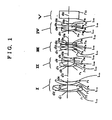
- the reference Roman numerals I, II, III, IV and V indicate a first group having a positive refractive power, a second group having a negative refractive power, a third group having a positive refractive power, a fourth group having a positive refractive power and an optically equivalent glass plate corresponding to a quartz-crystal filter and the face plate of an image device or the like, respectively.
- the first group I and third group III are unmovable in effecting both the zooming and the focusing.
- Variable power in the zooming process can be realized mainly by the move of the second group II, and the change in image-forming position induced in this case is corrected by moving the fourth group IV in response to the position of the second group II.
- the focusing is carried out by moving the fourth group IV.
- both the focusing and zooming can be effected by moving only two groups out of the above-mentioned four groups forming the zoom lens system, so that the optical system can be made simple in structure and economical to manufacture.
- the first group I since the first group I is not drawn out in the forward direction in the focusing process, diameters of respective lenses forming the first group I can be reduced, leading to the compactization.
- the change in the angle of view due to the move of the fourth group in the focusing process can be decreased up to a level that is practically negligible, which makes possible the realization of a high dignity focusing.
- a space d 16 between the third group III and the fourth group IV so as to be larger than the moving amount of the fourth group IV to prevent the same from coming into collision with the third group III in effecting the zooming and focusing processes, thus being capable of realizing a smaller closest range for photographing.
- the total length of the lens system will be slightly large, but the lenses forming the fourth group IV can be respectively made small in diameter and light in weight, so that the entire optical system including a driving unit can be advantageously attained compactization.
- the zoom lens of figure 1 is preferable to be arranged such that looking from the object side, the first group I has a negative lens L, a a positive lens L 12 and a positive meniscus lens L 13 , the second group has a negative meniscus lens L 21 , a negative lens L 22 and a positive lens L 23 , the third group III has two positive lenses L 31 and L 32 and a negative lens L 33 and the fourth group IV has a cemented lens made of a negative lens 41 and a positive lens L 42 and a positive lens 43.
- the illustrated zoom lens can correct both the monochromatic and chromatic aberrations of respective groups by using only 12 lens elements and good aberration performances can be realized over the entire zoom range from wide end to telephoto end as well as over the entire photographing distance from the infinite to the closest point.
- all groups are respectively configured of three lenses, so that well-balanced aberration correction can be realized.
- a first lens L 31 is a positive lens whose image side surface r 12 is convex
- a second lens L 32 is a positive lens whose object side surface r 13 is convex
- a third lens L 33 is a negative lens whose object side surface r 15 is concave.
- the aperture ratio is as large as about 1.4 in F-number
- spherical aberration and on-axis chromatic aberration can be satisfactorily corrected.
- the height of on-axis light ray can be prevented from increasing, thus making possible to decrease diameters of respective lenses forming the third group III.
- the positive lens L 31 and/or the positive lens L 32 are made of a double-convex lens and that curvature radii of the object side and the image side thereof are equal in the absolute value to each other. This offers a great advantage in manufacturing the zoom lens in that there is no need to pay attention to the possibility that it might be oppositely inserted during assembling.
- the fourth group IV is preferable to have a cemented lens whose cemented surface r 18 between the lenses L 41 and L 42 is convex to the object side direction and the positive lens L 43 whose object side surface r 20 is convex. So configured that coma aberration and lateral chromatic aberration can be satisfactorily corrected.
- f w entire focal length of wide angle end
- d 16 16th air space from the object side
- Condition (1) relates to the refractive power of the first group I.
- the refractive power of the group I becomes too large, so that correction of spherical aberration of the telephoto side becomes difficult.
- the lens length becomes large, resulting in being impossible to realize the compactization of the zoom lens.
- Condition (2) relates to the refractive power of the second group II.
- the compactization can be realized, but Petzval sum of the entire system becomes largely negative, so that correction of curvature of field cannot be realized only by selection of glass material to be used.
- the upper limit is exceeded, the aberration correction can become easy, but the amount of movement for zooming becomes large, thus being unable to realize the compactization of the entire lens system.
- Condition (3) relates to the refractive power of the third group III.
- the refractive power of this group III becomes too large, so that correction of spherical aberration of the wide angle side becomes difficult.
- the composite system of the groups I, II and III becomes a divergent system, so that the fourth group IV positioned successively adjacent thereto cannot have lenses reduced in diameter. Also, when being out of the upper and lower limit range, the change in the angle of view due to the move of the fourth group IV in the focusing process becomes large, so that image fluctuation cannot be made small.
- Condition (4) relates to the refractive power of the group IV.
- the quantity of light at a corner of the image becomes small, so that the diameter of the lens system of the first group I is required to be increased in order to obtain a desired quantity of light, thus being unable to realize the compactization.
- the upper limit is exceeded, correction of aberration becomes easy, but the moving amount of the fourth group IV becomes large when short-distance photographing is carried out, resulting in the fact that not only the compactization of the entire system cannot be realized, but also the correction of unbalanced off-axis aberration between the short-distance and long-distance photographings becomes difficult.
- Condition (5) relates to the air space between the groups III and IV.
- the lower limit When the lower limit is exceeded, the height of off-axis light ray becomes small, so that correction of lateral chromatic aberration becomes difficult to effect only by the selection of glass material to be used.
- a restriction is placed on the moving amount of the fourth group IV when carrying out a short-distance photographing, thus being impossible to realize a suitable closest range for photographing.
- the upper limit is exceeded, the entire system becomes difficult to be compactized. Further in addition, in order that suitable quantity of light is to be ensured around the image plane, the lens system of the fourth group IV cannot be reduced in diameter.
- Conditions (6), (7) and (8) relate to curvature radii of lenses forming the third group III.
- lower limits of conditions (6) and (7) When lower limits of conditions (6) and (7) are exceeded, incident angles of off-axis light ray to the surfaces r 12 and r 13 become large, thus being difficult to correct the off-axis coma aberration.
- upper limits of conditions (6) and (7) When upper limits of conditions (6) and (7) are exceeded, an under-corrected spherical aberration results.
- the lower limit of condition (8) is exceeded, an over-corrected spherical aberration results.
- the upper limit of condition (8) when the upper limit of condition (8) is exceeded, coma aberration for the off-axis light ray on the side under than the principal ray becomes difficult to be corrected.
- Conditions (9) and (10) relate to curvature radii of lenses forming the fourth group IV.
- lower limits of conditions (9) and (10) When lower limits of conditions (9) and (10) are exceeded, incident angles of a light ray to these surfaces r 18 and r 20 become large, thus being difficult to correct coma aberration for the off-axis light ray on the side over than the principal ray.
- the lower limit of condition (9) when the lower limit of condition (9) is exceeded, spherical aberration of a short wavelength light ray, i.e., F-line org-line, becomes difficult.
- the upper limit of condition (9) When the upper limit of condition (9) is exceeded, on-axis and lateral chromatic aberrations cannot be corrected in the range where a glass material to be used is practically available.
- the upper limit of condition (10) When the upper limit of condition (10) is exceeded, spherical aberration is difficult to be corrected.
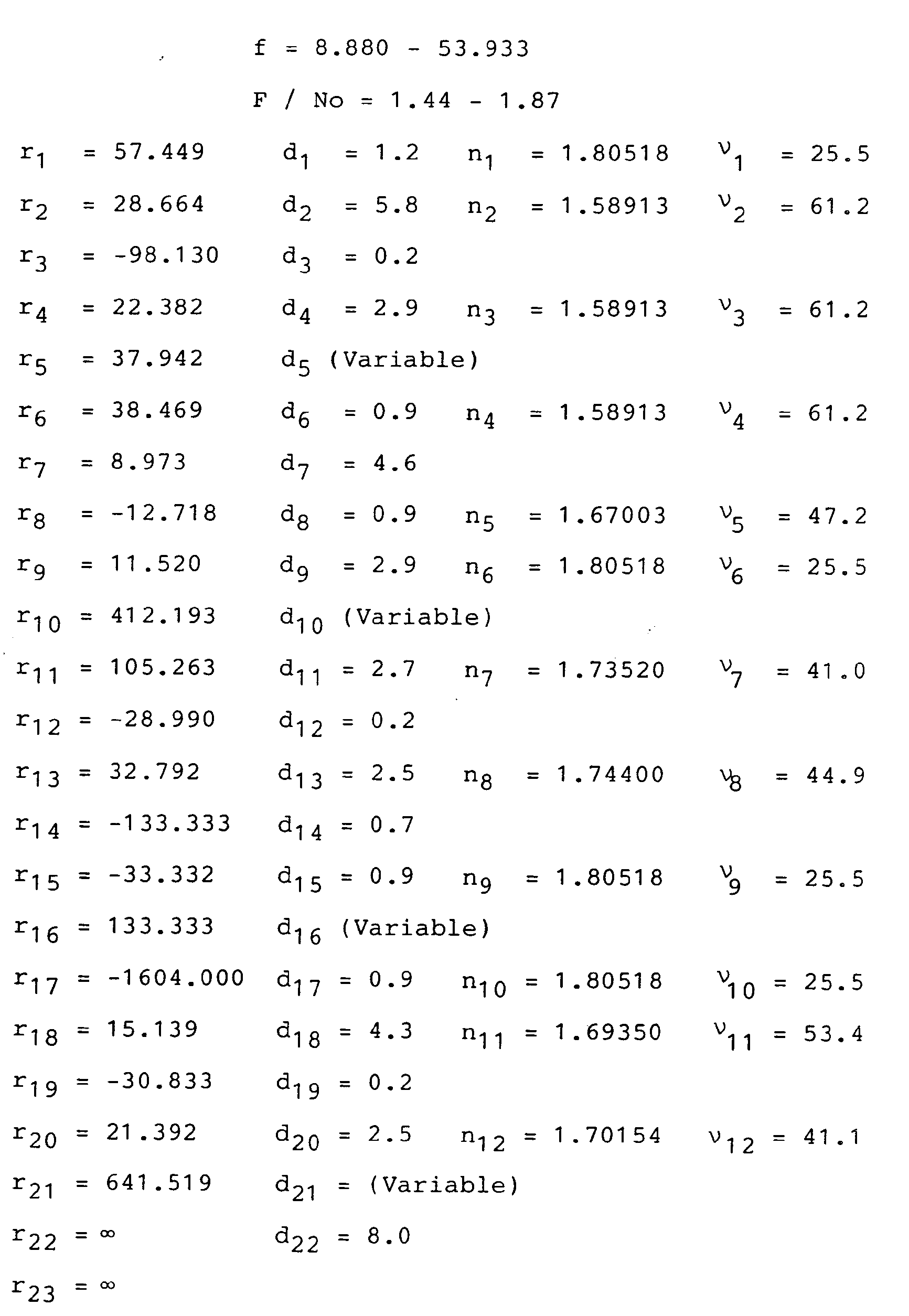
- r 1 , r 2 , ... and r 23 respectively indicate curvature radii of surfaces of lenses in the successive order from the object side
- d 1 , d 2 , ... and d 22 respectively indicate thicknesses of lenses or air spaces between adjacent lenses to each other
- n1, n 2 lenses for d-line respectively indicate Abbe numbers of lenses for the d-line.
- the alphabetical letter f indicates a focal length of the entire lens system and F/No indicates F-number.
- variable air spaces by zooming of this example will be exemplified as follows.
- the standard position is a zoom position where the fourth group IV is most approached to the third group III.
- variable air spaces by zooming of this example will be exemplified as follows.
- the standard position is a zoom position where the fourth group IV is most approached to the third group III.
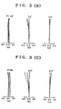
- Figs. 2 and 3 show aberration characteristics obtained in the first and second examples, respectively.
- (A) denotes aberration characteristics in the wide angle end
- (B) denotes aberration characteristics in an intermediate zoom position
- (C) denotes aberration characteristics in the telephoto end.
- (a) indicates spherical aberration (mm)
- (b) indicates astigmatism (mm)
- (c) indicates curvature of field (%).
- spherical aberration diagrams continuous lines, dotted lines and short dashes lines show spherical aberration characteristics of d-line, F-line and C-line, respectively.
- dotted lines and continuous lines show meridional image surfaces and sagittal image surfaces, respectively.
- a zoom lens arrangement according to the present invention is schematically cross-sectionally shown in Fig. 4.
- the zoom lens comprises, in the successive order from the object side, a first group I consisting of a negative lens L 11' a positive lens L 12 and a positive meniscus lens L i3 , a second group II consisting of a negative meniscus lens L 21 , a negative lens L 22 and a positive lens L 23 , a third group III consisting of a positive lens L 31 at least one of whose surfaces is aspherical and a fourth group IV consisting of a cemented lens made of lenses L 41 and L 42 at least one of whose surfaces are aspherically shaped.
- the zoom lens system of this embodiment makes possible that both the monochromatic and chromatic aberrations can be corrected by using only 9 lenses smaller in the number than in the above-mentioned examples and yet outstandingly preferable aberration characteristics can be realized over the entire zoom range from the wide angle end to the telephoto end as well as over the entire photographing distance from the infinite point to the closest point.
- the groups I and II are respectively made of three lenses, the group III intermediately placed as seen in Fig. 4 is made of a single aspherical lens and the group IV which is arranged at the closest position to the image side is made of two lenses having aspherical surfaces, thus making well-balanced correction of aberration possible.
- Such a condition that the third group III is made of an aspherical lens having a positive refractive power and being convex to the object side is an indispensable factor in order to make the third group of a single lens as well as to correct various aberrations, particularly spherical aberration, under such a condition that the aperture ratio is as large as abut 1.4 in F-number.
- f w entire focal length in the wide angle end
- d 12 twelveth airspace from the object side
- Conditions (11), (12), (13), (14) and (15) cover the same contents as those covered by conditions (1), (2), (3), (4) and (5), respectively.
- Condition (16) relates to the curvature radius of the surface r 11 on the object side of the aspherical lens L 31 of the third group III.
- the lens L 31 by making the surface r 11 on the object side and/or the surface r 12 on the image side aspherical and by optimizing the shape thereof, various aberrations can be satisfactorily corrected despite of using a single lens.
- the lower limit of condition (16) is exceeded, correction of spherical aberration becomes difficult, and when the upper limit thereof is exceeded, correction of coma aberration for the off-axis light ray on the side under than the principal ray becomes difficult.
- Condition (17) relates to the curvature radius of the cemented surface r 14 of the cemented lens of the fourth group IV.
- the negative refractive power lens L 41 and the positive refractive power lens L 42 forming the fourth group IV by making aspherical at least one of the surface r 13 on the object side of the lens 41, the cemented surface r 14 and the surface r 15 on the image side of the lens L 42 and by optimizing the shape thereof, monochromatic aberration can be satisfactorily corrected while correcting on-axis and lateral chromatic aberrations.
- the aspherical surface shape is defined by the following expression:
- variable air spaces by zooming of this embodiment will be exemplified as follows:
- the standard position is a zoom position where the fourth group IV is most approached to the third group III.
- variable air spaces by zooming of this embodiment will be exemplified as follows:
- the standard position is a zoom position where the fourth group IV is most approached to the third group III.
- the lenses of the first group I and second group II used in this Embodiment are identical to those used in Example 1.
- eleventh and fifteenth surfaces are aspherical whose aspherical coefficients are shown as follows:
- variable air spaces by zooming of this embodiment will be exemplified as follows:
- the standard position is a zoom position where the fourth group IV is most approached to the third group III.
- eleventh and thirteenth surfaces are aspherical whose aspherical coefficients are shown as follows:
- variable air spaces by zooming of this embodiment will be exemplified as follows:
- the standard position is a zoom position where the fourth group IV is most approached to the third group III.
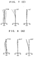
- Figs. 5, 6, 7 and 8 show aberration characteristics obtained in the first, second, third and fourth embodiments, respectively.
- A denotes aberration characteristics in the wide angle end
- B denotes aberration characteristics in an intermediate zoom position
- C denotes aberration characteristics in the telephoto end.
- (a) denotes spherical aberration (mm),
- continuous lines, dotted lines and short dashes lines show spherical aberration characteristics of d-line, F-line and C-line, respectively.
- dotted lines and continuous lines show meridional image surfaces and sagittal image surfaces, respectively.
Landscapes
- Physics & Mathematics (AREA)
- General Physics & Mathematics (AREA)
- Optics & Photonics (AREA)
- Lenses (AREA)
Description
- This invention relates to a zoom lens for use in a video camera, an electronic still camera or the like, which is compact in size and superior in performance.
- Recently, video cameras have required to effect a good operability and maneuverability as well as to produce a higher picture image quality. Under such a trend, small-sized as 1/2 or 1/3-inch and high resolution image devices are becoming playing a leading role in responding to these requirements. And, accompanied with which, it has been strongly emphasized to use zoom lenses which are large in aperture ratio, small in size and light in weight as well as high in performance. In addition, cost reduction has also been largely required. As a result, practical realization of zoom lenses which make possible the reduction in the number of lens components while performances are being maintained at a high level is of urgent necessity.
- Conventional video camera zoom lenses with the F-number of about 1.4 and zoom ratio of about six were so-called four-group lens system using more than 13 lens elements.
- Aconventional four-group zoom lens is disclosed in, for example, U.S. Pat. No. 4,749,267, in which, looking from the object side, the first group having a positive refractive power moves on the optical axis to effect focusing. The second group having a negative refractive power moves on the optical axis to effect zooming. The third group having a negative refractive power moves on the optical axis while holding a constant relation with the second group thereby to keep the image surface position to be changed with the move of the second group in a constant positional relation with the reference surface. The fourth group having a positive refractive power moves the image surface to be formed through the first, second and third groups to the desired position and yet carries out necessary aberration corrections to effect the realization of height picture image quality. On the focusing, the first group is drawn out in the forward direction, so that such problems have been pointed out that lenses to be used for forming this group become large in diameter and large in weight, which means that the compactization is difficult to be realized. Also, on the focusing, the angle of view is varied, so that an image can be fluctuated in the focusing process, which has been pointed out as a problem that can decrease the dignity of focusing.
- In order to solve the above-mentioned problems, a method in which other groups than the first group of a zoom lens are moved in the focusing process, so-called inner focusing method, has been conventionally employed.
- For example, a method of focusing by moving the third group is disclosed in U.S. Pat. No. 4,364,642 and another method of focusing by moving the second and third groups is disclosed in U.S. Pat. No. 4,460,251. With the above-mentioned methods, however, the moving amount of the lens group or groups becomes large in the focusing process, thus arising such a problem that the entire length of lens system cannot be reduced.
- In U.S. Pat. No. 4,859,042 is disclosed a method to provide the fourth group with a focusing function in order to solve these problems. In this case, however, the number of lenses of the third group becomes large (see
Embodiments - Another zoom lens arrangement is disclosed in US-A-4818083. This arrangement again includes four lens groups, the first having a positive focal length, the second having a negative focal length, the third having a positive focal length and the fourth having a positive focal length in the order from the object side. The first and third groups are kept fixed, the second lens group is movable to vary the focal length of the lens system as a whole and the fourth group is movable to compensate for the shift in focal point which occurs when the second group is moved. This system is subject to some of the disadvantages noted above including the need for a relatively large number of lenses.
- A similar system to that disclosed in US-A-4818083 is shown in JP-A-63-029719. Here the number of lens elements is relatively few, all embodiments having 11 or 12 individual lenses. It would still be advantageous to reduce the number of lenses even further to achieve a compact size.
- An object of this invention is to provide a zoom lens for use in video cameras, which is small in the number of lens elements to be used, large in aperture ratio, small in size and weight as well as high in performance.
- In orderto attain the above-mentioned object, a zoom lens of this invention comprises, in successive order from the object side, a first group of positive refractive power consisting of a negative lens, a positive lens and a positive meniscus lens; a second group of negative refractive power for affecting a variation of image magnification by moving along its optical axis, and consisting of a negative meniscus lens, a negative lens and a positive lens; a third group of positive refractive power; and a fourth group of positive refractive power moving along its optical axis so as to focus and to correct for defocusing when a variation in image magnification is affected by a movement of said second group, characterised in that said third group consists of a positive lens having at least one aspherical surface, and in that said fourth group consists of a cemented lens having at least one aspherical surface. The maximum air space between the third and fourth groups is preferably larger than the moving amount of the fourth group. Each group is of a lens type and has a surface shape preferable from the viewpoint of aberration performance.
- The third group is preferably made of a single aspherical lens having a positive refractive power.
- With the above-mentioned configuration, problems conventionally remained to be overcome can be solved, so that a high performance, small size and light weight zoom lens for use in video cameras can be practically realised, which has a small number of lens components and exhibits a F-number of about 1.4 and zoom ratio of about six.
- Embodiments of the invention will now be described by way of example only and with reference to the accompanying drawings in which:
- Figure 1 is a schematic sectional view of a lens arrangement from which the present invention has developed, shown for the purpose of explanation;
- Figures 2 and 3 are aberration characteristic diagrams for two specific examples of the lens arrangement shown in Figure 1;
- Figure 4 is a schematic sectional view of a lens arrangement according to the present invention; and
- Figures 5 to 8 are aberration characteristic diagrams of four embodiments of the present invention.
- In Fig. 1, the reference Roman numerals I, II, III, IV and V indicate a first group having a positive refractive power, a second group having a negative refractive power, a third group having a positive refractive power, a fourth group having a positive refractive power and an optically equivalent glass plate corresponding to a quartz-crystal filter and the face plate of an image device or the like, respectively.
- The first group I and third group III are unmovable in effecting both the zooming and the focusing. Variable power in the zooming process can be realized mainly by the move of the second group II, and the change in image-forming position induced in this case is corrected by moving the fourth group IV in response to the position of the second group II. The focusing is carried out by moving the fourth group IV. As a result, both the focusing and zooming can be effected by moving only two groups out of the above-mentioned four groups forming the zoom lens system, so that the optical system can be made simple in structure and economical to manufacture. In addition, since the first group I is not drawn out in the forward direction in the focusing process, diameters of respective lenses forming the first group I can be reduced, leading to the compactization.
- Further in addition, by selecting the refractive power of the first group to a positive, that of the second group to a negative and that of the third group to a positive, the change in the angle of view due to the move of the fourth group in the focusing process can be decreased up to a level that is practically negligible, which makes possible the realization of a high dignity focusing.
- It is preferable, in this case, to set a space d16 between the third group III and the fourth group IV so as to be larger than the moving amount of the fourth group IV to prevent the same from coming into collision with the third group III in effecting the zooming and focusing processes, thus being capable of realizing a smaller closest range for photographing. The total length of the lens system will be slightly large, but the lenses forming the fourth group IV can be respectively made small in diameter and light in weight, so that the entire optical system including a driving unit can be advantageously attained compactization.
- The zoom lens of figure 1 is preferable to be arranged such that looking from the object side, the first group I has a negative lens L, a a positive lens L12 and a positive meniscus lens L13, the second group has a negative meniscus lens L21, a negative lens L22 and a positive lens L23, the third group III has two positive lenses L31 and L32 and a negative lens L33 and the fourth group IV has a cemented lens made of a negative lens 41 and a positive lens L42 and a positive lens 43. So arranged as above that the illustrated zoom lens can correct both the monochromatic and chromatic aberrations of respective groups by using only 12 lens elements and good aberration performances can be realized over the entire zoom range from wide end to telephoto end as well as over the entire photographing distance from the infinite to the closest point. In addition, all groups are respectively configured of three lenses, so that well-balanced aberration correction can be realized. Referring to the third group III, looking from the object side, a first lens L31 is a positive lens whose image side surface r12 is convex, a second lens L32 is a positive lens whose object side surface r13 is convex and a third lens L33 is a negative lens whose object side surface r15 is concave. As a result, despite that the aperture ratio is as large as about 1.4 in F-number, spherical aberration and on-axis chromatic aberration can be satisfactorily corrected. Also, by arranging both two positive lenses on the object side, the height of on-axis light ray can be prevented from increasing, thus making possible to decrease diameters of respective lenses forming the third group III.
- Further referring to the third group III, it is preferable that the positive lens L31 and/or the positive lens L32 are made of a double-convex lens and that curvature radii of the object side and the image side thereof are equal in the absolute value to each other. This offers a great advantage in manufacturing the zoom lens in that there is no need to pay attention to the possibility that it might be oppositely inserted during assembling.
- Furthermore, the fourth group IV is preferable to have a cemented lens whose cemented surface r18 between the lenses L41 and L42 is convex to the object side direction and the positive lens L43 whose object side surface r20 is convex. So configured that coma aberration and lateral chromatic aberration can be satisfactorily corrected.
- Further in addition, when configured so as to satisfy the following conditions, aberration performances are outstandingly effective and a compact zoom lens can be realized with a reduced number of lenses:





- where, fw: entire focal length of wide angle end, f, (i=1, 2, 3, 4): focal length of i-th group lens system, d16: 16th air space from the object side, rj (j = 12, 13, 15, 18, 20): curvature radius of the lens surface of j-th lens.
- These conditions cover refractive powers, surface shapes or the like of lenses of respective groups, indicating ranges where compactization can be attained and satisfactory aberration performances can be realized with a reduced number of lens components.
- Next, description will be made in detail on each condition.
- Condition (1) relates to the refractive power of the first group I. When the lower limit is exceeded, the refractive power of the group I becomes too large, so that correction of spherical aberration of the telephoto side becomes difficult. When the upper limit is exceeded, the lens length becomes large, resulting in being impossible to realize the compactization of the zoom lens.
- Condition (2) relates to the refractive power of the second group II. When being out of the lower limit, the compactization can be realized, but Petzval sum of the entire system becomes largely negative, so that correction of curvature of field cannot be realized only by selection of glass material to be used. When the upper limit is exceeded, the aberration correction can become easy, but the amount of movement for zooming becomes large, thus being unable to realize the compactization of the entire lens system.
- Condition (3) relates to the refractive power of the third group III. When the lower limit is exceeded, the refractive power of this group III becomes too large, so that correction of spherical aberration of the wide angle side becomes difficult. When the upper limit is exceeded, the composite system of the groups I, II and III becomes a divergent system, so that the fourth group IV positioned successively adjacent thereto cannot have lenses reduced in diameter. Also, when being out of the upper and lower limit range, the change in the angle of view due to the move of the fourth group IV in the focusing process becomes large, so that image fluctuation cannot be made small.
- Condition (4) relates to the refractive power of the group IV. When being out of the lower limit, the quantity of light at a corner of the image becomes small, so that the diameter of the lens system of the first group I is required to be increased in order to obtain a desired quantity of light, thus being unable to realize the compactization. When the upper limit is exceeded, correction of aberration becomes easy, but the moving amount of the fourth group IV becomes large when short-distance photographing is carried out, resulting in the fact that not only the compactization of the entire system cannot be realized, but also the correction of unbalanced off-axis aberration between the short-distance and long-distance photographings becomes difficult.
- Condition (5) relates to the air space between the groups III and IV. When the lower limit is exceeded, the height of off-axis light ray becomes small, so that correction of lateral chromatic aberration becomes difficult to effect only by the selection of glass material to be used. In addition, a restriction is placed on the moving amount of the fourth group IV when carrying out a short-distance photographing, thus being impossible to realize a suitable closest range for photographing. When the upper limit is exceeded, the entire system becomes difficult to be compactized. Further in addition, in order that suitable quantity of light is to be ensured around the image plane, the lens system of the fourth group IV cannot be reduced in diameter.
- Conditions (6), (7) and (8) relate to curvature radii of lenses forming the third group III. When lower limits of conditions (6) and (7) are exceeded, incident angles of off-axis light ray to the surfaces r12 and r13 become large, thus being difficult to correct the off-axis coma aberration. When upper limits of conditions (6) and (7) are exceeded, an under-corrected spherical aberration results. On the other hand, when the lower limit of condition (8) is exceeded, an over-corrected spherical aberration results. Also, when the upper limit of condition (8) is exceeded, coma aberration for the off-axis light ray on the side under than the principal ray becomes difficult to be corrected.
- Conditions (9) and (10) relate to curvature radii of lenses forming the fourth group IV. When lower limits of conditions (9) and (10) are exceeded, incident angles of a light ray to these surfaces r18 and r20 become large, thus being difficult to correct coma aberration for the off-axis light ray on the side over than the principal ray. Also, when the lower limit of condition (9) is exceeded, spherical aberration of a short wavelength light ray, i.e., F-line org-line, becomes difficult. When the upper limit of condition (9) is exceeded, on-axis and lateral chromatic aberrations cannot be corrected in the range where a glass material to be used is practically available. When the upper limit of condition (10) is exceeded, spherical aberration is difficult to be corrected.
- Arrangements satisfying the conditions shown above will be shown below, in which, r1, r2, ... and r23 respectively indicate curvature radii of surfaces of lenses in the successive order from the object side, d1, d2, ... and d22 respectively indicate thicknesses of lenses or air spaces between adjacent lenses to each other, n1, n2 lenses for d-line, and ν1, ν2 ... and ν12 respectively indicate Abbe numbers of lenses for the d-line. The alphabetical letter f indicates a focal length of the entire lens system and F/No indicates F-number.
-
- Next, variable air spaces by zooming of this example will be exemplified as follows.
- When an object point distanced 2 m from the first surface r1 of the lens L11 in Fig. 1, the following data were obtained:

- Where, the standard position is a zoom position where the fourth group IV is most approached to the third group III.

-

- Next, variable air spaces by zooming of this example will be exemplified as follows.
- When an object point distanced 2 m from the first surface r1 of the lens L11 shown in Fig. 1, the following data were obtained:
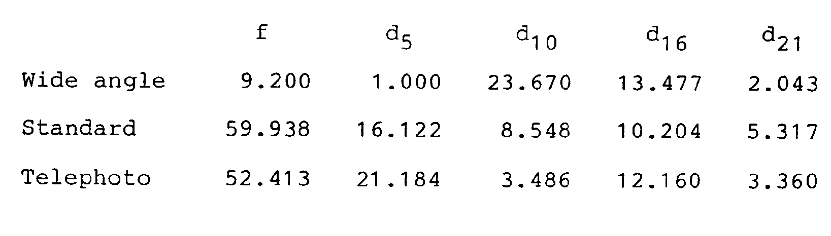
- Where, the standard position is a zoom position where the fourth group IV is most approached to the third group III.

- Figs. 2 and 3 show aberration characteristics obtained in the first and second examples, respectively. In these figures, (A) denotes aberration characteristics in the wide angle end, (B) denotes aberration characteristics in an intermediate zoom position and (C) denotes aberration characteristics in the telephoto end. Also, in each of figures denoted at (A), (B) and (C), (a) indicates spherical aberration (mm), (b) indicates astigmatism (mm) and (c) indicates curvature of field (%). In the spherical aberration diagrams, continuous lines, dotted lines and short dashes lines show spherical aberration characteristics of d-line, F-line and C-line, respectively. In the astigmatism diagrams, dotted lines and continuous lines show meridional image surfaces and sagittal image surfaces, respectively.
- From these diagrams, it is clear that the lens systems according to the first and second examples shown above respectively exhibit good optical performances.
- A zoom lens arrangement according to the present invention is schematically cross-sectionally shown in Fig. 4. In Fig. 4, the zoom lens comprises, in the successive order from the object side, a first group I consisting of a negative lens L11' a positive lens L12 and a positive meniscus lens Li3, a second group II consisting of a negative meniscus lens L21, a negative lens L22 and a positive lens L23, a third group III consisting of a positive lens L31 at least one of whose surfaces is aspherical and a fourth group IV consisting of a cemented lens made of lenses L41 and L42 at least one of whose surfaces are aspherically shaped. So arranged that the zoom lens system of this embodiment makes possible that both the monochromatic and chromatic aberrations can be corrected by using only 9 lenses smaller in the number than in the above-mentioned examples and yet outstandingly preferable aberration characteristics can be realized over the entire zoom range from the wide angle end to the telephoto end as well as over the entire photographing distance from the infinite point to the closest point. In addition, the groups I and II are respectively made of three lenses, the group III intermediately placed as seen in Fig. 4 is made of a single aspherical lens and the group IV which is arranged at the closest position to the image side is made of two lenses having aspherical surfaces, thus making well-balanced correction of aberration possible.
- Such a condition that the third group III is made of an aspherical lens having a positive refractive power and being convex to the object side is an indispensable factor in order to make the third group of a single lens as well as to correct various aberrations, particularly spherical aberration, under such a condition that the aperture ratio is as large as abut 1.4 in F-number.
- In the fourth group IV, to make aspherical at least one of surfaces of the lenses L41 and L42 forming the cemented lens and yet to make the cemented surface r14 convex to the object side are preferable. So configured that coma aberration and magnification chromatic aberration can be satisfactorily corrected by using only 2 lenses.
- In addition, when configured so as to satisfy the following conditions, aberration performances are extremely superior and a compact zoom lens can be realized with a small number of lens components:



- Where, fw: entire focal length in the wide angle end, f1 (i = 1, 2, 3, 4): focal length of the i-th group, d12: twelveth airspace from the object side, rj (j = 11, 14): curvature radius of the j-th lens surface.
- These conditions cover refractive powers, surface shapes or the like of lenses of respective groups, indicating ranges where compactization can be attained and satisfactory aberration performances can be realized with a reduced number of lens components.
- Next, description will be made in detail on these conditions.
- Conditions (11), (12), (13), (14) and (15) cover the same contents as those covered by conditions (1), (2), (3), (4) and (5), respectively.
- Condition (16) relates to the curvature radius of the surface r11 on the object side of the aspherical lens L31 of the third group III. Of the lens L31, by making the surface r11 on the object side and/or the surface r12 on the image side aspherical and by optimizing the shape thereof, various aberrations can be satisfactorily corrected despite of using a single lens. However, when the lower limit of condition (16) is exceeded, correction of spherical aberration becomes difficult, and when the upper limit thereof is exceeded, correction of coma aberration for the off-axis light ray on the side under than the principal ray becomes difficult.
- Condition (17) relates to the curvature radius of the cemented surface r14 of the cemented lens of the fourth group IV. Of the negative refractive power lens L41 and the positive refractive power lens L42 forming the fourth group IV, by making aspherical at least one of the surface r13 on the object side of the lens 41, the cemented surface r14 and the surface r15 on the image side of the lens L42 and by optimizing the shape thereof, monochromatic aberration can be satisfactorily corrected while correcting on-axis and lateral chromatic aberrations. However, when the lower limit of condition (17) is exceeded, incident angles of a light ray to these surfaces become large, so that correction of coma aberration for the off-axis light ray on the side over than the principal ray becomes difficult as well as an over-corrected spherical aberration results for the F-line. When the upper limit is exceeded, on-axis and lateral chromatic aberrations cannot be corrected in the range where a glass material to be used is practically available.
- Embodiments satisfiable these conditions shown above will be shown below. Symbols used in these embodiments are identical to those used in examples 1 and 2.
- In addition, the aspherical surface shape is defined by the following expression:

- where, Z: distance of a point on the aspherical surface from the contact plane at the vertex of aspherical surface when the height from the optical axis is expressed by Y
- Y: height from the optical axis
- C: Curvature radius of the vertex of aspherical surface (= 1 / r)
- K: Conical constant
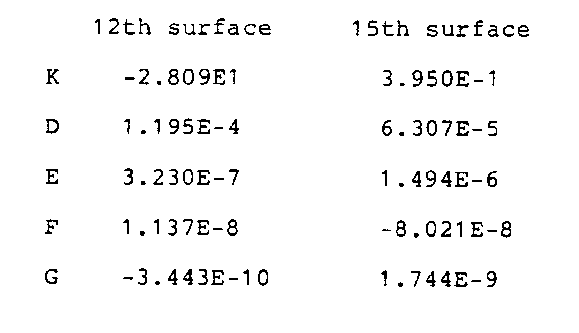
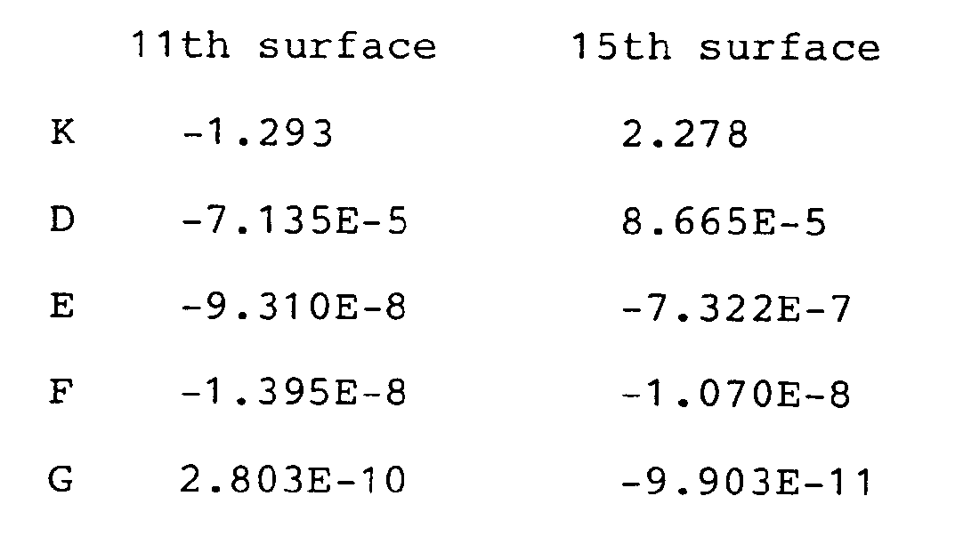
- D, E, F, G: Aspherical coefficient
-

- In addition, twelveth and fifteenth surfaces are aspherical whose aspherical coefficients are shown as follows:
- Next, variable air spaces by zooming of this embodiment will be exemplified as follows:
- When an object point distanced 2 m from the first surface r1 of the lens L11 shown in Fig. 4, the following data were obtained:

- Where, the standard position is a zoom position where the fourth group IV is most approached to the third group III.

-

- In addition, twelveth and fifteenth surfaces are aspherical whose aspherical coefficients are shown as follows:

- Next, variable air spaces by zooming of this embodiment will be exemplified as follows:
- When an object point distanced 2 m from the first surface r1 of the lens L11 shown in Fig. 4, the following data were obtained:

- Where, the standard position is a zoom position where the fourth group IV is most approached to the third group III.

-

- The lenses of the first group I and second group II used in this Embodiment are identical to those used in Example 1.
- In addition, eleventh and fifteenth surfaces are aspherical whose aspherical coefficients are shown as follows:
- Next, variable air spaces by zooming of this embodiment will be exemplified as follows:
- When an object point distanced 2 m from the first surface r1 of the lens L11 in Fig. 4, the following date were obtained:

- Where, the standard position is a zoom position where the fourth group IV is most approached to the third group III.

-

- The lenses of the first group I and second group II used in this Embodiment are identical to those used in
- In addition, eleventh and thirteenth surfaces are aspherical whose aspherical coefficients are shown as follows:

- Next, variable air spaces by zooming of this embodiment will be exemplified as follows:
- When an object point distanced 2 m from the first surface r1 of the lens L11 in Fig. 4, the following data were obtained:

- Where, the standard position is a zoom position where the fourth group IV is most approached to the third group III.

- From the diagrams, it is clear that these lens systems according to these embodiments respectively exhibit good optical performances.
Claims (5)


Applications Claiming Priority (4)
| Application Number | Priority Date | Filing Date | Title |
|---|---|---|---|
| JP1163058A JPH07111503B2 (en) | 1989-06-26 | 1989-06-26 | Zoom lens |
| JP163058/89 | 1989-06-26 | ||
| JP1169295A JP2502754B2 (en) | 1989-06-29 | 1989-06-29 | Aspherical zoom lens |
| JP169295/89 | 1989-06-29 |
Publications (4)
| Publication Number | Publication Date |
|---|---|
| EP0405856A2 EP0405856A2 (en) | 1991-01-02 |
| EP0405856A3 EP0405856A3 (en) | 1991-10-09 |
| EP0405856B1 true EP0405856B1 (en) | 1995-09-20 |
| EP0405856B2 EP0405856B2 (en) | 1999-02-03 |
Family
ID=26488627
Family Applications (1)
| Application Number | Title | Priority Date | Filing Date |
|---|---|---|---|
| EP90306851A Expired - Lifetime EP0405856B2 (en) | 1989-06-26 | 1990-06-22 | Zoom lens |
Country Status (3)
| Country | Link |
|---|---|
| US (1) | US5100223A (en) |
| EP (1) | EP0405856B2 (en) |
| DE (1) | DE69022493T3 (en) |
Families Citing this family (17)
| Publication number | Priority date | Publication date | Assignee | Title |
|---|---|---|---|---|
| US5202992A (en) * | 1990-04-27 | 1993-04-13 | Konica Corporation | Zoom lens apparatus |
| DE69223268T2 (en) * | 1991-03-29 | 1998-04-16 | Canon Kk | Zoom lens with focus through the rear lens groups |
| JP3033274B2 (en) * | 1991-09-12 | 2000-04-17 | 松下電器産業株式会社 | Aspherical zoom lens and video camera using it |
| JP3033276B2 (en) * | 1991-09-18 | 2000-04-17 | 松下電器産業株式会社 | Wide-angle aspheric zoom lens |
| US5359457A (en) * | 1991-10-03 | 1994-10-25 | Minolta Camera Co., Ltd. | Wide-angle zoom lens system |
| US5565919A (en) * | 1992-03-12 | 1996-10-15 | Hitachi, Ltd. | Video camera/VTR and camera station with opto-electronic link between camera/VTR and camera station |
| JP2607773Y2 (en) * | 1992-03-24 | 2002-07-08 | 富士写真光機株式会社 | Optical system |
| EP0566073B1 (en) | 1992-04-17 | 1996-12-18 | Matsushita Electric Industrial Co., Ltd. | Zoom lens assembly |
| JPH0634882A (en) * | 1992-07-22 | 1994-02-10 | Sony Corp | Zoom lens |
| US5583698A (en) * | 1993-06-07 | 1996-12-10 | Matsushita Electric Industrial Co., Ltd. | Aspherical zoom lens |
| JPH07209582A (en) * | 1994-01-18 | 1995-08-11 | Konica Corp | Zoom lens using plastic lens |
| US6222681B1 (en) | 1996-08-30 | 2001-04-24 | Minolta, Co., Ltd. | Zoom lens system |
| US6101043A (en) * | 1998-02-26 | 2000-08-08 | Minolta Co., Ltd. | Zoom lens system |
| JP3391342B2 (en) | 1999-10-29 | 2003-03-31 | ミノルタ株式会社 | Imaging lens device |
| JP2003315676A (en) * | 2002-04-19 | 2003-11-06 | Pentax Corp | Zoom lens system |
| US6853496B2 (en) * | 2002-08-13 | 2005-02-08 | Pentax Corporation | Zoom lens system |
| CN106199932B (en) * | 2016-08-29 | 2019-11-26 | 中国科学院长春光学精密机械与物理研究所 | A kind of zoom lens |
Family Cites Families (7)
| Publication number | Priority date | Publication date | Assignee | Title |
|---|---|---|---|---|
| JPS53107347A (en) * | 1977-03-01 | 1978-09-19 | Canon Inc | Zoom lens |
| JPS592884B2 (en) * | 1979-07-28 | 1984-01-21 | 旭光学工業株式会社 | Zoom lens focus method |
| JPS57172310A (en) * | 1981-04-17 | 1982-10-23 | Canon Inc | Zoom lens |
| US4653872A (en) * | 1981-04-22 | 1987-03-31 | Nippon Kogaku K. K. | Athermalized zoom lens system |
| JPH0668574B2 (en) * | 1984-06-27 | 1994-08-31 | オリンパス光学工業株式会社 | Large aperture variable magnification lens system |
| JP2538526B2 (en) * | 1986-03-17 | 1996-09-25 | キヤノン株式会社 | Zoom lens |
| JP2737838B2 (en) * | 1986-11-13 | 1998-04-08 | オリンパス光学工業株式会社 | Variable power lens system |
-
1990
- 1990-06-21 US US07/541,735 patent/US5100223A/en not_active Expired - Lifetime
- 1990-06-22 EP EP90306851A patent/EP0405856B2/en not_active Expired - Lifetime
- 1990-06-22 DE DE69022493T patent/DE69022493T3/en not_active Expired - Fee Related
Also Published As
| Publication number | Publication date |
|---|---|
| EP0405856B2 (en) | 1999-02-03 |
| DE69022493T3 (en) | 1999-06-02 |
| DE69022493T2 (en) | 1996-05-09 |
| EP0405856A3 (en) | 1991-10-09 |
| DE69022493D1 (en) | 1995-10-26 |
| EP0405856A2 (en) | 1991-01-02 |
| US5100223A (en) | 1992-03-31 |
Similar Documents
| Publication | Publication Date | Title |
|---|---|---|
| US6016228A (en) | Zoom lens system | |
| US6320698B1 (en) | Zoom lens with vibration reduction function | |
| EP0401862B1 (en) | Zoom lens of rear focus type | |
| US5585966A (en) | Zoom lens with vibration reduction function | |
| US4874231A (en) | Zoom lens | |
| US4830476A (en) | Compact zoom lens system | |
| JP2778232B2 (en) | Wide-angle zoom lens | |
| US6246519B1 (en) | Zoom lens system with vibration reduction function | |
| JPH05173071A (en) | Wide angle zoom lens | |
| EP0620467B1 (en) | Wide-angle aspheric zoom lens | |
| EP0405856B2 (en) | Zoom lens | |
| JPH05264902A (en) | Zoom lens | |
| US5270863A (en) | Zoom lens system | |
| JP3066915B2 (en) | Zoom lens | |
| JPH09258102A (en) | Zoom lens of inner focusing type | |
| JP3018723B2 (en) | Zoom lens | |
| US4159865A (en) | Zoom lens system | |
| JPH0642017B2 (en) | Compact zoom lens | |
| EP0533077B1 (en) | Zoom lens | |
| US5764421A (en) | Zoom lens system having minimal aberration fluctuation at short object distance | |
| US6788474B2 (en) | Zoom image pickup optical system | |
| JP3085823B2 (en) | Aspherical zoom lens and video camera using it | |
| JP2513481B2 (en) | Zoom lens | |
| US4749267A (en) | Large aperture ratio zoom lens system | |
| JPH06230283A (en) | Zoom lens |
Legal Events
| Date | Code | Title | Description |
|---|---|---|---|
| PUAI | Public reference made under article 153(3) epc to a published international application that has entered the european phase |
Free format text: ORIGINAL CODE: 0009012 |
|
| AK | Designated contracting states |
Kind code of ref document: A2 Designated state(s): DE FR GB |
|
| PUAL | Search report despatched |
Free format text: ORIGINAL CODE: 0009013 |
|
| AK | Designated contracting states |
Kind code of ref document: A3 Designated state(s): DE FR GB |
|
| 17P | Request for examination filed |
Effective date: 19920316 |
|
| 17Q | First examination report despatched |
Effective date: 19940506 |
|
| GRAA | (expected) grant |
Free format text: ORIGINAL CODE: 0009210 |
|
| AK | Designated contracting states |
Kind code of ref document: B1 Designated state(s): DE FR GB |
|
| REF | Corresponds to: |
Ref document number: 69022493 Country of ref document: DE Date of ref document: 19951026 |
|
| ET | Fr: translation filed | ||
| PLBQ | Unpublished change to opponent data |
Free format text: ORIGINAL CODE: EPIDOS OPPO |
|
| PLBI | Opposition filed |
Free format text: ORIGINAL CODE: 0009260 |
|
| PLBF | Reply of patent proprietor to notice(s) of opposition |
Free format text: ORIGINAL CODE: EPIDOS OBSO |
|
| 26 | Opposition filed |
Opponent name: CANON INC. CORPORATE INTELLECTUAL PROPERTY AND LEG Effective date: 19960620 |
|
| PLBF | Reply of patent proprietor to notice(s) of opposition |
Free format text: ORIGINAL CODE: EPIDOS OBSO |
|
| PLBF | Reply of patent proprietor to notice(s) of opposition |
Free format text: ORIGINAL CODE: EPIDOS OBSO |
|
| PLAW | Interlocutory decision in opposition |
Free format text: ORIGINAL CODE: EPIDOS IDOP |
|
| PLAW | Interlocutory decision in opposition |
Free format text: ORIGINAL CODE: EPIDOS IDOP |
|
| PUAH | Patent maintained in amended form |
Free format text: ORIGINAL CODE: 0009272 |
|
| STAA | Information on the status of an ep patent application or granted ep patent |
Free format text: STATUS: PATENT MAINTAINED AS AMENDED |
|
| 27A | Patent maintained in amended form |
Effective date: 19990203 |
|
| AK | Designated contracting states |
Kind code of ref document: B2 Designated state(s): DE FR GB |
|
| ET3 | Fr: translation filed ** decision concerning opposition | ||
| REG | Reference to a national code |
Ref country code: GB Ref legal event code: IF02 |
|
| PGFP | Annual fee paid to national office [announced via postgrant information from national office to epo] |
Ref country code: FR Payment date: 20050608 Year of fee payment: 16 |
|
| PGFP | Annual fee paid to national office [announced via postgrant information from national office to epo] |
Ref country code: DE Payment date: 20050616 Year of fee payment: 16 |
|
| PGFP | Annual fee paid to national office [announced via postgrant information from national office to epo] |
Ref country code: GB Payment date: 20050622 Year of fee payment: 16 |
|
| PG25 | Lapsed in a contracting state [announced via postgrant information from national office to epo] |
Ref country code: GB Free format text: LAPSE BECAUSE OF NON-PAYMENT OF DUE FEES Effective date: 20060622 |
|
| PG25 | Lapsed in a contracting state [announced via postgrant information from national office to epo] |
Ref country code: DE Free format text: LAPSE BECAUSE OF NON-PAYMENT OF DUE FEES Effective date: 20070103 |
|
| GBPC | Gb: european patent ceased through non-payment of renewal fee |
Effective date: 20060622 |
|
| REG | Reference to a national code |
Ref country code: FR Ref legal event code: ST Effective date: 20070228 |
|
| PG25 | Lapsed in a contracting state [announced via postgrant information from national office to epo] |
Ref country code: FR Free format text: LAPSE BECAUSE OF NON-PAYMENT OF DUE FEES Effective date: 20060630 |