EP0405447A2 - Fuel filter - Google Patents
Fuel filter Download PDFInfo
- Publication number
- EP0405447A2 EP0405447A2 EP90112130A EP90112130A EP0405447A2 EP 0405447 A2 EP0405447 A2 EP 0405447A2 EP 90112130 A EP90112130 A EP 90112130A EP 90112130 A EP90112130 A EP 90112130A EP 0405447 A2 EP0405447 A2 EP 0405447A2
- Authority
- EP
- European Patent Office
- Prior art keywords
- fuel
- endcap
- conduit
- defining
- housing
- Prior art date
- Legal status (The legal status is an assumption and is not a legal conclusion. Google has not performed a legal analysis and makes no representation as to the accuracy of the status listed.)
- Granted
Links
- 239000000446 fuel Substances 0.000 title claims abstract description 162
- XLYOFNOQVPJJNP-UHFFFAOYSA-N water Substances O XLYOFNOQVPJJNP-UHFFFAOYSA-N 0.000 claims abstract description 57
- 239000013618 particulate matter Substances 0.000 claims abstract description 9
- 238000007789 sealing Methods 0.000 claims description 49
- 238000010438 heat treatment Methods 0.000 claims description 11
- 230000002093 peripheral effect Effects 0.000 claims description 11
- 239000012530 fluid Substances 0.000 claims description 10
- 238000004891 communication Methods 0.000 claims description 6
- 238000001914 filtration Methods 0.000 claims description 6
- 239000000463 material Substances 0.000 claims description 2
- 238000011179 visual inspection Methods 0.000 claims description 2
- 150000001875 compounds Chemical class 0.000 claims 1
- 230000004888 barrier function Effects 0.000 abstract description 4
- 230000009977 dual effect Effects 0.000 abstract description 4
- 230000000717 retained effect Effects 0.000 abstract 1
- 239000000853 adhesive Substances 0.000 description 5
- 230000001070 adhesive effect Effects 0.000 description 5
- 239000013078 crystal Substances 0.000 description 5
- 239000002283 diesel fuel Substances 0.000 description 5
- 238000002347 injection Methods 0.000 description 4
- 239000007924 injection Substances 0.000 description 4
- 239000002245 particle Substances 0.000 description 4
- 238000002485 combustion reaction Methods 0.000 description 3
- 229920001944 Plastisol Polymers 0.000 description 2
- 230000015572 biosynthetic process Effects 0.000 description 2
- 239000004999 plastisol Substances 0.000 description 2
- 238000001556 precipitation Methods 0.000 description 2
- 230000006978 adaptation Effects 0.000 description 1
- 230000002411 adverse Effects 0.000 description 1
- 230000004323 axial length Effects 0.000 description 1
- 239000011230 binding agent Substances 0.000 description 1
- 230000000295 complement effect Effects 0.000 description 1
- 239000000470 constituent Substances 0.000 description 1
- 238000010276 construction Methods 0.000 description 1
- 230000000694 effects Effects 0.000 description 1
- 238000007667 floating Methods 0.000 description 1
- 230000008014 freezing Effects 0.000 description 1
- 238000007710 freezing Methods 0.000 description 1
- 238000010348 incorporation Methods 0.000 description 1
- 238000007373 indentation Methods 0.000 description 1
- 239000007788 liquid Substances 0.000 description 1
- 238000012986 modification Methods 0.000 description 1
- 230000004048 modification Effects 0.000 description 1
- 239000011236 particulate material Substances 0.000 description 1
- 239000002244 precipitate Substances 0.000 description 1
- 230000001376 precipitating effect Effects 0.000 description 1
- 230000037452 priming Effects 0.000 description 1
- 238000003908 quality control method Methods 0.000 description 1
- 239000011347 resin Substances 0.000 description 1
- 229920005989 resin Polymers 0.000 description 1
- 229920006395 saturated elastomer Polymers 0.000 description 1
- 229910052710 silicon Inorganic materials 0.000 description 1
- 239000010703 silicon Substances 0.000 description 1
- 239000000126 substance Substances 0.000 description 1
- 238000011144 upstream manufacturing Methods 0.000 description 1
Images


Classifications
-
- F—MECHANICAL ENGINEERING; LIGHTING; HEATING; WEAPONS; BLASTING
- F01—MACHINES OR ENGINES IN GENERAL; ENGINE PLANTS IN GENERAL; STEAM ENGINES
- F01M—LUBRICATING OF MACHINES OR ENGINES IN GENERAL; LUBRICATING INTERNAL COMBUSTION ENGINES; CRANKCASE VENTILATING
- F01M11/00—Component parts, details or accessories, not provided for in, or of interest apart from, groups F01M1/00 - F01M9/00
- F01M11/03—Mounting or connecting of lubricant purifying means relative to the machine or engine; Details of lubricant purifying means
-
- B—PERFORMING OPERATIONS; TRANSPORTING
- B01—PHYSICAL OR CHEMICAL PROCESSES OR APPARATUS IN GENERAL
- B01D—SEPARATION
- B01D29/00—Filters with filtering elements stationary during filtration, e.g. pressure or suction filters, not covered by groups B01D24/00 - B01D27/00; Filtering elements therefor
- B01D29/11—Filters with filtering elements stationary during filtration, e.g. pressure or suction filters, not covered by groups B01D24/00 - B01D27/00; Filtering elements therefor with bag, cage, hose, tube, sleeve or like filtering elements
- B01D29/114—Filters with filtering elements stationary during filtration, e.g. pressure or suction filters, not covered by groups B01D24/00 - B01D27/00; Filtering elements therefor with bag, cage, hose, tube, sleeve or like filtering elements arranged for inward flow filtration
-
- B—PERFORMING OPERATIONS; TRANSPORTING
- B01—PHYSICAL OR CHEMICAL PROCESSES OR APPARATUS IN GENERAL
- B01D—SEPARATION
- B01D17/00—Separation of liquids, not provided for elsewhere, e.g. by thermal diffusion
-
- B—PERFORMING OPERATIONS; TRANSPORTING
- B01—PHYSICAL OR CHEMICAL PROCESSES OR APPARATUS IN GENERAL
- B01D—SEPARATION
- B01D17/00—Separation of liquids, not provided for elsewhere, e.g. by thermal diffusion
- B01D17/02—Separation of non-miscible liquids
- B01D17/0208—Separation of non-miscible liquids by sedimentation
-
- B—PERFORMING OPERATIONS; TRANSPORTING
- B01—PHYSICAL OR CHEMICAL PROCESSES OR APPARATUS IN GENERAL
- B01D—SEPARATION
- B01D17/00—Separation of liquids, not provided for elsewhere, e.g. by thermal diffusion
- B01D17/02—Separation of non-miscible liquids
- B01D17/04—Breaking emulsions
- B01D17/042—Breaking emulsions by changing the temperature
-
- B—PERFORMING OPERATIONS; TRANSPORTING
- B01—PHYSICAL OR CHEMICAL PROCESSES OR APPARATUS IN GENERAL
- B01D—SEPARATION
- B01D17/00—Separation of liquids, not provided for elsewhere, e.g. by thermal diffusion
- B01D17/02—Separation of non-miscible liquids
- B01D17/04—Breaking emulsions
- B01D17/045—Breaking emulsions with coalescers
-
- B—PERFORMING OPERATIONS; TRANSPORTING
- B01—PHYSICAL OR CHEMICAL PROCESSES OR APPARATUS IN GENERAL
- B01D—SEPARATION
- B01D17/00—Separation of liquids, not provided for elsewhere, e.g. by thermal diffusion
- B01D17/08—Thickening liquid suspensions by filtration
-
- B—PERFORMING OPERATIONS; TRANSPORTING
- B01—PHYSICAL OR CHEMICAL PROCESSES OR APPARATUS IN GENERAL
- B01D—SEPARATION
- B01D27/00—Cartridge filters of the throw-away type
- B01D27/08—Construction of the casing
-
- B—PERFORMING OPERATIONS; TRANSPORTING
- B01—PHYSICAL OR CHEMICAL PROCESSES OR APPARATUS IN GENERAL
- B01D—SEPARATION
- B01D27/00—Cartridge filters of the throw-away type
- B01D27/14—Cartridge filters of the throw-away type having more than one filtering element
- B01D27/142—Cartridge filters of the throw-away type having more than one filtering element connected in parallel
- B01D27/144—Cartridge filters of the throw-away type having more than one filtering element connected in parallel arranged concentrically or coaxially
-
- B—PERFORMING OPERATIONS; TRANSPORTING
- B01—PHYSICAL OR CHEMICAL PROCESSES OR APPARATUS IN GENERAL
- B01D—SEPARATION
- B01D29/00—Filters with filtering elements stationary during filtration, e.g. pressure or suction filters, not covered by groups B01D24/00 - B01D27/00; Filtering elements therefor
- B01D29/11—Filters with filtering elements stationary during filtration, e.g. pressure or suction filters, not covered by groups B01D24/00 - B01D27/00; Filtering elements therefor with bag, cage, hose, tube, sleeve or like filtering elements
- B01D29/117—Filters with filtering elements stationary during filtration, e.g. pressure or suction filters, not covered by groups B01D24/00 - B01D27/00; Filtering elements therefor with bag, cage, hose, tube, sleeve or like filtering elements arranged for outward flow filtration
-
- B—PERFORMING OPERATIONS; TRANSPORTING
- B01—PHYSICAL OR CHEMICAL PROCESSES OR APPARATUS IN GENERAL
- B01D—SEPARATION
- B01D29/00—Filters with filtering elements stationary during filtration, e.g. pressure or suction filters, not covered by groups B01D24/00 - B01D27/00; Filtering elements therefor
- B01D29/50—Filters with filtering elements stationary during filtration, e.g. pressure or suction filters, not covered by groups B01D24/00 - B01D27/00; Filtering elements therefor with multiple filtering elements, characterised by their mutual disposition
- B01D29/56—Filters with filtering elements stationary during filtration, e.g. pressure or suction filters, not covered by groups B01D24/00 - B01D27/00; Filtering elements therefor with multiple filtering elements, characterised by their mutual disposition in series connection
- B01D29/58—Filters with filtering elements stationary during filtration, e.g. pressure or suction filters, not covered by groups B01D24/00 - B01D27/00; Filtering elements therefor with multiple filtering elements, characterised by their mutual disposition in series connection arranged concentrically or coaxially
-
- B—PERFORMING OPERATIONS; TRANSPORTING
- B01—PHYSICAL OR CHEMICAL PROCESSES OR APPARATUS IN GENERAL
- B01D—SEPARATION
- B01D29/00—Filters with filtering elements stationary during filtration, e.g. pressure or suction filters, not covered by groups B01D24/00 - B01D27/00; Filtering elements therefor
- B01D29/76—Handling the filter cake in the filter for purposes other than for regenerating
- B01D29/80—Handling the filter cake in the filter for purposes other than for regenerating for drying
- B01D29/84—Handling the filter cake in the filter for purposes other than for regenerating for drying by gases or by heating
- B01D29/846—Handling the filter cake in the filter for purposes other than for regenerating for drying by gases or by heating by indirect heat-exchange
-
- B—PERFORMING OPERATIONS; TRANSPORTING
- B01—PHYSICAL OR CHEMICAL PROCESSES OR APPARATUS IN GENERAL
- B01D—SEPARATION
- B01D35/00—Filtering devices having features not specifically covered by groups B01D24/00 - B01D33/00, or for applications not specifically covered by groups B01D24/00 - B01D33/00; Auxiliary devices for filtration; Filter housing constructions
- B01D35/18—Heating or cooling the filters
-
- B—PERFORMING OPERATIONS; TRANSPORTING
- B01—PHYSICAL OR CHEMICAL PROCESSES OR APPARATUS IN GENERAL
- B01D—SEPARATION
- B01D36/00—Filter circuits or combinations of filters with other separating devices
- B01D36/001—Filters in combination with devices for the removal of gas, air purge systems
-
- B—PERFORMING OPERATIONS; TRANSPORTING
- B01—PHYSICAL OR CHEMICAL PROCESSES OR APPARATUS IN GENERAL
- B01D—SEPARATION
- B01D36/00—Filter circuits or combinations of filters with other separating devices
- B01D36/003—Filters in combination with devices for the removal of liquids
-
- B—PERFORMING OPERATIONS; TRANSPORTING
- B01—PHYSICAL OR CHEMICAL PROCESSES OR APPARATUS IN GENERAL
- B01D—SEPARATION
- B01D36/00—Filter circuits or combinations of filters with other separating devices
- B01D36/02—Combinations of filters of different kinds
-
- F—MECHANICAL ENGINEERING; LIGHTING; HEATING; WEAPONS; BLASTING
- F02—COMBUSTION ENGINES; HOT-GAS OR COMBUSTION-PRODUCT ENGINE PLANTS
- F02M—SUPPLYING COMBUSTION ENGINES IN GENERAL WITH COMBUSTIBLE MIXTURES OR CONSTITUENTS THEREOF
- F02M37/00—Apparatus or systems for feeding liquid fuel from storage containers to carburettors or fuel-injection apparatus; Arrangements for purifying liquid fuel specially adapted for, or arranged on, internal-combustion engines
- F02M37/22—Arrangements for purifying liquid fuel specially adapted for, or arranged on, internal-combustion engines, e.g. arrangements in the feeding system
- F02M37/30—Arrangements for purifying liquid fuel specially adapted for, or arranged on, internal-combustion engines, e.g. arrangements in the feeding system characterised by heating means
-
- B—PERFORMING OPERATIONS; TRANSPORTING
- B01—PHYSICAL OR CHEMICAL PROCESSES OR APPARATUS IN GENERAL
- B01D—SEPARATION
- B01D2201/00—Details relating to filtering apparatus
- B01D2201/30—Filter housing constructions
- B01D2201/301—Details of removable closures, lids, caps, filter heads
-
- B—PERFORMING OPERATIONS; TRANSPORTING
- B01—PHYSICAL OR CHEMICAL PROCESSES OR APPARATUS IN GENERAL
- B01D—SEPARATION
- B01D2201/00—Details relating to filtering apparatus
- B01D2201/34—Seals or gaskets for filtering elements
Definitions
- An object of the invention is to provide a new and improved fuel filter adaptable for use in filtering the fuel supplied to a diesel engine.
- Another object of the invention is to provide a new and improved fuel filter of efficient low cost construction which provides an effective and efficient means for filtering particulate matter from the fuel and for removing water from the fuel.
- a sleeve 48 having an intermediate integral locating ring 51 is closely partially received in a reduced segment of the bore 46.
- the diameter of the sleeve is greater than the diameter of the heating rod 32 of the heater element and extends in coaxial relationship with rod 32 so as to radially enclose the heating rod 32.
- the upper segment of the bore 46 has an enlarged diameter.
- a second sleeve 50 is closely received in the enlarged bore portion in concentric relationship with sleeve 48.
- Sleeve 50 has an intermediate integral locating ring 53 and has a reduced axial length in comparison to that of sleeve 48.
- the sleeve 50 and its locating ring 53 provide a variable clearance between the base 12 and the cartridge which allows for tolerance buildup.
- An annular axial passage 49 is formed between sleeves 48 and 50.
- Sleeves 48 and 50 function as axial fluid conduits.
- a threaded surface at the upper peripheral portion of the base is configured for threaded engagement with a retaining collar 62 for securing the disposable filter cartridge 14 to the base 12.
- An upper circumferential lip 64 of the base receives an O-ring 65 which is engaged by the underside of the cartridge 14.
- a drain cock 66 and a water sensor 68 are threaded into the side of the base for interior communication with sump 42.
- the water level sensor 68 electrically communicates with the compartment of the vehicle for indicating that the water level has reached a pre-established level so that the water can be manually drained from the sumps by rotatably loosening the drain cock 66.
- a secondary filter element 92 having a continuous fan-shaped, pleated configuration extends from the underside surface of endcap 80.
- the upper peripheral edges of the filter element 92 retainably abut against shoulder 84 of the endcap 80.
- a secondary stage endcap 94 encloses the axial end of the filter element 92.
- Endcap 94 includes a peripheral flange which is upturned so as to retainably engage the peripheral edges of the filter element.
- a circular opening 96 through the central portion of the endcap receives an elastomeric sealing grommet 98. Sealing grommet 98 is dimensioned and positioned for fluidly sealing against the outer sleeve 50 when the filter cartridge is mounted on the base.
- Adhesive such as "Plastisol" adhesive is applied to the end portions of filter element 92 for securing the filter element to endcaps 80 and 94.
- Secondary filter element 92 function as a water barrier which prevents water passage to the central chamber 95 defined between endcaps 80 and 94.
- Secondary filter element 92 may be comprised of a porous substance which is saturated with silicon so as to form the exterior water barrier. In the unmounted state such as illustrated in Figures 1 and 5, a substantial portion of the exterior surface of filter element 92 is exposed at the underside of the container 70.
- the disposable filter cartridge 14 is mounted to the base 12 by forcing the cartridge over the sleeves 48 and 50 of the base so that the elastomeric grommets 88 and 98 diametrically seal against the respective sleeves 48 and 50.
- the underside of endcap 80 engages an elastomeric O-ring 65 which is positioned against lip 64 of the base.
- the retaining collar 62 is then threaded to the base and axially engageable against the roll seam shoulder 83 of the container 70 to compressively load the O-ring 65 and secure the cartridge in a fluid tight relationship with the base.
- the roll seam 81 has a multi-layer configuration which imposes a rigid structure at the endcap/container interface.
- the O-ring 65 is located in close proximity to the roll seam 81 at a cartridge location having a high degree of structural integrity. A substantial compressive force may thus be exerted against the O-ring through the endcap 80 without jeopardizing the structural or functional integrity of the cartridge.
- the only cartridge sealing element which is compressively loaded is O-ring 65.
- Grommets 88 and 98 essentially function as diametrical seal elements and are not compressively loaded. Consequently, the cartridge is axially "floatable" to a limited degree relative to sleeves 48 and 50 to compensate for any build-up that may be present.
- the heavy arrows of Figure 8 illustrate the floating type mounting relative to locating ring 53.
- the lip 64 is preferably inclined (from the inner to outer portions) at a downward angle so that the axial compressive load functions additionally to center the cartridge on the base.
- the inclined lip configuration also tends to force the O-ring sealing interface radially away from the apertures 90 to insure unobstructed fluid communication therethrough.
- the fuel filter assembly may be suitably mounted to the vehicle by means of a bracket 104 having cooperative shoulders which receive a clamp ring 106.
- a bolt (not illustrated) extends between aligned openings of the clamp ring and an opening in the bracket for securing the clamp ring to the bracket.
- the clamp ring 106 surrounds and clampingly engages a recessed neck 108 of the base for securing the base in position.
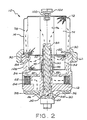
- the flow path of fuel through the filter assembly is illustrated by the arrows in Figure 2.
- fuel is supplied to the inlet passage 52 for traversal through annulus 56 and opening 26 to the heat chamber 28.
- the fuel then flows axially through sleeve 48 in close proximity to heat rod 32 so that the fuel may be heated if required.
- the fuel continues axially upwardly (in the direction of the arrows in Figure 2) into the primary chamber 76 for outward traversal through the primary filter element 74.
- the filter element 74 functions to remove particulate matter from the fuel.
- the particulate matter is entrapped on the upstream side of the primary filter element 74.
- the fuel passes into the coalescing chamber 78 wherein water coalesces as droplets from the fuel and passes along with the fuel through apertures 90.
- the water continues downwardly for collection in the sumps 40 and 42.
- the secondary stage filter is a water barrier which prevents the entry of water into the secondary stage chamber 94.
- the filtered fuel then passes through secondary stage element 92 to the interior chamber 95 for generally axial traversal through passage 49 between sleeves 48 and 50 (as illustrated by the arrows in Figure 2).
- the filtered fuel then flows generally radially out the outlet passage 58 for delivery to the fuel injection pump and/or engine.
- the foregoing fuel filter assembly 10 provides an efficient means for filtering particulate matter from the fuel, for removing water from the fuel and for heating the fuel if required to a sufficient temperature to prevent the precipitation of wax crystals.
- the filter cartridge 14 is disposable so that when the effectiveness of the filter cartridge is expended, a new cartridge may be mounted in place as required.
- the retaining collar 62 is threadably loosened, the releasable air vent 102 is removed from the cartridge element, and a new cartridge is suitably secured in position.
- the installed fuel filter assembly may be inverted, i.e., the cartridge mounted below the base as best illustrated in Figures 9 and 10.
- the fuel filter assembly 10a also principally differs from fuel filter assembly 10 in that the primary and secondary filter elements 74a and 92a essentially function as a dual stage fuel filter without additionally employing an effective provision for removing water from the fuel.
- Components of fuel filter assembly 10a which correspond to those previously described are designated generally by the numerals corresponding to the components of fuel filter assembly 10 followed by the letter "a".
- the fuel enters the fuel filter assembly 10a through fuel inlet passage 52a and exits the filter through outlet passage 58a.
- the general flow path of the fuel through the filter assembly is generally designated by the arrows of Figure 9.
- the fuel flow path is essentially directionally inverted in comparison to the path of Figure 2.
Abstract
Description
- This invention relates generally to devices for filtering and separating liquids. More particularly, the present invention relates to fuel filters for removing foreign particles and separating water from fuel of the fuel supply system of an internal combustion engine.
- The absence of high standards of quality control in diesel fuel supplies dictates that an effective fuel filter be incorporated into the fuel supply system for a diesel engine. It is not uncommon for diesel fuel to have significant quantities of abrasive particles and water. The abrasive particles present the potential for permanent damage to components of the fuel injection pump. The abrasive particles can also adversely effect the performance of the pump by destroying the ability of the fuel injection pump to precisely meter and deliver fuel at high pressures. The presence of water in the diesel fuel supply can cause rusting of engine components, and during freezing conditions, can result in interruption of the fuel injection system and/or seizure of moving components.
- Diesel fuel also contains a waxy constituent which precipitates as wax crystals when the fuel temperature drops below a characteristic "cloud point". In cold weather conditions, the precipitating wax crystals can rapidly plug a fuel filter and thereby cut off fuel delivery to the internal combustion engine.
- A number of conventional fuel filters perform the dual function of removing particulate material from the diesel fuel and separating water from the fuel. In addition, conventional fuel filter units or fuel conditioners frequently employ heaters to prevent wax crystal formation. Commonly, the fuel filters employ a disposable filter cartridge which is replaced at pre-established intervals of filter usage.
- U.S. Patent No. 4,491,120 assigned to the assignee of the present invention, discloses a fuel conditioner to which the present invention relates. A disposable filter/water separator cartridge is releasably secured to a base. A multi-stage filter assembly within the cartridge includes filtering and coalescing media and separates an upper portion of the chamber from a lower portion which functions as a water collection sump. A heater mounted in the base warms the fuel before the fuel enters the cartridge. The fuel conditioner also features sensing devices in the base to indicate the presence of a predetermined quantity of water in the sump and the occurrence of a plugged filter condition. A priming pump is also manually operable to restore the fuel conditioner to operational condition after the cartridge replacement.
- Briefly stated, the invention in a preferred form is a fuel filter assembly which includes a base and a disposable filter cartridge mountable to the base. The base includes a fuel inlet passage, a fuel outlet passage, a central first conduit which interiorly defines a first axial passage communicating with the inlet passage, and a second conduit which surrounds the first conduit and defines a second axial passage which communicates with the outlet passage. The base also forms a sump which collects water separated from the fuel. The cartridge comprises a container-like housing. A primary filter unit enclosed in the housing comprises a pleated primary filter element defining a first chamber which communicates with the first axial passage and a second chamber surrounding the first chamber. A secondary filter element extends exteriorly from the housing. The base and secondary filter element cooperate to define a third chamber and an inner fourth chamber. The fourth chamber is surrounded by the third chamber. The fourth chamber communicates with the second axial passage.
- The first and second axial passages are preferably coaxial. The housing also includes a first endcap and a first sealing grommet surrounding an opening for fluidly sealing the endcap with the first conduit. A second endcap axially spaced from the first endcap mounts a second sealing means for fluidly sealing the second endcap to the second conduit. The secondary filter element is disposed between the first and second endcaps. The first endcap also has a plurality of angularly spaced apertures which provide fluid communication between the second and third chambers.
- A heating unit comprising a heat rod extending axially in the first conduit is employed for heating fuel. The secondary filter element is impervious to the passage of water. The primary filter element contains water coalescing properties which result in the formation of water droplets in the second chamber.
- The inlet passage has an inlet port and the outlet passage has an outlet port. The ports are located at diametrically opposed locations of the base. The sump has a pair of sump sections with the inlet and outlet passages being disposed between the sump sections. A water level sensor is disposed in the sump. A drain cock is also disposed in the sump for draining collected water from the filter assembly.
- A fuel filter cartridge in accordance with the invention includes a container which forms a housing. A continuous fan-shaped, pleated primary filter element is disposed in the housing. The primary filter element has water coalescing properties and defines a central inner region on one side of the element and an outer region on the opposite side of the element. An endcap connects at one end of the housing and encloses the primary element. The endcap defines a central opening. A sealing grommet is mounted in the opening for fluidly sealing a conduit which is received through the opening. A secondary filter element disposed axially from the primary filter element is located exteriorly of the housing. The secondary filter element is impervious to the passage of water and defines a central inner region. A second endcap encloses an axial end of the secondary filter element. The endcap defines a central opening which is coaxial with the first opening. A sealing grommet is received in the second opening for fluidly sealing a second conduit which is received through the second opening. The first endcap has a plurality of angularly spaced apertures. Both the first and second filter elements have a fan-shaped pleated configuration. The first endcap comprises a plate which is bent to form a first shoulder which engages peripheral edge proportions of the first element and a second shoulder of smaller diameter which engages peripheral edge proportions of the second element.
- The first endcap connects with the container housing along a circumferential roll seam. A sealing ring is disposed between the first endcap and an upper shoulder of the base. A retaining collar is threaded to the base and axially engages the top of the roll seam to secure the cartridge to the base and to load the sealing ring.
- An object of the invention is to provide a new and improved fuel filter adaptable for use in filtering the fuel supplied to a diesel engine.
- Another object of the invention is to provide a new and improved fuel filter of efficient low cost construction which provides an effective and efficient means for filtering particulate matter from the fuel and for removing water from the fuel.
- A further object of the invention is to provide a new and improved fuel filter having a disposable cartridge element incorporating a dual stage filter assembly.
- Other objects and advantages of the invention will become apparent from the drawings and the specification.
-
- Figure 1 is an exploded view of a fuel filter assembly in accordance with the present invention;
- Figure 2 is a sectional view of the assembled fuel filter assembly of Figure 1;
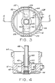
- Figure 3 is a top plan view of the base portion of the fuel filter assembly of Figure 2, said base portion being rotated 90° to the orientation of Figure 2;
- Figure 4 is a cross-sectional view of the base portion taken along the line 4-4 of Figure 3;
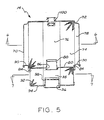
- Figure 5 is a sectional view of the cartridge portion of the fuel filter assembly of Figure 1;
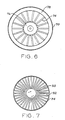
- Figure 6 is a sectional view of the filter cartridge taken along the line 6-6 of Figure 5;
- Figure 7 is a sectional view of the filter cartridge taken along the line 7-7 of Figure 5;
- Figure 8 is an enlarged fragmentary sectional view of the fuel filter assembly of Figure 1;
- Figure 9 is an enlarged fragmentary sectional view of a second embodiment of a fuel filter assembly in accordance with the present invention; and
- Figure 10 is an enlarged fragmentary sectional view of a third embodiment of a fuel filter assembly in accordance with the present invention.
- With reference to the drawings wherein like numerals represent like parts throughout the several figures, a fuel filter assembly in accordance with the present invention is generally designated by the numeral 10.
Fuel filter assembly 10 comprises abase 12 and adisposable filter cartridge 14. The fuel filter assembly is especially adapted for incorporation into the fuel supply system of an internal combustion engine (not illustrated) such as a diesel engine for removing particulate matter from the fuel and for separating water from the fuel. In addition, thefuel filter assembly 10 includes a heater for heating the fuel during cold conditions to prevent the precipitation of wax crystals from the fuel. - The
base 12 rests on aheader endcap 20 which has an opening through which anelectric fuel heater 22 is inserted.Electric fuel heater 22 includes anintegral endcap bolt 24 and anopening 26 which leads to an internal chamber 28. Aheating rod 32 projects axially from thefuel heater bolt 24. The fuel heater contains an intermediate threadedsurface 34 which threads into a complementary threaded portion of thebase 12 for mounting the base to theheader endcap 20. Seal rings 36 and 38 are mounted in annular grooves of the header endcap for sealing the base with the endcap. -
Base 12 is a quasi-cup-like member which includes an interiordiametral shoulder 40. Theshoulder 40 separates the lower portion of the base into a pair ofsumps transverse passage 43 throughshoulder 40 connectssumps bore 46 has a threaded opening at the lower interior portion for threading with theheater element 22. - A
sleeve 48 having an intermediate integral locating ring 51 is closely partially received in a reduced segment of thebore 46. The diameter of the sleeve is greater than the diameter of theheating rod 32 of the heater element and extends in coaxial relationship withrod 32 so as to radially enclose theheating rod 32. The upper segment of thebore 46 has an enlarged diameter. Asecond sleeve 50 is closely received in the enlarged bore portion in concentric relationship withsleeve 48.Sleeve 50 has an intermediateintegral locating ring 53 and has a reduced axial length in comparison to that ofsleeve 48. Thesleeve 50 and its locatingring 53 provide a variable clearance between the base 12 and the cartridge which allows for tolerance buildup. An annularaxial passage 49 is formed betweensleeves Sleeves - A
fuel inlet passage 52 includes a threadedfemale connector 54. The fuel inlet passage extends radially and axially in the shoulder and opens through anannular recess 56 in theendcap 20. Afuel outlet passage 58 extends radially in general alignment withfuel inlet passage 52. An enlarged annulus surrounding theinner sleeve 48 in axial communication with passage 49 (defined betweensleeves 48 and 50) leads to theoutlet passage 58. The fuel outlet passage includes a threadedfemale connection 59 for connecting with an outlet fuel line. - A threaded surface at the upper peripheral portion of the base is configured for threaded engagement with a retaining
collar 62 for securing thedisposable filter cartridge 14 to thebase 12. An uppercircumferential lip 64 of the base receives an O-ring 65 which is engaged by the underside of thecartridge 14. Adrain cock 66 and awater sensor 68 are threaded into the side of the base for interior communication withsump 42. Thewater level sensor 68 electrically communicates with the compartment of the vehicle for indicating that the water level has reached a pre-established level so that the water can be manually drained from the sumps by rotatably loosening thedrain cock 66. - With additional reference to Figure 5, the
disposable filter cartridge 14 comprises a can-like container 70 which is configured to have an upper peripheral recessedindentation 72. A primarystage filter element 74 having a continuous fan-shaped pleated form is received in the container. Thefilter element 74 axially extends slightly below the bottom of the side wall of the container. The primary filter element thus defines an interior centralaxial chamber 76 and quasi-annularouter chamber 78. The primary filter element is affixed with resin binders or other water coalescers so that as the fuel passes from thepassage 76 through thefilter element 74 tochamber 78, the water coalesces to form water droplets in the coalescingchamber 78. - A
primary stage endcap 80 encloses the primary filter element. Theendcap 80 is rolled and fastened against the bottom edge portions of the container to form acircumferential roll seam 81 having an upper retainingshoulder 83. Theendcap 80 is also folded so as to have an innerannular retaining shoulder 82 which engages the lower portion of thefilter element 74 for locating the element. Theendcap 80 also defines at an inner underside location anannular retaining shoulder 84 which is generally coaxial withshoulder 82 and has a smaller diameter thanshoulder 82. A centralcircular opening 86 through the endcap receives anelastomeric sealing element 88 which is dimensioned to fluidly seal againstsleeve 48 upon mounting the filter cartridge to the base. The axially spaced edge portions of theprimary filter element 74 are secured to the upper underside of the container and the upper surface of theendcap 80 by adhesive such as "Plastisol" adhesive. An upper annular platform formed by the endcap at the bottom of the coalescingchamber 78 includes a plurality of angularly spacedapertures 90. The coalesced water droplets drop through theapertures 90 fromchamber 78 and are collected in thesumps - A
secondary filter element 92 having a continuous fan-shaped, pleated configuration extends from the underside surface ofendcap 80. The upper peripheral edges of thefilter element 92 retainably abut againstshoulder 84 of theendcap 80. Asecondary stage endcap 94 encloses the axial end of thefilter element 92.Endcap 94 includes a peripheral flange which is upturned so as to retainably engage the peripheral edges of the filter element. Acircular opening 96 through the central portion of the endcap receives anelastomeric sealing grommet 98. Sealinggrommet 98 is dimensioned and positioned for fluidly sealing against theouter sleeve 50 when the filter cartridge is mounted on the base. Adhesive such as "Plastisol" adhesive is applied to the end portions offilter element 92 for securing the filter element toendcaps - The exterior surfaces of the
secondary filter element 92 function as a water barrier which prevents water passage to thecentral chamber 95 defined betweenendcaps Secondary filter element 92 may be comprised of a porous substance which is saturated with silicon so as to form the exterior water barrier. In the unmounted state such as illustrated in Figures 1 and 5, a substantial portion of the exterior surface offilter element 92 is exposed at the underside of thecontainer 70. - The top cover of
container 70 also includes a circular opening through which avalve body 100 is inserted. Thevalve body 100 is sealed to the container with adhesive. A releasableair vent valve 102 is positionable in the valve body. The air vent valve functions to controllably release air from the interior of the fuel filter. Theair vent valve 102 may be removed from thevalve body 100 and reinserted into the valve body of a new cartridge upon replacement of a spent cartridge. - In practice, the
disposable filter cartridge 14 is mounted to thebase 12 by forcing the cartridge over thesleeves elastomeric grommets respective sleeves endcap 80 engages an elastomeric O-ring 65 which is positioned againstlip 64 of the base. The retainingcollar 62 is then threaded to the base and axially engageable against theroll seam shoulder 83 of thecontainer 70 to compressively load the O-ring 65 and secure the cartridge in a fluid tight relationship with the base. - The
roll seam 81 has a multi-layer configuration which imposes a rigid structure at the endcap/container interface. The O-ring 65 is located in close proximity to theroll seam 81 at a cartridge location having a high degree of structural integrity. A substantial compressive force may thus be exerted against the O-ring through theendcap 80 without jeopardizing the structural or functional integrity of the cartridge. - The only cartridge sealing element which is compressively loaded is O-
ring 65.Grommets sleeves ring 53. - The
lip 64 is preferably inclined (from the inner to outer portions) at a downward angle so that the axial compressive load functions additionally to center the cartridge on the base. The inclined lip configuration also tends to force the O-ring sealing interface radially away from theapertures 90 to insure unobstructed fluid communication therethrough. - The fuel filter assembly may be suitably mounted to the vehicle by means of a
bracket 104 having cooperative shoulders which receive aclamp ring 106. A bolt (not illustrated) extends between aligned openings of the clamp ring and an opening in the bracket for securing the clamp ring to the bracket. Theclamp ring 106 surrounds and clampingly engages a recessedneck 108 of the base for securing the base in position. - The flow path of fuel through the filter assembly is illustrated by the arrows in Figure 2. In operation, fuel is supplied to the
inlet passage 52 for traversal throughannulus 56 andopening 26 to the heat chamber 28. The fuel then flows axially throughsleeve 48 in close proximity to heatrod 32 so that the fuel may be heated if required. The fuel continues axially upwardly (in the direction of the arrows in Figure 2) into theprimary chamber 76 for outward traversal through theprimary filter element 74. Thefilter element 74 functions to remove particulate matter from the fuel. The particulate matter is entrapped on the upstream side of theprimary filter element 74. The fuel passes into the coalescingchamber 78 wherein water coalesces as droplets from the fuel and passes along with the fuel throughapertures 90. The water continues downwardly for collection in thesumps secondary stage chamber 94. - The filtered fuel then passes through
secondary stage element 92 to theinterior chamber 95 for generally axial traversal throughpassage 49 betweensleeves 48 and 50 (as illustrated by the arrows in Figure 2). The filtered fuel then flows generally radially out theoutlet passage 58 for delivery to the fuel injection pump and/or engine. - The foregoing
fuel filter assembly 10 provides an efficient means for filtering particulate matter from the fuel, for removing water from the fuel and for heating the fuel if required to a sufficient temperature to prevent the precipitation of wax crystals. Furthermore, thefilter cartridge 14 is disposable so that when the effectiveness of the filter cartridge is expended, a new cartridge may be mounted in place as required. The retainingcollar 62 is threadably loosened, thereleasable air vent 102 is removed from the cartridge element, and a new cartridge is suitably secured in position. - It should be appreciated that for some applications the installed fuel filter assembly may be inverted, i.e., the cartridge mounted below the base as best illustrated in Figures 9 and 10. With reference to Figure 9, the
fuel filter assembly 10a also principally differs fromfuel filter assembly 10 in that the primary andsecondary filter elements fuel filter assembly 10a which correspond to those previously described are designated generally by the numerals corresponding to the components offuel filter assembly 10 followed by the letter "a". The fuel enters thefuel filter assembly 10a throughfuel inlet passage 52a and exits the filter throughoutlet passage 58a. The general flow path of the fuel through the filter assembly is generally designated by the arrows of Figure 9. The fuel flow path is essentially directionally inverted in comparison to the path of Figure 2. - Fuel filter assembly 10b illustrated in Figure 10 is an inverted fuel filter (as compared to Figures 1 - 5) which also functions as a water separator. The container 70b of the cartridge portion surrounding the primary filter element 74b is elongated to provide a chamber or
sump 120 which is below the primary filter element. Alower endcap 122 is also mounted over the lower axial end of the filter element 74b. The primary filter element 74b has water coalescing properties so that water droplets form at the outlet side of the filter element and fall to the bottom of the sump 120 (as schematically illustrated in Figure 20). Adrain cock 124 is mounted at the bottom of the sump for draining the collected water from the filter. The container 70b may be manufactured from a transparent or translucent material to permit visual inspection of the water level. The general fuel flow path through filter assembly 10b is generally designated by the arrows in Figure 10. - While a preferred embodiment of the foregoing invention has been set forth for purposes of illustration, the forgegoing description should not be deemed a limitation of the invention herein. Accordingly, various modifications, adaptations and alternatives may occur to one skilled in the art without departing from the spirit and the scope of the present invention.
Claims (49)
base means comprising a base forming a lip and having a fuel inlet passage, fuel outlet passage, central first conduit means for interiorly defining a first axial passage communicable with said inlet passage and second conduit means surrounding said first conduit means for defining a second axial passage communicating with said outlet passage;
filter cartridge means mountable to said base means for removing particulate matter and water from fuel, said cartridge means comprising:
housing means comprising a container and a first endcap connected to said container along a circumferential seam forming a retaining shoulder;
first filter means enclosed in said housing means defining a first chamber communicating with said first axial passage and a second chamber surrounding said first chamber;
second filter means comprising a second filter element extending exteriorly of said housing means and defining with said base means a third chamber and a fourth chamber, said third chamber communicating with said second chamber, said fourth chamber communicating with said second conduit passage; and
retainer means comprising a collar threadably engageable with said base means and axially engageable against said seam shoulder for retaining said cartridge means to said base means.
housing means for forming a housing having a first end and an axially spaced second end;
first filter means disposed in said housing comprising a first filter element defining a central inner region on one side of said element and an outer region on the opposing side of said element;
first endcap means connecting said second end to form a circumferential retaining shoulder and enclosing said first filter element, said first endcap means defining a first central opening, first sealing means received in said first opening for fluidly sealing a conduit received through said first opening;
second filter means disposed axially from said primary filter means comprising a second filter element and defining a central inner region;
second endcap means enclosing an axial end of said second filter means, said second endcap means defining a second central opening coaxial with said first opening, and second sealing means received in said second opening for fluidly sealing a second conduit received through said second opening.
base means comprising a base having a fuel inlet passage, a fuel outlet passage, central first conduit means for interiorly defining a first axial passage communicable with said inlet passage and second conduit means surrounding said first conduit means for defining a second axial passage communicating with said outlet passage, said base means comprising a lip;
filter cartridge means mountable on said base means for filtering fuel, said cartridge means comprising:
housing means comprising a container and a first endcap connecting said container along a seam configured to form a retaining shoulder, said first endcap defining first opening means for receiving said first conduit means in fluid tight relationship;
first filter means enclosed in said housing means comprising a first filter element defining a first chamber communicating with said first axial passage and a second chamber surrounding said first chamber;
second filter means comprising a second endcap defining second opening means for receiving said second conduit means in fluid tight relationship and comprising a second filter element generally impervious to the passage of water extending exteriorly of said housing means between said first and second endcaps and defining with said base means a third chamber and a fourth chamber surrounded by said third chamber, said third chamber communicating with said second chamber and said fourth chamber;
sealing means for fluidly sealing said cartridge means to said base means comprising a sealing ring compressively sealable between said lip and said first endcap; and
retainer means comprising a collar threadably engageable with said base means and axially engageable against said seam shoulder for retaining said cartridge to said base means.
housing means for forming a housing having a first end and an axially spaced second end;
first filter means disposed in said housing comprising a first filter element defining a central inner region on one side of said element and an outer region on the opposing side of said element;
retaining shoulder means extending generally radially from said housing means;
first sealing means mounted in said housing and defining an axial opening for diametrally fluidly sealing a conduit received through said first opening; and second sealing means mounted in fixed relationship to said housing means and defining a second axial opening axially spaced from said first sealing means for diametrally fluidly sealing a second conduit received through said second opening.
housing means for forming a housing having a first end and an axially spaced second end;
first filter means disposed in said housing comprising a first filter element defining a central inner region and an outer region;
retaining shoulder means extending outwardly from said housing means for providing a retaining structure;
ring means for defining an annular groove proximate said second end for receiving an O-ring;
first diametral seal means mounted interiorly of said housing means for diametrally fluidly sealing a first conduit axially received in said housing means; and
second diametral seal means mounted in fixed relationship to said housing means and generally coaxial with said first seal means for diametrally fluidly sealing a second conduit.
base means comprising a base having a fuel inlet passage, a fuel outlet passage, central first conduit means for interiorly defining a first axial passage communicatable with said inlet passage and second conduit means surrounding said first conduct means for defining a second axial passage communicating with said outlet passage, said base means comprising sump means for collecting water;
filter cartridge means mountable on said base means for removing particulate matter from fuel, said cartridge means comprising:
housing means;
primary filter means enclosed in said housing means comprising a folded primary filter element defining a first chamber communicating with said first axial passage and a second chamber surrounding said first chamber;
secondary filter means comprising a secondary filter element extending exteriorly of said housing means and defining with said base means a third chamber and a fourth chamber surrounded by said third chamber, said third chamber communicating with and axially disposed between said second chamber and said sump means, said fourth chamber communicating with said second conduit passage.
container means for forming a housing having an at least partially closed first end and axially spaced second end;
primary filter means disposed in said housing comprising a first filter element having water coalescing properties defining a central inner region on one side of said element and an outer region on the opposing side of said element;
first endcap means connecting said second end to and enclosing said first filter element within said housing, said first endcap means defining a first central opening, first sealing means receiving in said first opening for fluidly sealing a conduit received through said first opening;
secondary filter means disposed axially from said primary filter means and exteriorly of said housing comprising a second filter element which is generally impervious to the passage of water therethrough and defining a central inner region;
second endcap means enclosing an axial end of said second filter element, said endcap means defining a second central opening coaxial with said first opening, second seal means received in said second opening for fluidly sealing a second conduit received through said second opening.
base means comprising a base having a fuel inlet passage, a fuel outlet passage, central first conduit means for interiorly defining a first axial passage communicatable with said inlet passage and second conduit means surrounding said first conduit means for defining a second axial passage communicating with said outlet passage, said base means comprising sump means for collecting water;
filter cartridge means mountable on said base means for removing particulate matter and water from fuel, said cartridge means comprising:
housing means comprising a first endcap defining first opening means for receiving said first conduit means in fluid tight relationship;
primary filter means enclosed in said housing means comprising a folded primary filter element defining a first chamber communicating with said first axial passage and a second chamber surrounding said first chamber;
secondary filter means comprising a second endcap defining second opening means for receiving said second conduit means in fluid tight relationship and comprising a secondary filter element which is generally impervious to the passage of water extending exteriorly of said housing means between said first and second endcaps and defining with said base means a third chamber and a fourth chamber surrounded by said third chamber, said third chamber communicating with said second chamber and said sump means, said fourth chamber communicating with said second axial passage.
Applications Claiming Priority (4)
| Application Number | Priority Date | Filing Date | Title |
|---|---|---|---|
| US372645 | 1989-06-28 | ||
| US07/372,645 US4976852A (en) | 1989-06-28 | 1989-06-28 | Fuel filter |
| US07/404,849 US5017285A (en) | 1989-06-28 | 1989-09-08 | Fuel filter and cartridge assembly |
| US404849 | 1989-09-08 |
Publications (3)
| Publication Number | Publication Date |
|---|---|
| EP0405447A2 true EP0405447A2 (en) | 1991-01-02 |
| EP0405447A3 EP0405447A3 (en) | 1991-05-08 |
| EP0405447B1 EP0405447B1 (en) | 1995-08-23 |
Family
ID=27005847
Family Applications (1)
| Application Number | Title | Priority Date | Filing Date |
|---|---|---|---|
| EP90112130A Expired - Lifetime EP0405447B1 (en) | 1989-06-28 | 1990-06-26 | Fuel filter |
Country Status (6)
| Country | Link |
|---|---|
| US (1) | US5017285A (en) |
| EP (1) | EP0405447B1 (en) |
| JP (1) | JPH03157109A (en) |
| KR (1) | KR910001217A (en) |
| DE (1) | DE69021792T2 (en) |
| ES (1) | ES2078272T3 (en) |
Cited By (25)
| Publication number | Priority date | Publication date | Assignee | Title |
|---|---|---|---|---|
| EP0529782A1 (en) * | 1991-08-16 | 1993-03-03 | Stanadyne Automotive Corp. | Dry change fuel filter system |
| EP0607563A2 (en) * | 1992-12-23 | 1994-07-27 | Stanadyne Automotive Corp. | Fuel filter with spring-loaded retention system |
| EP0635296A1 (en) * | 1993-07-09 | 1995-01-25 | FILTERWERK MANN & HUMMEL GMBH | Filter for liquids |
| DE4444934A1 (en) * | 1994-12-16 | 1996-06-27 | Knecht Filterwerke Gmbh | Fuel filter |
| GB2344542A (en) * | 1998-12-11 | 2000-06-14 | Nissan Europ Tech Centre | Fuel filter mounting |
| WO2005118102A1 (en) * | 2004-06-01 | 2005-12-15 | Ufi Filters S.P.A. | Fuel filter for diesel internal combustion engines |
| WO2009095339A1 (en) * | 2008-02-01 | 2009-08-06 | Mann+Hummel Gmbh | Liquid filter, in particular for fuel |
| WO2009149706A2 (en) * | 2008-06-09 | 2009-12-17 | Hengst Gmbh & Co. Kg | Filter for working fluid of an internal combustion engine, and components of such a filter |
| FR2938881A1 (en) * | 2008-11-25 | 2010-05-28 | Filtrauto | Fuel filter for use in fuel tank of fuel supplying device in internal combustion engine of motor vehicle, has vertical pipe whose lower part is provided with lower opening emerging from exterior of chamber and constituting fuel inlet |
| WO2011157535A1 (en) * | 2010-06-14 | 2011-12-22 | Mann+Hummel Gmbh | Filter device, in particular liquid filter |
| RU2478822C1 (en) * | 2011-12-08 | 2013-04-10 | Федеральное государственное бюджетное образовательное учреждение высшего профессионального образования "Пензенская государственная сельскохозяйственная академия" | Combined fuel filter |
| US8535520B2 (en) | 2009-06-16 | 2013-09-17 | Mann + Hummel Gmbh | Three-stage fuel filter |
| WO2014040863A1 (en) * | 2012-09-14 | 2014-03-20 | Hengst Gmbh & Co. Kg | Fuel filter having a water collecting chamber |
| US9108125B2 (en) | 2008-08-18 | 2015-08-18 | Mahle International Gmbh | Filter device |
| US9333448B2 (en) | 2009-09-15 | 2016-05-10 | Mahle International Gmbh | Filter device |
| WO2016146424A1 (en) * | 2015-03-13 | 2016-09-22 | Mann+Hummel Gmbh | Fuel filter insert, and fuel filter comprising a prefilter element and a main filter element and comprising a water separating unit |
| WO2016146426A1 (en) * | 2015-03-13 | 2016-09-22 | Mann+Hummel Gmbh | Fuel filter insert with a prefilter and a main filter element, and fuel filter |
| WO2016146413A1 (en) * | 2015-03-13 | 2016-09-22 | Mann+Hummel Gmbh | Fuel filter comprising a fuel filter insert with a prefilter element and a main filter element |
| CN112004586A (en) * | 2018-04-12 | 2020-11-27 | 康明斯滤清系统知识产权公司 | Chamber type parallel flow double filter |
| US11207620B2 (en) | 2015-08-31 | 2021-12-28 | Cummins Filtration Ip, Inc. | Filter port seal |
| USD958288S1 (en) | 2020-10-09 | 2022-07-19 | Mahle International Gmbh | Filter device |
| US11426687B2 (en) | 2019-06-27 | 2022-08-30 | Mahle International Gmbh | Fuel filter |
| US11452956B2 (en) | 2019-06-27 | 2022-09-27 | Mahle International Gmbh | Fuel filter |
| USD967330S1 (en) | 2019-03-21 | 2022-10-18 | Mahle International Gmbh | Pin for a filter element |
| US11511217B2 (en) | 2020-09-22 | 2022-11-29 | Mahle International Gmbh | Filter and method of fabricating same |
Families Citing this family (59)
| Publication number | Priority date | Publication date | Assignee | Title |
|---|---|---|---|---|
| US5203994A (en) * | 1991-08-16 | 1993-04-20 | Stanadyne Automotive Corp. | Fuel filter retention system |
| US5186829A (en) * | 1991-08-16 | 1993-02-16 | Stanadyne Automotive Corp. | Fuel filter key system |
| US5236579A (en) * | 1991-08-22 | 1993-08-17 | Stanadyne Automotive Corp. | Fuel filter assembly with modular drain bowl |
| WO1993014858A1 (en) * | 1992-01-22 | 1993-08-05 | Allied-Signal Inc. | Quick connect/disconnect liquid filter |
| JP3373597B2 (en) * | 1992-06-18 | 2003-02-04 | スタナダイン・オートモーティヴ・コーポレイション | Fuel filter with internal vent |
| US5397462A (en) * | 1993-08-24 | 1995-03-14 | Matsushita Electric Industrial Co., Ltd. | Filter with laterally removable element and valve means |
| US6113781A (en) | 1993-09-15 | 2000-09-05 | Parker-Hannifin Corporation | Fuel filter with dual flow |
| WO1995007745A1 (en) * | 1993-09-15 | 1995-03-23 | Parker Hannifin Corporation | Fuel filter element |
| US6053334A (en) * | 1993-09-15 | 2000-04-25 | Parker Hannifin Customer Support Inc. | Fuel filter with valve device |
| US5484527A (en) * | 1993-12-13 | 1996-01-16 | Stanadyne Automotive Corp. | Module for filter assembly base |
| US5458767A (en) * | 1994-08-10 | 1995-10-17 | Parker-Hannifin Corporation | Fuel filter assembly with dual filter media and by-pass device |
| US5667678A (en) * | 1995-04-13 | 1997-09-16 | Advanced Performance Technology, Inc. | Plastic fluid filter and method for assembling same |
| US5817234A (en) * | 1995-04-13 | 1998-10-06 | Advanced Performance Technology, Inc. | Fluid filter and method for assembling same |
| US5855780A (en) * | 1996-11-04 | 1999-01-05 | Advanced Performance Technology, Inc. | Fuel filter element with flow actuator |
| US5853575A (en) * | 1996-11-14 | 1998-12-29 | Ashland Technologies, Inc. | Remote mount fuel filter kit with prime maintaining check valve |
| US6146527A (en) * | 1998-04-21 | 2000-11-14 | Parker-Hannifin Corporation | Spin-on filter cartridge with replaceable element |
| US6174438B1 (en) | 1999-10-15 | 2001-01-16 | Parker-Hannifin Corporation | Dual pass fuel filter assembly and element therefor |
| US6616066B2 (en) * | 2000-01-29 | 2003-09-09 | Daimlerchrysler Ag | Injection valve |
| US6379564B1 (en) | 2000-05-08 | 2002-04-30 | Ronald Paul Rohrbach | Multi-stage fluid filter, and methods of making and using same |
| US6328883B1 (en) | 2000-05-31 | 2001-12-11 | Parker-Hannifin Corporation | Fuel filter assembly with priming pump |
| EP2286892B1 (en) * | 2000-08-11 | 2012-10-10 | Roger P. Reid | Keyed system for connection of filter cartridge to filter holder |
| US20110203985A1 (en) * | 2009-08-21 | 2011-08-25 | Omnipure Filter Company, Pllc | Keyed system for connection of filter to filter holder |
| US9314722B2 (en) | 2000-08-11 | 2016-04-19 | Omnipure Filter Company, Inc. | Keyed system for connection of filter cartridge to filter holder |
| US7476314B2 (en) | 2000-08-11 | 2009-01-13 | Reid Roger P | Keyed system for connection of filter cartridge to filter holder |
| DE20101572U1 (en) * | 2001-01-31 | 2002-06-20 | Hengst Walter Gmbh & Co Kg | Liquid filter with ventilation holes |
| DE10220662B4 (en) * | 2002-05-10 | 2005-08-11 | Hydraulik-Ring Gmbh | Filter cartridge for liquid, freeze-risk media, in particular for use in fuel cell vehicles and internal combustion engines, preferably diesel engines |
| US6881334B2 (en) * | 2002-10-31 | 2005-04-19 | Stanadyne Corporation | Eccentric interference retention system for a filter cartridge |
| GB2396313A (en) * | 2002-12-10 | 2004-06-23 | Fleetguard Inc | A filter assembly |
| DE102004025062B4 (en) * | 2004-05-18 | 2006-09-14 | Hydraulik-Ring Gmbh | Freezer-compatible metering valve |
| WO2007041559A2 (en) * | 2005-09-30 | 2007-04-12 | Stanadyne Corporation | Water separation and filtration structure |
| JP4638329B2 (en) * | 2005-11-09 | 2011-02-23 | 株式会社ケーヒン | Gas trap device for gas |
| US20070114170A1 (en) * | 2005-11-18 | 2007-05-24 | Baldwin Filters, Inc. | Fuel filter cartridge apparatus |
| EP1986759A2 (en) * | 2006-01-30 | 2008-11-05 | Donaldson Company, Inc. | Filter arrangement and methods |
| DE102006005108B4 (en) * | 2006-02-04 | 2017-10-12 | Mahle International Gmbh | Cylindrical filter device |
| EP1984619A2 (en) * | 2006-02-07 | 2008-10-29 | Donaldson Company, Inc. | Filter arrangement and methods |
| DE102007004687B4 (en) | 2007-01-25 | 2012-03-01 | Hydraulik-Ring Gmbh | Volume quantity dispensing unit and method for calibrating the pressure output signal volume quantity characteristic |
| US8147691B2 (en) * | 2007-09-21 | 2012-04-03 | Baldwin Filters, Inc. | Filter cartridge housing attachment systems |
| US8496821B2 (en) * | 2007-12-28 | 2013-07-30 | Caterpillar Inc. | Systems and methods for filtering fuel |
| DE102008012780B4 (en) | 2008-03-05 | 2012-10-04 | Hydraulik-Ring Gmbh | exhaust treatment device |
| US20110017649A1 (en) * | 2009-07-24 | 2011-01-27 | Sasur Timothy M | Two stage filter cartridge |
| DE102009035940C5 (en) * | 2009-08-03 | 2017-04-20 | Cummins Ltd. | SCR exhaust treatment device |
| DE102009041298A1 (en) * | 2009-09-15 | 2011-03-24 | Hengst Gmbh & Co. Kg | Fuel filter of an internal combustion engine |
| EP2525891B1 (en) | 2010-01-22 | 2020-10-07 | Donaldson Company, Inc. | Pulse jet air cleaner systems; evacution valve arrangements; air cleaner components; and, methods |
| USD712007S1 (en) | 2010-03-03 | 2014-08-26 | Omnipure Filter Company, Inc. | Filter for liquid |
| CN102781541B (en) | 2010-03-04 | 2016-09-07 | Hydac过滤技术有限公司 | Filter |
| DE102010061222B4 (en) | 2010-12-14 | 2015-05-07 | Cummins Ltd. | SCR exhaust treatment device |
| JP5565328B2 (en) * | 2011-01-25 | 2014-08-06 | 株式会社デンソー | Fuel filter |
| US9157399B2 (en) * | 2011-05-05 | 2015-10-13 | Hamilton Sundstrand Corporation | Fuel filter adapter |
| JP5835966B2 (en) * | 2011-06-28 | 2015-12-24 | ヤマシンフィルタ株式会社 | Breather equipment |
| JP5639615B2 (en) * | 2011-11-07 | 2014-12-10 | トヨタ紡織株式会社 | Oil deterioration control device |
| JP5677268B2 (en) | 2011-11-07 | 2015-02-25 | トヨタ紡織株式会社 | Oil deterioration control device |
| JP6057541B2 (en) * | 2012-05-07 | 2017-01-11 | トヨタ紡織株式会社 | Oil deterioration control device |
| CN104918673B (en) | 2013-01-14 | 2017-05-31 | 康明斯过滤Ip公司 | Cleanable filter |
| WO2014164163A2 (en) * | 2013-03-13 | 2014-10-09 | Illinois Tool Works Inc. | Water separation filter |
| JP6221919B2 (en) * | 2014-04-22 | 2017-11-01 | 京三電機株式会社 | Filter device |
| WO2018075058A1 (en) * | 2016-10-21 | 2018-04-26 | Cummins Filtration Ip, Inc. | Bowl for filter assemblies |
| CN111417776B (en) | 2017-12-05 | 2022-09-09 | 康明斯过滤Ip公司 | Filter assembly, filter element and filter housing |
| CN112973252B (en) * | 2017-12-05 | 2022-11-25 | 康明斯滤清系统知识产权公司 | Integrated flow structure in closed cover |
| WO2020028306A1 (en) * | 2018-07-30 | 2020-02-06 | Shaw Development, Llc | Aqueous fluid filter assembly with aeration mitigation |
Citations (5)
| Publication number | Priority date | Publication date | Assignee | Title |
|---|---|---|---|---|
| FR1321845A (en) * | 1961-04-14 | 1963-03-22 | Fram Corp | Separator for immiscible fluids |
| CA963400A (en) * | 1971-09-29 | 1975-02-25 | Vladimir Rizek | Combination filter and water separator |
| US4477345A (en) * | 1983-01-10 | 1984-10-16 | Stant Inc. | Filter separator with heater |
| WO1984004051A1 (en) * | 1983-04-14 | 1984-10-25 | Racor Industries Inc | Filter assembly |
| DE3444267A1 (en) * | 1984-12-05 | 1986-06-05 | Hengst Walter Gmbh & Co Kg | Liquid filter having a heat-exchanger end piece |
Family Cites Families (21)
| Publication number | Priority date | Publication date | Assignee | Title |
|---|---|---|---|---|
| US2134413A (en) * | 1937-05-20 | 1938-10-25 | Munoz Alfred | Filter assembly |
| US2355373A (en) * | 1942-03-03 | 1944-08-08 | Lewis E Hankison | Apparatus for filtering and dehydrating fluids |
| US2365149A (en) * | 1942-09-22 | 1944-12-19 | Penn Electric Switch Co | Filter and drier |
| US3158571A (en) * | 1958-08-18 | 1964-11-24 | William M Supinger | Multi-stage filter system |
| US3095370A (en) * | 1960-01-21 | 1963-06-25 | Alfred W Krogman | Filter |
| US3144407A (en) * | 1961-04-14 | 1964-08-11 | Fram Corp | Separator for immiscible fluids |
| GB999562A (en) * | 1962-09-11 | 1965-07-28 | Gen Motors Ltd | Filters for liquids |
| US3312350A (en) * | 1964-06-19 | 1967-04-04 | Bendix Corp | Filter assembly sump drain flow regulator |
| US3390778A (en) * | 1966-03-11 | 1968-07-02 | Walker Mfg Co | Two-stage, twist-on type filter assembly |
| US3465883A (en) * | 1967-07-25 | 1969-09-09 | Wix Corp | Fuel-water separator and filter |
| US3586171A (en) * | 1969-05-09 | 1971-06-22 | Tenneco Inc | Combination dual-flow and two-stage filter |
| US3975273A (en) * | 1974-08-29 | 1976-08-17 | Parma Industries, Inc. | Two-stage fluid filter |
| DE2553293C3 (en) * | 1975-11-27 | 1979-11-15 | Daimler-Benz Ag, 7000 Stuttgart | Lubricating oil filter with a filter bowl standing on a filter base |
| US4259097A (en) * | 1979-12-26 | 1981-03-31 | Siemens-Allis, Inc. | Filtering means for arc suppressing gas system |
| US4372847A (en) * | 1980-06-23 | 1983-02-08 | Chicago Rawhide Manufacturing Company | Fuel filter assembly and cartridge |
| FR2487432A1 (en) * | 1980-07-24 | 1982-01-29 | Diry Andre | FILTER FOR SIMULTANEOUS FUEL FILTRATION AND HEATING |
| US4502956A (en) * | 1982-02-24 | 1985-03-05 | Racor Industries, Inc. | Filter assembly |
| US4491120A (en) * | 1983-06-24 | 1985-01-01 | Stanadyne, Inc. | Fuel conditioner |
| US4465595A (en) * | 1983-08-15 | 1984-08-14 | Pall Corporation | Apparatus for assembly and dissassembly of a filter construction |
| US4579657A (en) * | 1984-11-08 | 1986-04-01 | Filmax, Incorporated | Fluid filter and method of construction |
| US4836923A (en) * | 1987-12-23 | 1989-06-06 | Parker Hannifin Corporation | Cartridge and cover assembly for fluid filters |
-
1989
- 1989-09-08 US US07/404,849 patent/US5017285A/en not_active Expired - Lifetime
-
1990
- 1990-06-26 DE DE69021792T patent/DE69021792T2/en not_active Expired - Fee Related
- 1990-06-26 EP EP90112130A patent/EP0405447B1/en not_active Expired - Lifetime
- 1990-06-26 ES ES90112130T patent/ES2078272T3/en not_active Expired - Lifetime
- 1990-06-28 JP JP2168628A patent/JPH03157109A/en active Pending
- 1990-06-28 KR KR1019900009641A patent/KR910001217A/en not_active Application Discontinuation
Patent Citations (5)
| Publication number | Priority date | Publication date | Assignee | Title |
|---|---|---|---|---|
| FR1321845A (en) * | 1961-04-14 | 1963-03-22 | Fram Corp | Separator for immiscible fluids |
| CA963400A (en) * | 1971-09-29 | 1975-02-25 | Vladimir Rizek | Combination filter and water separator |
| US4477345A (en) * | 1983-01-10 | 1984-10-16 | Stant Inc. | Filter separator with heater |
| WO1984004051A1 (en) * | 1983-04-14 | 1984-10-25 | Racor Industries Inc | Filter assembly |
| DE3444267A1 (en) * | 1984-12-05 | 1986-06-05 | Hengst Walter Gmbh & Co Kg | Liquid filter having a heat-exchanger end piece |
Cited By (43)
| Publication number | Priority date | Publication date | Assignee | Title |
|---|---|---|---|---|
| EP0529782A1 (en) * | 1991-08-16 | 1993-03-03 | Stanadyne Automotive Corp. | Dry change fuel filter system |
| US5312546A (en) * | 1991-08-16 | 1994-05-17 | Stanadyne Automotive Corp. | Dry change fuel filter system |
| EP0607563A2 (en) * | 1992-12-23 | 1994-07-27 | Stanadyne Automotive Corp. | Fuel filter with spring-loaded retention system |
| EP0607563A3 (en) * | 1992-12-23 | 1994-08-03 | Stanadyne Automotive Corp. | Fuel filter with spring-loaded retention system |
| EP0635296A1 (en) * | 1993-07-09 | 1995-01-25 | FILTERWERK MANN & HUMMEL GMBH | Filter for liquids |
| US5520801A (en) * | 1993-07-09 | 1996-05-28 | Filterwerk Mann & Hummel Gmbh | Liquid filter |
| DE4444934A1 (en) * | 1994-12-16 | 1996-06-27 | Knecht Filterwerke Gmbh | Fuel filter |
| DE4444934B4 (en) * | 1994-12-16 | 2004-05-13 | Mahle Filtersysteme Gmbh | fuel |
| GB2344542A (en) * | 1998-12-11 | 2000-06-14 | Nissan Europ Tech Centre | Fuel filter mounting |
| GB2344542B (en) * | 1998-12-11 | 2002-04-17 | Nissan Europ Technology Ct Ltd | Fuel filter mounting |
| WO2005118102A1 (en) * | 2004-06-01 | 2005-12-15 | Ufi Filters S.P.A. | Fuel filter for diesel internal combustion engines |
| CN100496667C (en) * | 2004-06-01 | 2009-06-10 | Ufi过滤股份公司 | Fuel filter for diesel internal combustion engines |
| US7708879B2 (en) | 2004-06-01 | 2010-05-04 | Uri Filters S. P. A. | Fuel filter for diesel internal combustion engines |
| WO2009095339A1 (en) * | 2008-02-01 | 2009-08-06 | Mann+Hummel Gmbh | Liquid filter, in particular for fuel |
| WO2009149706A3 (en) * | 2008-06-09 | 2010-03-18 | Hengst Gmbh & Co. Kg | Filter for working fluid of an internal combustion engine, and components of such a filter |
| WO2009149706A2 (en) * | 2008-06-09 | 2009-12-17 | Hengst Gmbh & Co. Kg | Filter for working fluid of an internal combustion engine, and components of such a filter |
| USRE48745E1 (en) | 2008-08-18 | 2021-09-21 | Mahle International Gmbh | Filter device |
| US9108125B2 (en) | 2008-08-18 | 2015-08-18 | Mahle International Gmbh | Filter device |
| US9810373B2 (en) | 2008-08-18 | 2017-11-07 | Mahle International Gmbh | Filter device |
| USRE49531E1 (en) | 2008-08-18 | 2023-05-16 | Mahle International Gmbh | Filter device |
| FR2938881A1 (en) * | 2008-11-25 | 2010-05-28 | Filtrauto | Fuel filter for use in fuel tank of fuel supplying device in internal combustion engine of motor vehicle, has vertical pipe whose lower part is provided with lower opening emerging from exterior of chamber and constituting fuel inlet |
| US8535520B2 (en) | 2009-06-16 | 2013-09-17 | Mann + Hummel Gmbh | Three-stage fuel filter |
| US9333448B2 (en) | 2009-09-15 | 2016-05-10 | Mahle International Gmbh | Filter device |
| US10871133B2 (en) | 2009-09-15 | 2020-12-22 | Mahle International Gmbh | Filter device |
| US10876507B2 (en) | 2009-09-15 | 2020-12-29 | Mahle International Gmbh | Filter device |
| US10279289B2 (en) | 2009-09-15 | 2019-05-07 | Mahle International Gmbh | Filter device |
| US10456721B2 (en) | 2009-09-15 | 2019-10-29 | Mahle International Gmbh | Filter device |
| WO2011157535A1 (en) * | 2010-06-14 | 2011-12-22 | Mann+Hummel Gmbh | Filter device, in particular liquid filter |
| US9486724B2 (en) | 2010-06-14 | 2016-11-08 | Mann+Hummel Gmbh | Filter device, in particular liquid filter |
| RU2478822C1 (en) * | 2011-12-08 | 2013-04-10 | Федеральное государственное бюджетное образовательное учреждение высшего профессионального образования "Пензенская государственная сельскохозяйственная академия" | Combined fuel filter |
| WO2014040863A1 (en) * | 2012-09-14 | 2014-03-20 | Hengst Gmbh & Co. Kg | Fuel filter having a water collecting chamber |
| WO2016146413A1 (en) * | 2015-03-13 | 2016-09-22 | Mann+Hummel Gmbh | Fuel filter comprising a fuel filter insert with a prefilter element and a main filter element |
| WO2016146426A1 (en) * | 2015-03-13 | 2016-09-22 | Mann+Hummel Gmbh | Fuel filter insert with a prefilter and a main filter element, and fuel filter |
| WO2016146424A1 (en) * | 2015-03-13 | 2016-09-22 | Mann+Hummel Gmbh | Fuel filter insert, and fuel filter comprising a prefilter element and a main filter element and comprising a water separating unit |
| US11207620B2 (en) | 2015-08-31 | 2021-12-28 | Cummins Filtration Ip, Inc. | Filter port seal |
| US11883767B2 (en) | 2015-08-31 | 2024-01-30 | Cummins Filtration Ip, Inc. | Filter port seal |
| CN112004586A (en) * | 2018-04-12 | 2020-11-27 | 康明斯滤清系统知识产权公司 | Chamber type parallel flow double filter |
| CN112004586B (en) * | 2018-04-12 | 2022-07-12 | 康明斯滤清系统知识产权公司 | Chamber type parallel flow double filter |
| USD967330S1 (en) | 2019-03-21 | 2022-10-18 | Mahle International Gmbh | Pin for a filter element |
| US11426687B2 (en) | 2019-06-27 | 2022-08-30 | Mahle International Gmbh | Fuel filter |
| US11452956B2 (en) | 2019-06-27 | 2022-09-27 | Mahle International Gmbh | Fuel filter |
| US11511217B2 (en) | 2020-09-22 | 2022-11-29 | Mahle International Gmbh | Filter and method of fabricating same |
| USD958288S1 (en) | 2020-10-09 | 2022-07-19 | Mahle International Gmbh | Filter device |
Also Published As
| Publication number | Publication date |
|---|---|
| ES2078272T3 (en) | 1995-12-16 |
| DE69021792T2 (en) | 1996-01-11 |
| US5017285A (en) | 1991-05-21 |
| EP0405447A3 (en) | 1991-05-08 |
| EP0405447B1 (en) | 1995-08-23 |
| JPH03157109A (en) | 1991-07-05 |
| DE69021792D1 (en) | 1995-09-28 |
| KR910001217A (en) | 1991-01-30 |
Similar Documents
| Publication | Publication Date | Title |
|---|---|---|
| EP0405447B1 (en) | Fuel filter | |
| US5084170A (en) | Fuel filter | |
| US4976852A (en) | Fuel filter | |
| EP0168160B1 (en) | Filter block mounted fuel processor apparatus | |
| EP0442365B1 (en) | Key system for filter assembly | |
| US4298465A (en) | Fuel filter and water separator apparatus | |
| EP0529286B1 (en) | Fuel filter assembly with modular drain bowl and modular bowl assembly | |
| AU719225B2 (en) | Self-evacuating water-separating fuel filter | |
| EP0529782B1 (en) | Dry change fuel filter system | |
| US4491120A (en) | Fuel conditioner | |
| US4437986A (en) | Separating device and cartridge therefor | |
| US4676895A (en) | Fluid flow baffle for fuel processor | |
| US4470301A (en) | Probe and drain assembly for fuel oil/water separator | |
| US4732671A (en) | Diesel fuel filter/water separator | |
| US20020020660A1 (en) | Liquid filter with a drain for residual liquid | |
| JPH0450844B2 (en) | ||
| GB2078536A (en) | Fuel filter assembly and cartridge | |
| US4618423A (en) | Disposable fuel filter/water separator element | |
| US20040140271A1 (en) | Method of and system for fluid purification | |
| JPS59501738A (en) | Oil purification device with separable evaporation and filtration elements | |
| MXPA00006860A (en) | Lubricating oil reconditioning system |
Legal Events
| Date | Code | Title | Description |
|---|---|---|---|
| PUAI | Public reference made under article 153(3) epc to a published international application that has entered the european phase |
Free format text: ORIGINAL CODE: 0009012 |
|
| AK | Designated contracting states |
Kind code of ref document: A2 Designated state(s): DE ES FR GB IT |
|
| PUAL | Search report despatched |
Free format text: ORIGINAL CODE: 0009013 |
|
| AK | Designated contracting states |
Kind code of ref document: A3 Designated state(s): DE ES FR GB IT |
|
| 17P | Request for examination filed |
Effective date: 19911107 |
|
| 17Q | First examination report despatched |
Effective date: 19921119 |
|
| GRAA | (expected) grant |
Free format text: ORIGINAL CODE: 0009210 |
|
| AK | Designated contracting states |
Kind code of ref document: B1 Designated state(s): DE ES FR GB IT |
|
| REF | Corresponds to: |
Ref document number: 69021792 Country of ref document: DE Date of ref document: 19950928 |
|
| ITF | It: translation for a ep patent filed |
Owner name: UFFICIO TECNICO ING. A. MANNUCCI |
|
| ET | Fr: translation filed | ||
| REG | Reference to a national code |
Ref country code: ES Ref legal event code: FG2A Ref document number: 2078272 Country of ref document: ES Kind code of ref document: T3 |
|
| PLBE | No opposition filed within time limit |
Free format text: ORIGINAL CODE: 0009261 |
|
| STAA | Information on the status of an ep patent application or granted ep patent |
Free format text: STATUS: NO OPPOSITION FILED WITHIN TIME LIMIT |
|
| 26N | No opposition filed | ||
| REG | Reference to a national code |
Ref country code: GB Ref legal event code: IF02 |
|
| PGFP | Annual fee paid to national office [announced via postgrant information from national office to epo] |
Ref country code: GB Payment date: 20050613 Year of fee payment: 16 |
|
| PGFP | Annual fee paid to national office [announced via postgrant information from national office to epo] |
Ref country code: FR Payment date: 20050621 Year of fee payment: 16 |
|
| PGFP | Annual fee paid to national office [announced via postgrant information from national office to epo] |
Ref country code: ES Payment date: 20050628 Year of fee payment: 16 |
|
| PGFP | Annual fee paid to national office [announced via postgrant information from national office to epo] |
Ref country code: DE Payment date: 20050822 Year of fee payment: 16 |
|
| PG25 | Lapsed in a contracting state [announced via postgrant information from national office to epo] |
Ref country code: GB Free format text: LAPSE BECAUSE OF NON-PAYMENT OF DUE FEES Effective date: 20060626 |
|
| PG25 | Lapsed in a contracting state [announced via postgrant information from national office to epo] |
Ref country code: ES Free format text: LAPSE BECAUSE OF NON-PAYMENT OF DUE FEES Effective date: 20060627 |
|
| PGFP | Annual fee paid to national office [announced via postgrant information from national office to epo] |
Ref country code: IT Payment date: 20060630 Year of fee payment: 17 |
|
| PG25 | Lapsed in a contracting state [announced via postgrant information from national office to epo] |
Ref country code: DE Free format text: LAPSE BECAUSE OF NON-PAYMENT OF DUE FEES Effective date: 20070103 |
|
| GBPC | Gb: european patent ceased through non-payment of renewal fee |
Effective date: 20060626 |
|
| REG | Reference to a national code |
Ref country code: FR Ref legal event code: ST Effective date: 20070228 |
|
| REG | Reference to a national code |
Ref country code: ES Ref legal event code: FD2A Effective date: 20060627 |
|
| PG25 | Lapsed in a contracting state [announced via postgrant information from national office to epo] |
Ref country code: FR Free format text: LAPSE BECAUSE OF NON-PAYMENT OF DUE FEES Effective date: 20060630 |
|
| PG25 | Lapsed in a contracting state [announced via postgrant information from national office to epo] |
Ref country code: IT Free format text: LAPSE BECAUSE OF NON-PAYMENT OF DUE FEES Effective date: 20070626 |