EP0405226B1 - Non-magnetic stainless steel - Google Patents
Non-magnetic stainless steel Download PDFInfo
- Publication number
- EP0405226B1 EP0405226B1 EP90111130A EP90111130A EP0405226B1 EP 0405226 B1 EP0405226 B1 EP 0405226B1 EP 90111130 A EP90111130 A EP 90111130A EP 90111130 A EP90111130 A EP 90111130A EP 0405226 B1 EP0405226 B1 EP 0405226B1
- Authority
- EP
- European Patent Office
- Prior art keywords
- weight
- blanking
- stainless steel
- iron
- less
- Prior art date
- Legal status (The legal status is an assumption and is not a legal conclusion. Google has not performed a legal analysis and makes no representation as to the accuracy of the status listed.)
- Expired - Lifetime
Links
- 239000010935 stainless steel Substances 0.000 title claims description 38
- 229910001220 stainless steel Inorganic materials 0.000 title claims description 38
- XEEYBQQBJWHFJM-UHFFFAOYSA-N Iron Chemical compound [Fe] XEEYBQQBJWHFJM-UHFFFAOYSA-N 0.000 claims description 38
- 230000005291 magnetic effect Effects 0.000 claims description 29
- 229910000734 martensite Inorganic materials 0.000 claims description 27
- PXHVJJICTQNCMI-UHFFFAOYSA-N Nickel Chemical compound [Ni] PXHVJJICTQNCMI-UHFFFAOYSA-N 0.000 claims description 26
- 239000000956 alloy Substances 0.000 claims description 19
- 229910052742 iron Inorganic materials 0.000 claims description 19
- 229910045601 alloy Inorganic materials 0.000 claims description 17
- 239000011651 chromium Substances 0.000 claims description 16
- 229910052804 chromium Inorganic materials 0.000 claims description 13
- VYZAMTAEIAYCRO-UHFFFAOYSA-N Chromium Chemical compound [Cr] VYZAMTAEIAYCRO-UHFFFAOYSA-N 0.000 claims description 12
- 229910052759 nickel Inorganic materials 0.000 claims description 12
- IJGRMHOSHXDMSA-UHFFFAOYSA-N Atomic nitrogen Chemical compound N#N IJGRMHOSHXDMSA-UHFFFAOYSA-N 0.000 claims description 10
- OKTJSMMVPCPJKN-UHFFFAOYSA-N Carbon Chemical compound [C] OKTJSMMVPCPJKN-UHFFFAOYSA-N 0.000 claims description 8
- 229910052799 carbon Inorganic materials 0.000 claims description 8
- 239000012535 impurity Substances 0.000 claims description 8
- 239000011572 manganese Substances 0.000 claims description 8
- 239000010949 copper Substances 0.000 claims description 7
- 238000000034 method Methods 0.000 claims description 7
- 229910052710 silicon Inorganic materials 0.000 claims description 7
- 239000010703 silicon Substances 0.000 claims description 7
- PWHULOQIROXLJO-UHFFFAOYSA-N Manganese Chemical compound [Mn] PWHULOQIROXLJO-UHFFFAOYSA-N 0.000 claims description 6
- 229910052748 manganese Inorganic materials 0.000 claims description 6
- RYGMFSIKBFXOCR-UHFFFAOYSA-N Copper Chemical compound [Cu] RYGMFSIKBFXOCR-UHFFFAOYSA-N 0.000 claims description 5
- 229910052802 copper Inorganic materials 0.000 claims description 5
- 229910052757 nitrogen Inorganic materials 0.000 claims description 5
- 238000005096 rolling process Methods 0.000 claims 1
- 239000000463 material Substances 0.000 description 23
- 238000003825 pressing Methods 0.000 description 16
- 238000010008 shearing Methods 0.000 description 11
- 241000237858 Gastropoda Species 0.000 description 9
- 238000004519 manufacturing process Methods 0.000 description 8
- 239000000203 mixture Substances 0.000 description 7
- XUIMIQQOPSSXEZ-UHFFFAOYSA-N Silicon Chemical compound [Si] XUIMIQQOPSSXEZ-UHFFFAOYSA-N 0.000 description 6
- 230000015572 biosynthetic process Effects 0.000 description 5
- 230000003247 decreasing effect Effects 0.000 description 4
- 229910000831 Steel Inorganic materials 0.000 description 3
- 238000005520 cutting process Methods 0.000 description 3
- 230000002950 deficient Effects 0.000 description 3
- 229910052739 hydrogen Inorganic materials 0.000 description 3
- 239000001257 hydrogen Substances 0.000 description 3
- 239000000696 magnetic material Substances 0.000 description 3
- 230000005389 magnetism Effects 0.000 description 3
- 239000002994 raw material Substances 0.000 description 3
- 239000010959 steel Substances 0.000 description 3
- 230000009466 transformation Effects 0.000 description 3
- UFHFLCQGNIYNRP-UHFFFAOYSA-N Hydrogen Chemical compound [H][H] UFHFLCQGNIYNRP-UHFFFAOYSA-N 0.000 description 2
- OAICVXFJPJFONN-UHFFFAOYSA-N Phosphorus Chemical compound [P] OAICVXFJPJFONN-UHFFFAOYSA-N 0.000 description 2
- NINIDFKCEFEMDL-UHFFFAOYSA-N Sulfur Chemical compound [S] NINIDFKCEFEMDL-UHFFFAOYSA-N 0.000 description 2
- 238000005452 bending Methods 0.000 description 2
- 239000011575 calcium Substances 0.000 description 2
- 230000000052 comparative effect Effects 0.000 description 2
- 239000002131 composite material Substances 0.000 description 2
- 230000007797 corrosion Effects 0.000 description 2
- 238000005260 corrosion Methods 0.000 description 2
- 238000010894 electron beam technology Methods 0.000 description 2
- 239000011777 magnesium Substances 0.000 description 2
- 230000005415 magnetization Effects 0.000 description 2
- 238000012423 maintenance Methods 0.000 description 2
- 229910052751 metal Inorganic materials 0.000 description 2
- 239000002184 metal Substances 0.000 description 2
- 239000010955 niobium Substances 0.000 description 2
- 229910052698 phosphorus Inorganic materials 0.000 description 2
- 239000011574 phosphorus Substances 0.000 description 2
- 239000011669 selenium Substances 0.000 description 2
- 230000006641 stabilisation Effects 0.000 description 2
- 238000011105 stabilization Methods 0.000 description 2
- 229910052717 sulfur Inorganic materials 0.000 description 2
- 239000011593 sulfur Substances 0.000 description 2
- 239000010936 titanium Substances 0.000 description 2
- OYPRJOBELJOOCE-UHFFFAOYSA-N Calcium Chemical compound [Ca] OYPRJOBELJOOCE-UHFFFAOYSA-N 0.000 description 1
- JPVYNHNXODAKFH-UHFFFAOYSA-N Cu2+ Chemical compound [Cu+2] JPVYNHNXODAKFH-UHFFFAOYSA-N 0.000 description 1
- GYHNNYVSQQEPJS-UHFFFAOYSA-N Gallium Chemical compound [Ga] GYHNNYVSQQEPJS-UHFFFAOYSA-N 0.000 description 1
- FYYHWMGAXLPEAU-UHFFFAOYSA-N Magnesium Chemical compound [Mg] FYYHWMGAXLPEAU-UHFFFAOYSA-N 0.000 description 1
- ZOKXTWBITQBERF-UHFFFAOYSA-N Molybdenum Chemical compound [Mo] ZOKXTWBITQBERF-UHFFFAOYSA-N 0.000 description 1
- BUGBHKTXTAQXES-UHFFFAOYSA-N Selenium Chemical compound [Se] BUGBHKTXTAQXES-UHFFFAOYSA-N 0.000 description 1
- ATJFFYVFTNAWJD-UHFFFAOYSA-N Tin Chemical compound [Sn] ATJFFYVFTNAWJD-UHFFFAOYSA-N 0.000 description 1
- RTAQQCXQSZGOHL-UHFFFAOYSA-N Titanium Chemical compound [Ti] RTAQQCXQSZGOHL-UHFFFAOYSA-N 0.000 description 1
- 238000005299 abrasion Methods 0.000 description 1
- 239000004411 aluminium Substances 0.000 description 1
- 229910052782 aluminium Inorganic materials 0.000 description 1
- XAGFODPZIPBFFR-UHFFFAOYSA-N aluminium Chemical compound [Al] XAGFODPZIPBFFR-UHFFFAOYSA-N 0.000 description 1
- 238000000137 annealing Methods 0.000 description 1
- 229910052787 antimony Inorganic materials 0.000 description 1
- WATWJIUSRGPENY-UHFFFAOYSA-N antimony atom Chemical compound [Sb] WATWJIUSRGPENY-UHFFFAOYSA-N 0.000 description 1
- 229910052785 arsenic Inorganic materials 0.000 description 1
- RQNWIZPPADIBDY-UHFFFAOYSA-N arsenic atom Chemical compound [As] RQNWIZPPADIBDY-UHFFFAOYSA-N 0.000 description 1
- QVGXLLKOCUKJST-UHFFFAOYSA-N atomic oxygen Chemical compound [O] QVGXLLKOCUKJST-UHFFFAOYSA-N 0.000 description 1
- CXOWYMLTGOFURZ-UHFFFAOYSA-N azanylidynechromium Chemical compound [Cr]#N CXOWYMLTGOFURZ-UHFFFAOYSA-N 0.000 description 1
- 229910052797 bismuth Inorganic materials 0.000 description 1
- JCXGWMGPZLAOME-UHFFFAOYSA-N bismuth atom Chemical compound [Bi] JCXGWMGPZLAOME-UHFFFAOYSA-N 0.000 description 1
- 229910052791 calcium Inorganic materials 0.000 description 1
- 239000010941 cobalt Substances 0.000 description 1
- 229910017052 cobalt Inorganic materials 0.000 description 1
- GUTLYIVDDKVIGB-UHFFFAOYSA-N cobalt atom Chemical compound [Co] GUTLYIVDDKVIGB-UHFFFAOYSA-N 0.000 description 1
- 238000005097 cold rolling Methods 0.000 description 1
- 239000003086 colorant Substances 0.000 description 1
- 229910001431 copper ion Inorganic materials 0.000 description 1
- 239000013078 crystal Substances 0.000 description 1
- 238000006477 desulfuration reaction Methods 0.000 description 1
- 230000023556 desulfurization Effects 0.000 description 1
- 230000006866 deterioration Effects 0.000 description 1
- 230000001747 exhibiting effect Effects 0.000 description 1
- 230000005294 ferromagnetic effect Effects 0.000 description 1
- 238000005242 forging Methods 0.000 description 1
- 229910052733 gallium Inorganic materials 0.000 description 1
- 238000000227 grinding Methods 0.000 description 1
- 229910052735 hafnium Inorganic materials 0.000 description 1
- VBJZVLUMGGDVMO-UHFFFAOYSA-N hafnium atom Chemical compound [Hf] VBJZVLUMGGDVMO-UHFFFAOYSA-N 0.000 description 1
- 238000005098 hot rolling Methods 0.000 description 1
- 150000002431 hydrogen Chemical class 0.000 description 1
- 230000006698 induction Effects 0.000 description 1
- 150000002500 ions Chemical class 0.000 description 1
- 229910052749 magnesium Inorganic materials 0.000 description 1
- WPBNNNQJVZRUHP-UHFFFAOYSA-L manganese(2+);methyl n-[[2-(methoxycarbonylcarbamothioylamino)phenyl]carbamothioyl]carbamate;n-[2-(sulfidocarbothioylamino)ethyl]carbamodithioate Chemical compound [Mn+2].[S-]C(=S)NCCNC([S-])=S.COC(=O)NC(=S)NC1=CC=CC=C1NC(=S)NC(=O)OC WPBNNNQJVZRUHP-UHFFFAOYSA-L 0.000 description 1
- 238000002844 melting Methods 0.000 description 1
- 230000008018 melting Effects 0.000 description 1
- 238000002156 mixing Methods 0.000 description 1
- 229910052750 molybdenum Inorganic materials 0.000 description 1
- 239000011733 molybdenum Substances 0.000 description 1
- 229910052758 niobium Inorganic materials 0.000 description 1
- GUCVJGMIXFAOAE-UHFFFAOYSA-N niobium atom Chemical compound [Nb] GUCVJGMIXFAOAE-UHFFFAOYSA-N 0.000 description 1
- 229910052760 oxygen Inorganic materials 0.000 description 1
- 239000001301 oxygen Substances 0.000 description 1
- 230000002093 peripheral effect Effects 0.000 description 1
- 230000035699 permeability Effects 0.000 description 1
- 238000004080 punching Methods 0.000 description 1
- VSZWPYCFIRKVQL-UHFFFAOYSA-N selanylidenegallium;selenium Chemical compound [Se].[Se]=[Ga].[Se]=[Ga] VSZWPYCFIRKVQL-UHFFFAOYSA-N 0.000 description 1
- 229910052711 selenium Inorganic materials 0.000 description 1
- 239000007787 solid Substances 0.000 description 1
- 239000000126 substance Substances 0.000 description 1
- JBQYATWDVHIOAR-UHFFFAOYSA-N tellanylidenegermanium Chemical compound [Te]=[Ge] JBQYATWDVHIOAR-UHFFFAOYSA-N 0.000 description 1
- 229910052714 tellurium Inorganic materials 0.000 description 1
- PORWMNRCUJJQNO-UHFFFAOYSA-N tellurium atom Chemical compound [Te] PORWMNRCUJJQNO-UHFFFAOYSA-N 0.000 description 1
- 229910052719 titanium Inorganic materials 0.000 description 1
- WFKWXMTUELFFGS-UHFFFAOYSA-N tungsten Chemical compound [W] WFKWXMTUELFFGS-UHFFFAOYSA-N 0.000 description 1
- LEONUFNNVUYDNQ-UHFFFAOYSA-N vanadium atom Chemical compound [V] LEONUFNNVUYDNQ-UHFFFAOYSA-N 0.000 description 1
Images

Classifications
-
- C—CHEMISTRY; METALLURGY
- C22—METALLURGY; FERROUS OR NON-FERROUS ALLOYS; TREATMENT OF ALLOYS OR NON-FERROUS METALS
- C22C—ALLOYS
- C22C38/00—Ferrous alloys, e.g. steel alloys
- C22C38/18—Ferrous alloys, e.g. steel alloys containing chromium
- C22C38/40—Ferrous alloys, e.g. steel alloys containing chromium with nickel
Definitions
- the present invention relates to precision parts made of non-magnetic stainless steel having excellent workability, and particularly to non-magnetic stainless steel which permits an increase in the life of a mold used in machine working and an improvement in the quality of the precision parts produced by working.
- the invention also relates to a method of producing a television set beam guide part and to said part.
- small precision parts such as non-magnetic gears and the like are mounted in domestic electrical equipment such as television and video tape recorder (VTR), computers, magnetic recording devices, electronic equipment and the like.
- VTR television and video tape recorder
- small oval-shaped beam guide parts each of which has a length of 15 mm, a width of 5 mm and a thickness of 2 mm and which are laminated in multiple stages, are mounted in an electron gun used for color television cathode ray tubes (CRT).
- CTR color television cathode ray tubes
- Such electron guns are generally used for attracting or repulsing the thermions emitted from the cathode of an electrode heated by a heater, converging them to a narrow beam or diffusing them to a wide beam when the thermions are passed through beam guide parts so as to apply them to a predetermined fluorescent surface of a cathode ray tube and to emit light.
- Each of color television cathode ray tubes is equipped with three electron guns for the primary colors, i.e., red, blue and green, and three through holes are formed in parallel in each of the beam guide parts in the axial direction thereof.
- Each of the beam guide parts is made of a non-magnetic material for the purpose of preventing any disturbance of an electron beam from being produced by magnetization with the passage of time.
- Conventional beam guide parts are formed by, for example, blanking out them from a plate of 18-8 stainless steel which consists of an alloy containing 8.0 to 8.3 wt% of Ni, 18 to 19 wt% of Cr, 0.05 to 0.08 wt% of C, 0.8 to 1.0 wt% of Si and 1.0 to 1.4 wt% of Mn and then forming the three through holes by punching the plate.
- the document US-A 4,246,047 discloses a non-magnetic stainless steel for a spring comprising at most 0.2 % of carbon, at most 3 % of manganese, at most 0.045 % of phosphorus, at most 0.03 % of sulfur, at most 1 % of silicon, 18 to 20 % of chromium 8 to 12 % of nickel, 0.08 to 0.25 % of nitrogen and the balance being iron and having a high strength.
- no measures are mentioned to obtain a specific martensitic area ratio in the structure of the solid obtained from processing said components of the steel.
- each of the through holes Since the diameter of each of the through holes is thus relatively decreased, it is difficult to focus the electron rays passing through the through holes and increase the luminance of a cathode ray tube.
- the present invention has been achieved for solving the above problems, and it is an object of the present invention to provide a precision part which is made of a non-magnetic stainless steel which facilitates maintenance and control during working and which causes a significant increase in the life of the mold used and the formation of products showing a narrow scatter in quality.
- the invention concerns a precision part formed by blanking work and made of a non-magnetic stainless steel having excellent workability in accordance with claim 1.
- the invention also concerns a television set beam guide part as claimed in claim 6.
- the invention also concerns a method of producing a television set beam guide part as claimed in claim 7.
- the non-magnetic stainless steel for the precision parts of the present invention consists of an iron-based alloy containing 9 to 22% by weight of nickel, 12 to 26% by weight of chromium, the balance of iron and inevitable impurities, as well as optionally 50 to 5000 ppm of nitrogen, optionally of 0.1 wt.% or less of carbon and 1 wt % or less of silicon and optionally of 10 wt % or less of manganese the ratio of the martensite area in the iron-based alloy structure being 20% or less.
- the television set beam guide part of the present invention is made of the above non-magnetic stainless steel.
- non-magnetic stainless steel referred to herein means stainless steel having permeability of 1.1 or less, more preferably 1.05 or less.
- the inventors first investigated the cause of the occurrence of defective products when precision parts are produced by strong working such as blanking, bending, drawing or the like using as a raw material conventional non-stainless steel.
- the inventors continuously observed the operational state of the pressing system 3 shown in Fig. 2 when a beam guide part 1 having three through holes 2, as shown in Fig. 1, is formed by blanking in the use of the pressing system 3.
- the pressing system 3 for producing beam guide parts is constructed by a set of three pressing machines 3a and comprises, as shown in Fig. 2, a die 4 serving as a mold, a punch 5 having a sharp cutting edge, which is formed in the periphery at the end thereof, and a stopper plate 7 for holding a material 6 to be worked for which is placed on the die 4.
- the beam guide part 1 is manufactured in accordance with three working steps. In each of the steps, the part is cut out from the material 6 to be worked for when the material 6 is subjected to the shearing force of the punch 5 while being fixed on the die 4.
- the through holes 2 are made by blanking the material 6 by utilizing a first pressing machine 3a.
- the through holes 2 are blanked again by using a second pressing machine 3a so that inner surfaces of the through holes 2 are shaved so as to have predetermined inside diameter.
- the material 6 is blanked at a peripheral edge portion enclosing the through holes 2 by using a third pressing machine 3a to form a beam guide part 1.
- the inventors also found that the wear and damage of the punch 5 or the die 4 were caused by the adhesion of the slug 10 to the punch 5 or the die 4, and first confirmed that the adhesion of the slug 10 was based on that the slug 10 had become a ferromagnetic substance. That is, it was confirmed that the magnetized slugs 10 should be adhered to the punch 5 or the die 4 which had been magnetized by a leakage magnetic field leaked from motors for driving the pressing system 3. It was also confirmed that although 18-8 stainless steel essentially had no magnetism, it was magnetized by strong working such as blanking. As a result of observation of the structure of the material 6 to be worked for before and after blanking, it was first found that part of the austenitic structure was transformed to the martensitic structure, and the formation of the martensitic structure caused magnetization.
- the martensitic transformation was easily observed in not only the blanking process but also processes with high working ratios such as bending, drawing process and the like.
- the inventors also confirmed that, although the rate of- the martensite formation in non-magnetic stainless steel depended upon the working ratio, it varied within the range of 30 to 90% in any cases.
- the inventors found that the yield of products can be significantly increased by preventing the martensitic transformation in the material used as much as possible.
- the inventors also found that non-magnetic stainless steel exhibiting both satisfactory workability and quality, as compared with conventional materials, could be produced by adjusting the composition within an appropriate range so as to set the ratio of the martensitic transformation to a value within an appropriate range.
- the present invention was achieved on the basis of these findings.
- the non-magnetic stainless steel used in accordance with the present invention is characterized in that the iron-based alloy structure containing 9 to 22% by weight of nickel, 12 to 26% by weight of chromium, the balance of iron and inevitable impurities has a ratio of the martensitic area of 20% or less.
- the content of Cu contained as inevitable impurities in the iron-based alloy is set to 0.15 wt% or less.
- the television set beam guide part in accordance with the present invention can be obtained by blanking an iron-based alloy plate having the above composition.
- the iron-based alloy plate having the above composition has a ratio of the martensitic area of about 0 to 15%. Even if the iron-based alloy plate is subjected to strong working such as blanking or the like at room temperature, since the ratio of the martensitic area after working is suppressed to 20% or less, the parts produced are hardly magnetized, and the blanking operation can be stably continued. Thus, the non-magnetic beam guide parts can be effectively produced.
- Nickel (Ni) contributes to the stabilization of the austenitic structure, which is soft and forms the more stable austenitic structure at room temperature together with chromium (Cr) or the other elements described below which accelerate the austenitic structure. If the nickel content is as low as less than 9%, the intended good blanking quality cannot be obtained, while if the nickel content exceeds 22%, the strength is decreased, and the heights of the burrs produced after shearing are extremely increased or the smoothness of the material is deteriorated.
- the nickel content is therefore set to a value within the range of 9 to 22% by weight, preferably 10 to 20% by weight, more preferably 11 to 16% by weight.
- Chromium (Cr) is a basic element of stainless steel. If the chromium content is as low as less than 12%, the characteristics of stainless steel cannot be obtained, while if the content exceeds 26%, the workability is deteriorated, and the ratio of martensitic structure after shearing is increased due to an increase in the ratio of the ferritic structure, resulting in an increase in magnetism.
- the chromium content is therefore set to a value within the range of 12 to 26% by weight, preferably 15 to 20% by weight, more preferably 16 to 19% by weight.
- Carbon (C) is an element which contributes to an increase in strength. If the carbon content exceeds 0.1%, the deformation resistance during the shearing work is increased, and the life of the mold is thus decreased.
- the carbon content is therefore set to a value of 0.1% by weight or less, preferably 0.08% by weight, more preferably 0.03% by weight.
- Silicon (Si) is an element which contributes to deoxidation. If the silicon content exceeds 1%, the workability is deteriorated.
- the silicon content is set to a value of not more than 1% by weight, preferably not more than 0.8% by weight, more preferably not more than 0.5% by weight.
- Manganese (Mn) is an element which contributes to the stabilization of the austenitic structure, deoxidation and desulfurization. If the manganese content exceeds 10% by weight, the corrosion resistance is deteriorated.
- the manganese content is set to a value of not more than 10% by weight, preferably not more than 2% by weight, more preferably not more than 1% by weight.
- the non-magnetic stainless steel of the present invention may contain small amounts of elements such as phosphorus (P), sulfur (S) and the like other than the above elements for the purpose of improving the mechanical properties, corrosion resistance or machinability, without producing any problem.
- elements such as phosphorus (P), sulfur (S) and the like other than the above elements for the purpose of improving the mechanical properties, corrosion resistance or machinability, without producing any problem.
- the stainless steel used contains 0 to about 0.4% of copper (Cu) which is inevitably mixed therein in the production process.
- copper easily generates copper ion and the ion has a serious influence on a fluorescent material provided on the fluorescent screen of the cathode ray tube, and copper creates the danger of damaging the cathode ray tube. It is therefore necessary that the copper content of the part material used for television electron guns is suppressed to 0.15% or less.
- the stainless steel may contain other impurities such as antimony (Sb), arsenic (As), tin (Sn), lead (Pb), zinc (Zn), gallium (Ga), bismuth (Bi), selenium (Se) and tellurium (Te) for the purpose of improving the mechanical properties.
- impurities such as antimony (Sb), arsenic (As), tin (Sn), lead (Pb), zinc (Zn), gallium (Ga), bismuth (Bi), selenium (Se) and tellurium (Te) for the purpose of improving the mechanical properties.
- the content of aforementioned impurities is set to a value of not more than 0.5% by weight, more preferably not more than 0.1% by weight so as not to deteriorate hot workability in the production process.
- Elements such as cobalt (Co), vanadium (V), titanium (Ti), aluminium (Al), zirconium (Zr), niobium (Nb) and hafnium (Hf) may be added at an amount of not more than 1% by weight, preferably not more than 0.5% by weight, more preferably not more than 0.1% by weight, so as not to deteriorate the workability.
- Elements such as wolfram (W) and molybdenum (Mo) may be added at an amount of not more than 1.0% by weight, preferably not more than 0.5% by weight, so as to stabilize the ferritic structure.
- W wolfram
- Mo molybdenum
- hydrogen (H) creates hydrogen embrittlement
- hydrogen content is suppressed to 0.01% or less, preferably 0.005% by weight.
- Oxygen (O), magnesium (Mg) and calcium (Ca) will deteriorate workability of blanking due to the formation of a non-metallic inclusion, so the content of these elements is suppressed to 0.01% or less, preferably 0.005% or less.
- an attempt can be made to stabilize the austenitic structure and increase the strength by adding nitrogen(N)-containing chromium, chromium nitride or the like so as to regulate the N content in the alloy to 50 to 5000 ppm.
- the occurrence of sags and burrs in a part having a thin blanked portion can be reduced.
- the N content is preferably within the range of 100 to 2000 ppm, more preferably 150 to 1000 ppm.
- the ratio of the martensitic area is calculated by determining the ratio of the martensitic area to the total area of each of at least ten test sectional areas which are selected in the vicinity of the working surface and calculating the average of the ratios.
- the ratio of the martensitic area significantly affects the magnetism of the material. Namely, if the martensitic area ratio exceeds 20%, the iron-based alloy material is easily magnetized after working and creates the above problems. For example, the slug produced during shearing thus easily adheres to the mold and/or the raw material which are to be magnetized, and causes a damage of the mold or products and causes a decrease in the yield of products.
- the martensitic area ratio is therefore set to a value of 20% or less.
- the martensitic area ratio of the non-magnetic stainless steel, which contains Ni and Cr within the above composition ranges and which is prepared in accordance with an ordinary production process, is 0 to about 10%.
- the ratio of the martensitic area can be suppressed to 20% or less even after the working.
- the ratio of the martensitic area can be determined by, for example, photographing the structure by a metal microscope with a magnification of about 400, measuring the total area and the martensitic area and calculating the ratio therebetween.
- a metal raw material which was prepared by mixing the components shown in each of Examples 1 to 10 in the left column of Table 1, was melted in a highfrequency induction vacuum melting furnace and then cast to form a cast ingot which was then heated at 1150 to 1250°C and subjected to hot forging. The ingot was further heated at 1150 to 1250°C and then subjected to hot rolling. The products were then subjected to solution annealing and cold rolling with the final working ratio to obtain a plate having a thickness of 2 mm.
- the thus-formed plate was placed in the pressing system shown in Fig. 2 and then subjected to continuous blanking at room temperature to produce the electron gun beam guide part shown in Fig. 1.
- the martensitic area ratio in the shearing surface was measured, and the number of times of blanking, which was continuously performed until a slug had serious influences on the pressing system or the products by the shearing work or until no good blanked part could be obtained owing to the progress of abrasion of the mold, was measured.
- the results obtained are shown in the right column of Table 1.
- the non-magnetic stainless steel having excellent workability used in the present invention exhibits a low martensitic area ratio and a number of times of continuous blanking which is increased about 2 to 10 times, as compared with the conventional non-magnetic materials shown in Comparative Examples 1 to 6. It is therefore possible to significantly decrease the number of times of re-grinding of the mold and significantly increase the production efficiency of precision parts.
- the toughness is improved by the Ni contained in the steel, and the deformation resistance during working is low because of the low carbon content, no fracture surface is formed by cracks, and a precision part having a smooth shearing surface and few burrs can be obtained at all times. There is thus no need for post-finishing of the fracture surface, and precision parts having high quality and high dimensional precision can be stably produced.
- the grain size of each of the part materials prepared in Examples 1 to 10 was within the range of grain size numbers 7 to 9. There is a tendency that, an increase in grain size number causes a decrease in grain size, hardening of the crystal, and the extension of the fracture surface produced during blanking. In order to obtain a precision part having a smooth shearing surface in this embodiment, it is therefore preferable to prepare a material so that the grain size number is within the range of 8.0 to 8.5.
- This embodiment concerns the examples in which a precision part was formed by singly using the alloy material having each of the compositions shown in Table 1.
- a specification plate material such as conventional 18-8 stainless steel, SUS304 or the like to form a composite material which was then subjected to blanking
- the part produced exhibits the same excellent blanking quality.
- ratio of the thickness of the conventional stainless steel to the total thickness of the composite material is preferably 2 to 20%, more preferably 5 to 15%.
- the non-magnetic stainless steel having excellent workability used in the present invention shows a low deformation resistance during working and has no serious influence caused by slugs produced during blanking, as compared with conventional non-magnetic materials. Further, since the non-magnetic stainless steel of the present invention has a stable structure and is not magnetized, slugs do no adhere to the mold and the plate material. The non-magnetic stainless steel therefore permits a significant increase in the life of the mold used, the stable production of precision parts of high quality and a significant improvement in the efficiency of production of precision parts by strong working such as blanking or the like.
Landscapes
- Chemical & Material Sciences (AREA)
- Engineering & Computer Science (AREA)
- Materials Engineering (AREA)
- Mechanical Engineering (AREA)
- Metallurgy (AREA)
- Organic Chemistry (AREA)
- Punching Or Piercing (AREA)
- Heat Treatment Of Steel (AREA)
- Heat Treatment Of Sheet Steel (AREA)
- Soft Magnetic Materials (AREA)
- Forging (AREA)
Description
- The present invention relates to precision parts made of non-magnetic stainless steel having excellent workability, and particularly to non-magnetic stainless steel which permits an increase in the life of a mold used in machine working and an improvement in the quality of the precision parts produced by working. The invention also relates to a method of producing a television set beam guide part and to said part.
- Many small precision parts such as non-magnetic gears and the like are mounted in domestic electrical equipment such as television and video tape recorder (VTR), computers, magnetic recording devices, electronic equipment and the like. For example, small oval-shaped beam guide parts, each of which has a length of 15 mm, a width of 5 mm and a thickness of 2 mm and which are laminated in multiple stages, are mounted in an electron gun used for color television cathode ray tubes (CRT).
- Such electron guns are generally used for attracting or repulsing the thermions emitted from the cathode of an electrode heated by a heater, converging them to a narrow beam or diffusing them to a wide beam when the thermions are passed through beam guide parts so as to apply them to a predetermined fluorescent surface of a cathode ray tube and to emit light. Each of color television cathode ray tubes is equipped with three electron guns for the primary colors, i.e., red, blue and green, and three through holes are formed in parallel in each of the beam guide parts in the axial direction thereof. Each of the beam guide parts is made of a non-magnetic material for the purpose of preventing any disturbance of an electron beam from being produced by magnetization with the passage of time.
- Conventional beam guide parts are formed by, for example, blanking out them from a plate of 18-8 stainless steel which consists of an alloy containing 8.0 to 8.3 wt% of Ni, 18 to 19 wt% of Cr, 0.05 to 0.08 wt% of C, 0.8 to 1.0 wt% of Si and 1.0 to 1.4 wt% of Mn and then forming the three through holes by punching the plate.
- When small beam guide parts used for television sets are produced by blanking out from 18-8 stainless steel, which is a general material, however, since the mold or the pressing part of a pressing system is easily damaged or broken off, the part products are damaged or broken. There is thus a problem in that the quality of the products is deteriorated, and the yield of the products is significantly decreased.
- In the conventional blanking process, the operator must conduct a troublesome work of constantly checking the occurrence of defective products. In a stage where defective products easily occur, the operation is stopped, and the mold is polished again.
- There are thus disadvantages in that, since the substantial life of the mold is short, the operation cannot be continued for a long period, and the production efficiency is low, and in that the maintenance, control and checking works require a great deal of labor.
- The document US-A 4,246,047 discloses a non-magnetic stainless steel for a spring comprising at most 0.2 % of carbon, at most 3 % of manganese, at most 0.045 % of phosphorus, at most 0.03 % of sulfur, at most 1 % of silicon, 18 to 20 % of
chromium 8 to 12 % of nickel, 0.08 to 0.25 % of nitrogen and the balance being iron and having a high strength. In said document, no measures are mentioned to obtain a specific martensitic area ratio in the structure of the solid obtained from processing said components of the steel. - In particular, when beam guide parts for television sets are produced by using conventional materials, the materials have poor blanking quality and a tendency to be greatly deformed. It is therefore necessary for preventing the deformation to increase the distance between the through holes formed in each part body.
- Since the diameter of each of the through holes is thus relatively decreased, it is difficult to focus the electron rays passing through the through holes and increase the luminance of a cathode ray tube.
- The present invention has been achieved for solving the above problems, and it is an object of the present invention to provide a precision part which is made of a non-magnetic stainless steel which facilitates maintenance and control during working and which causes a significant increase in the life of the mold used and the formation of products showing a narrow scatter in quality.
- It is another object of the present invention to provide a television set beam guide part which can be easily produced by using the above non-magnetic stainless steel with good blanking quality and which permits a significant increase in luminance of a television set.
- The invention concerns a precision part formed by blanking work and made of a non-magnetic stainless steel having excellent workability in accordance with
claim 1. - The invention also concerns a television set beam guide part as claimed in
claim 6. - The invention also concerns a method of producing a television set beam guide part as claimed in
claim 7. - The non-magnetic stainless steel for the precision parts of the present invention consists of an iron-based alloy containing 9 to 22% by weight of nickel, 12 to 26% by weight of chromium, the balance of iron and inevitable impurities, as well as optionally 50 to 5000 ppm of nitrogen, optionally of 0.1 wt.% or less of carbon and 1 wt % or less of silicon and optionally of 10 wt % or less of manganese the ratio of the martensite area in the iron-based alloy structure being 20% or less.
- The television set beam guide part of the present invention is made of the above non-magnetic stainless steel. The terms "non-magnetic stainless steel" referred to herein means stainless steel having permeability of 1.1 or less, more preferably 1.05 or less.
- In the accompanying drawing:
- Fig. 1 is a perspective view of an example of the shape of a precision part;
- Fig. 2 is a sectional view of an embodiment of a pressing apparatus for blanking out a precision part; and
- Fig. 3 is a perspective view which shows the cut surface of a precision part and a slug.
- To achieve the above objects, the inventors first investigated the cause of the occurrence of defective products when precision parts are produced by strong working such as blanking, bending, drawing or the like using as a raw material conventional non-stainless steel.
- The inventors continuously observed the operational state of the
pressing system 3 shown in Fig. 2 when abeam guide part 1 having three throughholes 2, as shown in Fig. 1, is formed by blanking in the use of thepressing system 3. - The
pressing system 3 for producing beam guide parts is constructed by a set of threepressing machines 3a and comprises, as shown in Fig. 2, adie 4 serving as a mold, apunch 5 having a sharp cutting edge, which is formed in the periphery at the end thereof, and astopper plate 7 for holding amaterial 6 to be worked for which is placed on thedie 4. Thebeam guide part 1 is manufactured in accordance with three working steps. In each of the steps, the part is cut out from thematerial 6 to be worked for when thematerial 6 is subjected to the shearing force of thepunch 5 while being fixed on thedie 4. - That is, first, the
through holes 2 are made by blanking thematerial 6 by utilizing a first pressingmachine 3a. Second, the throughholes 2 are blanked again by using a secondpressing machine 3a so that inner surfaces of the throughholes 2 are shaved so as to have predetermined inside diameter. Thirdly, thematerial 6 is blanked at a peripheral edge portion enclosing the throughholes 2 by using a third pressingmachine 3a to form abeam guide part 1. - At the step of shaving the
holes 2 by using the second pressing machine, as shown in Fig. 3, formation of ring-shaped slugs 10 and dropping off of theslugs 10 from thedie 4 were observed. - As a result of observation made by the inventors over a long time, at the stage of about 1500 to 5000 times of blanking, the cutting ability of the
punch 5 was deteriorated, and the cutting edge was worn out, with the die 4 serving as a mold being damaged and broken off. As shown in Fig. 3, asmooth shear plane 8 was formed in the upper portion of the side of thebeam guide part 1 and upper portion of the inside surface of the throughholes 2, and a fracture surface was formed in the lower portion of the side due to the occurrence of cracks, which was caused by blanking. Small burrs frequently occurred in the fracture surface, and the ring-shaped slug shown in Fig. 3 was formed after several pressing operations had been further performed and theslugs 10 remained on thepunch 5 and die 4 without falling off. This damage -of precision part products consequently caused the deterioration in quality of the parts and a significant decrease in the yield thereof. - The inventors also found that the wear and damage of the
punch 5 or thedie 4 were caused by the adhesion of theslug 10 to thepunch 5 or thedie 4, and first confirmed that the adhesion of theslug 10 was based on that theslug 10 had become a ferromagnetic substance.
That is, it was confirmed that themagnetized slugs 10 should be adhered to thepunch 5 or thedie 4 which had been magnetized by a leakage magnetic field leaked from motors for driving thepressing system 3. It was also confirmed that although 18-8 stainless steel essentially had no magnetism, it was magnetized by strong working such as blanking. As a result of observation of the structure of thematerial 6 to be worked for before and after blanking, it was first found that part of the austenitic structure was transformed to the martensitic structure, and the formation of the martensitic structure caused magnetization. - The martensitic transformation was easily observed in not only the blanking process but also processes with high working ratios such as bending, drawing process and the like. The inventors also confirmed that, although the rate of- the martensite formation in non-magnetic stainless steel depended upon the working ratio, it varied within the range of 30 to 90% in any cases.
- The inventors found that the yield of products can be significantly increased by preventing the martensitic transformation in the material used as much as possible. The inventors also found that non-magnetic stainless steel exhibiting both satisfactory workability and quality, as compared with conventional materials, could be produced by adjusting the composition within an appropriate range so as to set the ratio of the martensitic transformation to a value within an appropriate range. The present invention was achieved on the basis of these findings.
- The non-magnetic stainless steel used in accordance with the present invention is characterized in that the iron-based alloy structure containing 9 to 22% by weight of nickel, 12 to 26% by weight of chromium, the balance of iron and inevitable impurities has a ratio of the martensitic area of 20% or less.
- It is preferable to mix 50 to 5000 ppm of nitrogen, 0.1 wt% or less of carbon, 1 wt% or less of silicon and 10 wt% of manganese with the above iron-based alloy.
- When the non-magnetic stainless steel is used for electron beam guide parts of a television electron gun, it is preferable that the content of Cu contained as inevitable impurities in the iron-based alloy is set to 0.15 wt% or less.
- The television set beam guide part in accordance with the present invention can be obtained by blanking an iron-based alloy plate having the above composition. The iron-based alloy plate having the above composition has a ratio of the martensitic area of about 0 to 15%. Even if the iron-based alloy plate is subjected to strong working such as blanking or the like at room temperature, since the ratio of the martensitic area after working is suppressed to 20% or less, the parts produced are hardly magnetized, and the blanking operation can be stably continued. Thus, the non-magnetic beam guide parts can be effectively produced.
- A description will now be given to the composition of the non-magnetic stainless steel used in the present invention and the reason for providing a limit of the ratio of the martensitic area.
- Nickel (Ni) contributes to the stabilization of the austenitic structure, which is soft and forms the more stable austenitic structure at room temperature together with chromium (Cr) or the other elements described below which accelerate the austenitic structure. If the nickel content is as low as less than 9%, the intended good blanking quality cannot be obtained, while if the nickel content exceeds 22%, the strength is decreased, and the heights of the burrs produced after shearing are extremely increased or the smoothness of the material is deteriorated. The nickel content is therefore set to a value within the range of 9 to 22% by weight, preferably 10 to 20% by weight, more preferably 11 to 16% by weight.
- Chromium (Cr) is a basic element of stainless steel. If the chromium content is as low as less than 12%, the characteristics of stainless steel cannot be obtained, while if the content exceeds 26%, the workability is deteriorated, and the ratio of martensitic structure after shearing is increased due to an increase in the ratio of the ferritic structure, resulting in an increase in magnetism. The chromium content is therefore set to a value within the range of 12 to 26% by weight, preferably 15 to 20% by weight, more preferably 16 to 19% by weight.
- Carbon (C) is an element which contributes to an increase in strength. If the carbon content exceeds 0.1%, the deformation resistance during the shearing work is increased, and the life of the mold is thus decreased. The carbon content is therefore set to a value of 0.1% by weight or less, preferably 0.08% by weight, more preferably 0.03% by weight.
- Silicon (Si) is an element which contributes to deoxidation. If the silicon content exceeds 1%, the workability is deteriorated. The silicon content is set to a value of not more than 1% by weight, preferably not more than 0.8% by weight, more preferably not more than 0.5% by weight.
- Manganese (Mn) is an element which contributes to the stabilization of the austenitic structure, deoxidation and desulfurization. If the manganese content exceeds 10% by weight, the corrosion resistance is deteriorated. The manganese content is set to a value of not more than 10% by weight, preferably not more than 2% by weight, more preferably not more than 1% by weight.
- The non-magnetic stainless steel of the present invention may contain small amounts of elements such as phosphorus (P), sulfur (S) and the like other than the above elements for the purpose of improving the mechanical properties, corrosion resistance or machinability, without producing any problem.
- The stainless steel used contains 0 to about 0.4% of copper (Cu) which is inevitably mixed therein in the production process. However, copper easily generates copper ion and the ion has a serious influence on a fluorescent material provided on the fluorescent screen of the cathode ray tube, and copper creates the danger of damaging the cathode ray tube. It is therefore necessary that the copper content of the part material used for television electron guns is suppressed to 0.15% or less.
- The stainless steel may contain other impurities such as antimony (Sb), arsenic (As), tin (Sn), lead (Pb), zinc (Zn), gallium (Ga), bismuth (Bi), selenium (Se) and tellurium (Te) for the purpose of improving the mechanical properties. The content of aforementioned impurities is set to a value of not more than 0.5% by weight, more preferably not more than 0.1% by weight so as not to deteriorate hot workability in the production process.
- Elements such as cobalt (Co), vanadium (V), titanium (Ti), aluminium (Aℓ), zirconium (Zr), niobium (Nb) and hafnium (Hf) may be added at an amount of not more than 1% by weight, preferably not more than 0.5% by weight, more preferably not more than 0.1% by weight, so as not to deteriorate the workability.
- Elements such as wolfram (W) and molybdenum (Mo) may be added at an amount of not more than 1.0% by weight, preferably not more than 0.5% by weight, so as to stabilize the ferritic structure.
- As hydrogen (H) creates hydrogen embrittlement, hydrogen content is suppressed to 0.01% or less, preferably 0.005% by weight. Oxygen (O), magnesium (Mg) and calcium (Ca) will deteriorate workability of blanking due to the formation of a non-metallic inclusion, so the content of these elements is suppressed to 0.01% or less, preferably 0.005% or less.
- In addition, an attempt can be made to stabilize the austenitic structure and increase the strength by adding nitrogen(N)-containing chromium, chromium nitride or the like so as to regulate the N content in the alloy to 50 to 5000 ppm. In particular, the occurrence of sags and burrs in a part having a thin blanked portion can be reduced. In order to increase the blanking precision, the N content is preferably within the range of 100 to 2000 ppm, more preferably 150 to 1000 ppm.
- In the present invention, the ratio of the martensitic area is calculated by determining the ratio of the martensitic area to the total area of each of at least ten test sectional areas which are selected in the vicinity of the working surface and calculating the average of the ratios.
- The ratio of the martensitic area significantly affects the magnetism of the material. Namely, if the martensitic area ratio exceeds 20%, the iron-based alloy material is easily magnetized after working and creates the above problems. For example, the slug produced during shearing thus easily adheres to the mold and/or the raw material which are to be magnetized, and causes a damage of the mold or products and causes a decrease in the yield of products. The martensitic area ratio is therefore set to a value of 20% or less.
- The martensitic area ratio of the non-magnetic stainless steel, which contains Ni and Cr within the above composition ranges and which is prepared in accordance with an ordinary production process, is 0 to about 10%. When the stainless steel plate material is subjected to strong working such as blanking and shearing at room temperature, the ratio of the martensitic area can be suppressed to 20% or less even after the working.
- The ratio of the martensitic area can be determined by, for example, photographing the structure by a metal microscope with a magnification of about 400, measuring the total area and the martensitic area and calculating the ratio therebetween.
- The characteristics of the non-magnetic stainless steel having excellent workability are described in detail below with reference to the examples described below.
- A metal raw material, which was prepared by mixing the components shown in each of Examples 1 to 10 in the left column of Table 1, was melted in a highfrequency induction vacuum melting furnace and then cast to form a cast ingot which was then heated at 1150 to 1250°C and subjected to hot forging. The ingot was further heated at 1150 to 1250°C and then subjected to hot rolling. The products were then subjected to solution annealing and cold rolling with the final working ratio to obtain a plate having a thickness of 2 mm.
- The thus-formed plate was placed in the pressing system shown in Fig. 2 and then subjected to continuous blanking at room temperature to produce the electron gun beam guide part shown in Fig. 1. During the production, the martensitic area ratio in the shearing surface was measured, and the number of times of blanking, which was continuously performed until a slug had serious influences on the pressing system or the products by the shearing work or until no good blanked part could be obtained owing to the progress of abrasion of the mold, was measured. The results obtained are shown in the right column of Table 1.
- Conventional plates materials of Comparative Examples 1 to 6 having the compositions shown in the left column of Table 1 were also subjected to blanking work. The martensitic area ratio in the shearing surface and the number of times of continuous blanking were measured for each of the conventional plate materials. The results obtained are shown in the lower column of Table 1.
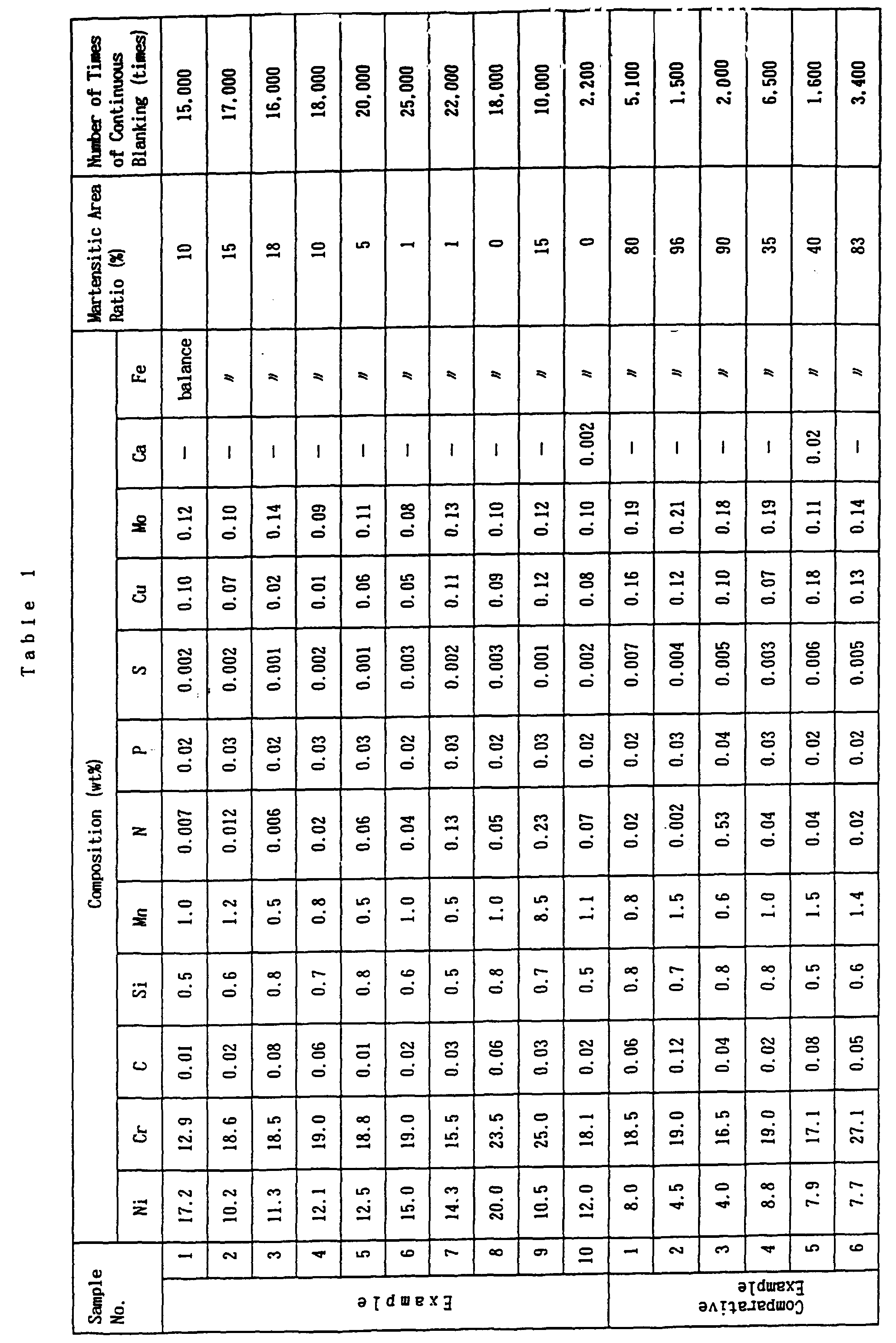
- As is evident from Table 1, the non-magnetic stainless steel having excellent workability used in the present invention exhibits a low martensitic area ratio and a number of times of continuous blanking which is increased about 2 to 10 times, as compared with the conventional non-magnetic materials shown in Comparative Examples 1 to 6. It is therefore possible to significantly decrease the number of times of re-grinding of the mold and significantly increase the production efficiency of precision parts.
- Further, since the toughness is improved by the Ni contained in the steel, and the deformation resistance during working is low because of the low carbon content, no fracture surface is formed by cracks, and a precision part having a smooth shearing surface and few burrs can be obtained at all times. There is thus no need for post-finishing of the fracture surface, and precision parts having high quality and high dimensional precision can be stably produced.
- In this embodiment, the occurrence of the adhesion of slugs, which is caused by ferromagnetization of the slugs, was hardly observed during working within the range of the numbers of times of blanking shown in Table 1. There is thus no need for the work of checking slugs, which is required for conventional steel materials, and the operation of the pressing system can be easily controlled.
- The grain size of each of the part materials prepared in Examples 1 to 10 was within the range of
grain size numbers 7 to 9. There is a tendency that, an increase in grain size number causes a decrease in grain size, hardening of the crystal, and the extension of the fracture surface produced during blanking. In order to obtain a precision part having a smooth shearing surface in this embodiment, it is therefore preferable to prepare a material so that the grain size number is within the range of 8.0 to 8.5. - This embodiment concerns the examples in which a precision part was formed by singly using the alloy material having each of the compositions shown in Table 1. However, it was confirmed that, when the non-magnetic stainless steel of the present invention was clad on one side or both sides of a specification plate material such as conventional 18-8 stainless steel, SUS304 or the like to form a composite material which was then subjected to blanking, the part produced exhibits the same excellent blanking quality. In this case, it was also confirmed that ratio of the thickness of the conventional stainless steel to the total thickness of the composite material is preferably 2 to 20%, more preferably 5 to 15%.
- As described above, the non-magnetic stainless steel having excellent workability used in the present invention shows a low deformation resistance during working and has no serious influence caused by slugs produced during blanking, as compared with conventional non-magnetic materials. Further, since the non-magnetic stainless steel of the present invention has a stable structure and is not magnetized, slugs do no adhere to the mold and the plate material. The non-magnetic stainless steel therefore permits a significant increase in the life of the mold used, the stable production of precision parts of high quality and a significant improvement in the efficiency of production of precision parts by strong working such as blanking or the like.
Claims (7)
- A precision part which is formed by blanking work and is made of non-magnetic stainless steel having excellent workability characterized by comprising an iron-based alloy containing 9 to 22 % by weight of nickel, 12 to 26 % by weight of chromium the balance of iron and inevitable impurities as well as optionally of 50 to 5000 ppm of nitrogen, optionally of 0.1 wt% or less of carbon and 1 wt% or less of silicon and optionally of 10 wt% or less of manganese wherein the martensitic area ratio of said iron-based alloy structure is 20 % or less.
- The precision part according to claim 1, wherein the content of copper contained as an impurity is set to 0.15 wt% or less.
- The precision part according to claim 1 or claim 2, wherein said alloy contains 10 to 20 % by weight of nickel and 15 to 20 % by weight of chromium.
- The precision part according to claim 3, wherein said alloy contains 11 to 16 % by weight of nickel and 16 to 19 % by weight of chromium.
- The precision part according to any of claims 1 to 4, wherein the precision part is a gear.
- A television set beam guide part formed by blanking and characterized by comprising the iron-based alloy as defined in any of claims 1 to 4.
- A method of producing a television set beam guide part characterized by comprising the steps of preparing a non-magnetic stainless steel plate by rolling an iron-based alloy containing 9 to 22 % by weight of nickel, 12 to 26 % by weight of chromium, balance of iron and inevitable impurities, and continuously blanking said non-magnetic stainless steel plate at a blanking temperature which is set so that a martensitic area ratio of said iron-based alloy after blanking is 20 % or less.
Applications Claiming Priority (2)
| Application Number | Priority Date | Filing Date | Title |
|---|---|---|---|
| JP148433/89 | 1989-06-13 | ||
| JP14843389 | 1989-06-13 |
Publications (3)
| Publication Number | Publication Date |
|---|---|
| EP0405226A2 EP0405226A2 (en) | 1991-01-02 |
| EP0405226A3 EP0405226A3 (en) | 1991-12-04 |
| EP0405226B1 true EP0405226B1 (en) | 1996-12-04 |
Family
ID=15452685
Family Applications (1)
| Application Number | Title | Priority Date | Filing Date |
|---|---|---|---|
| EP90111130A Expired - Lifetime EP0405226B1 (en) | 1989-06-13 | 1990-06-12 | Non-magnetic stainless steel |
Country Status (5)
| Country | Link |
|---|---|
| US (1) | US5098652A (en) |
| EP (1) | EP0405226B1 (en) |
| JP (1) | JP2753115B2 (en) |
| KR (1) | KR930007142B1 (en) |
| DE (1) | DE69029287T2 (en) |
Families Citing this family (15)
| Publication number | Priority date | Publication date | Assignee | Title |
|---|---|---|---|---|
| JP3017029B2 (en) * | 1994-09-28 | 2000-03-06 | 日鉱金属株式会社 | Nonmagnetic stainless steel for high burring forming and method for producing the same |
| JP2001164342A (en) * | 1999-09-28 | 2001-06-19 | Nippon Mining & Metals Co Ltd | Fe-Cr-Ni alloy for electron gun electrode and Fe-Cr-Ni alloy plate for electron gun electrode |
| MY121162A (en) * | 1999-09-28 | 2005-12-30 | Nippon Mining Co | Fe-cr-ni alloy for electron gun electrodes and fe-cr-ni alloy sheet for electron gun electrodes. |
| JP4199413B2 (en) * | 2000-10-31 | 2008-12-17 | 日鉱金属株式会社 | Fe-Cr-Ni alloy for electron gun electrode excellent in corrosion resistance and its strip |
| AT410550B (en) * | 2002-01-23 | 2003-05-26 | Boehler Edelstahl | Material used as a tool material in the glass industry, especially as a molding material for machine pressed glass consists of an alloy containing carbon, silicon, chromium, nickel and nitrogen |
| US6786624B2 (en) * | 2002-05-06 | 2004-09-07 | North American Lighting, Inc. | High temperature lighting bulb shield |
| US7218098B2 (en) * | 2003-09-12 | 2007-05-15 | Ford Global Technologies, Llc | Sensing an operating parameter of a target concealed from a sensor by an interposed component |
| JP4635954B2 (en) * | 2006-05-11 | 2011-02-23 | 住友金属工業株式会社 | Method for casting Cr-containing steel |
| JP4946758B2 (en) * | 2007-09-28 | 2012-06-06 | 住友金属工業株式会社 | High temperature austenitic stainless steel with excellent workability after long-term use |
| US20150010425A1 (en) | 2007-10-04 | 2015-01-08 | Nippon Steel & Sumitomo Metal Corporation | Austenitic stainless steel |
| US8486204B2 (en) * | 2010-11-17 | 2013-07-16 | Shin Zu Shing Co., Ltd. | Hinge device and electronic device using the same |
| JP5888737B2 (en) * | 2012-05-21 | 2016-03-22 | 日本冶金工業株式会社 | Austenitic Fe-Ni-Cr alloy |
| PL2975151T3 (en) * | 2013-03-14 | 2019-11-29 | Nippon Steel & Sumikin Sst | Ferritic stainless steel sheet exhibiting small increase in strength after thermal aging treatment, and method for producing same |
| RU2662512C2 (en) * | 2015-07-21 | 2018-07-26 | Федеральное государственное унитарное предприятие "Центральный научно-исследовательский институт конструкционных материалов "Прометей" имени И.В. Горынина Национального исследовательского центра "Курчатовский институт" (НИЦ "Курчатовский институт" - ЦНИИ КМ "Прометей") | Austenitic heat-resistant and corrosion-resistant steel |
| CN108531809B (en) * | 2018-05-14 | 2020-04-28 | 合肥东方节能科技股份有限公司 | Be used for hot rolling shaped steel guide crossbeam device |
Family Cites Families (8)
| Publication number | Priority date | Publication date | Assignee | Title |
|---|---|---|---|---|
| JPS505645A (en) * | 1973-05-22 | 1975-01-21 | ||
| SE7705578L (en) * | 1976-05-15 | 1977-11-16 | Nippon Steel Corp | TWO-PHASE STAINLESS STEEL |
| JPS5489916A (en) * | 1977-12-27 | 1979-07-17 | Sumitomo Electric Ind Ltd | Non-magnetic stainless steel |
| JPS55100966A (en) * | 1979-01-23 | 1980-08-01 | Kobe Steel Ltd | High strength austenite stainless steel having excellent corrosion resistance |
| US4288718A (en) * | 1979-05-24 | 1981-09-08 | Zenith Radio Corporation | Means and method for beam spot distortion compensation in TV picture tubes |
| US4371394A (en) * | 1980-11-21 | 1983-02-01 | Carpenter Technology Corporation | Corrosion resistant austenitic alloy |
| US4818484A (en) * | 1983-12-13 | 1989-04-04 | Carpenter Technology Corporation | Austenitic, non-magnetic, stainless steel alloy |
| DE3569061D1 (en) * | 1984-09-06 | 1989-04-27 | Toshiba Kk | Material for in-tube components & method of manufacture thereof |
-
1990
- 1990-06-11 US US07/536,311 patent/US5098652A/en not_active Expired - Lifetime
- 1990-06-12 DE DE69029287T patent/DE69029287T2/en not_active Expired - Lifetime
- 1990-06-12 EP EP90111130A patent/EP0405226B1/en not_active Expired - Lifetime
- 1990-06-12 JP JP2151683A patent/JP2753115B2/en not_active Expired - Lifetime
- 1990-06-13 KR KR1019900008669A patent/KR930007142B1/en not_active Expired - Lifetime
Also Published As
| Publication number | Publication date |
|---|---|
| KR930007142B1 (en) | 1993-07-30 |
| EP0405226A3 (en) | 1991-12-04 |
| EP0405226A2 (en) | 1991-01-02 |
| US5098652A (en) | 1992-03-24 |
| JP2753115B2 (en) | 1998-05-18 |
| KR920000960A (en) | 1992-01-29 |
| DE69029287D1 (en) | 1997-01-16 |
| DE69029287T2 (en) | 1997-04-03 |
| JPH03130348A (en) | 1991-06-04 |
Similar Documents
| Publication | Publication Date | Title |
|---|---|---|
| US5098652A (en) | Precision parts of non-magnetic stainless steels | |
| US20140241934A1 (en) | Steel sheet | |
| DE19803598C1 (en) | Soft magnetic iron-nickel alloy for relay armatures and yokes | |
| EP3358029A1 (en) | High-strength stainless steel sheet having excellent fatigue characteristics, and method for manufacturing same | |
| US20260078473A1 (en) | Austenitic alloy material | |
| EP1431410B1 (en) | Free cutting alloy | |
| JP4285303B2 (en) | Continuously variable transmission belt and stainless cold-rolled steel sheet therefor | |
| JP3426426B2 (en) | Fe-Ni alloy for electron gun parts and stamping parts for electron gun press | |
| JPH06316736A (en) | Ni-Fe based magnetic alloy excellent in magnetic properties and manufacturability and method for producing the same | |
| WO2025047240A1 (en) | Steel bar or wire rod | |
| US6459195B1 (en) | Fe-Cr-Ni alloy electron gun electroded and Fe-Cr-Ni alloy sheet for electron gun electrodes | |
| KR20250099456A (en) | Powder metallurgy tool steel | |
| JPH11106873A (en) | Alloy for electron gun electrode | |
| WO2022145064A1 (en) | Steel material | |
| KR100405395B1 (en) | Fe-Cr-Ni ALLOY FOR ELECTRON GUN ELECTRODES AND Fe-Cr-Ni ALLOY SHEET FOR ELECTRON GUN ELECTRODES | |
| JP3069482B2 (en) | Fe-Ni alloy cold rolled sheet with excellent plating and punching properties | |
| KR100210570B1 (en) | Fe-Ni Alloy and Electron Gun Press Punching Parts for Electron Gun Parts | |
| CN1077146C (en) | Fe-Ni alloys for electron gun parts and funched electron gun parts | |
| JP7560802B1 (en) | Steel | |
| CN1109120C (en) | Fe-Ni-Cr based alloy band steel having pressure shaping ability and used as electrode of electron gun | |
| KR100317687B1 (en) | PROCESS FOR PRODUCING Fe-Ni ALLOYS USED FOR ELECTRON GUN PARTS | |
| KR100294970B1 (en) | Fe-Ni Alloy and Electron Gun Press Punching Parts for Electron Gun Parts | |
| KR20030026966A (en) | Fe-ni or fe-ni-co or fe-ni-co-cu alloy strip with improved cuttability | |
| JPH09249943A (en) | Fe-Ni alloy for electron gun parts with good punchability and processed parts | |
| TW202519677A (en) | Cold rolled steel plate and manufacturing method thereof |
Legal Events
| Date | Code | Title | Description |
|---|---|---|---|
| PUAI | Public reference made under article 153(3) epc to a published international application that has entered the european phase |
Free format text: ORIGINAL CODE: 0009012 |
|
| 17P | Request for examination filed |
Effective date: 19900612 |
|
| AK | Designated contracting states |
Kind code of ref document: A2 Designated state(s): DE FR GB |
|
| PUAL | Search report despatched |
Free format text: ORIGINAL CODE: 0009013 |
|
| AK | Designated contracting states |
Kind code of ref document: A3 Designated state(s): DE FR GB |
|
| 17Q | First examination report despatched |
Effective date: 19930810 |
|
| GRAG | Despatch of communication of intention to grant |
Free format text: ORIGINAL CODE: EPIDOS AGRA |
|
| GRAH | Despatch of communication of intention to grant a patent |
Free format text: ORIGINAL CODE: EPIDOS IGRA |
|
| GRAH | Despatch of communication of intention to grant a patent |
Free format text: ORIGINAL CODE: EPIDOS IGRA |
|
| GRAA | (expected) grant |
Free format text: ORIGINAL CODE: 0009210 |
|
| AK | Designated contracting states |
Kind code of ref document: B1 Designated state(s): DE FR GB |
|
| REF | Corresponds to: |
Ref document number: 69029287 Country of ref document: DE Date of ref document: 19970116 |
|
| ET | Fr: translation filed | ||
| PLBE | No opposition filed within time limit |
Free format text: ORIGINAL CODE: 0009261 |
|
| STAA | Information on the status of an ep patent application or granted ep patent |
Free format text: STATUS: NO OPPOSITION FILED WITHIN TIME LIMIT |
|
| 26N | No opposition filed | ||
| REG | Reference to a national code |
Ref country code: GB Ref legal event code: 746 Effective date: 19981010 |
|
| REG | Reference to a national code |
Ref country code: FR Ref legal event code: D6 |
|
| REG | Reference to a national code |
Ref country code: GB Ref legal event code: IF02 |
|
| PGFP | Annual fee paid to national office [announced via postgrant information from national office to epo] |
Ref country code: GB Payment date: 20090610 Year of fee payment: 20 Ref country code: DE Payment date: 20090604 Year of fee payment: 20 |
|
| PGFP | Annual fee paid to national office [announced via postgrant information from national office to epo] |
Ref country code: FR Payment date: 20091117 Year of fee payment: 20 |
|
| REG | Reference to a national code |
Ref country code: GB Ref legal event code: PE20 Expiry date: 20100611 |
|
| PG25 | Lapsed in a contracting state [announced via postgrant information from national office to epo] |
Ref country code: GB Free format text: LAPSE BECAUSE OF EXPIRATION OF PROTECTION Effective date: 20100611 |
|
| PG25 | Lapsed in a contracting state [announced via postgrant information from national office to epo] |
Ref country code: DE Free format text: LAPSE BECAUSE OF EXPIRATION OF PROTECTION Effective date: 20100612 |