EP0404837B1 - Injection moulding of a preform and/or a container and a container of thermoplastic material - Google Patents
Injection moulding of a preform and/or a container and a container of thermoplastic material Download PDFInfo
- Publication number
- EP0404837B1 EP0404837B1 EP89904629A EP89904629A EP0404837B1 EP 0404837 B1 EP0404837 B1 EP 0404837B1 EP 89904629 A EP89904629 A EP 89904629A EP 89904629 A EP89904629 A EP 89904629A EP 0404837 B1 EP0404837 B1 EP 0404837B1
- Authority
- EP
- European Patent Office
- Prior art keywords
- container
- plastics material
- bottom portion
- preform
- plastics
- Prior art date
- Legal status (The legal status is an assumption and is not a legal conclusion. Google has not performed a legal analysis and makes no representation as to the accuracy of the status listed.)
- Expired - Lifetime
Links
- 238000001746 injection moulding Methods 0.000 title claims abstract description 13
- 239000012815 thermoplastic material Substances 0.000 title claims description 10
- 239000000463 material Substances 0.000 claims abstract description 93
- 239000004033 plastic Substances 0.000 claims abstract description 42
- 229920003023 plastic Polymers 0.000 claims abstract description 42
- 238000000034 method Methods 0.000 claims abstract description 10
- 238000002347 injection Methods 0.000 claims description 13
- 239000007924 injection Substances 0.000 claims description 13
- 229920000139 polyethylene terephthalate Polymers 0.000 claims description 10
- 239000005020 polyethylene terephthalate Substances 0.000 claims description 9
- 229920000728 polyester Polymers 0.000 claims description 6
- 239000004952 Polyamide Substances 0.000 claims description 5
- 229920002647 polyamide Polymers 0.000 claims description 5
- 229920002239 polyacrylonitrile Polymers 0.000 claims description 4
- 229920000515 polycarbonate Polymers 0.000 claims description 4
- 239000004417 polycarbonate Substances 0.000 claims description 4
- -1 polyethylene terephthalate Polymers 0.000 claims description 4
- 239000000203 mixture Substances 0.000 claims description 3
- OKTJSMMVPCPJKN-UHFFFAOYSA-N Carbon Chemical compound [C] OKTJSMMVPCPJKN-UHFFFAOYSA-N 0.000 claims 1
- 229910052799 carbon Inorganic materials 0.000 claims 1
- 239000011521 glass Substances 0.000 claims 1
- 239000002245 particle Substances 0.000 claims 1
- 230000003014 reinforcing effect Effects 0.000 claims 1
- 238000004519 manufacturing process Methods 0.000 description 6
- 238000002425 crystallisation Methods 0.000 description 5
- 238000004891 communication Methods 0.000 description 4
- 230000002787 reinforcement Effects 0.000 description 4
- 230000006641 stabilisation Effects 0.000 description 4
- 238000011105 stabilization Methods 0.000 description 4
- 238000007664 blowing Methods 0.000 description 2
- 230000008025 crystallization Effects 0.000 description 2
- 230000009477 glass transition Effects 0.000 description 2
- 238000010438 heat treatment Methods 0.000 description 2
- 235000010627 Phaseolus vulgaris Nutrition 0.000 description 1
- 244000046052 Phaseolus vulgaris Species 0.000 description 1
- 238000000071 blow moulding Methods 0.000 description 1
- 238000001816 cooling Methods 0.000 description 1
- 230000001419 dependent effect Effects 0.000 description 1
- 230000000694 effects Effects 0.000 description 1
- 238000003780 insertion Methods 0.000 description 1
- 230000037431 insertion Effects 0.000 description 1
- 238000007493 shaping process Methods 0.000 description 1
- 238000003892 spreading Methods 0.000 description 1
- 238000003860 storage Methods 0.000 description 1
Images

Classifications
-
- B—PERFORMING OPERATIONS; TRANSPORTING
- B65—CONVEYING; PACKING; STORING; HANDLING THIN OR FILAMENTARY MATERIAL
- B65D—CONTAINERS FOR STORAGE OR TRANSPORT OF ARTICLES OR MATERIALS, e.g. BAGS, BARRELS, BOTTLES, BOXES, CANS, CARTONS, CRATES, DRUMS, JARS, TANKS, HOPPERS, FORWARDING CONTAINERS; ACCESSORIES, CLOSURES, OR FITTINGS THEREFOR; PACKAGING ELEMENTS; PACKAGES
- B65D1/00—Rigid or semi-rigid containers having bodies formed in one piece, e.g. by casting metallic material, by moulding plastics, by blowing vitreous material, by throwing ceramic material, by moulding pulped fibrous material or by deep-drawing operations performed on sheet material
- B65D1/40—Details of walls
-
- B—PERFORMING OPERATIONS; TRANSPORTING
- B29—WORKING OF PLASTICS; WORKING OF SUBSTANCES IN A PLASTIC STATE IN GENERAL
- B29C—SHAPING OR JOINING OF PLASTICS; SHAPING OF MATERIAL IN A PLASTIC STATE, NOT OTHERWISE PROVIDED FOR; AFTER-TREATMENT OF THE SHAPED PRODUCTS, e.g. REPAIRING
- B29C45/00—Injection moulding, i.e. forcing the required volume of moulding material through a nozzle into a closed mould; Apparatus therefor
- B29C45/16—Making multilayered or multicoloured articles
- B29C45/1642—Making multilayered or multicoloured articles having a "sandwich" structure
Definitions
- the present invention in general relates to the provision of a bottom reinforcement of plastics material in a container of thermoplastic material and in particular relates to a method of producing a preform and/or a container according to the preamble of claim 1 and to a container of thermoplastic material according to the preamble of claim 6.
- Relevant background art is disclosed in the document DE-A-2 308 571.
- Containers of thermoplastic material have bean employed to a steadily increasing degree for the storage of goods in which the containers have, either in conjunction with supply of the goods, or once the goods have been placed in the container, been exposed to temperatures exceeding the glass transition temperature of the thermoplastic material.
- One example hereof is containers of polyethyleneterephthalate (PET).
- thermoplastic material properties which entail that the container will retain its shape even when heated to relatively high temperatures.
- temperature stabilization is effected in that, on their production, the containers are formed by blowing a blank against hot mould walls (blow moulding), and that the excess pressure created for the blowing is maintained within the moulded container for a predetermined period of time. On abutment of the material against the hot mould walls, the material in the container is heated to a relatively high temperature, at the same time as the container is forced to retain its form in that the excess pressure is maintained in the interior of the container.
- thermocrystallization In order to attain fully satisfactory form stability, it is required that, in case of for example PET, the thermally-conditioned crystallization is allowed to continue until such time as the material becomes opaque, which requires considerably longer heating times, as a rule at least of the order of magnitude of 60 s.
- Lengthy dwell times in the tools entail high production costs, which is of considerable economic disadvantage in the production of containers of the type under consideration here, since such containers are produced in very large numbers.
- the present invention obviates the above-outlined drawbacks. Its effects will be attained by a method according to the characterizing clause of claim 1, and by a container having the features disclosed in the characterizing clause of claim 6.
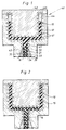
- Figs. 1 and 2 show an injection moulding machine 30 provided with an inner nozzle 31 and an outer nozzle 32.
- the injection moulding machine is connected to an injection mould 40 composed of an outer mould portion 41 and an inner mould portion 42.
- the injection mould 40 is provided with a receptacle portion 43 to which a connecting portion 33 of the injection moulding machine 30 is connected.
- a connecting portion 33 there are disposed a first supply channel 34 and a second supply channel 35 which, once the connecting portion 33 and the receptacle portion 43 have been interconnected, merge in a communication channel 45 which is located in the injection mould 40.
- the communication channel connects to a mould cavity 44 in the injection mould.
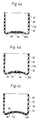
- Figs. 3a, 3b and 3c illustrate a body 10a, 10b, 10c which, in certain embodiments, constitutes a preform from which a container 11a, 11b, 11c is formed (Figs. 4a,4b). In certain embodiments, the body constitutes the finished container.
- the container comprises a container body 12, a mouth portion 13 and a bottom portion 20a, 20b, 20c.
- the container is shown in embodiments in which the container is composed of a first plastics material 15 and a second plastics material 16.
- the second plastics material is in direct contact with the surroundings in a central region 17 of the outer surface of the bottom portion.
- the second plastics material 16 is whollys enclosed by the first plastics material 15 of the container and the preform, respectively.
- the first plastics material 15 is wholly enclosed by the seconds plastic material 16 of the container and the preform, respectively.
- the second plastics material consists of a plastics material which is of a higher rigidity than the first material at a temperature which is higher than the softening point of the first material.
- softening point is here taken to mean primarily the glass transition temperature of the material.
- Rapidly crystallizing material is particularly well suited for use in the embodiments according to Figs. 3c and 4c, in which the reinforcement plates form a bounding definition of the bottom portion facing towards the "interior" of the container and/or towards the "exterior” of the container.
- the second plastics material forms, in a region which is as a rule enclosed or surrounded by the standing surface of the container, a plate-like reinforcement layer.
- this reinforcement layer is centered about the axis of the container and, as a rule, forms a substantially circular plate or disc.
- the second plastics material consists of a thermoplastic material, preferably of polyamide, polycarbonate, polyester, in particular polyethylene terephthalate, and polyacrylonitrile or mixtures thereof.
- a rapidly crystallizing quality of such material is selected.
- the first plastics material consists of a thermoplastic material, preferably of a polyester, such as PET, or a polyamide.
- the plate shown in the figures is determinative of the capability of the container to withstand elevated temperatures in its bottom portion.
- requisite temperature stability in the container body of the container is attained in that the material therein undergoes orientation and, as a rule, biaxial orientation.
- subsequent temperature stabilization which is effected by heating the material to a temperature adapted to the highest temperature at which the material is intended to be used, there will be attained the contemplated stability in the container body. Since the material in the container body is relatively thin, said temperature stabilization of the material is relatively simple to achieve. On the other hand, for the bottom of the container, the material is oriented to but a slight extent, and moreover the material is often relatively thick.
- thermo-crystallization of the material takes a relatively lengthy time, which in the mass production of articles, for example the production of containers, entails unacceptably high costs.
- the plate of the second plastics material By the insertion of the plate of the second plastics material in the bottom portion, the mechanical stability and rigidity of the bottom portion will also be obtained at elevated temperatures. Since the plate of the second plastics material will only consist of a relatively slight amount of material, employment of the above plate will not entail any unacceptable increase in the cost of the finished product. Selection of material for the plate will also determine the maximum temperature at which the bottom portion remains mechanically stable. As a rule, no after-treatment in the form of thermo-crystallization is, therefore, required.
- the shaping of a preform or the forming of a container commences in that the first material 15 is fed via the outer nozzle 32 of the injection moulding machine, into the mould cavity 44 of the injection mould 40.
- the material is cooled more rapidly against the walls of the injection mould than in a central layer, which implies that, when the second plastics material 16 is fed via the inner nozzle 31, into the communication channel 45 of the receptacle portion of the injection mould, the second material will displace the first material in a central layer out towards the as yet unfilled parts of the mould cavity (cf. Fig. 2).
- a layer of a second material will be formed centrally in the first material.
- the two mould portions 41 and 42 are separated the thus formed body (the preform), or alternatively the container, being exposed and may be removed from the injection mould. Residual material in connection with the communication channel 45 is removed from the formed body.
- a mechanical post-forming of the bottom portion may be carried out in order that this will obtain the forms illustrated in Figs. 4a and 4b, respectively.
- the mould cavity of the injection mould is selected and dimensioned in such a manner that the bottom portion obtains, already in conjunction with the injection moulding, a final form similar to that illustrated in Figs. 4a and 4b, respectively.
Landscapes
- Engineering & Computer Science (AREA)
- Mechanical Engineering (AREA)
- Manufacturing & Machinery (AREA)
- Ceramic Engineering (AREA)
- Processing And Handling Of Plastics And Other Materials For Molding In General (AREA)
- Injection Moulding Of Plastics Or The Like (AREA)
- Blow-Moulding Or Thermoforming Of Plastics Or The Like (AREA)
- Containers Having Bodies Formed In One Piece (AREA)
- Table Devices Or Equipment (AREA)
- Finishing Walls (AREA)
- Moulds For Moulding Plastics Or The Like (AREA)
- Details Of Rigid Or Semi-Rigid Containers (AREA)
- Laminated Bodies (AREA)
- Auxiliary Devices For And Details Of Packaging Control (AREA)
- Cartons (AREA)
Abstract
Description
- The present invention in general relates to the provision of a bottom reinforcement of plastics material in a container of thermoplastic material and in particular relates to a method of producing a preform and/or a container according to the preamble of claim 1 and to a container of thermoplastic material according to the preamble of claim 6. Relevant background art is disclosed in the document DE-A-2 308 571.
- Containers of thermoplastic material have bean employed to a steadily increasing degree for the storage of goods in which the containers have, either in conjunction with supply of the goods, or once the goods have been placed in the container, been exposed to temperatures exceeding the glass transition temperature of the thermoplastic material. One example hereof is containers of polyethyleneterephthalate (PET).
- It is previously known, for example from US-A-4 264 558, to impart to the container, by so-called temperature stabilization of the thermoplastic material, properties which entail that the container will retain its shape even when heated to relatively high temperatures. Such temperature stabilization is effected in that, on their production, the containers are formed by blowing a blank against hot mould walls (blow moulding), and that the excess pressure created for the blowing is maintained within the moulded container for a predetermined period of time. On abutment of the material against the hot mould walls, the material in the container is heated to a relatively high temperature, at the same time as the container is forced to retain its form in that the excess pressure is maintained in the interior of the container. Hereby, those stresses which have been embodied in the material on its orientation are released, at the same time as its thermally-conditioned crystallization increases. In addition, amorphous material included in the container, in the bottom portion and/or in the mouth portion undergoes thermocrystallization. In order to attain fully satisfactory form stability, it is required that, in case of for example PET, the thermally-conditioned crystallization is allowed to continue until such time as the material becomes opaque, which requires considerably longer heating times, as a rule at least of the order of magnitude of 60 s.
- Lengthy dwell times in the tools entail high production costs, which is of considerable economic disadvantage in the production of containers of the type under consideration here, since such containers are produced in very large numbers.
- The present invention obviates the above-outlined drawbacks. Its effects will be attained by a method according to the characterizing clause of claim 1, and by a container having the features disclosed in the characterizing clause of claim 6.
- According to the present invention, the bottom portion is formed of a plastics material which remains mechanically stable, i.e. retains its rigidity, at a temperature which is higher than the temperature at which the surrounding material begins to soften. Otherwise expressed, there exists a rigidity gradient between the materials. In one preferred embodiment, the relatively more rigid material is given a plate-like shape and is often designed as a substantially circular disc in the region of the axis of the hollow body.
- Examples of plastics materials which may be used according to the present invention in order to increase the capability of the bottom portion to retain mechanical stability and rigidity at elevated temperatures are polyamide, polyester, in particular polyethyleneterephthalate, polycarbonate and polyacrylonitrile.
- It should be observed that, having once gained an insight into the present invention and its aspects, the skilled reader of this specification will be in a position to select, without difficulty, those materials and combinations thereof which are suitable in each physical application. Materials described herein are to be taken solely as examples and the present invention is by no means restricted thereto.
- Further appropriate embodiments of the present invention are set forth in the dependent claims.
- The nature of the present invention and its aspects will be more readily understood from the following brief description of the accompanying drawings, and discussion relating thereto.
- In the accompanying drawings:
- Fig. 1
- is a section through an injection nozzle and a mould connected to the injection nozzle during commenced injection moulding of a body from which the container according to the present invention is thereafter formed;
- Fig 2
- is a section corresponding to that of Fig. 1 once the injection moulding of the body has been completed;
- Figs. 3a,3b,3c
- are sections through embodiments of bodies formed by means of an apparatus according to Figs. 1 and 2; and
- Figs. 4a,4b,4c
- show containers formed from the bodies according to Figs.3a-3c.
- Referring to the drawings, Figs. 1 and 2 show an injection moulding machine 30 provided with an
inner nozzle 31 and anouter nozzle 32. - The injection moulding machine is connected to an
injection mould 40 composed of anouter mould portion 41 and aninner mould portion 42. Theinjection mould 40 is provided with areceptacle portion 43 to which a connectingportion 33 of the injection moulding machine 30 is connected. In the connectingportion 33, there are disposed a first supply channel 34 and asecond supply channel 35 which, once the connectingportion 33 and thereceptacle portion 43 have been interconnected, merge in acommunication channel 45 which is located in theinjection mould 40. The communication channel connects to amould cavity 44 in the injection mould. - Figs. 3a, 3b and 3c illustrate a
body container - The container comprises a
container body 12, amouth portion 13 and abottom portion first plastics material 15 and asecond plastics material 16. In the embodiments in Figs. 3b and 4b, respectively, the second plastics material is in direct contact with the surroundings in acentral region 17 of the outer surface of the bottom portion. In the embodiment illustrated in Figs. 3a and 4a, respectively, thesecond plastics material 16 is whollys enclosed by thefirst plastics material 15 of the container and the preform, respectively. In the embodiment illustrated in Figs. 3c and 4c, respectively, thefirst plastics material 15 is wholly enclosed by the secondsplastic material 16 of the container and the preform, respectively. The second plastics material consists of a plastics material which is of a higher rigidity than the first material at a temperature which is higher than the softening point of the first material. The term softening point is here taken to mean primarily the glass transition temperature of the material. Rapidly crystallizing material is particularly well suited for use in the embodiments according to Figs. 3c and 4c, in which the reinforcement plates form a bounding definition of the bottom portion facing towards the "interior" of the container and/or towards the "exterior" of the container. As a result of the arrangement illustrated in the figure, material is directly accessible for abutment against hot forming devices for transferring thermo energy to the material and thermo-crystallization thereof occasioned thereby. In the illustrated embodiments, the second plastics material forms, in a region which is as a rule enclosed or surrounded by the standing surface of the container, a plate-like reinforcement layer. Generally, this reinforcement layer is centered about the axis of the container and, as a rule, forms a substantially circular plate or disc. - As was mentioned above, the second plastics material consists of a thermoplastic material, preferably of polyamide, polycarbonate, polyester, in particular polyethylene terephthalate, and polyacrylonitrile or mixtures thereof. In those embodiments wherein the second plastics material consists of polyethylene terephthalate, a rapidly crystallizing quality of such material is selected.
- The first plastics material consists of a thermoplastic material, preferably of a polyester, such as PET, or a polyamide.
- The plate shown in the figures is determinative of the capability of the container to withstand elevated temperatures in its bottom portion. As a rule, requisite temperature stability in the container body of the container is attained in that the material therein undergoes orientation and, as a rule, biaxial orientation. As a result of subsequent temperature stabilization, which is effected by heating the material to a temperature adapted to the highest temperature at which the material is intended to be used, there will be attained the contemplated stability in the container body. Since the material in the container body is relatively thin, said temperature stabilization of the material is relatively simple to achieve. On the other hand, for the bottom of the container, the material is oriented to but a slight extent, and moreover the material is often relatively thick. Since plastics material suffers from poor thermal conductivity, a thermo-crystallization of the material takes a relatively lengthy time, which in the mass production of articles, for example the production of containers, entails unacceptably high costs. By the insertion of the plate of the second plastics material in the bottom portion, the mechanical stability and rigidity of the bottom portion will also be obtained at elevated temperatures. Since the plate of the second plastics material will only consist of a relatively slight amount of material, employment of the above plate will not entail any unacceptable increase in the cost of the finished product. Selection of material for the plate will also determine the maximum temperature at which the bottom portion remains mechanically stable. As a rule, no after-treatment in the form of thermo-crystallization is, therefore, required.
- In the production of a container according to the present invention, the shaping of a preform or the forming of a container commences in that the
first material 15 is fed via theouter nozzle 32 of the injection moulding machine, into themould cavity 44 of theinjection mould 40. The material is cooled more rapidly against the walls of the injection mould than in a central layer, which implies that, when thesecond plastics material 16 is fed via theinner nozzle 31, into thecommunication channel 45 of the receptacle portion of the injection mould, the second material will displace the first material in a central layer out towards the as yet unfilled parts of the mould cavity (cf. Fig. 2). In such instance, a layer of a second material will be formed centrally in the first material. - By selection of the fill factor of the mould cavity before the introduction of material through the
inner nozzle 31 is commenced, and selection of the moment herefor, the size and thickness, respectively, will be determined for that plate which thesecond material 16 forms, in the preform and in the finished container, respectively. By the passage of heat-controlling medium - through the channels 46-47 of the outer andinner mould portions mould portions communication channel 45 is removed from the formed body. - In certain embodiments, for example a mechanical post-forming of the bottom portion may be carried out in order that this will obtain the forms illustrated in Figs. 4a and 4b, respectively. In other embodiments, the mould cavity of the injection mould is selected and dimensioned in such a manner that the bottom portion obtains, already in conjunction with the injection moulding, a final form similar to that illustrated in Figs. 4a and 4b, respectively.
- It should be pointed out that the relationships illustrated in the figures between the outer dimensions of the formed bodies, for example diameter, height and material thickness of the container body and bottom portion, respectively, have been exaggerated in order more clearly to illustrate the inventive concept as herein disclosed.
- The above detailed description has referred to but a limited number of embodiments of the present invention, but skilled in the art will readily perceive that the present invention encompasses a large number of embodiments without departing from the scope of the appended claims.
Claims (11)
- A method of producing a container or a preform for reshaping to a container, having a closed bottom portion with increased temperature stability, said container including a multi-layer structure comprising a first plastics material and a second plastics material, in which an injection moulding machine, operative for at least double layer injection, injection moulds the container or the preform, characterised in that the injection moulding machine, on forming of the container or the preform, is controlled in such a way that the second plastics material is disposed only in said bottom portion, and that there is a rigidity gradient between said two materials such that the second plastics material has a higher rigidity than the first plastics material at a temperature which is higher than the softening point of the first material.
- The method as claimed in claim 1, wherein the second plastics material is disposed in a region which, in the finished container, encompasses a region inside the standing surface of the container.
- The method as claimed un claim 1 or 2, wherein the second plastics material layer is disposed as a substantially circular plate or disc in the region of the axis of the container.
- The method as claimed in any one of the preceding claims, wherein the second plastics material consists of a thermoplastic material comprising polyamide, polycarbonate, polyester, polyacrylonitrile, or mixtures thereof.
- The method as claimed in claim 4, wherein the polyester comprises polyethylene terephthalate, in particular rapidly-crystallising polyethylene terephtalate.
- A container of substantially thermoplastic material having a closed bottom portion (20a, 20b, 20c) with elevated temperature stability, the bottom portion comprising a multi-layer material composed of at least a first plastics material (15) and a second plastics material (16), characterised in that in at least the central portion (21, 21a) of the bottom portion (20, 20a) there is included one or more plates (22) and/or discs (22a) of the second material (16), and that there is a rigidity gradient between said two materials (15, 16) such that the second material (16) has a higher rigidity than the first material (15) at a temperature which is higher than the softening point of the first material (15).
- The container as claimed in claim 6, wherein said plates (22) and/or discs (22a) are rendered discrete from contact with the interior of the container by the first plastics material (15).
- The container as claimed in claim 6, wherein said plates (22) and/or discs (22a) on both sides enclose the first plastics material (15), i.e. towards both the interior and the exterior of the container (11a, 11b, 11c).
- The container as claimed in claim 6, wherein the first plastics material (15), at least on one side but preferably on both sides, encloses the second plastics material (16).
- The container as claimed in any one of claims 6-9, wherein said plates (22) and/or discs (22a) consist of polyamide, polycarbonate, polyester, in particular polyethylene terephthalate, polyacrylonitrile, or mixtures thereof.
- The container as claimed in any one of claims 6-10, wherein the second plastics material (16) is reinforced in that mechanically reinforcing bodies of fibres, balls, particles etc of, for example glass, carbon etc, are incorporated into the material.
Applications Claiming Priority (3)
| Application Number | Priority Date | Filing Date | Title |
|---|---|---|---|
| SE8801284A SE468886B (en) | 1988-04-08 | 1988-04-08 | PROVIDED TO MAKE A CONTAINER OR PROCEDURE INTENDED TO BE TRANSFORMED TO A CONTAINER AND AN ARTICLE CONCERNING A CONTAINER OR A PROCEDURE FOR A CONTAINER MADE AS SET |
| SE8801284 | 1988-04-08 | ||
| PCT/SE1989/000179 WO1989009688A1 (en) | 1988-04-08 | 1989-04-06 | Injection moulding of a preform and/or a container and a container of thermoplastic material |
Publications (2)
| Publication Number | Publication Date |
|---|---|
| EP0404837A1 EP0404837A1 (en) | 1991-01-02 |
| EP0404837B1 true EP0404837B1 (en) | 1994-12-28 |
Family
ID=20371936
Family Applications (1)
| Application Number | Title | Priority Date | Filing Date |
|---|---|---|---|
| EP89904629A Expired - Lifetime EP0404837B1 (en) | 1988-04-08 | 1989-04-06 | Injection moulding of a preform and/or a container and a container of thermoplastic material |
Country Status (9)
| Country | Link |
|---|---|
| EP (1) | EP0404837B1 (en) |
| JP (1) | JPH03502669A (en) |
| AT (1) | ATE116189T1 (en) |
| AU (1) | AU626152B2 (en) |
| DE (1) | DE68920312T2 (en) |
| FI (1) | FI91504C (en) |
| NO (1) | NO178224C (en) |
| SE (1) | SE468886B (en) |
| WO (1) | WO1989009688A1 (en) |
Families Citing this family (1)
| Publication number | Priority date | Publication date | Assignee | Title |
|---|---|---|---|---|
| DE19907508A1 (en) * | 1999-02-22 | 2000-08-24 | Hench Gmbh H | Tubular injection molded plastic component with integral connectors for cleaning equipment is molded in a single stage with a thin outer plastic cover and reinforced inner layer |
Family Cites Families (7)
| Publication number | Priority date | Publication date | Assignee | Title |
|---|---|---|---|---|
| GB1362133A (en) * | 1972-02-24 | 1974-07-30 | Ici Ltd | Injection blow moulding |
| SE389653B (en) * | 1974-03-25 | 1976-11-15 | Haustrups Fabriker As | PLASTIC CONTAINER WITH REINFORCED BOTTOM AND SIDE WALL |
| US4609516A (en) * | 1984-02-17 | 1986-09-02 | Continental Pet Technologies, Inc. | Method of forming laminated preforms |
| JPS60240409A (en) * | 1984-05-15 | 1985-11-29 | Mitsubishi Gas Chem Co Inc | Preparation of multilayer parison |
| US4657496A (en) * | 1984-06-04 | 1987-04-14 | Gifu Husky Co., Ltd. | Hot-runner mold for injection molding |
| JPS6137404A (en) * | 1984-07-31 | 1986-02-22 | Nissei Ee S B Kikai Kk | Method of injection molding multilayered parison with bottom |
| JPS63194912A (en) * | 1987-02-09 | 1988-08-12 | Nissei Ee S B Kikai Kk | Preform for biaxially orienting container and molding method thereof |
-
1988
- 1988-04-08 SE SE8801284A patent/SE468886B/en not_active IP Right Cessation
-
1989
- 1989-04-06 AT AT89904629T patent/ATE116189T1/en not_active IP Right Cessation
- 1989-04-06 WO PCT/SE1989/000179 patent/WO1989009688A1/en not_active Ceased
- 1989-04-06 DE DE68920312T patent/DE68920312T2/en not_active Expired - Fee Related
- 1989-04-06 JP JP1504232A patent/JPH03502669A/en active Pending
- 1989-04-06 EP EP89904629A patent/EP0404837B1/en not_active Expired - Lifetime
- 1989-04-06 AU AU34230/89A patent/AU626152B2/en not_active Ceased
- 1989-12-04 FI FI895801A patent/FI91504C/en not_active IP Right Cessation
- 1989-12-05 NO NO894853A patent/NO178224C/en unknown
Also Published As
| Publication number | Publication date |
|---|---|
| FI91504B (en) | 1994-03-31 |
| NO894853D0 (en) | 1989-12-05 |
| NO178224B (en) | 1995-11-06 |
| AU626152B2 (en) | 1992-07-23 |
| NO178224C (en) | 1996-02-14 |
| NO894853L (en) | 1989-12-05 |
| DE68920312D1 (en) | 1995-02-09 |
| JPH03502669A (en) | 1991-06-20 |
| WO1989009688A1 (en) | 1989-10-19 |
| FI895801A0 (en) | 1989-12-04 |
| SE468886B (en) | 1993-04-05 |
| EP0404837A1 (en) | 1991-01-02 |
| DE68920312T2 (en) | 1995-05-18 |
| SE8801284L (en) | 1989-10-09 |
| SE8801284D0 (en) | 1988-04-08 |
| ATE116189T1 (en) | 1995-01-15 |
| FI91504C (en) | 1994-07-11 |
| AU3423089A (en) | 1989-11-03 |
Similar Documents
| Publication | Publication Date | Title |
|---|---|---|
| US5122327A (en) | Blow molding method for making a reversely oriented hot fill container | |
| CN100441391C (en) | Method and apparatus for localized crystallization of amorphous plastic articles | |
| CA1065111A (en) | Method and apparatus for the preparation of hollow plastic articles | |
| RU2060889C1 (en) | Method of injection orientation blow moulding | |
| US8691140B2 (en) | Process for injection molding of thin-walled preform | |
| JPS625781B2 (en) | ||
| JPS55142623A (en) | Method of forming optical pattern in polyethylene terephthalate resin made product and method of reinforcing optical pattern formed by the said method | |
| WO1997032706A1 (en) | Compression molding process | |
| EP0725722B1 (en) | Method of forming molecularly oriented preforms | |
| JP3281073B2 (en) | Injection stretch blow molding machine | |
| EP0654340B1 (en) | Method for injection stretch blow molding of polyethylene | |
| CN1104315C (en) | Method for producing filled rigid containers of plastic | |
| JPH1134152A (en) | Large-sized container and its molding method | |
| EP2780146A1 (en) | Plural blow utilization of counter stretch rod and/or base pushup | |
| EP0404837A1 (en) | Injection moulding of a preform and/or a container and a container of thermoplastic material. | |
| DE69404474T2 (en) | METHOD FOR SHAPING MOLECULAR-ORIENTED PREFORMS | |
| EP0765725B1 (en) | Process for injection molding polyethylene terephthalate | |
| GB2055672A (en) | Method of blow moulding bottle of saturated polyester | |
| RU2194655C1 (en) | Method of manufacture of filled-in rigid plastic container | |
| JP2963644B2 (en) | Molding method of plastic bottle having constricted shape | |
| JP3135173B2 (en) | Forming method of crystallized neckpiece | |
| WO2026100664A1 (en) | Method and device for producing resin container | |
| DK171465B1 (en) | Method for the manufacture of a container or a preform therefor and container manufactured by the method | |
| CA1144723A (en) | Method of fabricating bottle-shaped container of saturated polyester | |
| JPH0655417B2 (en) | Method for producing polyethylene terephthalate container having excellent heat resistance |
Legal Events
| Date | Code | Title | Description |
|---|---|---|---|
| PUAI | Public reference made under article 153(3) epc to a published international application that has entered the european phase |
Free format text: ORIGINAL CODE: 0009012 |
|
| 17P | Request for examination filed |
Effective date: 19900402 |
|
| AK | Designated contracting states |
Kind code of ref document: A1 Designated state(s): AT BE CH DE FR GB IT LI NL SE |
|
| R17P | Request for examination filed (corrected) |
Effective date: 19900402 |
|
| 17Q | First examination report despatched |
Effective date: 19921229 |
|
| RAP1 | Party data changed (applicant data changed or rights of an application transferred) |
Owner name: PLM AB |
|
| GRAA | (expected) grant |
Free format text: ORIGINAL CODE: 0009210 |
|
| REF | Corresponds to: |
Ref document number: 116189 Country of ref document: AT Date of ref document: 19950115 Kind code of ref document: T |
|
| ITF | It: translation for a ep patent filed | ||
| REF | Corresponds to: |
Ref document number: 68920312 Country of ref document: DE Date of ref document: 19950209 |
|
| ET | Fr: translation filed | ||
| PLBE | No opposition filed within time limit |
Free format text: ORIGINAL CODE: 0009261 |
|
| STAA | Information on the status of an ep patent application or granted ep patent |
Free format text: STATUS: NO OPPOSITION FILED WITHIN TIME LIMIT |
|
| 26N | No opposition filed | ||
| REG | Reference to a national code |
Ref country code: GB Ref legal event code: IF02 |
|
| PGFP | Annual fee paid to national office [announced via postgrant information from national office to epo] |
Ref country code: GB Payment date: 20020320 Year of fee payment: 14 |
|
| PGFP | Annual fee paid to national office [announced via postgrant information from national office to epo] |
Ref country code: BE Payment date: 20020409 Year of fee payment: 14 |
|
| PGFP | Annual fee paid to national office [announced via postgrant information from national office to epo] |
Ref country code: FR Payment date: 20020410 Year of fee payment: 14 |
|
| PG25 | Lapsed in a contracting state [announced via postgrant information from national office to epo] |
Ref country code: GB Free format text: LAPSE BECAUSE OF NON-PAYMENT OF DUE FEES Effective date: 20030406 |
|
| PG25 | Lapsed in a contracting state [announced via postgrant information from national office to epo] |
Ref country code: BE Free format text: LAPSE BECAUSE OF NON-PAYMENT OF DUE FEES Effective date: 20030430 |
|
| BERE | Be: lapsed |
Owner name: *PLM A.B. Effective date: 20030430 |
|
| GBPC | Gb: european patent ceased through non-payment of renewal fee |
Effective date: 20030406 |
|
| PG25 | Lapsed in a contracting state [announced via postgrant information from national office to epo] |
Ref country code: FR Free format text: LAPSE BECAUSE OF NON-PAYMENT OF DUE FEES Effective date: 20031231 |
|
| REG | Reference to a national code |
Ref country code: FR Ref legal event code: ST |
|
| PGFP | Annual fee paid to national office [announced via postgrant information from national office to epo] |
Ref country code: SE Payment date: 20050404 Year of fee payment: 17 |
|
| PGFP | Annual fee paid to national office [announced via postgrant information from national office to epo] |
Ref country code: NL Payment date: 20050405 Year of fee payment: 17 Ref country code: DE Payment date: 20050405 Year of fee payment: 17 Ref country code: CH Payment date: 20050405 Year of fee payment: 17 |
|
| PG25 | Lapsed in a contracting state [announced via postgrant information from national office to epo] |
Ref country code: IT Free format text: LAPSE BECAUSE OF NON-PAYMENT OF DUE FEES Effective date: 20050406 |
|
| PGFP | Annual fee paid to national office [announced via postgrant information from national office to epo] |
Ref country code: AT Payment date: 20050406 Year of fee payment: 17 |
|
| PG25 | Lapsed in a contracting state [announced via postgrant information from national office to epo] |
Ref country code: AT Free format text: LAPSE BECAUSE OF NON-PAYMENT OF DUE FEES Effective date: 20060406 |
|
| PG25 | Lapsed in a contracting state [announced via postgrant information from national office to epo] |
Ref country code: SE Free format text: LAPSE BECAUSE OF NON-PAYMENT OF DUE FEES Effective date: 20060407 |
|
| PG25 | Lapsed in a contracting state [announced via postgrant information from national office to epo] |
Ref country code: LI Free format text: LAPSE BECAUSE OF NON-PAYMENT OF DUE FEES Effective date: 20060430 Ref country code: CH Free format text: LAPSE BECAUSE OF NON-PAYMENT OF DUE FEES Effective date: 20060430 |
|
| PG25 | Lapsed in a contracting state [announced via postgrant information from national office to epo] |
Ref country code: NL Free format text: LAPSE BECAUSE OF NON-PAYMENT OF DUE FEES Effective date: 20061101 Ref country code: DE Free format text: LAPSE BECAUSE OF NON-PAYMENT OF DUE FEES Effective date: 20061101 |
|
| REG | Reference to a national code |
Ref country code: CH Ref legal event code: PL |
|
| EUG | Se: european patent has lapsed | ||
| NLV4 | Nl: lapsed or anulled due to non-payment of the annual fee |
Effective date: 20061101 |